JP2005297022A - Nozzle for continuously casting steel - Google Patents
Nozzle for continuously casting steel Download PDFInfo
- Publication number
- JP2005297022A JP2005297022A JP2004118143A JP2004118143A JP2005297022A JP 2005297022 A JP2005297022 A JP 2005297022A JP 2004118143 A JP2004118143 A JP 2004118143A JP 2004118143 A JP2004118143 A JP 2004118143A JP 2005297022 A JP2005297022 A JP 2005297022A
- Authority
- JP
- Japan
- Prior art keywords
- nozzle
- protrusion
- flow
- angle
- molten steel
- Prior art date
- Legal status (The legal status is an assumption and is not a legal conclusion. Google has not performed a legal analysis and makes no representation as to the accuracy of the status listed.)
- Granted
Links
Images

Landscapes
- Continuous Casting (AREA)
Abstract
Description
本発明は、鋼の連続鋳造用ノズルに関し、特に、溶鋼の偏流を防止し、ノズル内管へのアルミナ付着を防止することを特徴とする鋼の連続鋳造用ノズルに関する。 The present invention relates to a nozzle for continuous casting of steel, and more particularly to a nozzle for continuous casting of steel characterized by preventing drift of molten steel and preventing alumina from adhering to the nozzle inner tube.
鋼の連続鋳造用ノズルとしては、浸漬ノズル,ロングノズル,タンディッシュノズル,セミイマージョンノズルなどが知られている。
鋼の連続鋳造用ノズルとして、“浸漬ノズル”を例にあげて説明すると、この浸漬ノズルの使用目的は、タンディッシュ・モールド間をシールし、溶鋼の再酸化を防止すると共に、浸漬ノズルの吐出孔からの溶鋼流を制御し、かつ、モールド内に均一に溶鋼を供給し、操業の安定化,鋳片品質の向上を図ることにある。
As nozzles for continuous casting of steel, immersion nozzles, long nozzles, tundish nozzles, semi-immersion nozzles and the like are known.
The “immersion nozzle” will be described as an example of a continuous casting nozzle for steel. The purpose of using this immersion nozzle is to seal between the tundish and mold to prevent reoxidation of the molten steel and to discharge the immersion nozzle. The aim is to control the flow of molten steel from the holes and supply the molten steel uniformly into the mold to stabilize the operation and improve the quality of the slab.
浸漬ノズルを介して溶鋼をモールド内に供給する際、その流量制御方法としては、ストッパー方式とスライドプレート方式がある。特に、スライドプレート方式では、2枚組あるいは3枚組の孔の開いたプレート内の一枚を摺動させ、その孔の開度により流量を調節するものであるから、開度が小さいときには、浸漬ノズル内に偏流が発生しやすい。浸漬ノズル内に偏流が発生すると、各吐出孔からの吐出流量が不均一となり、モールド内に偏流が発生し、鋳片品質が低下する。そのため、鋳片品質の向上のためには、浸漬ノズル内の偏流を防止することが重要である。 When supplying molten steel into the mold through the immersion nozzle, there are a stopper method and a slide plate method as the flow rate control method. In particular, in the slide plate method, one piece in a plate having two or three holes is slid and the flow rate is adjusted by the opening degree of the hole. Uneven flow easily occurs in the immersion nozzle. When uneven flow occurs in the immersion nozzle, the discharge flow rate from each discharge hole becomes non-uniform, and uneven flow occurs in the mold and the slab quality deteriorates. Therefore, in order to improve the quality of the slab, it is important to prevent the drift in the immersion nozzle.
この浸漬ノズル内の偏流を防止する技術としては、内孔部の形状を改善する方法がある。例えば、「溶融金属の流通路表面に半球状の凹凸部を形成したノズル(特許文献1:特開昭62-89566号公報)」、「ノズル孔の内面に、断面円弧状をなす波形の襞が溶湯を流れる方向へ4山以上連ねて設けられ、該襞は山から山までの間隔が4〜25cmで、山から谷までの深さが0.3〜2cmである連続鋳造用浸漬ノズル(特許文献2:特開平6-269913号公報)」といった“凹凸部を配設すること”が提案されている。
また、「溶鋼流通孔に複数の段差部を設けた浸漬ノズル(特許文献3:実公平7-23091号公報)」や、「溶融金属導入部分に絞りを設け、該絞り部より吐出孔までの間を流速緩和部とした浸漬ノズル(特許文献4:特許第3050101号公報)」といった“環状突起を配設すること”も提案されている。
As a technique for preventing the drift in the immersion nozzle, there is a method for improving the shape of the inner hole portion. For example, “nozzles with hemispherical irregularities formed on the surface of the molten metal flow passage (Patent Document 1: Japanese Patent Application Laid-Open No. Sho 62-89566)”, “corrugated ridges having a circular arc shape on the inner surface of the nozzle hole Is a continuous casting immersion nozzle (4 to 25 cm in distance from the mountain to the mountain and 0.3 to 2 cm in depth from the mountain to the valley). "Patent Document 2: Japanese Patent Application Laid-Open No. 6-269913" has been proposed.
In addition, “immersion nozzle provided with a plurality of step portions in the molten steel flow hole (Patent Document 3: Japanese Utility Model Publication No. 7-23091)” or “a throttle is provided in the molten metal introduction portion, and from the throttle portion to the discharge hole “Providing an annular protrusion” such as an immersion nozzle (Patent Document 4: Japanese Patent No. 3050101) having a flow velocity relaxation portion in between is also proposed.
さらに、「浸漬管の自由横断面に絞り環が配置され、この絞り環が浸漬管の自由横断面を狭くし、絞り環の縦断面が流出口に溶湯の層流が生ずるように形成され、かつ絞り環が浸漬管内に配置されていることを特徴とする浸漬管(特許文献5:特開昭62-207568号公報)」も提案されている。 Furthermore, “a throttle ring is arranged in the free cross section of the dip tube, the throttle ring narrows the free cross section of the dip tube, and the vertical cross section of the throttle ring is formed so that a laminar flow of the molten metal is generated at the outlet, In addition, a dip tube (Patent Document 5: Japanese Patent Laid-Open No. 62-207568) characterized in that a throttle ring is arranged in the dip tube has also been proposed.
ノズル内孔部の形状に着目した前記従来技術では、部分的に乱流を生じさせ、溶鋼流の偏流を防止する効果がある程度は期待できる。
しかし、突起部を設けることで抵抗が増し、所定のスループット(単位時間当りに通過する溶鋼量)を確保できなくなるという問題があった。また、Alキルド鋼などを鋳造する際、突起部の配設方法によっては、浸漬ノズルの溶鋼流通孔部に配設した突起部直上部と直下部に、アルミナを主体とした非金属介在物(以下、本明細書において、単に“アルミナ”という)が付着堆積するという問題もあった。
In the prior art focusing on the shape of the nozzle inner hole portion, it is possible to expect a certain degree of effect of partially generating turbulent flow and preventing drift of molten steel flow.
However, the provision of the protrusions increases the resistance, and there is a problem that a predetermined throughput (amount of molten steel passing per unit time) cannot be secured. In addition, when casting Al killed steel or the like, depending on the method of arranging the protrusions, non-metallic inclusions (mainly alumina) are formed directly above and below the protrusions disposed in the molten steel flow holes of the immersion nozzle. Hereinafter, in this specification, there is also a problem that the “alumina” is simply deposited.
アルミナが付着し、突起間を埋めてしまうと、突起部を配設した効果が消滅し、偏流防止効果がなくなってしまうと同時に、内孔部の有効断面積を縮小してしまうため、所定のスループットを確保できなくなり、操業不能に陥るといった欠点があった。 If alumina adheres and fills the space between the protrusions, the effect of disposing the protrusions disappears, and the effect of preventing drift is lost.At the same time, the effective cross-sectional area of the inner hole part is reduced. There was a drawback that the throughput could not be secured and the operation became impossible.
本発明は、上記従来技術の欠点,問題点に鑑み成されたものであって、その目的とするところは、流量制御により発生する“ノズル内から吐出孔部までの溶鋼の偏流”を防ぎ、突起部による抵抗も低減し、更に、ノズル内孔部の特に突起間にアルミナが付着することを抑制することができる、鋼の連続鋳造用ノズルを提供することである。 The present invention has been made in view of the above-mentioned drawbacks and problems of the prior art, and its purpose is to prevent “diffuse flow of molten steel from the inside of the nozzle to the discharge hole” caused by the flow rate control, It is an object of the present invention to provide a steel continuous casting nozzle capable of reducing resistance due to a protrusion and further suppressing alumina from adhering particularly between protrusions of a nozzle inner hole.
本発明者等は、鋭意研究の結果、アルミナ付着は突起の下部よりも上部から発生すること、および、スループットの確保のためには、突起の上部形状をなだらかにすれば良いこと、整流効果は突起の下部形状によることを見出した。
すわなち、ノズル内孔部の偏流を抑制し、所定のスループットを確保し、かつアルミナ付着を防止するため、本発明に係る鋳造用ノズルは、「鋼の鋳造用ノズルの溶鋼流通孔部に、高さが3〜20mmの突起部を配設した鋳造用ノズルであって、該突起部は、溶鋼流通方向に対して平行な方向における“ノズル内管と突起部の上端部の成す角度”が60°以下で、かつ、“ノズル内管と突起部の下端部の成す角度”が“ノズル内管と突起部の上端部の成す角度”よりも大きく、90°以下であることを特徴とする鋼の連続鋳造用ノズル」を要旨とする。
As a result of earnest research, the present inventors have found that alumina adhesion occurs from the upper part rather than the lower part of the protrusion, and in order to ensure throughput, the upper part shape of the protrusion may be made gentle, and the rectifying effect is It was found that it depends on the lower shape of the protrusion.
In other words, in order to suppress the drift of the nozzle inner hole, ensure a predetermined throughput, and prevent the adhesion of alumina, the casting nozzle according to the present invention is “to the molten steel flow hole of the steel casting nozzle. , A casting nozzle having a protrusion having a height of 3 to 20 mm, the protrusion being an “angle formed between the nozzle inner tube and the upper end of the protrusion in a direction parallel to the molten steel flow direction” Is 60 ° or less, and “the angle formed by the nozzle inner tube and the lower end of the projection” is larger than “the angle formed by the nozzle inner tube and the upper end of the projection” and is 90 ° or less. "The nozzle for continuous casting of steel".
なお、上記「ノズル内管」とは、突起部を配設する前の元々の“ノズル内管の壁面”を指す。この内管壁面と突起部の上端部の成す角度、突起部の下端部の成す角度を、本明細書中で、以下「突起部上端の角度」、「突起部下端の角度」と呼称する。
上記「突起部上端の角度」および「突起部下端の角度」を図示すると、それぞれ図1の(E)〜(G)中の“α”および“β”に相当する。
The “nozzle inner tube” refers to the original “wall surface of the nozzle inner tube” before the protrusions are disposed. The angle formed by the inner tube wall surface and the upper end of the protrusion and the angle formed by the lower end of the protrusion are hereinafter referred to as “the angle of the upper end of the protrusion” and “the angle of the lower end of the protrusion”.
The above-mentioned “angle of the upper end of the protrusion” and “angle of the lower end of the protrusion” correspond to “α” and “β” in FIGS. 1E to 1G, respectively.
本発明において、「突起部上端の角度」を60°以下とすることにより、突起部による抵抗を軽減し、所定のスループットを確保でき、突起の直上に流れが遅い領域を作らないことで、突起直上部へのアルミナ付着を防止できる。また、「突起部下端の角度」を「突起部上端の角度」よりも大きく、90°以下にすることにより、突起の直下で効率的に乱流を発生させ、流通孔部内を整流化することが出来る。その結果、実機操業中において、所定のスループットを確保しつつ、整流化を図ることができる。さらに、突起間にアルミナが付着しない突起上部の形状とすることで、鋳造終了まで安定して突起の整流効果を持続することができ、安定操業や鋳片品質の向上に寄与することが出来る。 In the present invention, by setting the “angle of the upper end of the protruding portion” to 60 ° or less, the resistance due to the protruding portion can be reduced, a predetermined throughput can be secured, and a region where the flow is slow immediately above the protruding portion is not created. Alumina adhesion to the immediate upper part can be prevented. In addition, by making the “angle of the lower end of the protrusion” larger than the “angle of the upper end of the protrusion” and 90 ° or less, the turbulent flow can be efficiently generated directly under the protrusion to rectify the inside of the flow hole. I can do it. As a result, rectification can be achieved while securing a predetermined throughput during actual machine operation. Furthermore, by forming the shape of the upper part of the protrusions where alumina does not adhere between the protrusions, the rectifying effect of the protrusions can be stably maintained until the end of casting, which can contribute to stable operation and improvement of slab quality.
以下、本発明に係る鋳造用ノズルの実施の形態について詳細に説明する。
本発明に係る鋳造用ノズルは、前記したとおり、鋳造用ノズルの溶鋼流通孔部に、高さが3〜20mmの突起部を配設する場合において、溶鋼流通方向に対して平行な方向(即ち縦断面)における“ノズル内管と突起部の上端部の成す角度”、すなわち「突起部上端の角度」が60°以下で、かつ“ノズル内管と突起部の下端部の成す角度”、すなわち「突起部下端の角度」が「突起部上端の角度」よりも大きく、90°以下であることを特徴とする。
Hereinafter, embodiments of the casting nozzle according to the present invention will be described in detail.
As described above, in the casting nozzle according to the present invention, when a protrusion having a height of 3 to 20 mm is disposed in the molten steel flow hole of the casting nozzle, the direction parallel to the molten steel flow direction (i.e., "An angle between the nozzle inner tube and the upper end of the protrusion" in the vertical section), that is, "An angle between the upper end of the protrusion" is 60 ° or less, and "An angle between the nozzle inner tube and the lower end of the protrusion" The “angle of the lower end of the protrusion” is larger than the “angle of the upper end of the protrusion” and is 90 ° or less.
ノズル内孔部に配設する突起の高さは、3mm未満では整流効果が乏しく、また、スループットの確保のために20mm以下であることが望ましい。
また、「突起部上端の角度」が60°以下までの範囲では、突起がスループット確保の妨げになることなく、突起の直上に流れが少ない領域が発生しないので、アルミナが付着することもない。また、「突起部下端の角度」が「突起部上端の角度」よりも大きく、90°以下である範囲では、突起の直下で効率的に乱流が発生し、整流効果に優れる。なお、溶鋼流通方向に対して平行な方向(即ち縦断面)における、「突起部上端の角度」および「突起部下端の角度」は、基本的には接線の角度とする(図1(E)の“α”“β”参照)。
The height of the protrusions arranged in the nozzle inner hole is less than 3 mm, the rectifying effect is poor, and it is desirable that the height is 20 mm or less in order to ensure throughput.
Also, in the range where the “upper end angle of the protrusion portion” is 60 ° or less, the protrusion does not hinder the securing of the throughput, and an area with little flow does not occur immediately above the protrusion, so that alumina does not adhere. Further, in the range where the “angle of the lower end of the protrusion” is larger than the “angle of the upper end of the protrusion” and is 90 ° or less, turbulent flow is efficiently generated immediately below the protrusion, and the rectifying effect is excellent. In addition, in the direction parallel to the molten steel flow direction (that is, the longitudinal section), “the angle of the upper end of the protrusion” and “the angle of the lower end of the protrusion” are basically tangential angles (FIG. 1E). “Α” and “β” in FIG.
図1の(E),(F),(G)に流体計算結果例を示すが、「突起部上端の角度“α”」が60°よりも大きいと、図1(F)および(G)に示すように、突起の直上に流れが少ない領域(14c)および(14d)が発生する。一般に、アルミナ付着は、溶鋼の流れが少ない部位に発生するため、この領域(14c)や(14d)は、アルミナが付着する部位となり、図1の(F),(G)に示すような“突起(11c),(11d)の上部形状”は、好ましくない。
また、「突起部下端の角度“β”」が「突起部上端の角度“α”」より大きい場合、図1(E)および(G)に示すように、突起の直下に乱流部(13a)および(13d)が発生する。しかし、図1の(G)では、突起(11d)の上部が60°以上であるため、この上部の領域(14d)にアルミナが付着し、好ましくない。突起の上部にアルミナが付着することなく、突起の下部で乱流が発生するような突起形状、例えば、図1(E)に示すような“突起(11a)の形状”とすることが重要である。
Examples of fluid calculation results are shown in FIGS. 1E, 1F, and 1G. If the “upper end angle“ α ”” is larger than 60 °, FIGS. 1F and 1G are used. As shown in (1), regions (14c) and (14d) where the flow is small are generated immediately above the protrusion. In general, since alumina adheres to a portion where the flow of molten steel is small, these regions (14c) and (14d) are portions to which alumina adheres, as shown in FIGS. 1 (F) and (G). The “upper shape of the protrusions (11c) and (11d)” is not preferable.
Further, when the “lower end angle“ β ”” is larger than the “upper end angle“ α ””, as shown in FIGS. 1E and 1G, the turbulent portion (13a ) And (13d) are generated. However, in FIG. 1G, since the upper portion of the protrusion (11d) is 60 ° or more, alumina adheres to the upper region (14d), which is not preferable. It is important to make the protrusion shape such that alumina does not adhere to the upper part of the protrusion and turbulent flow is generated at the lower part of the protrusion, for example, the “shape of the protrusion (11a)” as shown in FIG. is there.
本発明において、「突起部上端の角度」が60°以下で、かつ、「突起部下端の角度」が「突起部上端の角度」よりも大きく、90°以下であると規定したが、後記実施例5(図3参照)に示すように、上端部が2mm未満の高さ(ノズル内管中心方向への高さh)であれば、この範囲を外れていても良く、その際には、その部位の直下の角度が60°以下であれば良い。なお、「突起部上端の角度」は、50°以下が好ましく、より好ましくは40°以下、更に好ましくは30°以下の範囲である。
また、「突起部下端の角度」は30°以上90°以下が好ましく、より好ましくは40°以上90°以下、更に好ましくは50°以上90°以下、最も好ましくは60°以上90°以下の範囲である。
In the present invention, it is defined that “the angle of the upper end of the protruding portion” is 60 ° or less and “the angle of the lower end of the protruding portion” is larger than the “angle of the upper end of the protruding portion” and is 90 ° or less. As shown in Example 5 (see FIG. 3), if the upper end is less than 2 mm in height (height h toward the nozzle inner tube center), it may be outside this range. It suffices if the angle directly below the part is 60 ° or less. The “upper end angle of the protrusion” is preferably 50 ° or less, more preferably 40 ° or less, and further preferably 30 ° or less.
The “angle of the lower end of the protrusion” is preferably 30 ° or more and 90 ° or less, more preferably 40 ° or more and 90 ° or less, still more preferably 50 ° or more and 90 ° or less, and most preferably 60 ° or more and 90 ° or less. It is.
また、本発明での突起部は、溶鋼流通方向に対する垂直な方向において、環状に連続していないことを特徴とする。
ノズル内を流下する溶鋼は、突起部の影響で乱流を発生するが、環状の突起では、ノズル中心方向へ流れの向きを変えるだけで、完全に偏流は解消せず整流効果までは到達し難い。溶鋼流通方向に対して垂直な方向において、環状に連続していない独立突起では、ノズル中心方向へ流れの向きを変え、さらに突起部の左右方向へも流れの向きを変えることができる。その結果、複雑な乱流を発生させることができ、局部的には乱流状態であるが、全体としてみれば整流化される。
Moreover, the protrusion part in this invention is characterized by not being continued cyclically | annularly in the direction perpendicular | vertical with respect to a molten steel distribution direction.
The molten steel flowing down the nozzle generates turbulence due to the influence of the protrusions.However, with the annular protrusion, simply changing the flow direction toward the center of the nozzle does not completely eliminate the drift and reaches the rectifying effect. hard. Independent projections that are not annularly continuous in a direction perpendicular to the molten steel flow direction can change the flow direction toward the center of the nozzle, and can also change the flow direction in the left-right direction of the protrusion. As a result, a complicated turbulent flow can be generated and a turbulent state is locally generated, but rectified as a whole.
本発明において、突起部は、溶鋼流通孔内に4ヶ所以上配設されていることが好ましい。3ヶ所以下では、溶鋼が突起に衝突して“局所的には乱流,全体的には整流化”とする効果に乏しい。より好ましくは6ヶ所以上であり、更に好ましくは8ヶ所以上である。
なお、各突起部の配設については、溶鋼流通方向に対して垂直な一面上において2ヶ所以上あることが好ましく、さらに好ましくは3ヶ所以上である。また、溶鋼流通方向に対して垂直な方向における突起部と突起部の間隔は、5mm以上が好ましく、更に好ましくは10mm以上である。
In the present invention, it is preferable that four or more protrusions are disposed in the molten steel flow hole. In three places or less, the molten steel collides with the projections, and the effect of “locally turbulent flow, overall rectification” is poor. More preferably, the number is 6 or more, and still more preferably 8 or more.
In addition, about arrangement | positioning of each protrusion part, it is preferable that there are two or more places on one surface perpendicular | vertical with respect to a molten steel distribution direction, More preferably, it is three or more places. Further, the distance between the protrusions in the direction perpendicular to the molten steel flow direction is preferably 5 mm or more, and more preferably 10 mm or more.
本発明における突起部は、鋳造用ノズル本体と一体成形されていることを特徴とする。一体成形でない嵌め込み式等の場合は、突起部と本体の隙間に溶鋼や鋼中介在物が入り込み、突起部の脱落につながることが懸念されるため、好ましくない。
また、本発明における突起部は、鋳造用ノズルの溶鋼流通孔部の全面に配置しても良いし、一部に配設しても良く、特に配設部位は限定しないが、少なくとも浸漬部には配設した方が望ましい。
The protrusion in the present invention is formed integrally with the casting nozzle body. In the case of a fitting type or the like that is not integral molding, there is a concern that molten steel or inclusions in the steel may enter the gap between the protrusion and the main body, leading to dropout of the protrusion.
Further, the protrusions in the present invention may be disposed on the entire surface of the molten steel flow hole portion of the casting nozzle, or may be disposed on a part thereof. Is preferably arranged.
本発明で特徴とする突起部の材質については、本発明で限定されるものではなく、自明の材質を任意に適用することができる。これらを列挙すると、Al2O3−C系,MgO−C系,Al2O3−MgO−C系,Al2O3−SiO2−C系,CaO−ZrO2−C系,ZrO2−C系などのカーボン含有耐火物や、Al2O3系,MgO系,スピネル系などのカーボンレス耐火物を挙げることが出来る。 The material of the protrusions characterized by the present invention is not limited by the present invention, and a self-evident material can be arbitrarily applied. These are listed as follows: Al 2 O 3 —C, MgO—C, Al 2 O 3 —MgO—C, Al 2 O 3 —SiO 2 —C, CaO—ZrO 2 —C, ZrO 2 —. Carbon-containing refractories such as C-based, and carbonless refractories such as Al 2 O 3 -based, MgO-based, and spinel-based can be mentioned.
本発明で特徴とする突起部を配設した浸漬ノズル(本発明に係る浸漬ノズル)に対しては、従来の不活性ガスの吹き込み方式を併用することができ、これによって、突起部間へのアルミナ付着を更に低減することができる。この併用も本発明に包含されるものである。 For the immersion nozzle (immersion nozzle according to the present invention) provided with the protrusions characterized by the present invention, a conventional inert gas blowing method can be used together, and thereby, between the protrusions Alumina adhesion can be further reduced. This combination is also included in the present invention.
ここで、前記“背景技術”の項で挙げた先行技術と本発明とを対比することで、本発明を更に詳細に説明する。
本発明に関連する、流量制御により発生する“ノズル内から吐出孔部までの溶鋼の偏流”を防止する技術としては、前掲の特許文献1(特開昭62-89566号公報)には「溶融金属の流通路表面に半球状の凹凸部を形成したノズル」が開示されている。これは、凹凸半径がR=2〜9mmで、凹凸部の耐火物内全流路面積に対する比率は7〜40%程度が好ましいとあり、また、浸漬ノズルの実施例においては、半球状の凹部と凸部を交互に多数形成したものが開示されている。
また、前掲の特許文献2(特開平6-269913号公報)には「ノズル孔の内面に、断面円弧状をなす波形の襞が溶湯の流れる方向へ4山以上連ねて設けられ、該襞は山から山までの間隔が4〜25cmで、山から谷までの深さが0.3〜2cmである連続鋳造用浸漬ノズル」が開示されている。
更に、前掲の特許文献3(実公平7-23091号公報)には「溶鋼流通孔に複数の段差部を設けた浸漬ノズル」が、前掲の特許文献4(特許第3050101号公報)には「溶融金属導入部分に絞りを設け、該絞り部より吐出孔までの間を流速緩和部とした浸漬ノズル」が開示されている。
Here, the present invention will be described in more detail by comparing the prior art cited in the section “Background Art” with the present invention.
As a technique for preventing “diffused flow of molten steel from the inside of the nozzle to the discharge hole”, which is related to the present invention, is disclosed in the above-mentioned Patent Document 1 (Japanese Patent Laid-Open No. 62-89566). A nozzle having a hemispherical uneven portion formed on the surface of a metal flow passage is disclosed. This is because the concave / convex radius is R = 2 to 9 mm, and the ratio of the concave / convex portion to the entire flow passage area in the refractory is preferably about 7 to 40%. And a plurality of convex portions formed alternately.
Further, in the above-mentioned Patent Document 2 (Japanese Patent Application Laid-Open No. 6-269913), “on the inner surface of the nozzle hole, there are provided four or more ridges in the shape of a circular arc in the direction of the molten metal. An immersion nozzle for continuous casting in which the distance from the mountain to the mountain is 4 to 25 cm and the depth from the mountain to the valley is 0.3 to 2 cm is disclosed.
Further, in the above-mentioned Patent Document 3 (Japanese Utility Model Publication No. 7-23091), “a submerged nozzle provided with a plurality of step portions in the molten steel flow hole” is disclosed in the above-mentioned Patent Document 4 (Japanese Patent No. 3050101). An “immersion nozzle” is disclosed in which a throttle is provided in the molten metal introduction portion, and a portion between the throttle portion and the discharge hole is a flow velocity relaxation portion.
しかしながら、上記特許文献1〜4には、いずれも「突起部上端や突起部下端の角度」についての記載が無く、この角度についての重要性は考慮されていない。
「突起部上端の角度」が60°を超えると、突起部自体の抵抗が大きくなり、所定のスループットの確保が困難になり、更に、流れが少ない領域が発生するため、アルミナ付着の起点になる。また、「突起部下端の角度」が「突起部上端の角度」よりも小さいと、突起直下部で効率的に乱流が発生せず、突起部を配設した効果が消滅すると考えられる。この点で、本発明とは異なるものである。
However, none of the
When the “angle of the upper end of the protrusion” exceeds 60 °, the resistance of the protrusion itself increases, and it becomes difficult to secure a predetermined throughput, and furthermore, a region with less flow is generated, which becomes the starting point of alumina adhesion. . Further, if the “angle of the lower end of the protruding portion” is smaller than the “angle of the upper end of the protruding portion”, it is considered that the turbulent flow is not efficiently generated immediately below the protrusion, and the effect of disposing the protruding portion disappears. In this respect, it is different from the present invention.
また、前掲の特許文献5(特開昭62-207568号公報)には、「浸漬管の自由横断面に絞り環が配置され、この絞り環が浸漬管の自由横断面を狭くし、絞り環の縦断面が流出口に溶湯の層流が生ずるように形成され、かつ、絞り環が浸漬管内に配置されている浸漬管」が開示されている。この絞り環の縦断面形状は、上部の半径より下部の半径の方が大きいことを特徴とし、絞り環の配設方法は、内管のテーパによる嵌め込み方式を想定している。また、絞り環の個数は1ヶの場合が記載されている。
この特許文献5には、突起部縦断面において、突起部下部の半径が上部より大きいことについて言及しているものの、具体的な角度についての記載は無く、この点が本発明と異なるものである。また、この絞り環は一種の環状突起の部類に相当し、環状突起では効果が少ないとする本発明と異なる。更に、絞り環の配設方法が、内管および絞り環のテーパを利用した方法を採用しているのに対し、本発明では一体成形であることも異なるものである。
Further, in the above-mentioned Patent Document 5 (Japanese Patent Laid-Open No. 62-207568), “a throttle ring is arranged on the free cross section of the dip tube, and this throttle ring narrows the free cross section of the dip tube. Is a soaking tube in which a laminar flow of molten metal is generated at the outlet and a throttle ring is disposed in the soaking tube. The longitudinal cross-sectional shape of the throttle ring is characterized in that the radius of the lower part is larger than the radius of the upper part, and the arrangement method of the throttle ring is assumed to be a fitting method using a taper of the inner tube. Moreover, the case where the number of aperture rings is 1 is described.
Although this
つまり、従来の技術では、鋼の連続鋳造用ノズルの溶鋼流通孔部に、高さが3〜20mmの突起部を配設し、ノズル溶鋼流通孔部を流下する溶鋼を整流化させる場合において、「突起部上端の角度」が60°以下とすることで、所定のスループットを確保し、突起の直上に流れが少ない領域が発生せずアルミナ付着を防止でき、「突起部下端の角度」を「突起部上端の角度」よりも大きく、90°以下とすることで、効率的に乱流を発生させ、整流効果が生じる、という知見は得られておらず、ここに本発明の新規性がある。 That is, in the conventional technology, in the case where the molten steel flow hole portion of the nozzle for continuous casting of steel is provided with a protrusion having a height of 3 to 20 mm and the molten steel flowing down the nozzle molten steel flow hole portion is rectified, By setting the “projection upper end angle” to 60 ° or less, a predetermined throughput can be ensured, an area with little flow can be prevented immediately above the projection, and alumina adhesion can be prevented. No knowledge has been obtained that the rectification effect is generated by efficiently generating turbulent flow by making the angle larger than 90 ° or less than the “upper end angle of the protrusion”, and here is the novelty of the present invention. .
次に、本発明の実施例を比較例と共に挙げ、本発明を具体的に説明するが、本発明は、以下の実施例1〜7によって限定されるものではない。 Next, although the Example of this invention is given with a comparative example and this invention is demonstrated concretely, this invention is not limited by the following Examples 1-7.
<実施例1、比較例1〜3(図1参照)>
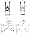
実施例1及び比較例1〜3について、図1の(A)〜(G)を参照して説明する。なお、図1の(A)は、実施例1の浸漬ノズルを、図1の(B),(C),(D)は、比較例1,2,3の浸漬ノズルを、それぞれ示した図であって、それらは、いずれも溶鋼流通方向に平行な方向に縦割りにした図である。また、図1の(E)は同(A)の浸漬ノズル(実施例1)の、図1の(F)は同(C)の浸漬ノズル(比較例2)の、図1の(G)は同(D)の浸漬ノズル(比較例3)の、溶鋼流通方向に対して平行な方向の突起部の断面をそれぞれ示した図であって、実施例1,比較例2,比較例3の浸漬ノズルの「水モデル実験」の結果を説明するための図である。
<Example 1, Comparative Examples 1-3 (refer FIG. 1)>
Example 1 and Comparative Examples 1 to 3 will be described with reference to FIGS. 1A shows the immersion nozzle of Example 1, and FIGS. 1B, 1C, and 1D show the immersion nozzles of Comparative Examples 1, 2, and 3, respectively. However, they are all divided in a direction parallel to the molten steel flow direction. 1 (E) is the immersion nozzle (Example 1) of the same (A), FIG. 1 (F) is the immersion nozzle (Comparative Example 2) of the same (C), and FIG. These are the figures which each showed the cross section of the protrusion part of the direction parallel to the molten steel distribution | circulation direction of the immersion nozzle (Comparative Example 3) of the same (D), Comprising: Example 1, Comparative Example 2, and Comparative Example 3 It is a figure for demonstrating the result of the "water model experiment" of an immersion nozzle.
実施例1について、図1の(A),(E)を参照して説明すると、本実施例1は、内径φ80mmの透明なアクリル製浸漬ノズル(10a)に高さH=13mm,突起部上端の角度α=45°,突起部下端の角度β=80°の突起部(11a)を配設した例である。また、比較例1は、図1の(B)に示すように、突起部を配設しない浸漬ノズル(ストレートノズル)(10b)であり、比較例2は、図1の(C),(F)に示すように、高さH=13mm,突起部上端の角度α=85°,突起部下端の角度β=50°の突起部(11c)を配設した浸漬ノズル(10c)であり、比較例3は、図1の(D),(G)に示すように、高さH=13mm,突起部上端の角度α=80°,突起部下端の角度β=85°の突起部(11d)を配設した浸漬ノズル(10d)である。
なお、実施例1の突起部(11a)、比較例2の突起部(11c)および比較例3の突起部(11d)は、いずれも環状に連続しておらず、溶鋼流通方向に対して垂直な一面上に4ヶ、溶鋼流通方向に対して平行な方向に3段の合計12ヶ配設した。
Example 1 will be described with reference to FIGS. 1A and 1E. In Example 1, a transparent acrylic immersion nozzle (10a) having an inner diameter of φ80 mm has a height H = 13 mm and the upper end of the protrusion. In this example, a protrusion (11a) having an angle α = 45 ° and an angle β = 80 ° at the lower end of the protrusion is provided. Further, as shown in FIG. 1B, the comparative example 1 is an immersion nozzle (straight nozzle) (10b) in which no protrusions are provided, and the comparative example 2 is shown in FIGS. ) Is a submerged nozzle (10c) provided with a protrusion (11c) having a height H = 13 mm, an angle α = 85 ° at the upper end of the protrusion, and an angle β = 50 ° at the lower end of the protrusion. In Example 3, as shown in FIGS. 1D and 1G, a protrusion (11d) having a height H = 13 mm, an angle α = 80 ° at the upper end of the protrusion, and an angle β = 85 ° at the lower end of the protrusion. Is an immersion nozzle (10d).
In addition, the protrusion part (11a) of Example 1, the protrusion part (11c) of Comparative Example 2, and the protrusion part (11d) of Comparative Example 3 are not continuous in an annular shape, and are perpendicular to the molten steel flow direction. A total of 12 pieces were arranged in four rows on a flat surface and three steps in a direction parallel to the flowing direction of the molten steel.
実施例1及び比較例1〜3の各浸漬ノズルに対して「水モデル実験」を行った。まず、スループット:5steel T/min相当で内孔部の水の流れを目視で確認した結果、実施例1の浸漬ノズル(10a)は、突起部(11a)直下で乱流が発生している部分(13a)が認められる[図1(E)の“水の流れ(12a)”参照]。一方、比較例3の浸漬ノズル(10d)は、突起部(11d)直下で乱流が発生している部分(13d)は認められるものの、実施例1とは異なり、突起部(11d)直上で流れが遅い領域(14d)が認められ、実機では、ここにアルミナが付着するものと考えられる[図1(G)の“水の流れ(12d)”参照]。
これに対して、比較例2の浸漬ノズル(10c)は、突起部(11c)直下に乱流は見られず、整流効果は期待できない。更に、突起部(11c)の直上では、流れが遅い領域(14c)が確認され、比較例3と同様、実機では、ここにアルミナが付着するものと考えられる[図1(F)の“水の流れ(12c)”参照]。
A “water model experiment” was performed on each immersion nozzle of Example 1 and Comparative Examples 1 to 3. First, as a result of visually confirming the flow of water in the inner hole at a throughput of 5 steel T / min, the immersion nozzle (10a) of Example 1 is a portion where turbulent flow is generated immediately below the protrusion (11a). (13a) is observed [see “Water Flow (12a)” in FIG. 1 (E)]. On the other hand, the immersion nozzle (10d) of Comparative Example 3 has a portion (13d) where turbulent flow is generated immediately below the protrusion (11d), but unlike Example 1, it is directly above the protrusion (11d). A slow flow region (14d) is observed, and it is considered that alumina adheres to the actual machine (see "Water flow (12d)" in FIG. 1 (G)).
On the other hand, in the immersion nozzle (10c) of Comparative Example 2, no turbulent flow is seen immediately below the protrusion (11c), and a rectifying effect cannot be expected. Further, a region (14c) in which the flow is slow is confirmed immediately above the protrusion (11c), and it is considered that alumina adheres to the actual machine as in Comparative Example 3 ["Water" in FIG. Flow (see 12c) ”].
続いて、実施例1及び比較例1〜3の各浸漬ノズルにおける最大スループットを測定した。これは、浸漬ノズル上部に取り付けているスライドバルブを全開にし、水を循環させるポンプ近傍にある流量調整バルブを調整することで、モールド内の水面を所定の高さ(吐出孔上端から上に250mmの位置)に安定させ、この時の流量をフロート式流量計にて測定したものである。 Subsequently, the maximum throughput in each immersion nozzle of Example 1 and Comparative Examples 1 to 3 was measured. This is because the slide valve attached to the upper part of the immersion nozzle is fully opened, and the water level in the mold is adjusted to a predetermined height (250 mm above the upper end of the discharge hole) by adjusting the flow rate adjustment valve near the pump that circulates water. The flow rate at this time was measured with a float type flow meter.
測定結果は、比較例1の浸漬ノズル(ストレートノズル)(10b)では、最大スループット:1200L/minまで流れ、比較例2の浸漬ノズル(10c)では、1130L/min流れたのに対し、比較例3の浸漬ノズル(10d)では、1070L/minしか流れなかった。
一方、実施例1の浸漬ノズル(10a)では、1180L/minと、突起部(11a)を配設した影響が認められるが、実機操業上影響が無い程度にとどめることができた。これは、実施例1では、突起部上端の角度“α”が45°であって、突起部自体の抵抗が少なく、突起の直上に流れが少ない領域が発生せず、突起部直下で乱流が発生しても、スループットが確保できたのに対し、比較例2では、突起部上端の角度“α”が85°と抵抗が大きく、更に、比較例3は、突起部上端の角度“α”が大きいことに加え、突起部下端の角度“β”も85°と大きいため、水がスムーズに流れない状態になってしまったと考えられる。この比較例2,3のように、突起部直上で流体がスムーズに流れないと、流れが少ない領域(14c),(14d)ができ、実機では、ここがアルミナ付着の起点になっていることが経験的に判明している。
The measurement results show that the maximum throughput of the immersion nozzle (straight nozzle) (10b) of Comparative Example 1 was up to 1200 L / min, and that of the immersion nozzle (10c) of Comparative Example 2 was 1130 L / min. With the immersion nozzle 3 (10d), only 1070 L / min flowed.
On the other hand, in the immersion nozzle (10a) of Example 1, 1180 L / min and the effect of disposing the protrusion (11a) were recognized, but the effect was not affected on the actual machine operation. In the first embodiment, the angle “α” at the upper end of the protrusion is 45 °, the resistance of the protrusion itself is small, and there is no region of low flow immediately above the protrusion. Throughput could be ensured even if this occurred, but in Comparative Example 2, the angle “α” at the upper end of the protrusion was as high as 85 °, and in Comparative Example 3, the angle “α” at the upper end of the protrusion was high. In addition to the large “”, the angle “β” at the lower end of the protrusion is also as large as 85 °, so it is considered that water has not flowed smoothly. As in Comparative Examples 2 and 3, if the fluid does not flow smoothly just above the protrusion, areas (14c) and (14d) where there is little flow can be created, and this is the starting point for alumina adhesion in the actual machine. Has been found empirically.
更に、実施例1と比較例2の実機形状ノズルを試作して、実機テストを行った。テスト条件は、鋼種:低炭素鋼,モールドサイズ:230×1500mm,スループット4T/minで、上ノズルからアルゴンガスを7L/minで吹き込んだ。
結果は、比較例2では、モールド(24)左右の狭面の冷却水温度差が5.8℃であったのに対し、実施例1では、0.5℃であり、モールド(24)内の偏流防止効果が認められた。また、スライドプレート(23)の開度も、比較例2では、82%であったのに対し、実施例1のノズルでは77%であって、突起が抵抗になっていないことを示した。さらに、使用後のノズルを回収して切断してみたところ、比較例2では、突起間にアルミナが最大12mmも付着して内管を狭窄していたのに対し、実施例1では、アルミナ付着量が最大でも1.5mmとほとんど無く良好であった。
Furthermore, the actual machine-shaped nozzles of Example 1 and Comparative Example 2 were prototyped and the actual machine test was performed. The test conditions were steel type: low carbon steel, mold size: 230 × 1500 mm, throughput 4 T / min, and argon gas was blown from the upper nozzle at 7 L / min.
As a result, in Comparative Example 2, the cooling water temperature difference between the left and right narrow surfaces of the mold (24) was 5.8 ° C., whereas in Example 1, it was 0.5 ° C. The drift prevention effect was recognized. Further, the opening degree of the slide plate (23) was 82% in Comparative Example 2, whereas it was 77% in the nozzle of Example 1, indicating that the protrusion was not in resistance. Furthermore, when the nozzles after use were collected and cut, the comparative example 2 had a maximum of 12 mm of alumina adhering between the protrusions and narrowed the inner tube, whereas in Example 1, the alumina adhered The maximum amount was 1.5 mm at most and was good.
<実施例2,比較例4(図2参照)>
実施例2および比較例4を、図2の(A)〜(D)を参照して説明する。なお、図2の(A)は、実施例2の浸漬ノズルを、図2の(B)は、比較例4の浸漬ノズルを、それぞれ示した図であって、それらは、いずれも溶鋼流通方向に平行な方向に縦割りにした図である。また、図2の(C)は、同(A)の浸漬ノズル(実施例2)の、図2の(D)は、同(B)の浸漬ノズル(比較例4)の、吐出流を説明するための概略図である。
<Example 2, Comparative Example 4 (see FIG. 2)>
Example 2 and Comparative Example 4 will be described with reference to (A) to (D) of FIG. 2A shows the immersion nozzle of Example 2, and FIG. 2B shows the immersion nozzle of Comparative Example 4, both of which are in the molten steel flow direction. FIG. 2C illustrates the discharge flow of the immersion nozzle (Example 2) of FIG. 2A, and FIG. 2D illustrates the discharge flow of the immersion nozzle of FIG. 2B (Comparative Example 4). It is the schematic for doing.
実施例2は、図2の(A)に示すように、内径φ70mmの透明なアクリル製浸漬ノズル(20a)に、高さ12mm,突起部上端の角度:30°,突起部下端の角度:65°の突起部(21a)を、溶鋼流通方向に対して垂直な一面上に4ヶずつ3段、合計12ヶ配設した例である。一方、比較例4は、図2の(B)に示すように、実施例2と同じ縦断面形状を有する突起部ではあるが、溶鋼流通方向に対して垂直な一面上では連続した環状の突起部(21b)であり、これを3段配設した浸漬ノズル(20b)である。 In Example 2, as shown in FIG. 2A, a transparent acrylic immersion nozzle (20a) having an inner diameter φ of 70 mm is provided with a height of 12 mm, an angle at the upper end of the protruding portion: 30 °, and an angle at the lower end of the protruding portion: 65. This is an example in which four protrusions (21a) are arranged in three steps of four on a surface perpendicular to the molten steel flow direction, for a total of twelve. On the other hand, as shown in FIG. 2 (B), Comparative Example 4 is a protrusion having the same vertical cross-sectional shape as Example 2, but a continuous annular protrusion on one surface perpendicular to the molten steel flow direction. Part (21b), which is an immersion nozzle (20b) provided with three stages.
実施例2および比較例4の各浸漬ノズルに対して「水モデル実験」を行った。水モデル実験の条件としては、図2の(C),(D)に示すように、スライドプレート(23)は3枚式で、中プレートをモールド(24)の長辺と平行に摺動させて流量を制御し、スループット4steelT/min相当で行った。また、モールド(24)内の水(26)の流れが観察しやすいように、スライドプレート(23)の直上に設置した上ノズル(22)から、空気を5L/minで吹き込んだ。 A “water model experiment” was performed on each immersion nozzle of Example 2 and Comparative Example 4. As conditions for the water model experiment, as shown in (C) and (D) of FIG. 2, the slide plate (23) is a three-plate type, and the middle plate is slid parallel to the long side of the mold (24). The flow rate was controlled, and the throughput was equivalent to 4 steelT / min. Further, air was blown at 5 L / min from the upper nozzle (22) installed immediately above the slide plate (23) so that the flow of water (26) in the mold (24) can be easily observed.
実施例2の結果を図2の(C)に、比較例4の結果を図2の(D)に示す。これは、吐出孔から吐出されたモールド(24)内での水の流れ、すなわち、吐出流(25a),(25b)を簡易的に図示したものである。
突起部が独立突起である実施例2の浸漬ノズル(20a)では、モールド(24)内の水の流れ[吐出流(25a)]がほぼ左右均等で安定していたのに対し、突起部が環状突起である比較例4の浸漬ノズル(20b)では、右側の吐出流(25b)が左側より深く潜りこんでおり、偏流を解決できていないことが判ることから、溶鋼流通方向に対して垂直な一面上において連続した環状突起より、独立した突起の方が整流効果に関して好ましいことがわかる。
The result of Example 2 is shown in FIG. 2C, and the result of Comparative Example 4 is shown in FIG. This is a simplified illustration of the flow of water in the mold (24) discharged from the discharge holes, that is, the discharge flows (25a) and (25b).
In the immersion nozzle (20a) of Example 2 in which the protrusions are independent protrusions, the water flow [discharge flow (25a)] in the mold (24) was almost even and stable, whereas the protrusions were In the immersion nozzle (20b) of Comparative Example 4, which is an annular protrusion, the right discharge flow (25b) is deeper than the left, and it is understood that the uneven flow cannot be solved. It can be seen that independent protrusions are preferable with respect to the rectifying effect rather than continuous annular protrusions on one surface.
<実施例3〜7,比較例5〜9(図3参照)>
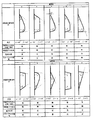
図3に、実施例3〜7,比較例5〜9の浸漬ノズルに配設した「突起部の断面形状(溶鋼流通方向に対して平行に切断した断面形状)」を示した。このうち、実施例5の突起部は、その上端部高さ(ノズル内管中心方向への高さ“h”)を1.5mmとした例である。なお、実施例3〜7,比較例5〜9の浸漬ノズルは、いずれも内径φ80mmの透明なアクリル製浸漬ノズルであり、また、最大高さ9mmの突起部を配設した例である。
<Examples 3 to 7, Comparative Examples 5 to 9 (see FIG. 3)>
FIG. 3 shows “a cross-sectional shape of the protrusion (a cross-sectional shape cut parallel to the molten steel flow direction)” disposed in the immersion nozzles of Examples 3 to 7 and Comparative Examples 5 to 9. Among these, the protrusion of Example 5 is an example in which the height of the upper end (height “h” toward the center of the nozzle inner tube) is 1.5 mm. The immersion nozzles of Examples 3 to 7 and Comparative Examples 5 to 9 are all transparent acrylic immersion nozzles having an inner diameter of φ80 mm, and are examples in which protrusions with a maximum height of 9 mm are disposed.
実施例3〜7,比較例5〜9の浸漬ノズルに対して、「水モデル実験」を行った。その結果を図3に表示した。図3から明らかなように、本発明で特定する「突起部上端の角度α=60°以下で、かつ、突起部下端の角度“β”が突起部上端の角度“α”よりも大きく、90°以下」の範囲内の実施例3,4,6,7の浸漬ノズルでは、いずれも、突起部直上に流れの遅い領域は認められず、突起部直下には乱流が発生しているのが認められ、かつ、良好な整流効果が得られていた。また、実施例5のように、突起部上端部の高さ(ノズル内管中心方向への高さ“h”)を“1.5mm”としても、この高さが2mm未満であって、かつ「突起部上端の角度“α”」が本発明で特定する範囲内とすることで、突起部直上に流れの遅い領域は認められず、かつ良好な整流効果が得られることが判った。
これに対して、本発明で特定する「突起部上端の角度“α”と下端の角度“β”」の少なくとも片方が範囲外の比較例5〜9の浸漬ノズルは、突起部直上に流れの遅い領域が認められるものや、突起部直下に乱流が発生していないものであり、良好な整流効果が得られなかったものや、良好な整流効果は得られたものの、スループットが確保できないものであった。
A “water model experiment” was performed on the immersion nozzles of Examples 3 to 7 and Comparative Examples 5 to 9. The results are shown in FIG. As apparent from FIG. 3, “the angle α of the upper end of the protrusion is not more than 60 ° and the angle“ β ”of the lower end of the protrusion is larger than the angle“ α ”of the upper end of the protrusion. In all of the immersion nozzles of Examples 3, 4, 6, and 7 within the range of “° or less”, no slow flow area was observed immediately above the protrusion, and turbulence was generated immediately below the protrusion. And a good rectifying effect was obtained. Further, as in Example 5, even when the height of the upper end of the protrusion (height “h” in the direction of the nozzle inner tube center) is set to “1.5 mm”, this height is less than 2 mm, and It was found that when the “angle“ α ”at the upper end of the protrusion” is within the range specified by the present invention, a slow flow region is not observed immediately above the protrusion and a good rectifying effect is obtained.
On the other hand, the immersion nozzles of Comparative Examples 5 to 9 in which at least one of the “upper end angle“ α ”and the lower end angle“ β ”” specified in the present invention is out of the range flow directly above the protrusion. A slow region is observed, or turbulent flow is not generated directly below the protrusion, and a good rectification effect is not obtained, or a good rectification effect is obtained, but a throughput cannot be secured Met.
以上詳記したとおり、本発明に係る鋳造用ノズルは、鋳造用ノズルの溶鋼流通孔部に突起部を配設する場合、該突起部間にアルミナが付着・堆積して突起部の整流効果を減ずることを防止するため、高さ:3〜20mmを配設する浸漬ノズルにおいて、溶鋼流通方向に対して平行な方向、すなわち、縦断面における“ノズル内管と突起部の上端部の成す角度”が60°以下で、かつ、“ノズル内管と突起部の下端部の成す角度”が“ノズル内管と突起部の上端部の成す角度”よりも大きく、90°以下であることを特徴とする。これにより、突起部の配設による整流効果を維持しながら、突起部の抵抗を軽減することで所定のスループットを確保できるので、操業の安定化や鋼の鋳片品質の向上に寄与するものである。 As described in detail above, when the casting nozzle according to the present invention is provided with projections in the molten steel flow holes of the casting nozzle, alumina adheres and accumulates between the projections, and the rectifying effect of the projections is achieved. In order to prevent reduction, in the immersion nozzle having a height of 3 to 20 mm, the direction parallel to the molten steel flow direction, that is, the “angle formed by the nozzle inner tube and the upper end of the protrusion” in the longitudinal section. Is 60 ° or less, and “the angle formed by the nozzle inner tube and the lower end of the projection” is larger than “the angle formed by the nozzle inner tube and the upper end of the projection” and is 90 ° or less. To do. As a result, the predetermined throughput can be secured by reducing the resistance of the protrusion while maintaining the rectifying effect due to the arrangement of the protrusion, which contributes to the stabilization of the operation and the improvement of the quality of the steel slab. is there.
(10a),(10b),(10c),(10d),(20a),(20b) ・・・・・・ 浸漬ノズル
(11a), − (11c),(11d),(21a),(21b) ・・・・・・ 突起部
(12a), − (12c),(12d) ・・・・・・ 水の流れ
(22) ・・・・・・ 上ノズル
(23) ・・・・・・ スライドプレート
(24) ・・・・・・ モールド
(25a),(25b) ・・・・・・ 吐出流
(26) ・・・・・・ 水
α ・・・・・・ 突起部上端の角度
β ・・・・・・ 突起部下端の角度
H ・・・・・・ 突起部の高さ
h ・・・・・・ 突起部上端の高さ(ノズル内管中心方向への高さ)
(10a), (10b), (10c), (10d), (20a), (20b) ・ ・ ・ ・ ・ ・ Immersion nozzle
(11a),-(11c), (11d), (21a), (21b) ··· Projection
(12a), − (12c), (12d) ・ ・ ・ ・ ・ ・ Flow of water
(22) ・ ・ ・ ・ ・ ・ Upper nozzle
(23) ・ ・ ・ ・ ・ ・ Slide plate
(24) ・ ・ ・ ・ ・ ・ Mold
(25a), (25b) ・ ・ ・ ・ ・ ・ Discharge flow
(26) ・ ・ ・ ・ ・ ・ Water α ・ ・ ・ ・ ・ ・ Angle at the top of the projection β ・ ・ ・ ・ ・ ・ Angle at the bottom of the projection H ・ ・ ・ ・ ・ ・ Height of the projection h ... Height at the top of the protrusion (height toward the nozzle inner tube center)
Claims (4)
Priority Applications (1)
| Application Number | Priority Date | Filing Date | Title |
|---|---|---|---|
| JP2004118143A JP4564774B2 (en) | 2004-04-13 | 2004-04-13 | Nozzle for continuous casting of steel |
Applications Claiming Priority (1)
| Application Number | Priority Date | Filing Date | Title |
|---|---|---|---|
| JP2004118143A JP4564774B2 (en) | 2004-04-13 | 2004-04-13 | Nozzle for continuous casting of steel |
Publications (2)
| Publication Number | Publication Date |
|---|---|
| JP2005297022A true JP2005297022A (en) | 2005-10-27 |
| JP4564774B2 JP4564774B2 (en) | 2010-10-20 |
Family
ID=35329199
Family Applications (1)
| Application Number | Title | Priority Date | Filing Date |
|---|---|---|---|
| JP2004118143A Expired - Lifetime JP4564774B2 (en) | 2004-04-13 | 2004-04-13 | Nozzle for continuous casting of steel |
Country Status (1)
| Country | Link |
|---|---|
| JP (1) | JP4564774B2 (en) |
Cited By (2)
| Publication number | Priority date | Publication date | Assignee | Title |
|---|---|---|---|---|
| JP2010188402A (en) * | 2009-02-20 | 2010-09-02 | Kobe Steel Ltd | Immersion nozzle for curved type continuous casting machine |
| KR20180081729A (en) * | 2015-11-10 | 2018-07-17 | 베수비우스 유에스에이 코포레이션 | A casting nozzle comprising a flow deflector |
Citations (7)
| Publication number | Priority date | Publication date | Assignee | Title |
|---|---|---|---|---|
| JPS57146942U (en) * | 1981-02-24 | 1982-09-16 | ||
| JPS62207568A (en) * | 1986-03-05 | 1987-09-11 | デイデイエル−ヴエルケ・アクチエンゲゼルシヤフト | Dip pipe |
| JPS632545A (en) * | 1986-06-23 | 1988-01-07 | Nippon Kokan Kk <Nkk> | Molten metal pouring nozzle |
| JPS645761U (en) * | 1987-06-30 | 1989-01-13 | ||
| JPH04220148A (en) * | 1990-12-19 | 1992-08-11 | Nippon Steel Corp | Molten steel supplying nozzle |
| JPH06269913A (en) * | 1993-03-18 | 1994-09-27 | Toshiba Ceramics Co Ltd | Immersion nozzle for continuous casting |
| JPH1147896A (en) * | 1997-07-29 | 1999-02-23 | Kobe Steel Ltd | Immersion nozzle for continuous casting |
-
2004
- 2004-04-13 JP JP2004118143A patent/JP4564774B2/en not_active Expired - Lifetime
Patent Citations (7)
| Publication number | Priority date | Publication date | Assignee | Title |
|---|---|---|---|---|
| JPS57146942U (en) * | 1981-02-24 | 1982-09-16 | ||
| JPS62207568A (en) * | 1986-03-05 | 1987-09-11 | デイデイエル−ヴエルケ・アクチエンゲゼルシヤフト | Dip pipe |
| JPS632545A (en) * | 1986-06-23 | 1988-01-07 | Nippon Kokan Kk <Nkk> | Molten metal pouring nozzle |
| JPS645761U (en) * | 1987-06-30 | 1989-01-13 | ||
| JPH04220148A (en) * | 1990-12-19 | 1992-08-11 | Nippon Steel Corp | Molten steel supplying nozzle |
| JPH06269913A (en) * | 1993-03-18 | 1994-09-27 | Toshiba Ceramics Co Ltd | Immersion nozzle for continuous casting |
| JPH1147896A (en) * | 1997-07-29 | 1999-02-23 | Kobe Steel Ltd | Immersion nozzle for continuous casting |
Cited By (3)
| Publication number | Priority date | Publication date | Assignee | Title |
|---|---|---|---|---|
| JP2010188402A (en) * | 2009-02-20 | 2010-09-02 | Kobe Steel Ltd | Immersion nozzle for curved type continuous casting machine |
| KR20180081729A (en) * | 2015-11-10 | 2018-07-17 | 베수비우스 유에스에이 코포레이션 | A casting nozzle comprising a flow deflector |
| KR102593854B1 (en) * | 2015-11-10 | 2023-10-25 | 베수비우스 유에스에이 코포레이션 | Cast nozzle with flow deflector |
Also Published As
| Publication number | Publication date |
|---|---|
| JP4564774B2 (en) | 2010-10-20 |
Similar Documents
| Publication | Publication Date | Title |
|---|---|---|
| JPWO2005070589A1 (en) | Immersion nozzle for continuous casting and continuous casting method using the same | |
| US7905432B2 (en) | Casting nozzle | |
| JP4564774B2 (en) | Nozzle for continuous casting of steel | |
| JP2007152431A (en) | Casting mold for continuous casting of metal | |
| JP6577841B2 (en) | Immersion nozzle | |
| JP2005125389A (en) | Immersion nozzle for continuous casting | |
| JP2006150434A (en) | Continuous casting method | |
| JP2011110603A (en) | Immersion nozzle for continuous casting and continuous casting method | |
| JP2005230826A (en) | Nozzle for supplying molten metal | |
| JP2004283857A (en) | Nozzle for continuously casting steel | |
| JP4076516B2 (en) | Immersion nozzle for continuous casting of steel | |
| JPH1147897A (en) | Immersion nozzle for continuously casting thin and wide cast slab | |
| JP4266312B2 (en) | Nozzle for continuous casting of steel | |
| JP2006520694A (en) | Immersion injection nozzle with dynamic stabilization function | |
| JP5027625B2 (en) | Immersion nozzle for continuous casting | |
| JPS59225862A (en) | Immersion nozzle for continuous casting device | |
| KR200285346Y1 (en) | collecter nozzle or submerged entry nozzle for continuous casting | |
| CN113226594B (en) | Immersion nozzle | |
| JP4434826B2 (en) | Immersion nozzle for continuous casting of steel | |
| RU2490092C2 (en) | Submersible teeming barrel | |
| JP6695731B2 (en) | Lower nozzle | |
| JP4321813B2 (en) | Immersion nozzle for continuous casting of steel | |
| KR100470661B1 (en) | A Device For Supplying Molten Steel Uniformly And A Continuous Caster | |
| JP2000158126A (en) | Molten metal discharging slide gate plate | |
| KR20040055973A (en) | Apparatus for improving the clogging near the nozzle exit in the continuous casting |
Legal Events
| Date | Code | Title | Description |
|---|---|---|---|
| A621 | Written request for application examination |
Free format text: JAPANESE INTERMEDIATE CODE: A621 Effective date: 20070409 |
|
| RD02 | Notification of acceptance of power of attorney |
Free format text: JAPANESE INTERMEDIATE CODE: A7422 Effective date: 20070409 |
|
| A977 | Report on retrieval |
Free format text: JAPANESE INTERMEDIATE CODE: A971007 Effective date: 20071015 |
|
| A131 | Notification of reasons for refusal |
Free format text: JAPANESE INTERMEDIATE CODE: A131 Effective date: 20090526 |
|
| A521 | Request for written amendment filed |
Free format text: JAPANESE INTERMEDIATE CODE: A523 Effective date: 20090716 |
|
| TRDD | Decision of grant or rejection written | ||
| A01 | Written decision to grant a patent or to grant a registration (utility model) |
Free format text: JAPANESE INTERMEDIATE CODE: A01 Effective date: 20100706 |
|
| A01 | Written decision to grant a patent or to grant a registration (utility model) |
Free format text: JAPANESE INTERMEDIATE CODE: A01 |
|
| A61 | First payment of annual fees (during grant procedure) |
Free format text: JAPANESE INTERMEDIATE CODE: A61 Effective date: 20100802 |
|
| FPAY | Renewal fee payment (event date is renewal date of database) |
Free format text: PAYMENT UNTIL: 20130806 Year of fee payment: 3 |
|
| R150 | Certificate of patent or registration of utility model |
Ref document number: 4564774 Country of ref document: JP Free format text: JAPANESE INTERMEDIATE CODE: R150 Free format text: JAPANESE INTERMEDIATE CODE: R150 |
|
| S531 | Written request for registration of change of domicile |
Free format text: JAPANESE INTERMEDIATE CODE: R313531 |
|
| R350 | Written notification of registration of transfer |
Free format text: JAPANESE INTERMEDIATE CODE: R350 |
|
| R250 | Receipt of annual fees |
Free format text: JAPANESE INTERMEDIATE CODE: R250 |
|
| R250 | Receipt of annual fees |
Free format text: JAPANESE INTERMEDIATE CODE: R250 |
|
| R250 | Receipt of annual fees |
Free format text: JAPANESE INTERMEDIATE CODE: R250 |
|
| R250 | Receipt of annual fees |
Free format text: JAPANESE INTERMEDIATE CODE: R250 |
|
| R250 | Receipt of annual fees |
Free format text: JAPANESE INTERMEDIATE CODE: R250 |
|
| R250 | Receipt of annual fees |
Free format text: JAPANESE INTERMEDIATE CODE: R250 |
|
| R250 | Receipt of annual fees |
Free format text: JAPANESE INTERMEDIATE CODE: R250 |
|
| R250 | Receipt of annual fees |
Free format text: JAPANESE INTERMEDIATE CODE: R250 |