JP2005296691A - Game machine - Google Patents

Game machine Download PDF

Info

Publication number
JP2005296691A
JP2005296691A JP2005204770A JP2005204770A JP2005296691A JP 2005296691 A JP2005296691 A JP 2005296691A JP 2005204770 A JP2005204770 A JP 2005204770A JP 2005204770 A JP2005204770 A JP 2005204770A JP 2005296691 A JP2005296691 A JP 2005296691A
Authority
JP
Japan
Prior art keywords
display
game
predetermined
display area
area
Prior art date
Legal status (The legal status is an assumption and is not a legal conclusion. Google has not performed a legal analysis and makes no representation as to the accuracy of the status listed.)
Pending
Application number
JP2005204770A
Other languages
Japanese (ja)
Inventor
Kazuo Okada
和生 岡田
Current Assignee (The listed assignees may be inaccurate. Google has not performed a legal analysis and makes no representation or warranty as to the accuracy of the list.)
Universal Entertainment Corp
Original Assignee
Aruze Corp
Priority date (The priority date is an assumption and is not a legal conclusion. Google has not performed a legal analysis and makes no representation as to the accuracy of the date listed.)
Filing date
Publication date
Application filed by Aruze Corp filed Critical Aruze Corp
Priority to JP2005204770A priority Critical patent/JP2005296691A/en
Publication of JP2005296691A publication Critical patent/JP2005296691A/en
Pending legal-status Critical Current

Links

Images

Abstract

<P>PROBLEM TO BE SOLVED: To provide a game machine, when it is necessary to change the position of a predetermined switch, easily responding thereto on a game board. <P>SOLUTION: This game machine is provided with a liquid crystal display 4 displaying a prescribed picture, a touch panel 3 disposed in a front side of a transparent member of a front frame 2 and worked as a switch as a predetermined operation by a player, and a sub CPU 41 detecting the position where the player performs the predetermined operation through the touch panel 3 and determined whether the detected position is the position corresponding to the prescribed area of performing the predetermined information in the liquid crystal display 4. <P>COPYRIGHT: (C)2006,JPO&NCIPI

Description

本発明は、パチンコ遊技機などの遊技機に関する。   The present invention relates to a gaming machine such as a pachinko gaming machine.

従来のパチンコ遊技機では、所定のスイッチとして、透明なタッチパネルを用いたものがある。例えば、ある従来のパチンコ遊技機では、遊技盤上に、各種の遊技部材が設けられており、遊技盤の前面には、遊技盤の遊技領域を遊技者が視認できるように、透明なガラスが配置されている。そして、この透明なガラスの外側の表面の所定の位置には、透明なタッチパネルが、店員呼び出しのためのスイッチとして、配置されている。   Some conventional pachinko machines use a transparent touch panel as a predetermined switch. For example, in a conventional pachinko machine, various game members are provided on the game board, and transparent glass is provided on the front of the game board so that the player can visually recognize the game area of the game board. Has been placed. A transparent touch panel is arranged as a switch for calling a clerk at a predetermined position on the outer surface of the transparent glass.

上記タッチパネルは、パチンコ遊技機が設置されている島に配置されている呼び出し装置に接続されている。そして、パチンコ遊技機において、タッチパネルの周辺には、店員呼び出し用のスイッチであることを示す表示シートが配置されている。   The touch panel is connected to a calling device arranged on an island where a pachinko gaming machine is installed. In the pachinko gaming machine, a display sheet indicating that it is a switch for calling a clerk is arranged around the touch panel.

遊技者は、店員を呼び出したいときには、上記表示シートに基づいて、タッチパネルを押す操作を行うと、押し操作を示す信号が呼び出し装置に送られる。呼び出し装置は、上記信号に基づいて、例えば、店員呼び出し中であることを示す所定のランプを点灯させる(例えば、特許文献1参照)。
特許2551819号
When the player wants to call the store clerk, if the player performs an operation of pressing the touch panel based on the display sheet, a signal indicating the pressing operation is sent to the calling device. Based on the signal, for example, the calling device turns on a predetermined lamp indicating that the store clerk is being called (see, for example, Patent Document 1).
Patent 2551819

しかしながら、上述した従来技術では、以下のような問題があった。遊技盤上には、各種の遊技部材が存在することから、上述した透明なタッチパネルが配置される位置は、遊技領域外の位置に限定されていた。このため、パチンコ遊技機の機種変更により、上記所定のスイッチの位置変更が必要な場合や、遊技中において、上記所定のスイッチの位置変更が必要な場合には、その都度、透明なタッチパネルや表示シートを取り外し、別の位置に設置し直すという作業が必要となっていた。   However, the above-described conventional technology has the following problems. Since various game members exist on the game board, the position where the above-described transparent touch panel is disposed is limited to a position outside the game area. For this reason, if the position of the predetermined switch needs to be changed due to a change in the model of the pachinko gaming machine, or if it is necessary to change the position of the predetermined switch during the game, a transparent touch panel or display It was necessary to remove the seat and re-install it in a different position.

本発明は、以上のような問題点に鑑みてなされたものであり、遊技盤上において、所定のスイッチの位置変更の必要が生じた場合に、容易に対処できる遊技機を提供することを目的とする。   The present invention has been made in view of the above-described problems, and an object of the present invention is to provide a gaming machine that can easily cope with a need to change the position of a predetermined switch on a gaming board. And

以上の問題点を解決するために、本発明は、特定の情報(例えば、特別図柄、演出画像、遊技データに関する画像、店員呼び出しのための画像、遊技説明情報に関する画像などの特定の画像)を表示する表示手段(例えば、液晶表示装置4)と、前記表示手段における表示動作を制御する表示制御手段(例えば、サブCPU41)と、前記表示手段の前面側に配設され、遊技部材が配設された遊技盤ベース(例えば、遊技盤ベース19)からなる遊技盤と、前記遊技盤の前面側に配設された前面枠とを有する遊技機であって、前記遊技盤ベースの少なくとも一部と、前記前面枠(例えば、前枠2)の少なくとも一部とは、前記表示手段に表示される前記特定の情報を正面側から見て視認可能な透過性部材で形成され、前記前面枠の透過性部材の前面側に配置され、遊技者による所定の操作によりスイッチとして働くタッチパネル(例えば、タッチパネル3)と、前記タッチパネルにおいて遊技者により所定の操作が行われた位置を検出する第一位置検出手段(例えば、サブCPU41)と、前記第一位置検出手段により検出された位置が、前記表示手段において前記特定の情報の表示が行われる特定領域に対応した位置(例えば、タッチパネル3における位置)であるかを判断する手段(例えば、サブCPU41)を有することを特徴とするものである。   In order to solve the above problems, the present invention provides specific information (for example, specific images such as special symbols, effects images, images related to game data, images for calling store clerks, images related to game description information). Display means (for example, liquid crystal display device 4) for displaying, display control means (for example, sub CPU 41) for controlling the display operation in the display means, and a game member are provided on the front side of the display means A gaming machine comprising a gaming board base (for example, gaming board base 19) and a front frame disposed on the front side of the gaming board, wherein the gaming board base includes at least a part of the gaming board base; The at least part of the front frame (for example, the front frame 2) is formed of a transparent member that is visible when the specific information displayed on the display means is viewed from the front side, and is transmitted through the front frame. Sexual member A touch panel (e.g., touch panel 3) disposed on the front surface and serving as a switch by a predetermined operation by the player, and first position detection means (e.g., a position where the predetermined operation is performed by the player on the touch panel) It is determined whether the position detected by the sub CPU 41) and the first position detecting means is a position corresponding to a specific area where the specific information is displayed on the display means (for example, a position on the touch panel 3). It has a means (for example, sub CPU41) to do.

このような本発明によれば、タッチパネルは、前面枠の前面側を覆うように配置することができ、タッチパネル全体がスイッチとしての機能を持つので、遊技盤の遊技領域の広範囲において、スイッチの設置が可能になる。この結果、上記スイッチの位置変更の必要が生じた場合(機種変更など)でも、ハードウェア構成を変更することなく、スイッチの位置の変更が可能となり、スイッチの位置変更に対して容易に対処することが可能となる。   According to the present invention, the touch panel can be arranged so as to cover the front side of the front frame, and the entire touch panel has a function as a switch. Therefore, the switch is installed in a wide range of the game area of the game board. Is possible. As a result, even if the switch position needs to be changed (model change, etc.), the switch position can be changed without changing the hardware configuration, and the switch position can be easily dealt with. It becomes possible.

また、上記発明において、前記表示制御手段は、前記第一位置検出手段(例えば、遊技者により所定の操作が行われた位置を検出するサブCPU41)により検出された位置が、前記表示手段において前記特定の情報の表示が行われる特定領域に対応した位置(例えば、タッチパネル3における位置)である場合、前記特定の情報の表示を変更させるように、前記表示手段を制御することができる。   In the above invention, the display control means may be configured such that the position detected by the first position detection means (for example, the sub CPU 41 that detects a position where a predetermined operation is performed by a player) is detected in the display means. If the position corresponds to a specific area where specific information is displayed (for example, a position on the touch panel 3), the display unit can be controlled to change the display of the specific information.

また、上記発明において、遊技者による前記遊技盤の遊技領域内の位置を指定する所定の操作を検出するスイッチ手段(例えば、タッチパネル3)と、前記スイッチ手段により検出された前記所定の操作に基づいて、前記遊技盤の遊技領域内の所定の位置を検出する第二位置検出手段(例えば、遊技者により所定の操作が行われた位置を検出するサブCPU41)を有し、前記表示制御手段は、前記特定の情報の表示を、前記第二位置検出手段により検出された所定の位置に、移動させるように、前記表示手段を制御することができる。   In the above invention, the switch means (for example, the touch panel 3) for detecting a predetermined operation for designating a position in the game area of the game board by the player, and the predetermined operation detected by the switch means. And a second position detecting means for detecting a predetermined position in the game area of the game board (for example, a sub CPU 41 for detecting a position where a predetermined operation is performed by the player), and the display control means The display unit can be controlled to move the display of the specific information to a predetermined position detected by the second position detection unit.

このような本発明によれば、遊技者がスイッチ手段を用いて、所定の操作(例えば、押圧操作)を、特定の情報の表示をさせるための所望の位置と関連づけて、行うことにより、上記位置が第二位置検出手段により検出される。そして、表示制御手段は、第二位置検出手段により検出された上記位置に、上記特定の情報の表示を移動させることができるので、例えば、遊技中において、遊技者が所望する位置に、上記特定の情報の表示を自由に移動させることが可能となり、遊技者の利便性が向上する。   According to the present invention, the player uses the switch means to perform a predetermined operation (for example, a pressing operation) in association with a desired position for displaying specific information. The position is detected by the second position detecting means. The display control means can move the display of the specific information to the position detected by the second position detection means. For example, during the game, the display control means can move the specific information to a position desired by the player. The display of the information can be freely moved, and the convenience of the player is improved.

また、上記発明において、前記特定の情報の表示は、前記第二位置検出手段により検出された位置を含む表示領域にて表示され、前記スイッチ手段は、遊技者による前記表示領域の大きさの変更に関する位置の情報を指定する所定の操作を検出し、前記第二位置検出手段は、前記スイッチ手段により検出された前記所定の操作に基づいて、前記表示領域の大きさの変更に関する位置の情報を検出し、前記第二位置検出手段により検出された前記変更に関する位置の情報に基づいて、前記表示制御手段は、前記表示領域の大きさを変更するように、前記表示手段を制御することができる。   Further, in the above invention, the display of the specific information is displayed in a display area including a position detected by the second position detecting means, and the switch means changes the size of the display area by a player. The second position detecting means detects position information related to a change in the size of the display area based on the predetermined operation detected by the switch means. Based on the position information relating to the change detected and detected by the second position detection means, the display control means can control the display means to change the size of the display area. .

このような本発明によれば、遊技者がスイッチ手段を用いて、所定の操作を、特定の情報の表示の表示領域の大きさの変更に関する位置の情報と関連づけて、行うことにより、上記位置の情報が第二位置検出手段により検出される。そして、表示制御手段は、第二位置検出手段により検出された上記位置の情報に基づいて、上記表示領域の大きさを変更させることができるので、例えば、遊技中において、特定の情報の表示の表示領域の大きさを遊技者の所望の大きさにすることが可能となり、一層、遊技者の利便性が向上する。   According to the present invention as described above, the player performs a predetermined operation in association with the position information related to the change in the size of the display area of the specific information by using the switch means. Is detected by the second position detecting means. The display control means can change the size of the display area based on the position information detected by the second position detection means. For example, during the game, the display control means can display specific information. The size of the display area can be set to a player's desired size, and the player's convenience is further improved.

以上説明したように、本発明によれば、遊技盤上において、所定のスイッチの位置変更の必要が生じた場合に、容易に対処することが可能となる。   As described above, according to the present invention, it is possible to easily cope with the need to change the position of a predetermined switch on the game board.

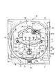
本実施形態における弾球式遊技機10の構成について、図面を参照しながら説明する。図1は、本実施形態における弾球式遊技機10の全体を示す斜視図である。   The configuration of the ball-type game machine 10 in the present embodiment will be described with reference to the drawings. FIG. 1 is a perspective view showing the entire ball-type game machine 10 in the present embodiment.

図1に示すように、弾球式遊技機10は、遊技場に弾球式遊技機10を設置するために設けられている外枠1と、外枠1の内側に開閉可能に設けられている前面枠(以下、前枠という)2と、正面側から見て液晶表示装置4の前面側に配備され、遊技部材が配設された遊技盤ベース19からなる遊技盤と、特定の情報を表示する液晶表示装置4とを具備する。なお、前枠2は、遊技盤の前面側に配設されている。本実施形態では、特定の情報の一例として、特定の画像を用いた説明を行う。この特定の画像は、液晶表示装置4上の表示領域に表示される(後述する図4参照)。   As shown in FIG. 1, the ball-type game machine 10 is provided in an outer frame 1 provided for installing the ball-type game machine 10 in a game hall, and can be opened and closed inside the outer frame 1. A front frame (hereinafter referred to as a front frame) 2, a game board composed of a game board base 19 provided on the front side of the liquid crystal display device 4 as viewed from the front side and provided with game members, and specific information And a liquid crystal display device 4 for display. The front frame 2 is disposed on the front side of the game board. In the present embodiment, description is given using a specific image as an example of specific information. This specific image is displayed in a display area on the liquid crystal display device 4 (see FIG. 4 described later).

また、前枠2には、透明な部材によって形成されたタッチパネル3が配置されている。本実施形態では、一例として、前枠2のほぼ全面を覆うように、タッチパネル3が配置されているが、前枠2の一部の面を覆うように、タッチパネル3が配置されていても、本発明は同様に適用できる。ここで、タッチパネル3は、液晶表示装置4に表示される特定の画像を、遊技盤ベース19を介して遊技者が視認できるような、遊技盤ベース19の前面側に配置されたスイッチ手段である。言い換えると、タッチパネル3は、前枠2の前面側に配置され、遊技者による所定の操作(押圧操作)によりスイッチとして働く手段である。後に詳述するように、遊技者が、タッチパネル3の所定位置を押圧することにより、押圧された位置が検出される。   A touch panel 3 formed of a transparent member is disposed on the front frame 2. In the present embodiment, as an example, the touch panel 3 is disposed so as to cover almost the entire front frame 2, but even if the touch panel 3 is disposed so as to cover a part of the front frame 2, The present invention is equally applicable. Here, the touch panel 3 is switch means arranged on the front side of the game board base 19 so that a player can visually recognize a specific image displayed on the liquid crystal display device 4 via the game board base 19. . In other words, the touch panel 3 is a means that is disposed on the front side of the front frame 2 and functions as a switch by a predetermined operation (pressing operation) by the player. As will be described in detail later, when the player presses a predetermined position on the touch panel 3, the pressed position is detected.

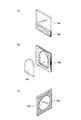
図2(a)乃至(c)は、遊技盤ベース19の構成を示す図である。図2(a)乃至(c)に示すように、遊技盤ベース19の少なくとも一部は、液晶表示装置4に表示される特定の画像を正面側から見て視認可能な透過部材19aで形成されている。この透過部材は、無色透明のアクリル樹脂材、ボリカーボネート樹脂又はポリアリレート樹脂等の合成樹脂で形成することができる。   2A to 2C are diagrams showing the configuration of the game board base 19. As shown in FIGS. 2A to 2C, at least a part of the game board base 19 is formed of a transmissive member 19a that allows a specific image displayed on the liquid crystal display device 4 to be seen from the front side. ing. This transmissive member can be formed of a synthetic resin such as a colorless and transparent acrylic resin material, a polycarbonate resin, or a polyarylate resin.

図2(a)に示すように、遊技盤ベース19は、透過部材19aが液晶表示装置4の一部又は全体を覆うような位置に配設され、当該透過部材19aの底部と木製部材19bの上部とが接合することにより構成される。また、図2(b)に示すように、遊技盤ベース19は、木製部材19bの中心部に設けられた穴に透過部材19aが嵌め込まれることにより構成されてもよい。さらに、図2(c)に示すように、遊技盤ベース19は、透明な部材の片面側にある19cの部分を非透明にマスキング(塗装、印刷等)して19aの部分のみを透明とすることにより構成されてもよい。   As shown in FIG. 2A, the game board base 19 is disposed at a position where the transmissive member 19a covers a part or the whole of the liquid crystal display device 4, and the bottom of the transmissive member 19a and the wooden member 19b are arranged. It is configured by joining the upper part. Moreover, as shown in FIG.2 (b), the game board base 19 may be comprised by inserting the permeation | transmission member 19a in the hole provided in the center part of the wooden member 19b. Further, as shown in FIG. 2 (c), the game board base 19 masks (paints, prints, etc.) the portion 19c on one side of the transparent member so that only the portion 19a is transparent. May be configured.

なお、前枠2の少なくとも一部も、液晶表示装置4に表示される特定の画像を正面側から見て視認可能な透過部材19aで形成されている。   Note that at least a part of the front frame 2 is also formed of a transmissive member 19a that allows a specific image displayed on the liquid crystal display device 4 to be viewed from the front side.

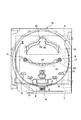
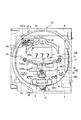
図3は、遊技盤ベース19に配設された遊技部材の配置関係を示す図である。遊技部材には、始動口6と、大入賞口8と、風車15と、アウト口16と、一般入賞口18と、遊技球誘導部材22とが含まれる。これらの遊技部材は、遊技盤ベース19の裏側にある液晶表示装置4に表示される画像を、正面側から見て透過可能な透過部材から構成される。   FIG. 3 is a diagram showing an arrangement relationship of the game members arranged on the game board base 19. The game members include a start port 6, a big winning port 8, a windmill 15, an out port 16, a general winning port 18, and a game ball guiding member 22. These gaming members are constituted by a transmissive member that can transmit an image displayed on the liquid crystal display device 4 on the back side of the game board base 19 when viewed from the front side.

始動口6は、当該始動口6に遊技球が入球すると大当り判定用の乱数値及び大当り図柄決定用の乱数値などが抽出されるように構成されている。大入賞口8は、特定領域(いわゆるVゾーン)と一般領域とを具備し、大当り判定用の乱数値に基づく大当り判定の結果に応じ、所定の設定に従って開閉するように制御される。   The starting port 6 is configured such that when a game ball enters the starting port 6, a random value for determining a big hit, a random value for determining a big hit symbol, and the like are extracted. The jackpot 8 includes a specific area (so-called V zone) and a general area, and is controlled to open and close according to a predetermined setting according to the result of the jackpot determination based on the random number value for the jackpot determination.

一般入賞口18は、当該一般入賞口18に遊技球が入球すると所定数(例えば、15個)の遊技球(賞球)が払い出されるように構成されている。アウト口16は、始動口12や大入賞口13や一般入賞口18などのいずれにも入球しなかった遊技球を受け入れる。風車15は、回転可能に構成され、遊技球の流下方向を変更するものである。   The general winning opening 18 is configured such that when a game ball enters the general winning opening 18, a predetermined number (for example, 15) of gaming balls (prize balls) are paid out. The out port 16 receives game balls that have not entered any of the starting port 12, the big winning port 13, the general winning port 18, and the like. The windmill 15 is configured to be rotatable, and changes the flow direction of the game ball.

遊技球誘導部材22は、遊技球の流下方向を大きく変化させるものであり、天通路23とステージ29とから構成される。天通路23は、遊技球が流下可能な遊技領域の上方に位置するように配設され、遊技盤ベース19の面に対して直角に立設された壁体から構成される。この天通路23の壁体は、当該天通路23の中心部が上方に突出されており、当該上方に突出された部分が屋根状に形成されている。また、この天通路23の壁体には、当該壁体に当接した遊技球を下方に誘導する切欠き部28が配設されている。   The game ball guiding member 22 largely changes the flow direction of the game ball, and includes a top passage 23 and a stage 29. The ceiling passage 23 is arranged so as to be positioned above a game area where game balls can flow down, and is constituted by a wall body standing upright to the surface of the game board base 19. In the wall of the ceiling passage 23, the central portion of the ceiling passage 23 protrudes upward, and the portion protruding upward is formed in a roof shape. Further, a notch portion 28 for guiding the game ball in contact with the wall body downward is disposed on the wall body of the ceiling passage 23.

ステージ29は、当該遊技領域の下方に位置するように配設され、遊技盤ベース19の面に対して直角に立設された壁体から構成される。このステージ29の壁体は、当該ステージ29の中心部が下方に突出されており、当該下方に突出された内壁面には遊技球を下方に誘導する切欠き部32が配設されている。   The stage 29 is disposed so as to be positioned below the game area, and is configured by a wall body standing upright at a right angle to the surface of the game board base 19. In the wall of the stage 29, the center portion of the stage 29 protrudes downward, and a notch 32 for guiding the game ball downward is provided on the inner wall surface protruding downward.

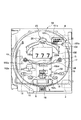
液晶表示装置4は、特定の画像を表示するものである。例えば、液晶表示装置4は、複数の特定の画像(特別図柄、演出画像、遊技データに関する画像、店員呼び出しのための画像、遊技説明情報に関する画像)を表示することができる。図4は、液晶表示装置4において、各表示領域内に表示される各種の画像を示す図である。具体的には、液晶表示装置4は、図4に示すように、第1の所定の表示領域(液晶表示装置4の表示領域)100内において、特別図柄の変動表示や、演出画像の表示を行う。   The liquid crystal display device 4 displays a specific image. For example, the liquid crystal display device 4 can display a plurality of specific images (special symbols, effect images, images relating to game data, images for calling store clerks, images relating to game description information). FIG. 4 is a diagram showing various images displayed in each display area in the liquid crystal display device 4. Specifically, as shown in FIG. 4, the liquid crystal display device 4 displays special symbol variation display and effect image display in the first predetermined display region (display region of the liquid crystal display device 4) 100. Do.

この第1の所定の表示領域を、以下、演出表示領域100という。また、液晶表示装置4は、図4に示すように、第2の所定の表示領域101(液晶表示装置4の表示領域)内において、大当たり回数や変動回数などの遊技データの表示や、店員呼び出しのための表示を行う。この第2の所定の表示領域を、以下、呼び出し用表示領域101という。また、液晶表示装置4は、図4に示すように、第3の所定の表示領域102(液晶表示装置4の表示領域)内において、遊技内容の説明を示す複数の遊技説明情報のうち、少なくとも1つの遊技説明情報に基づいた表示を行う。本実施形態では、一例として、第3の所定の表示領域102内において、複数の遊技説明情報のうち、1つの遊技説明情報に基づいた表示が行われる場合の説明を行う。この第3の所定の表示領域を、以下、遊技説明情報表示領域102という。   The first predetermined display area is hereinafter referred to as an effect display area 100. In addition, as shown in FIG. 4, the liquid crystal display device 4 displays game data such as the number of jackpots and the number of fluctuations, and calls the store clerk in the second predetermined display area 101 (display area of the liquid crystal display device 4). For the display. The second predetermined display area is hereinafter referred to as a call display area 101. Further, as shown in FIG. 4, the liquid crystal display device 4 has at least among a plurality of game explanation information indicating explanation of game contents in the third predetermined display area 102 (display area of the liquid crystal display apparatus 4). Display based on one game description information. In the present embodiment, as an example, a description will be given of a case where display based on one game description information among a plurality of game description information is performed in the third predetermined display area 102. Hereinafter, this third predetermined display area is referred to as a game explanation information display area 102.

後述するように、本実施形態では、演出表示領域100、呼び出し用表示領域101、遊技説明情報表示領域102の位置の変更や、演出表示領域100、呼び出し用表示領域101、遊技説明情報表示領域102の大きさの変更が可能である。   As will be described later, in the present embodiment, the positions of the effect display area 100, the call display area 101, and the game explanation information display area 102 are changed, and the effect display area 100, the call display area 101, and the game explanation information display area 102 are displayed. The size of can be changed.

そして、液晶表示装置4は、演出表示領域100内の所定の位置(例えば、図4に示す左上の角の位置)に、当該演出表示領域100を指定し、その位置を変更するための指定ボタン画像100aを表示し、演出表示領域100内の所定の位置(例えば、図4に示す右下の角の位置)に、当該演出表示領域100の大きさを変更させるための変更ボタン画像100bを表示し、演出表示領域100を囲むための枠画像100cを表示する。呼び出し用表示領域101、遊技説明情報表示領域102においても、同様にして、指定ボタン画像101a、102aや、変更ボタン画像101b、102b、枠画像101c、102cが表示される。   Then, the liquid crystal display device 4 designates the effect display area 100 at a predetermined position (for example, the position of the upper left corner shown in FIG. 4) in the effect display area 100, and a designation button for changing the position. An image 100a is displayed, and a change button image 100b for changing the size of the effect display area 100 is displayed at a predetermined position in the effect display area 100 (for example, the position of the lower right corner shown in FIG. 4). Then, a frame image 100c for enclosing the effect display area 100 is displayed. Similarly, in the call display area 101 and the game explanation information display area 102, designated button images 101a and 102a, change button images 101b and 102b, and frame images 101c and 102c are displayed.

ここで、遊技説明情報表示領域102においては、複数の遊技説明情報のうち、いずれかの遊技説明情報を指定するための説明情報指定ボタンが表示される。具体的な一例としては、遊技説明情報表示領域102においては、遊技説明情報が示された複数の頁からなる小冊子の所定の頁が開かれた表示態様が表示される。そして、遊技説明情報表示領域102においては、例えば、図4に示すように、頁を進めるための頁めくりボタン画像102dが表示されるとともに、頁を戻すための頁戻りボタン画像102eが表示される。   Here, in the game explanation information display area 102, an explanation information designation button for designating any one of the plurality of game explanation information is displayed. As a specific example, the game description information display area 102 displays a display mode in which a predetermined page of a booklet including a plurality of pages on which game description information is displayed is opened. In the game explanation information display area 102, for example, as shown in FIG. 4, a page turning button image 102d for advancing the page and a page return button image 102e for returning the page are displayed. .

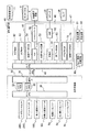
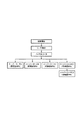
図5は、本実施形態における弾球式遊技機10の制御部を示すブロック図である。図5に示すように、弾球式遊技機10の制御部は、主制御回路30と副制御回路40と払出・発射制御回路80とにより構成される。主制御回路30は、メインCPU31と、メインROM32と、メインRAM33と、シリアル通信用IC36とを具備する。   FIG. 5 is a block diagram illustrating a control unit of the ball and ball game machine 10 according to the present embodiment. As shown in FIG. 5, the control unit of the ball-type game machine 10 includes a main control circuit 30, a sub-control circuit 40, and a payout / launch control circuit 80. The main control circuit 30 includes a main CPU 31, a main ROM 32, a main RAM 33, and a serial communication IC 36.

また、主制御回路30には、大入賞口13に具備される特定領域(Vゾーン)に入球した遊技球を計数するV・カウントスイッチ28Sと、大入賞口13に具備される一般領域に入球した遊技球を計数するカウントスイッチ29Sと、一般入賞口18に遊技球が入球したことを検出する一般入賞球スイッチ18Sと、始動口6を遊技球が通過したことを検出する始動入賞球スイッチ6Sと、始動口6の羽根を開閉する始動口ソレノイド6aと、大入賞口8の扉を開閉する大入賞口ソレノイド8aと、大入賞口8に入球した遊技球を特定領域と一般領域とに振り分けるシーソーを駆動するシーソーソレノイド8bと、遊技盤上の遊技領域に遊技球を発射する制御又は所定数の遊技球を払い出す制御を実行する払出・発射制御回路80とが接続されている。   Further, the main control circuit 30 includes a V / count switch 28S for counting game balls that have entered a specific area (V zone) provided in the special winning opening 13, and a general area provided in the special winning opening 13. A count switch 29S for counting the number of game balls entered, a general prize ball switch 18S for detecting that a game ball has entered the general prize opening 18, and a start prize for detecting that the game ball has passed through the start slot 6. The ball switch 6S, the start opening solenoid 6a for opening and closing the blades of the start opening 6, the large winning opening solenoid 8a for opening and closing the door of the large winning opening 8, and the game ball that has entered the large winning opening 8 as a specific area A seesaw solenoid 8b that drives a seesaw to be distributed to an area is connected to a payout / firing control circuit 80 that executes a control for launching a game ball to a game area on the game board or a control for paying out a predetermined number of game balls. ing.

メインCPU31は、遊技の進行を制御する遊技制御手段である。具体的には、メインCPU31は、遊技の進行に伴って行う各種の処理、例えば、(a)大当たりの判定処理、(b)液晶表示装置4に特別図柄の変動表示を開始させる処理などを実行する。   The main CPU 31 is game control means for controlling the progress of the game. Specifically, the main CPU 31 executes various processes performed as the game progresses, for example, (a) a jackpot determination process, (b) a process for causing the liquid crystal display device 4 to start a variable symbol display. To do.

メインROM32は、大当たり判定を実行するための判定テーブルを記憶している。また、メインROM32は、主制御回路30における各処理を制御するためのプログラムなどを記憶している。   The main ROM 32 stores a determination table for executing a jackpot determination. The main ROM 32 stores a program for controlling each process in the main control circuit 30.

メインRAM33は、大当り判定用の乱数値及び大当り図柄決定用の乱数値を含む始動記憶をしている。また、メインRAM33は、SRAMなどにより構成され、普通図柄始動記憶をも記憶している。   The main RAM 33 stores start-up memory including a random number for determining the big hit and a random value for determining the big hit. The main RAM 33 is composed of an SRAM or the like, and also stores a normal symbol start memory.

副制御回路40は、弾球式遊技機10の各種演出など制御するものであり、サブCPU41と、サブROM42と、サブRAM43と、画像処理回路45と、音処理回路46と、ランプ処理回路47とを具備する。サブRAM43は、主制御回路30から受信した各種コマンドを記憶する。   The sub control circuit 40 controls various effects of the ball-type game machine 10, and includes a sub CPU 41, a sub ROM 42, a sub RAM 43, an image processing circuit 45, a sound processing circuit 46, and a ramp processing circuit 47. It comprises. The sub RAM 43 stores various commands received from the main control circuit 30.

サブROM42は、遊技の進行に関連する情報を記憶する記憶手段(第一記憶手段)である。具体的には、サブROM42には、例えば、特別図柄の変動表示開始に対応づけられた特別図柄の変動表示パターンなどが記憶されている。   The sub ROM 42 is storage means (first storage means) that stores information related to the progress of the game. Specifically, the sub ROM 42 stores, for example, a special symbol variable display pattern associated with the start of special symbol variable display.

サブROM42は、副制御回路40における各処理を制御するためのプログラム、指定ボタン画像に関する情報、変更ボタン画像に関する情報、枠画像に関する情報、頁めくりボタン画像に関する情報、頁戻しボタン画像に関する情報、遊技内容の説明を示す複数の遊技説明情報を記憶する記憶手段(第二記憶手段)でもある。   The sub-ROM 42 is a program for controlling each process in the sub-control circuit 40, information about the designated button image, information about the change button image, information about the frame image, information about the page turning button image, information about the page return button image, game It is also a storage means (second storage means) for storing a plurality of game explanation information indicating the explanation of the contents.

画像処理回路45は、サブCPU41からのコマンドに応じて、液晶表示装置4に特別図柄の変動表示、それに伴なう演出表示などの各種の表示を行わせる。この画像処理回路45は、各種の画像データを記憶する画像データROM54と、画像データROM54に記憶されている画像データに基づいて特別図柄の変動表示情報などの画像情報を生成するVDP(Video Display Processor)51と、VDP51により生成された画像情報をアナログ信号に変換するD/Aコンバータ52と、電源投入時や異常時に各種設定を初期値に戻す初期リセット回路53とを具備する。図6乃至図15は、本実施形態のサブCPU41により行われる表示制御処理の説明を補足するための図である。   In response to a command from the sub CPU 41, the image processing circuit 45 causes the liquid crystal display device 4 to perform various displays such as a special symbol variation display and an accompanying effect display. The image processing circuit 45 includes an image data ROM 54 that stores various image data, and a VDP (Video Display Processor) that generates image information such as variation display information of special symbols based on the image data stored in the image data ROM 54. ) 51, a D / A converter 52 that converts image information generated by the VDP 51 into an analog signal, and an initial reset circuit 53 that returns various settings to initial values when the power is turned on or abnormal. 6 to 15 are diagrams for supplementing the description of the display control process performed by the sub CPU 41 of the present embodiment.

サブCPU41は、遊技中の所定のタイミング(例えば、メインCPU31による初期化処理が行われた後)で、指定ボタン画像に関する情報(例えば、指定ボタン画像パターン)、変更ボタン画像に関する情報(例えば、変更ボタン画像パターン)、枠画像に関する情報(例えば、枠画像パターン)、頁めくりボタン画像に関する情報(例えば、頁めくりボタン画像パターン)、頁戻しボタン画像に関する情報(例えば、頁戻しボタン画像パターン)、複数の遊技説明情報のうち、所定の遊技説明情報をサブROM42から読み出す。   The sub CPU 41, at a predetermined timing during the game (for example, after the initialization process is performed by the main CPU 31), information regarding the specified button image (for example, the specified button image pattern), information regarding the change button image (for example, change) Button image pattern), information about a frame image (for example, a frame image pattern), information about a page turning button image (for example, a page turning button image pattern), information about a page back button image (for example, a page back button image pattern), a plurality of Among the game description information, predetermined game description information is read from the sub ROM 42.

そして、サブCPU41は、VDP51に対して、以下のような指示を行う。この指示とは、例えば、指定ボタン画像パターン、変更ボタン画像パターン、枠画像パターンに基づいて、所定の演出表示領域100内の所定領域に、指定ボタン画像、枠画像、変更ボタン画像を、例えば、図4に示すような配置で、表示させるように、液晶表示装置4を制御するような指示である。VDP51は、上記指示に基づいて、画像データROM54から、必要な画像データを取得して、指定ボタン画像、枠画像、変更ボタン画像を生成し、液晶表示装置4に、所定の演出表示領域100内の所定領域に、指定ボタン画像、枠画像、変更ボタン画像を、例えば、図4に示すような配置で、表示させる。   Then, the sub CPU 41 instructs the VDP 51 as follows. This instruction refers to, for example, a specified button image, a frame image, and a change button image in a predetermined area in a predetermined effect display area 100 based on a specified button image pattern, a change button image pattern, and a frame image pattern. The instruction is to control the liquid crystal display device 4 to display in the arrangement as shown in FIG. Based on the above instruction, the VDP 51 acquires necessary image data from the image data ROM 54, generates a specified button image, a frame image, and a change button image, and displays them in the predetermined effect display area 100 in the liquid crystal display device 4. The designated button image, the frame image, and the change button image are displayed in the predetermined area, for example, in an arrangement as shown in FIG.

そして、サブCPU41による指示に基づいて、VDP51は、液晶表示装置4に、所定の演出表示領域100内に、特別図柄の変動表示、演出画像の表示を行わせる。   Then, based on the instruction from the sub CPU 41, the VDP 51 causes the liquid crystal display device 4 to perform special symbol variation display and display of the effect image in the predetermined effect display area 100.

また、同様にして、サブCPU41は、VDP51に対して、上述したような指示を行うことにより、VDP51は、液晶表示装置4に、所定の呼び出し用表示領域101内の所定領域に、指定ボタン画像、枠画像、変更ボタン画像を、例えば、図4に示すような配置で、表示させる。そして、サブCPU41による指示に基づいて、VDP51は、液晶表示装置4に、所定の呼び出し用表示領域101内に、遊技データの表示や、店員呼び出しのための表示を行わせる。   Similarly, the sub CPU 41 instructs the VDP 51 as described above, so that the VDP 51 causes the liquid crystal display device 4 to display a designated button image in a predetermined area in the predetermined call display area 101. The frame image and the change button image are displayed, for example, in an arrangement as shown in FIG. Then, based on an instruction from the sub CPU 41, the VDP 51 causes the liquid crystal display device 4 to display game data or display for calling a clerk in a predetermined call display area 101.

また、同様にして、サブCPU41は、VDP51に対して、上述したような指示(但し、この指示には、頁めくりボタン画像パターン、頁戻しボタン画像パターンが含まれる)を行うことにより、VDP51は、上記指示に基づいて、画像データROM54から、必要な画像データを取得して、指定ボタン画像、枠画像、変更ボタン画像、頁めくりボタン画像、頁戻りボタン画像を生成し、液晶表示装置4に、所定の呼び出し用表示領域101内の所定領域に、指定ボタン画像、枠画像、変更ボタン画像、頁めくりボタン画像、頁戻りボタン画像を、例えば、図4に示すような配置で、表示させる。   Similarly, the sub CPU 41 gives an instruction as described above to the VDP 51 (however, this instruction includes a page turning button image pattern and a page returning button image pattern). Based on the above instruction, necessary image data is acquired from the image data ROM 54, and a designation button image, a frame image, a change button image, a page turning button image, and a page return button image are generated, and the liquid crystal display device 4 The designated button image, the frame image, the change button image, the page turning button image, and the page return button image are displayed in a predetermined area within the predetermined calling display area 101, for example, in an arrangement as shown in FIG.

また、サブCPU41は、VDP51に対して、以下のような指示を行う。この指示とは、遊技説明情報表示領域102内の所定領域に、所定の遊技説明情報に関する画像を表示させるように、液晶表示装置4を制御するような指示である。VDP51は、上記指示に基づいて、所定の遊技説明情報に関する画像を生成し、液晶表示装置4に、所定の遊技説明情報表示領域102内の所定領域に、所定の遊技説明情報に関する画像を表示させる。   The sub CPU 41 instructs the VDP 51 as follows. This instruction is an instruction to control the liquid crystal display device 4 so that an image related to predetermined game description information is displayed in a predetermined area in the game description information display area 102. Based on the above instruction, the VDP 51 generates an image related to the predetermined game description information, and causes the liquid crystal display device 4 to display an image related to the predetermined game description information in a predetermined area in the predetermined game description information display area 102. .

サブCPU41には、タッチパネル3が接続されている。タッチパネル3は、遊技盤の遊技領域内の位置と関連する、遊技者による所定の操作を検出するスイッチ手段を構成する。具体的には、遊技者がタッチパネル3内の所定位置を押圧する操作を行うと、タッチパネル3は、上記押圧操作を検出し、押圧操作を示す信号を、インターフェース部(図示せず)を介して、サブCPU41に送る。この際、タッチパネル3は、当該押圧操作が行われたタッチパネルの位置を示す信号もサブCPU41に送る。   The touch panel 3 is connected to the sub CPU 41. The touch panel 3 constitutes switch means for detecting a predetermined operation by the player related to the position in the game area of the game board. Specifically, when the player performs an operation of pressing a predetermined position in the touch panel 3, the touch panel 3 detects the pressing operation and sends a signal indicating the pressing operation via an interface unit (not shown). To the sub CPU 41. At this time, the touch panel 3 also sends a signal indicating the position of the touch panel where the pressing operation is performed to the sub CPU 41.

このタッチパネル3内の所定の位置とは、指定ボタン画像、変更ボタン画像、頁めくりボタン画像、頁戻りボタン画像が表示されている位置である。   The predetermined position in the touch panel 3 is a position where a designation button image, a change button image, a page turning button image, and a page return button image are displayed.

サブCPU41は、タッチパネル3により検出された遊技者による所定の操作に基づいて、遊技盤の遊技領域内の所定の位置を検出する位置検出手段である。言い換えると、サブCPU41は、タッチパネル3において、遊技者により所定の操作が行われた位置を検出する。なお、上記位置検出手段は、サブCPU41と独立した構成であってもよい。   The sub CPU 41 is position detecting means for detecting a predetermined position in the game area of the game board based on a predetermined operation by the player detected by the touch panel 3. In other words, the sub CPU 41 detects a position on the touch panel 3 where a predetermined operation is performed by the player. The position detection unit may be configured independently of the sub CPU 41.

具体的には、サブCPU41は、タッチパネル3から送られてきた押圧操作を示す信号と、当該押圧操作が行われたタッチパネル3の位置を示す信号とに基づいて、遊技者による所定の操作が行われた、遊技領域内の所定の位置を検出する。   Specifically, the sub CPU 41 performs a predetermined operation by the player based on a signal indicating the pressing operation sent from the touch panel 3 and a signal indicating the position of the touch panel 3 on which the pressing operation is performed. The predetermined position in the game area is detected.

サブCPU41は、液晶表示装置4における表示動作を制御する表示制御手段である。具体的には、サブCPU41は、検出した所定の位置に、特定の画像を表示するように、液晶表示装置4を制御する表示制御手段である。   The sub CPU 41 is display control means for controlling the display operation in the liquid crystal display device 4. Specifically, the sub CPU 41 is a display control unit that controls the liquid crystal display device 4 so as to display a specific image at a detected predetermined position.

具体的には、サブCPU41は、特定の情報の表示(例えば、店員呼び出しのための表示)を、サブCPU41により検出された所定の位置に、移動させるように、液晶表示装置4を制御する。また、サブCPU41は、液晶表示装置4の遊技説明情報表示領域102に表示されている少なくとも1つの遊技説明情報を、サブCPU41により検出された所定の位置に、表示させるように、前記表示手段を制御する。   Specifically, the sub CPU 41 controls the liquid crystal display device 4 to move the display of specific information (for example, display for calling a clerk) to a predetermined position detected by the sub CPU 41. Further, the sub CPU 41 displays the display means so that at least one game description information displayed in the game description information display area 102 of the liquid crystal display device 4 is displayed at a predetermined position detected by the sub CPU 41. Control.

例えば、サブCPU41は、液晶表示装置4上の所定領域(演出表示領域100)以外の領域(遊技説明情報表示領域102)に表示されている少なくとも1つの遊技説明情報を、検出した所定の位置に、表示させるように、液晶表示装置4を制御する。また、例えば、サブCPU41は、所定の呼び出しのための表示(店員呼び出しのための表示)を、検出した所定の位置に、表示させるように、液晶表示装置4を制御する。この処理の詳細な説明は、以下のとおりである。   For example, the sub CPU 41 places at least one game description information displayed in an area (game description information display area 102) other than the predetermined area (effect display area 100) on the liquid crystal display device 4 at the detected predetermined position. The liquid crystal display device 4 is controlled so as to be displayed. Further, for example, the sub CPU 41 controls the liquid crystal display device 4 to display a display for a predetermined call (display for calling a clerk) at a detected predetermined position. A detailed description of this process is as follows.

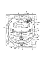
例えば、図4に示すように、遊技中において、液晶表示装置4は、所定の演出表示領域100内において、指定ボタン画像100a、変更ボタン画像100b、枠画像100cを表示するとともに、特別図柄の変動表示、演出画像の表示を行っているとする。遊技者が、タッチパネル3上の、指定ボタン画像100aが表示されている位置を押圧すると、押圧操作を示す信号及び当該押圧操作が行われたタッチパネル3の位置を示す信号がサブCPU41に送られる。サブCPU41は、送られてきた信号に基づいて、演出表示領域100の位置の変更が行われることを認識し、次の押圧操作を示す信号などが来るのを待つ動作を行う。   For example, as shown in FIG. 4, during the game, the liquid crystal display device 4 displays a designated button image 100a, a change button image 100b, and a frame image 100c in a predetermined effect display area 100, and changes in special symbols. It is assumed that display and effect images are being displayed. When the player presses a position on the touch panel 3 where the designation button image 100a is displayed, a signal indicating the pressing operation and a signal indicating the position of the touch panel 3 where the pressing operation is performed are sent to the sub CPU 41. The sub CPU 41 recognizes that the change of the position of the effect display area 100 is performed based on the transmitted signal, and performs an operation of waiting for a signal indicating the next pressing operation.

そして、遊技者が、タッチパネル3上の任意の位置を押圧すると、押圧操作を示す信号及び当該押圧操作が行われたタッチパネル3の位置を示す信号が、サブCPU41に送られる。サブCPU41は、押圧操作を示す信号及び当該押圧操作が行われたタッチパネル3の位置を示す信号に基づいて、押圧操作が行われた遊技領域内の位置を検出する。そして、サブCPU41は、検出した遊技領域内の位置に、指定ボタン画像100aが表示されるように、演出表示領域100内の各画像(指定ボタン画像、枠画像、変更ボタン画像、特別図柄、演出画像)の位置を変更するように、VDP51に指示する。VDP51に指示に基づいて、液晶表示装置4は、サブCPU41により検出された遊技領域内の位置に、指定ボタン画像が表示されるように、演出表示領域100内に表示される各画像(指定ボタン画像、枠画像、変更ボタン画像、特別図柄、演出画像)の位置を変更する。この際、演出表示領域100の大きさ、演出表示領域内における各画像の配置は、変更されない。即ち、上述の動作により、演出表示領域100内の各画像は、平行移動されることになる。上述の動作により、例えば、演出表示領域100内の各画像は、図4に示す位置から、図6に示す位置に平行移動される。   When the player presses an arbitrary position on the touch panel 3, a signal indicating the pressing operation and a signal indicating the position of the touch panel 3 on which the pressing operation is performed are sent to the sub CPU 41. The sub CPU 41 detects a position in the game area where the pressing operation is performed based on a signal indicating the pressing operation and a signal indicating the position of the touch panel 3 where the pressing operation is performed. Then, the sub CPU 41 displays each image (designated button image, frame image, change button image, special symbol, effect, etc.) in the effect display area 100 so that the designated button image 100a is displayed at the detected position in the game area. The VDP 51 is instructed to change the position of the image. Based on the instruction to the VDP 51, the liquid crystal display device 4 displays each image (designated button) displayed in the effect display area 100 so that the designated button image is displayed at the position in the game area detected by the sub CPU 41. The position of the image, frame image, change button image, special symbol, effect image) is changed. At this time, the size of the effect display area 100 and the arrangement of the images in the effect display area are not changed. That is, by the above-described operation, each image in the effect display area 100 is translated. By the above-described operation, for example, each image in the effect display area 100 is translated from the position shown in FIG. 4 to the position shown in FIG.

所定の呼び出し用表示領域101内の各画像の位置の変更、所定の遊技説明情報表示領域102内の各画像の位置の変更についても、上述の動作の説明が適用される(図7,図8参照)。   The above description of the operation is also applied to the change of the position of each image in the predetermined call display area 101 and the change of the position of each image in the predetermined game explanation information display area 102 (FIGS. 7 and 8). reference).

ここで、サブCPU41は、液晶表示装置4の表示領域内における、演出表示領域100の位置情報、呼び出し用表示領域101の位置情報、遊技説明情報表示領域102の位置情報を管理している。   Here, the sub CPU 41 manages the position information of the effect display area 100, the position information of the calling display area 101, and the position information of the game explanation information display area 102 within the display area of the liquid crystal display device 4.

なお、タッチパネル3は、複数の特定の画像をそれぞれ表示するための所定の位置と関連する、遊技者による所定の押圧操作を検出し、サブCPU41は、タッチパネル3により検出された上記所定の押圧操作に基づいて、複数の特定の画像をそれぞれ表示するための所定の位置を検出した場合、サブCPU41は、検出された各所定の位置に、それぞれ、特定の画像を表示するように、液晶表示装置4を制御することもできる。   The touch panel 3 detects a predetermined pressing operation by the player, which is associated with a predetermined position for displaying a plurality of specific images, and the sub CPU 41 detects the predetermined pressing operation detected by the touch panel 3. The sub CPU 41 displays a specific image at each detected predetermined position when a predetermined position for displaying each of the plurality of specific images is detected based on the liquid crystal display device. 4 can also be controlled.

ここでいう複数の特定の画像とは、例えば、演出表示領域100内に表示される画像、呼び出し用表示領域101内に表示される画像、遊技説明情報表示領域103内に表示される画像のうち、少なくとも2つ以上の画像のことである。   The plurality of specific images referred to here are, for example, images displayed in the effect display area 100, images displayed in the call display area 101, and images displayed in the game description information display area 103. Means at least two images.

具体的には、遊技者による所定の演出表示領域100内の指定ボタン画像100aの押圧操作に基づいて、上述したようにして、所定の演出表示領域100内の各画像の位置の変更が行われ、遊技者による所定の呼び出し用表示領域101内の指定ボタン画像101aの押圧操作に基づいて、上述したようにして、所定の呼び出し用表示領域101内の各画像の位置の変更が行われ、遊技者による所定の遊技情報説明表示領域102内の指定ボタン画像102aの押圧操作に基づいて、上述したようにして、所定の遊技情報説明表示領域内の各画像の位置の変更が行われる。   Specifically, the position of each image in the predetermined effect display area 100 is changed as described above based on the pressing operation of the designation button image 100a in the predetermined effect display area 100 by the player. Based on the pressing operation of the designated button image 101a in the predetermined call display area 101 by the player, the position of each image in the predetermined call display area 101 is changed as described above. Based on the pressing operation of the designation button image 102a in the predetermined game information explanation display area 102 by the user, the position of each image in the predetermined game information explanation display area is changed as described above.

また、サブCPU41は、以下のような処理を行うこともできる。特定の画像(例えば、遊技説明情報に関する画像)が、サブCPU41により検出された位置を含む表示領域にて表示され(又は所定の呼び出しのための表示がサブCPU41により検出された位置を含む表示領域にて表示され)、タッチパネル3は、上記表示領域の大きさの変更に関する位置の情報に関する、遊技者による所定の押圧操作を検出し、サブCPU41は、タッチパネル3により検出された上記所定の操作に基づいて、上記表示領域の大きさの変更に関する位置の情報を検出した場合、検出された上記変更に関する位置の情報に基づいて、サブCPU41は、上記表示領域の大きさを変更するように、液晶表示装置4を制御することもできる。具体的な説明の一例は、以下のとおりである。   The sub CPU 41 can also perform the following processing. A specific image (for example, an image relating to game description information) is displayed in a display area including a position detected by the sub CPU 41 (or a display area including a position where a display for a predetermined call is detected by the sub CPU 41 The touch panel 3 detects a predetermined pressing operation by the player regarding the position information related to the change in the size of the display area, and the sub CPU 41 detects the predetermined operation detected by the touch panel 3. Based on the detected position information related to the change, the sub CPU 41 changes the size of the display area to detect the position information related to the change in the size of the display area. The display device 4 can also be controlled. An example of a specific description is as follows.

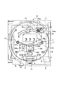
例えば、図4に示すように、液晶表示装置4は、所定の演出表示領域100内において、指定ボタン画像100a、変更ボタン画像100b、枠画像100cを表示するとともに、特別図柄の変動表示、演出画像の表示を行っているとする。遊技者が、タッチパネル3上の、変更ボタン画像100bが表示されている位置を押圧すると、押圧操作を示す信号及び当該押圧操作が行われたタッチパネル3の位置を示す信号がサブCPU41に送られ、サブCPU41は、演出表示領域100の大きさの変更が行われることを認識し、次の押圧操作を示す信号などが来るのを待つ動作を行う。   For example, as shown in FIG. 4, the liquid crystal display device 4 displays a designated button image 100 a, a change button image 100 b, and a frame image 100 c in a predetermined effect display area 100, and a special symbol variation display and effect image. Is displayed. When the player presses the position on the touch panel 3 where the change button image 100b is displayed, a signal indicating the pressing operation and a signal indicating the position of the touch panel 3 where the pressing operation is performed are sent to the sub CPU 41. The sub CPU 41 recognizes that the size of the effect display area 100 is changed, and performs an operation of waiting for a signal indicating the next pressing operation.

そして、遊技者が、タッチパネル3上の任意の位置を押圧すると、押圧操作を示す信号及び当該押圧操作が行われたタッチパネル3の位置を示す信号が、サブCPU41に送られる。サブCPU41は、送られてきた信号に基づいて、押圧操作が行われた遊技領域内の位置を検出する。そして、サブCPU41は、指定ボタン画像100aの表示位置を固定にしたままで、検出した位置に、変更ボタン画像100bが表示されるように、演出表示領域100の大きさ(枠画像100cの大きさ、特別図柄の大きさ、演出画像の大きさ)を変更するように、VDP51に指示する。VDP51の指示に基づいて、液晶表示装置4は、指定ボタン画像100aの表示位置を固定にしたままで、サブCPU41により検出された位置に、変更ボタン画像100bが表示されるように、演出表示領域の大きさ(枠画像100cの大きさ、特別図柄の大きさ、演出画像の大きさ)を変更する(図9参照)。   When the player presses an arbitrary position on the touch panel 3, a signal indicating the pressing operation and a signal indicating the position of the touch panel 3 on which the pressing operation is performed are sent to the sub CPU 41. The sub CPU 41 detects the position in the game area where the pressing operation is performed based on the transmitted signal. Then, the sub CPU 41 fixes the size of the effect display area 100 (the size of the frame image 100c) so that the change button image 100b is displayed at the detected position while the display position of the designation button image 100a is fixed. The VDP 51 is instructed to change the size of the special symbol and the size of the effect image. Based on the instruction from the VDP 51, the liquid crystal display device 4 keeps the display position of the designation button image 100a fixed, and the effect display area is displayed so that the change button image 100b is displayed at the position detected by the sub CPU 41. (The size of the frame image 100c, the size of the special symbol, the size of the effect image) is changed (see FIG. 9).

所定の呼び出し用表示領域101の大きさの変更、所定の遊技説明情報表示領域102の大きさの変更についても、上述の動作の説明が同様に適用される(図10,図11参照)。   The above description of the operation is similarly applied to the change of the size of the predetermined call display area 101 and the change of the size of the predetermined game description information display area 102 (see FIGS. 10 and 11).

また、サブCPU41は、以下のような処理を行うこともできる。液晶表示装置4は、複数の特定の画像を重ねて表示することが可能である。タッチパネル3は、複数の特定の画像がそれぞれ表示されている領域のうち、いずれかの領域内の位置に関する、遊技者による所定の押圧操作を検出し、サブCPU41は、タッチパネル3により検出された上記所定の押圧操作に基づいて、複数の特定の画像がそれぞれ表示されている領域のうち、いずれかの領域内の位置を検出した場合、サブCPU41は、液晶表示装置4で重ねて表示された複数の特定の画像のうち、検出された位置を含む領域に表示された特定の画像を、前面側に表示させる。具体的な説明の一例は、以下のとおりである。   The sub CPU 41 can also perform the following processing. The liquid crystal display device 4 can display a plurality of specific images in a superimposed manner. The touch panel 3 detects a predetermined pressing operation by the player regarding the position in any one of the areas in which a plurality of specific images are displayed, and the sub CPU 41 detects the above-described detection by the touch panel 3. When the position in any one of the areas where a plurality of specific images are respectively displayed is detected based on a predetermined pressing operation, the sub CPU 41 displays a plurality of overlapping images displayed on the liquid crystal display device 4. Among these specific images, the specific image displayed in the area including the detected position is displayed on the front side. An example of a specific description is as follows.

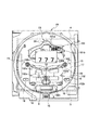
例えば、液晶表示装置4は、所定の演出表示領域100内において、指定ボタン画像100a、変更ボタン画像100b、枠画像100cを表示するとともに、特別図柄の変動表示、演出画像の表示を行っているとともに、所定の呼び出し用表示領域101内において、指定ボタン画像101a、変更ボタン画像101b、枠画像101cを表示するとともに、遊技データの表示や、店員呼び出しのための表示を行っている。この際、図12に示すように、所定の演出表示領域100と、所定の呼び出し用表示領域101は、所定の領域において、重なっており、上記所定の領域においては、演出表示領域100内の各画像が表示されているとする。   For example, the liquid crystal display device 4 displays a designated button image 100a, a change button image 100b, and a frame image 100c in a predetermined effect display area 100, and also displays a special symbol variation display and an effect image. The designated button image 101a, the change button image 101b, and the frame image 101c are displayed in the predetermined call display area 101, and the game data and the display for calling the store clerk are displayed. At this time, as shown in FIG. 12, the predetermined effect display area 100 and the predetermined call display area 101 overlap each other in the predetermined area. Assume that an image is displayed.

遊技者が、タッチパネル3上の、所定の呼び出し用表示領域101内の所定の位置(重なっている所定領域以外の領域)を押圧すると、押圧操作を示す信号及び当該押圧操作が行われたタッチパネル3の位置を示す信号がサブCPU41に送られる。   When the player presses a predetermined position (a region other than the overlapping predetermined region) in the predetermined call display area 101 on the touch panel 3, a signal indicating the pressing operation and the touch panel 3 on which the pressing operation has been performed. A signal indicating the position of is sent to the sub CPU 41.

サブCPU41は、送られてきた信号に基づいて、遊技領域内の押圧操作が行われた位置を検出し、管理している各表示領域の位置情報に基づいて、押圧操作が行われた位置に対応する表示領域が、演出表示領域100か、呼び出し用表示領域101か、遊技説明情報表示領域102であるかを判断する。ここでは、サブCPU41は、押圧操作が行われた位置に対応する表示領域が、呼び出し用表示領域101であると判断する。   The sub CPU 41 detects the position where the pressing operation is performed in the gaming area based on the transmitted signal, and at the position where the pressing operation is performed based on the positional information of each display area managed. It is determined whether the corresponding display area is the effect display area 100, the call display area 101, or the game explanation information display area 102. Here, the sub CPU 41 determines that the display area corresponding to the position where the pressing operation is performed is the calling display area 101.

そして、サブCPU41は、上記重なっている所定領域上において、呼び出し用表示領域101内の各画像を表示させるように、VDP51に指示する。VDP51の指示に基づいて、液晶表示装置4は、図13に示すように、上記重なっている所定領域上において、呼び出し用表示領域101内の各画像を表示する。   Then, the sub CPU 41 instructs the VDP 51 to display each image in the calling display area 101 on the overlapping predetermined area. Based on the instruction from the VDP 51, the liquid crystal display device 4 displays each image in the calling display area 101 on the overlapping predetermined area as shown in FIG.

演出表示領域100、呼び出し用表示領域101、遊技説明情報表示領域102のうち、いずれか2つの表示領域が重なっている場合、3つの全ての表示領域が重なっている場合についても、上述の動作が適用される。   Of the effect display area 100, the call display area 101, and the game description information display area 102, when any two display areas are overlapped, the above operation is performed even when all three display areas are overlapped. Applied.

また、サブCPU41は、メインCPU31によって進行する遊技に関連する、サブROM42に記憶された情報に基づいて、液晶表示装置4の所定領域(演出表示領域100)に、遊技の進行に関連する表示を液晶表示装置4に行わせるように制御する表示制御手段である。   Further, the sub CPU 41 displays a display related to the progress of the game in a predetermined area (effect display area 100) of the liquid crystal display device 4 based on the information stored in the sub ROM 42 related to the game progressed by the main CPU 31. Display control means for controlling the liquid crystal display device 4 to perform.

具体的には、例えば、メインCPU31により進行された遊技に関する処理が、例えば、特別図柄の変動表示開始処理の場合には、サブROM42に記憶された、特別図柄の変動表示開始に対応する特別図柄の変動表示パターンを取得し、VDP51に対して、演出表示領域100内に、変動表示パターンに従った変動表示を行わせるように指示する。VDP51は、液晶表示装置4上の演出表示領域100内に、変動表示パターンに従った特別図柄の変動表示を行わせる。   Specifically, for example, when the process related to the game progressed by the main CPU 31 is, for example, a special symbol variable display start process, the special symbol corresponding to the special symbol variable display start stored in the sub-ROM 42. Is obtained, and the VDP 51 is instructed to perform the variable display according to the variable display pattern in the effect display area 100. The VDP 51 causes the special symbol to change in accordance with the change display pattern in the effect display area 100 on the liquid crystal display device 4.

サブCPU41は、サブROM42に記憶された複数の遊技説明情報のうち、少なくとも1つの遊技説明情報に基づいた表示を、所定条件下で、切り替えて、液晶表示装置4上の所定領域(演出表示領域100)以外の領域(遊技説明情報表示領域102)に表示させる表示制御手段でもある。この処理の具体的な説明の一例は、以下のとおりである。以下に示す場合、「所定条件下で切り替える」とは、「遊技状態が変化したことを条件に切り替える」ことに対応する。   The sub CPU 41 switches the display based on at least one game description information among the plurality of game description information stored in the sub ROM 42 under a predetermined condition, and performs a predetermined area (effect display area) on the liquid crystal display device 4. It is also a display control means for displaying in an area other than (100) (game description information display area 102). An example of a specific description of this process is as follows. In the following cases, “switching under a predetermined condition” corresponds to “switching a game state to a condition”.

メインCPU31は、遊技において、現在の遊技状態を判定する遊技状態判定手段でもある。ここでいう遊技状態には、遊技中において、リーチ演出などの特有の演出が行われる状態も含まれる。遊技状態としては、例えば、通常遊技状態、リーチ状態、大当たり遊技状態などがある。そして、各遊技状態には、少なくとも1つの遊技説明情報が関連づけられている。具体的には、サブROM42に記憶された各遊技説明情報には、それぞれ、遊技状態が対応づけられている。   The main CPU 31 is also a game state determination means for determining the current game state in the game. The game state here includes a state in which a specific effect such as a reach effect is performed during the game. Examples of the gaming state include a normal gaming state, a reach state, a jackpot gaming state, and the like. Each game state is associated with at least one game description information. Specifically, each game description information stored in the sub ROM 42 is associated with a game state.

サブCPU41は、メインCPU31により判定された現在の遊技状態に関連する少なくとも1つの遊技説明情報に基づいた表示を、メインCPU31により判定される遊技状態の変化に基づいて、切り替えて、液晶表示装置4上の遊技説明情報表示領域102に表示させる。このサブCPU41による切り替え処理は、例えば、以下のようにして行われる。   The sub CPU 41 switches the display based on at least one game description information related to the current gaming state determined by the main CPU 31 based on the change of the gaming state determined by the main CPU 31, and the liquid crystal display device 4. It is displayed in the upper game explanation information display area 102. The switching process by the sub CPU 41 is performed as follows, for example.

例えば、図4に示すように、液晶表示装置4は、所定の遊技説明情報表示領域102内において、指定ボタン画像102a、変更ボタン画像102b、枠画像102c、頁めくりボタン画像102d,頁戻りボタン画像102e、所定の遊技説明情報を表示しているとする。ここでは、通常遊技状態に対応する遊技説明情報が表示されている。   For example, as shown in FIG. 4, the liquid crystal display device 4 includes a designated button image 102a, a change button image 102b, a frame image 102c, a page turning button image 102d, and a page return button image in a predetermined game explanation information display area 102. 102e, it is assumed that predetermined game description information is displayed. Here, game description information corresponding to the normal game state is displayed.

そして、メインCPU31は、現在の遊技状態は、リーチ状態であると判定し、リーチ状態であることを指定するコマンドをサブCPU41に送る。サブCPU41は、上記コマンドに基づいて、サブROM42から、リーチ状態に対応する遊技説明情報を取得する。そして、サブCPU41は、VDP51に、遊技説明情報表示領域102内に表示されていた遊技説明情報に代えて、リーチ状態に対応する遊技説明情報を、遊技説明情報表示領域102に表示させるように指示する。VDP51は、上記指示に基づいて、液晶表示装置4に、リーチ状態に対応する遊技説明情報を、遊技説明情報表示領域102に表示させる。   Then, the main CPU 31 determines that the current gaming state is a reach state, and sends a command to the sub CPU 41 to specify that it is a reach state. The sub CPU 41 acquires game description information corresponding to the reach state from the sub ROM 42 based on the command. Then, the sub CPU 41 instructs the VDP 51 to display game description information corresponding to the reach state in the game description information display area 102 instead of the game description information displayed in the game description information display area 102. To do. Based on the above instruction, the VDP 51 causes the liquid crystal display device 4 to display game explanation information corresponding to the reach state in the game explanation information display area 102.

図14は、リーチ状態に対応する遊技説明情報の一例を示す図である。この遊技説明情報においては、リーチフローが示されており、特別図柄の変動が開始されてから、リーチが発生した場合に、ノーマルリーチから、各スーパーリーチA〜D1に発展していく様子と、各スーパーリーチにおける大当たりの可能性を示す信頼度が示されている。なお、この遊技説明情報では、スーパーリーチD1が、さらに、スーパーリーチD2に発展する場合がある様子が示されている。また、この遊技説明情報において、各スーパーリーチの簡単な説明が示されていても良い。   FIG. 14 is a diagram illustrating an example of game description information corresponding to the reach state. In this game description information, the reach flow is shown, and when the reach occurs after the change of the special symbol is started, the state of developing from the normal reach to each of the super reach A to D1, Confidence indicating the potential for jackpots in super reach is shown. The game explanation information shows that the super reach D1 may further develop into the super reach D2. Further, in this game description information, a simple description of each super reach may be shown.

このようにして、遊技状態の変化に応じて、遊技説明情報表示領域102内の遊技説明情報は、切り替えられていく。   In this manner, the game description information in the game description information display area 102 is switched according to the change in the game state.

なお、サブCPU41による切り替え処理は、上述した方法以外で、以下のようにして行われてもよい。以下に示す場合、「所定条件下で切り替える」とは、「遊技者により、遊技説明情報が指定されたことを条件に切り替える」ことに対応する。   Note that the switching process by the sub CPU 41 may be performed as follows, in addition to the method described above. In the following case, “switching under a predetermined condition” corresponds to “switching under a condition that game description information is designated by the player”.

タッチパネル3及びサブCPU41は、所定の遊技説明情報を指定するための説明情報指定手段を構成する。そして、サブCPU41は、指定された少なくとも1つの遊技説明情報に基づいた表示を、指定された遊技説明情報の変化に基づいて、切り替えて、液晶表示装置4上の遊技説明情報表示領域102に表示させる。このサブCPU41による切り替え処理は、例えば、以下のようにして行われる。   The touch panel 3 and the sub CPU 41 constitute explanation information designating means for designating predetermined game explanation information. Then, the sub CPU 41 switches the display based on the specified at least one game description information based on the change of the specified game description information, and displays it on the game description information display area 102 on the liquid crystal display device 4. Let The switching process by the sub CPU 41 is performed as follows, for example.

サブROM42に記憶された各遊技説明情報には、それぞれ、頁情報が対応づけられている。そして、例えば、図4に示すように、液晶表示装置4は、所定の遊技説明情報表示領域102内において、指定ボタン画像102a、変更ボタン画像102b、枠画像102c、頁めくりボタン画像102d、頁戻りボタン画像102e、所定の遊技説明情報を表示しているとする。ここでは、通常遊技状態に対応する遊技説明情報が表示されている。   Each game description information stored in the sub ROM 42 is associated with page information. Then, for example, as shown in FIG. 4, the liquid crystal display device 4 includes a designated button image 102 a, a change button image 102 b, a frame image 102 c, a page turning button image 102 d, and a page return within a predetermined game explanation information display area 102. It is assumed that the button image 102e and predetermined game description information are displayed. Here, game description information corresponding to the normal game state is displayed.

遊技者が、タッチパネル3上の、頁めくりボタン画像102d又は頁戻りボタン画像102eが表示されている位置を押圧すると、押圧操作を示す信号及び当該押圧操作が行われたタッチパネル3の位置を示す信号がサブCPU41に送られる。サブCPU41は、押圧操作が行われたタッチパネル3の位置に基づいて、頁めくりボタンの押圧操作であるか、頁戻りボタンの押圧であるかを判断する。   When the player presses a position on the touch panel 3 where the page turning button image 102d or the page return button image 102e is displayed, a signal indicating the pressing operation and a signal indicating the position of the touch panel 3 where the pressing operation is performed. Is sent to the sub CPU 41. The sub CPU 41 determines whether the page turning button is pressed or the page return button is pressed based on the position of the touch panel 3 on which the pressing operation is performed.

サブCPU41は、現在の頁情報と、頁めくりボタンの押圧操作又は頁戻りボタンの押圧操作とに基づいて、遊技説明情報表示領域102内に表示する遊技説明情報の頁を算出する。そして、サブCPU41は、サブROM42から、算出した頁情報に対応する遊技説明情報を取得する。そして、サブCPU41は、VDP51に、遊技説明情報表示領域102内に表示されていた遊技説明情報に代えて、算出した頁情報に対応する遊技説明情報を、遊技説明情報表示領域102に表示させるように指示する。VDP51は、上記指示に基づいて、液晶表示装置4に、算出した頁情報に対応する遊技説明情報を、遊技説明情報表示領域102に表示させる。   The sub CPU 41 calculates a page of game description information to be displayed in the game description information display area 102 based on the current page information and a page turning button pressing operation or a page return button pressing operation. Then, the sub CPU 41 acquires game description information corresponding to the calculated page information from the sub ROM 42. Then, the sub CPU 41 causes the VDP 51 to display game description information corresponding to the calculated page information in the game description information display area 102 instead of the game description information displayed in the game description information display area 102. To instruct. Based on the above instruction, the VDP 51 causes the liquid crystal display device 4 to display game description information corresponding to the calculated page information in the game description information display area 102.

このようにして、頁めくりボタンの押圧又は頁戻りボタンの押圧が行われるごとに、遊技説明情報の指定の変化となり、この変化に応じて、遊技説明情報表示領域102内の遊技説明情報は、切り替えられていく。   In this way, each time the page turning button is pressed or the page return button is pressed, the designation of the game description information is changed. In accordance with this change, the game description information in the game description information display area 102 is It will be switched.

そして、遊技者が、頁めくりボタン画像102d又は頁戻りボタン画像102eが表示されている位置を押しては、表示される遊技説明情報を確認し、その動作を繰り返すことにより、遊技者の所望の遊技説明情報に基づいた表示が行われる。   Then, the player presses the position where the page turning button image 102d or the page return button image 102e is displayed, confirms the displayed game description information, and repeats the operation, thereby the player's desired game. Display based on the explanation information is performed.

また、図5に示すように、サブCPU41には、外部送信端子11が接続されている。外部送信端子11は、サブCPU41により検出された位置が、液晶表示装置4において特定の情報の表示(例えば、店員呼び出しのための表示)が行われる特定領域(例えば、所定の呼び出し用表示領域101)に対応した位置(タッチパネル3上における位置)である場合、遊技機10外部へ、上記特定の情報の表示に関連する信号を送信する送信手段である。   As shown in FIG. 5, the external transmission terminal 11 is connected to the sub CPU 41. The position of the external transmission terminal 11 detected by the sub CPU 41 is a specific area (for example, a predetermined call display area 101) where specific information is displayed on the liquid crystal display device 4 (for example, display for calling a clerk). ) Is a transmission means that transmits a signal related to the display of the specific information to the outside of the gaming machine 10.

この処理の具体的な説明の一例は、以下のとおりである。上記特定の情報の表示は、所定の呼び出し(例えば、店員呼び出しのための表示)の表示である。外部送信端子11は、上記所定の呼び出しの機能を実行できる装置に、上記所定の呼び出しの表示に関連する信号を送信する。   An example of a specific description of this process is as follows. The display of the specific information is a display of a predetermined call (for example, display for calling a clerk). The external transmission terminal 11 transmits a signal related to the display of the predetermined call to a device capable of executing the predetermined call function.

例えば、図4に示すように、液晶表示装置4は、所定の呼び出し用表示領域101内において、指定ボタン画像101a、変更ボタン画像101b、枠画像101cを表示するとともに、遊技データの表示や、店員呼び出しのための表示を行っているとする。遊技者が、タッチパネル3上の、店員呼び出しのための表示(図4に示す「CALL」)がされている位置を押圧すると、押圧操作を示す信号及び押圧操作が行われた位置を示す信号がサブCPU41に送られる。サブCPU41は、送られてきた信号に基づいて、押圧操作が行われた位置が上記呼び出しのための表示が行われる領域内の位置であると認識し、上記呼び出し機能を実行できる装置が解読できるような、上記呼び出しを示す信号を生成する。そして、サブCPU41から送られきた上記呼び出しを示す信号を、外部送信端子11は、上記呼び出しの機能を実行できる装置に送信する。   For example, as shown in FIG. 4, the liquid crystal display device 4 displays a designated button image 101a, a change button image 101b, and a frame image 101c in a predetermined call display area 101, and displays game data and a store clerk. Suppose you are displaying for a call. When the player presses a position on the touch panel 3 where a display for calling a clerk ("CALL" shown in FIG. 4) is displayed, a signal indicating the pressing operation and a signal indicating the position where the pressing operation is performed are displayed. It is sent to the sub CPU 41. The sub CPU 41 recognizes that the position where the pressing operation is performed is a position in the area where the display for calling is performed based on the transmitted signal, and can decode a device that can execute the calling function. A signal indicating the call is generated. Then, the external transmission terminal 11 transmits a signal indicating the call sent from the sub CPU 41 to a device capable of executing the call function.

これにより、上記呼び出しの機能を実行できる装置は、上記呼び出しを示す信号を解読して、上記呼び出し動作を実行する。本実施形態では、上記呼び出しの機能を実行できる装置としては、ホールコンピュータでもよいし、遊技機の設置島に配置された呼出表示装置であってもよく、特に、限定されない。   As a result, the device capable of executing the calling function decodes the signal indicating the calling and executes the calling operation. In the present embodiment, a device that can execute the above-described calling function may be a hall computer or a call display device arranged on an installation island of a gaming machine, and is not particularly limited.

また、サブCPU41は、検出した位置が、液晶表示装置4において特定の情報の表示(例えば、店員呼び出しのための表示)が行われる特定領域(例えば、所定の呼び出し用表示領域101)に対応した位置(タッチパネル3上における位置)である場合、上記特定の情報の表示を変更させるように、液晶表示装置4を制御する。この処理の詳細な説明は、以下のとおりである。   Further, the detected position of the sub CPU 41 corresponds to a specific area (for example, a predetermined call display area 101) where specific information is displayed on the liquid crystal display device 4 (for example, display for calling a clerk). In the case of the position (position on the touch panel 3), the liquid crystal display device 4 is controlled so as to change the display of the specific information. A detailed description of this process is as follows.

先ず、図4に示すように、液晶表示装置4は、所定の呼び出し用表示領域101内において、指定ボタン画像101a、変更ボタン画像101b、枠画像101cを表示するとともに、遊技データの表示及び店員呼び出しのための表示を、第1の表示パターンに従って、行っているとする。   First, as shown in FIG. 4, the liquid crystal display device 4 displays a designated button image 101a, a change button image 101b, and a frame image 101c in a predetermined call display area 101, and displays game data and calls a clerk. It is assumed that display for is performed according to the first display pattern.

そして、サブROM42には、遊技データの表示及び店員呼び出しの表示のための第2の表示パターン(第1の表示パターンとは異なる表示パターン)が記憶されている。ここで、第1表示パターンとは、例えば、遊技データの表示及び店員呼び出しのための表示を、目立たないような色(例えば、白など)を用いて行うための表示パターンであるのに対して、第2表示パターンとは、例えば、遊技データの表示及び店員呼び出しのための表示を、目立つような色(例えば、赤)を用いて行うための表示パターンである。   The sub ROM 42 stores a second display pattern (display pattern different from the first display pattern) for displaying game data and displaying a clerk call. Here, the first display pattern is, for example, a display pattern for performing display of game data and display for calling a store clerk using an inconspicuous color (for example, white). The second display pattern is, for example, a display pattern for performing display of game data and display for calling a clerk using a conspicuous color (for example, red).

そして、遊技者が、タッチパネル3上の、店員呼び出しのための表示(図4に示す「CALL」)がされている位置を押圧すると、押圧操作を示す信号及び押圧操作が行われた位置を示す信号がサブCPU41に送られる。サブCPU41は、送られてきた信号に基づいて、押圧操作が行われた位置が上記呼び出しのための表示が行われる領域内の位置であると認識し、サブROM42から、第2の表示パターンを取得する。そして、サブCPU41は、VDP51に対して、所定の呼び出し用表示領域101内において、第2の表示パターンに従った、遊技データの表示及び店員呼び出しのための表示を行わせるように指示する。VDP51は、液晶表示装置4に、所定の呼び出し用表示領域101内において、第2の表示パターンに従った、遊技データの表示及び店員呼び出しのための表示を行わせる。また、サブCPU41は、上記呼び出し機能を実行できる装置が解読できるような、上記呼び出しを示す信号を生成する。そして、サブCPU41から送られきた上記呼び出しを示す信号を、外部送信端子11は、上記呼び出しの機能を実行できる装置に送信する。   When the player presses the position on the touch panel 3 where the display for calling the clerk ("CALL" shown in FIG. 4) is displayed, a signal indicating the pressing operation and the position where the pressing operation is performed are shown. A signal is sent to the sub CPU 41. Based on the transmitted signal, the sub CPU 41 recognizes that the position where the pressing operation has been performed is a position in the area where the display for the call is performed, and obtains the second display pattern from the sub ROM 42. get. Then, the sub CPU 41 instructs the VDP 51 to display the game data and the display for calling the store clerk according to the second display pattern in the predetermined call display area 101. The VDP 51 causes the liquid crystal display device 4 to display game data and display for calling a store clerk according to the second display pattern in a predetermined display area 101 for calling. In addition, the sub CPU 41 generates a signal indicating the call so that a device that can execute the call function can decode it. Then, the external transmission terminal 11 transmits a signal indicating the call sent from the sub CPU 41 to a device capable of executing the call function.

また、サブCPU41は、遊技機内において、異常が検出された場合、呼び出し用表示領域101内の表示を変更させるように、液晶表示装置4を制御してもよい。この処理の詳細な説明は、以下のとおりである。   Further, the sub CPU 41 may control the liquid crystal display device 4 to change the display in the calling display area 101 when an abnormality is detected in the gaming machine. A detailed description of this process is as follows.

サブROM42には、異常が発生した場合における店員呼び出しのための第3の表示パターン(第1の表示パターンとは異なる表示パターン)が記憶されている。   The sub ROM 42 stores a third display pattern (display pattern different from the first display pattern) for calling a clerk when an abnormality occurs.

メインCPU31は、遊技機内で発生した異常を検出する異常検出手段である。具体的には、メインCPU31は、V・カウントスイッチ28S、カウントスイッチ29S、一般入賞球スイッチ18S、通過球スイッチ7S、始動入賞球スイッチ6Sなどのスイッチから送られる異常情報を検出する。この異常情報としては、例えば、短絡エラー、断線、球詰まりなどがある。なお、異常検出手段は、メインCPU31以外の構成であってもよい。メインCPU31は、異常情報を指定する異常コマンドをサブCPU41に送る。   The main CPU 31 is an abnormality detection means for detecting an abnormality that has occurred in the gaming machine. Specifically, the main CPU 31 detects abnormality information sent from switches such as the V / count switch 28S, the count switch 29S, the general winning ball switch 18S, the passing ball switch 7S, and the starting winning ball switch 6S. Examples of the abnormality information include a short circuit error, disconnection, and ball clogging. The abnormality detection unit may have a configuration other than the main CPU 31. The main CPU 31 sends an abnormal command for specifying abnormal information to the sub CPU 41.

液晶表示装置4は、図4に示すように、所定の呼び出し用表示領域101内において、指定ボタン画像101a、変更ボタン画像101b、枠画像101cを表示するとともに、遊技データの表示及び店員呼び出しのための表示を、第1の表示パターンに従って、行っているとする。   As shown in FIG. 4, the liquid crystal display device 4 displays a designated button image 101a, a change button image 101b, and a frame image 101c in a predetermined call display area 101, as well as for displaying game data and calling a store clerk. Is displayed according to the first display pattern.

そして、サブCPU41は、上記異常コマンドを取得すると、サブROM42から、第3の表示パターンを取得する。そして、サブCPU41は、VDP51に対して、所定の呼び出し用表示領域101内において、第3の表示パターンに従った、異常が発生した場合における店員呼び出しのための表示を行わせるように指示する。VDP51は、液晶表示装置4に、所定の呼び出し用表示領域101内において、第3の表示パターンに従った店員呼び出しのための表示を行わせる(図15参照)。   Then, when the sub CPU 41 acquires the abnormal command, the sub CPU 41 acquires a third display pattern from the sub ROM 42. Then, the sub CPU 41 instructs the VDP 51 to perform display for calling a store clerk when an abnormality occurs in the predetermined display area 101 for calling according to the third display pattern. The VDP 51 causes the liquid crystal display device 4 to perform display for calling a clerk in accordance with the third display pattern in the predetermined call display area 101 (see FIG. 15).

音処理回路46は、サブCPU41からのコマンドに応じて、所定の遊技状態を遊技者に報知する効果音や音声などをスピーカ25から出力させるものであり、各種音データを記憶する音データROM63と、音データROM63に記憶されている音データに基づいて出力音情報を生成する音源IC61と、音源IC61により生成された出力音情報を増幅するAMP62とを具備する。   The sound processing circuit 46 outputs sound effects, sounds, etc. for notifying a player of a predetermined gaming state from the speaker 25 in response to a command from the sub CPU 41, and a sound data ROM 63 for storing various sound data. A sound source IC 61 for generating output sound information based on sound data stored in the sound data ROM 63, and an AMP 62 for amplifying output sound information generated by the sound source IC 61.

ランプ処理回路47は、サブCPU41からのコマンドに応じて、特別図柄始動記憶ランプ(図示せず)に始動記憶の数を点灯表示し、始動入賞球スイッチ6Sで遊技球が検出されたことを報知するランプ、所定の遊技状態を遊技者に報知するランプを点灯・消灯させるとともに、普通図柄表示装置5a,5bにおける普通図柄の変動表示を制御するものであり、ランプの点灯・消灯パターンを記憶する装飾データROM71と、ランプを点灯・消灯させるドライブ回路72とを具備する。   In response to a command from the sub CPU 41, the ramp processing circuit 47 displays the number of start memories on a special symbol start memory lamp (not shown) and notifies that a game ball has been detected by the start winning ball switch 6S. The lamp for turning on and off the lamp for notifying the player of a predetermined gaming state, and controlling the fluctuation display of the normal symbol on the normal symbol display devices 5a and 5b, and stores the lamp on / off pattern A decoration data ROM 71 and a drive circuit 72 for turning on / off the lamp are provided.

払出・発射制御回路80は、一般入賞口14及び大入賞口8などに遊技球が入球した際に、所定数の遊技球(賞球)を払い出す払出装置81を制御し、遊技盤3上の遊技領域に遊技球を発射する発射装置82を制御する。   The payout / launch control circuit 80 controls a payout device 81 for paying out a predetermined number of game balls (prize balls) when a game ball enters the general winning port 14, the big winning port 8, and the like. A launching device 82 that launches a game ball into the upper game area is controlled.

なお、弾球式遊技機10における各処理は、主制御回路30と副制御回路40とにより制御されているが、主制御回路30は、副制御回路40により制御される処理の全部又は一部を処理してもよく、副制御回路40は、主制御回路30により制御される処理の全部又は一部を処理してもよい。   In addition, although each process in the ball-type game machine 10 is controlled by the main control circuit 30 and the sub control circuit 40, the main control circuit 30 can control all or part of the processes controlled by the sub control circuit 40. The sub-control circuit 40 may process all or part of the processes controlled by the main control circuit 30.

(本実施形態の作用・効果)
本実施形態の遊技機10によれば、タッチパネル3(スイッチ手段)は、前枠2の前面側に配置され、遊技者による所定の押圧操作によりスイッチとして働き、サブCPU41(位置検出手段)は、検出された所定の操作に基づいて、遊技者により所定の押圧操作が行われた遊技領域内の位置を検出することができる。このため、上記タッチパネル3は、前枠2の前面側を覆うように配置することができ、タッチパネル3全体がスイッチとしての機能を持つので、遊技盤の遊技領域の広範囲において、スイッチの設置が可能になる。この結果、上記スイッチの位置変更の必要が生じた場合(機種変更など)でも、ハードウェア構成を変更することなく、スイッチの位置の変更が可能となり、スイッチの位置変更に対して容易に対処することが可能となる。
(Operation and effect of this embodiment)
According to the gaming machine 10 of the present embodiment, the touch panel 3 (switch means) is disposed on the front side of the front frame 2, functions as a switch by a predetermined pressing operation by the player, and the sub CPU 41 (position detection means) Based on the detected predetermined operation, it is possible to detect the position in the game area where the player has performed the predetermined pressing operation. For this reason, the touch panel 3 can be arranged so as to cover the front side of the front frame 2, and the entire touch panel 3 has a function as a switch, so that the switch can be installed in a wide range of the game area of the game board. become. As a result, even if the switch position needs to be changed (model change, etc.), the switch position can be changed without changing the hardware configuration, and the switch position can be easily dealt with. It becomes possible.

また、外部送信端子11(送信手段)は、サブCPU41により検出された位置が、液晶表示装置4において特定の情報の表示が行われる特定領域に対応した位置(タッチパネル3における位置)である場合、遊技機外部へ、上記特定の情報の表示に関連する信号を送信することができる。このため、外部送信端子11は、上記特定の情報の表示に関連する動作を行う装置が解読できるように、遊技機内部で生成された上記特定の情報の表示に関連する信号を、送信できるので、上記装置の変更の必要が生じた場合でも、ハードウェア構成を変更することなく、容易に対処が可能である。   The external transmission terminal 11 (transmission means) is a position (position on the touch panel 3) corresponding to a specific area where specific information is displayed on the liquid crystal display device 4 when the position detected by the sub CPU 41 is A signal related to the display of the specific information can be transmitted to the outside of the gaming machine. For this reason, the external transmission terminal 11 can transmit a signal related to the display of the specific information generated inside the gaming machine so that a device performing an operation related to the display of the specific information can be decoded. Even when the device needs to be changed, it is possible to easily cope with the change without changing the hardware configuration.

例えば、上記特定の情報の表示は、所定の呼び出しの表示であり、外部送信端子11が、上記所定の呼び出しの機能を実行できる装置に、上記所定の呼び出しの表示に関連する信号を送信する場合には、遊技機の設置島に配置された呼出表示装置以外にも、ホールコンピュータに、上記信号を送信することができるので、例えば、所定の呼び出しが店員呼び出しのときには、店員呼び出しが確実に行われ、例えば、遊技機における異常時発生のきに対処が確実に行われる。   For example, the display of the specific information is a display of a predetermined call, and the external transmission terminal 11 transmits a signal related to the display of the predetermined call to a device that can execute the function of the predetermined call. In addition to the call display device arranged on the island where the gaming machine is installed, the above signal can be transmitted to the hall computer. For example, when a predetermined call is a clerk call, the clerk call is surely made. For example, a countermeasure is reliably taken when an abnormality occurs in a gaming machine.

また、サブCPU41は、遊技者による所定の押圧操作に基づいて検出した位置が、液晶表示装置4において特定の情報の表示が行われる特定領域に対応した位置(タッチパネル3における位置)である場合、上記特定の情報の表示を変更させるので、例えば、特定の情報の表示が店員呼び出しの表示の場合において、店員呼び出しが明確になるような表示に変更することにより、遊技者は、自分が店員呼び出しをしたことを容易に確認できる。また、店員呼び出し動作を行う装置だけでなく、遊技機上においても、上述の表示を行えるので、店員呼び出しが確実に行われ、例えば、遊技機における異常時発生のときに対処が確実に行われる。   Further, when the position detected based on a predetermined pressing operation by the player is a position corresponding to a specific area where specific information is displayed on the liquid crystal display device 4 (position on the touch panel 3), Since the display of the specific information is changed, for example, when the display of the specific information is a display of the clerk call, the player can call the clerk by changing the display so that the clerk call is clear. You can easily confirm that you did. Moreover, since the above-mentioned display can be performed not only on the device that performs the clerk calling operation, but also on the gaming machine, the clerk calling is performed reliably, for example, when a malfunction occurs in the gaming machine, the countermeasure is reliably performed. .

また、本実施形態の遊技機10によれば、タッチパネル3(スイッチ手段)は、遊技盤上の遊技領域の位置と関連する、遊技者による所定の操作を検出することができ、サブCPU41(位置検出手段)は、検出された所定の操作に基づいて、遊技者により指定された遊技領域内の所定の位置を検出することができる。このため、遊技者が遊技中において、タッチパネル3を用いて、例えば、店員呼び出しのための表示の移動先の位置(遊技者の所望の位置)で所定の押圧操作を行うことにより、上記移動先の位置がサブCPU41により検出される。   Further, according to the gaming machine 10 of the present embodiment, the touch panel 3 (switch means) can detect a predetermined operation by the player related to the position of the game area on the game board, and the sub CPU 41 (position The detecting means) can detect a predetermined position in the game area designated by the player based on the detected predetermined operation. For this reason, while the player is playing the game, for example, by performing a predetermined pressing operation at the position of the display destination for calling the store clerk (desired position of the player) using the touch panel 3, the above destination Is detected by the sub CPU 41.

そして、サブCPU41(表示制御手段)は、検出された上記移動先の位置に、上記店員呼び出しのための表示を、移動させることができるので、遊技者の利便性が向上する。   Since the sub CPU 41 (display control means) can move the display for calling the store clerk to the detected position of the destination, the convenience of the player is improved.

また、本実施形態の遊技機10では、特定の情報の表示(例えば、店員呼び出しのための表示)は、サブCPU41により検出された位置を含む表示領域にて表示され、タッチパネル3は、上記表示領域の大きさの変更に関する位置の情報に関する、遊技者による所定の操作を検出し、サブCPU41は、タッチパネル3により検出された上記所定の操作に基づいて、上記表示領域の大きさの変更に関する位置の情報を検出する。そして、サブCPU41は、検出した変更に関する位置の情報に基づいて、上記表示領域の大きさを変更するように、液晶表示装置4を制御することができるので、遊技者は、店員呼び出しのための表示領域の大きさを、遊技者の所望の大きさにすることができ、一層、遊技者の利便性が向上する。   Further, in the gaming machine 10 of the present embodiment, display of specific information (for example, display for calling a clerk) is displayed in a display area including a position detected by the sub CPU 41, and the touch panel 3 is displayed as described above. The sub CPU 41 detects a predetermined operation by the player regarding the position information related to the change in the size of the area, and the sub CPU 41 detects the position related to the change in the size of the display area based on the predetermined operation detected by the touch panel 3. Detect information of Then, the sub CPU 41 can control the liquid crystal display device 4 so as to change the size of the display area based on the detected position information related to the change. The size of the display area can be set to a player's desired size, and the convenience for the player is further improved.

また、サブCPU41は、メインCPU31などにより異常が検出された場合、特定の情報の表示(例えば、店員呼び出しのための表示)を変更させるように、液晶表示装置4を制御するので、例えば、異常発生時に、遊技者が店員呼び出しを速やかに行えるような表示に変更することができ、異常発生時における店員による速やかな対処が可能となる。   Further, the sub CPU 41 controls the liquid crystal display device 4 to change the display of specific information (for example, display for calling a clerk) when an abnormality is detected by the main CPU 31 or the like. At the time of occurrence, the display can be changed so that the player can quickly call the store clerk, and the store clerk can quickly deal with when an abnormality occurs.

(変更例)
(1)なお、上述した実施形態において、サブCPU41は、遊技機内において、異常が検出された場合、呼び出し用表示領域101内の遊技データ及び店員呼び出しのための表示を、異常が発生した場合における店員呼び出しのための表示に変更させるとともに、呼び出し用表示領域101内の各画像の位置を、遊技盤の中央に位置に変更させるように、液晶表示装置4を制御するようにしてもよい。遊技データ及び店員呼び出しのための表示から、異常が発生した場合における店員呼び出しのための表示への変更においては、例えば、表示内容の変更、表示の大きさの変更が行われる。
(Example of change)
(1) In the above-described embodiment, when an abnormality is detected in the gaming machine, the sub CPU 41 displays the game data in the calling display area 101 and the display for calling the store clerk when the abnormality occurs. The liquid crystal display device 4 may be controlled so that the display is changed to the display for calling the store clerk and the position of each image in the call display area 101 is changed to the center of the game board. In the change from display for game data and clerk call to display for clerk call when an abnormality occurs, for example, display contents are changed and display size is changed.

(2)また、遊技者が、呼び出し用表示領域101内の店員呼び出しのための表示(例えば、「ここを押してください」などの表示)が行われている位置を押圧する操作を行うと、液晶表示装置4において、呼び出し用表示領域101以外の表示領域における表示態様(例えば、表示されている色)が変化するようにしてもよい。
(3)また、上述した実施形態では、遊技者が各表示領域などの遊技領域内の任意の位置を指定するための手段として、タッチパネル3が用いられていたが、タッチパネル3の代わりに、マウスなどの入力デバイスが用いられても良い。
(2) When the player performs an operation of pressing a position where a display for calling a clerk in the display area 101 for calling (for example, a display such as “Please press here”) is performed, In the display device 4, the display mode (for example, the displayed color) in the display area other than the calling display area 101 may be changed.
(3) In the above-described embodiment, the touch panel 3 is used as a means for the player to specify an arbitrary position in the game area such as each display area. An input device such as may be used.

本実施形態における弾球式遊技機の外観を示す図である。It is a figure which shows the external appearance of the ball-type game machine in this embodiment. 本実施形態における遊技盤ベースを示す図である。It is a figure which shows the game board base in this embodiment. 本実施形態における遊技盤ベースに配設された各遊技部材の配置関係を示す図である。It is a figure which shows the arrangement | positioning relationship of each game member arrange | positioned at the game board base in this embodiment. 本実施形態における液晶表示装置4において、各表示領域内に表示される各種の画像を示す図である。It is a figure which shows the various images displayed in each display area in the liquid crystal display device 4 in this embodiment. 本実施形態における弾球式遊技機の内部構造を示す図である。It is a figure which shows the internal structure of the ball-type game machine in this embodiment. 本実施形態のサブCPU41により行われる表示制御処理の説明を補足するための図である(その1)。It is a figure for supplementing description of the display control process performed by sub CPU41 of this embodiment (the 1). 本実施形態のサブCPU41により行われる表示制御処理の説明を補足するための図である(その2)。It is a figure for supplementing description of the display control processing performed by sub CPU41 of this embodiment (the 2). 本実施形態のサブCPU41により行われる表示制御処理の説明を補足するための図である(その3)。It is a figure for supplementing description of the display control process performed by sub CPU41 of this embodiment (the 3). 本実施形態のサブCPU41により行われる表示制御処理の説明を補足するための図である(その4)。It is a figure for supplementing description of the display control process performed by sub CPU41 of this embodiment (the 4). 本実施形態のサブCPU41により行われる表示制御処理の説明を補足するための図である(その5)。It is a figure for supplementing description of the display control process performed by sub CPU41 of this embodiment (the 5). 本実施形態のサブCPU41により行われる表示制御処理の説明を補足するための図である(その6)。It is a figure for supplementing description of the display control process performed by sub CPU41 of this embodiment (the 6). 本実施形態のサブCPU41により行われる表示制御処理の説明を補足するための図である(その7)。It is a figure for supplementing description of the display control process performed by sub CPU41 of this embodiment (the 7). 本実施形態のサブCPU41により行われる表示制御処理の説明を補足するための図である(その8)。It is a figure for supplementing description of the display control process performed by sub CPU41 of this embodiment (the 8). 本実施形態の遊技説明情報の一例を示す図である。It is a figure which shows an example of the game description information of this embodiment. 本実施形態のサブCPU41により行われる表示制御処理の説明を補足するための図である(その9)。It is a figure for supplementing description of the display control process performed by sub CPU41 of this embodiment (the 9).

符号の説明Explanation of symbols

1…外枠、2…前枠、3…タッチパネル、4…液晶表示装置、6…始動口、6S…始動入賞球スイッチ、6a…始動口ソレノイド、7S…通過球スイッチ、8…大入賞口、8a…大入賞口ソレノイド、8b…シーソーソレノイド、10…弾球式遊技機、11…外部送信端子、15…風車、16…アウト口、16S…一般入賞球スイッチ、18…一般入賞口、19…遊技盤ベース、22…遊技球誘導部材、23…天通路、25…スピーカ、28S…V/カウントスイッチ、29…ステージ、29S…カウントスイッチ、30…主制御回路、31…メインCPU、32…メインROM、33…メインRAM、34…リセット用クロックパルス発生回路、35…初期リセット回路、36…シリアル通信用IC、40…副制御回路、41…サブCPU、42…サブROM、43…サブRAM、45…画像処理回路、46…音処理回路、47…ランプ処理回路、51…VDP、52…D/Aコンバータ、53…初期リセット回路、54…画像データROM、61…音源IC、62…AMP、63…音データROM、71…装飾データROM、72…ドライブ回路、80…発射制御回路、81…払出装置、82…発射装置   DESCRIPTION OF SYMBOLS 1 ... Outer frame, 2 ... Front frame, 3 ... Touch panel, 4 ... Liquid crystal display device, 6 ... Starting opening, 6S ... Starting winning ball switch, 6a ... Starting opening solenoid, 7S ... Passing ball switch, 8 ... Large winning opening, 8a ... large prize opening solenoid, 8b ... seesaw solenoid, 10 ... ball-type game machine, 11 ... external transmission terminal, 15 ... windmill, 16 ... out opening, 16S ... general winning ball switch, 18 ... general prize opening, 19 ... Game board base, 22 ... game ball guiding member, 23 ... heaven passage, 25 ... speaker, 28S ... V / count switch, 29 ... stage, 29S ... count switch, 30 ... main control circuit, 31 ... main CPU, 32 ... main ROM, 33 ... main RAM, 34 ... reset clock pulse generation circuit, 35 ... initial reset circuit, 36 ... serial communication IC, 40 ... sub-control circuit, 41 ... sub CPU 42 ... sub ROM, 43 ... sub RAM, 45 ... image processing circuit, 46 ... sound processing circuit, 47 ... ramp processing circuit, 51 ... VDP, 52 ... D / A converter, 53 ... initial reset circuit, 54 ... image data ROM 61 ... Sound source IC, 62 ... AMP, 63 ... Sound data ROM, 71 ... Decoration data ROM, 72 ... Drive circuit, 80 ... Launch control circuit, 81 ... Dispensing device, 82 ... Launch device

Claims (4)

特定の情報を表示する表示手段と、前記表示手段における表示動作を制御する表示制御手段と、前記表示手段の前面側に配設され、遊技部材が配設された遊技盤ベースからなる遊技盤と、前記遊技盤の前面側に配設された前面枠とを有する遊技機であって、
前記遊技盤ベースの少なくとも一部と、前記前面枠の少なくとも一部とは、前記表示手段に表示される前記特定の情報を正面側から見て視認可能な透過性部材で形成され、
前記前面枠の透過性部材の前面側に配置され、遊技者による所定の操作によりスイッチとして働くタッチパネルと、
前記タッチパネルにおいて遊技者により所定の操作が行われた位置を検出する第一位置検出手段と、
前記第一位置検出手段により検出された位置が、前記表示手段において前記特定の情報の表示が行われる特定領域に対応した位置であるかを判断する手段と、を有することを特徴とする遊技機。
Display means for displaying specific information, display control means for controlling display operations in the display means, and a game board comprising a game board base disposed on the front side of the display means and provided with game members. A gaming machine having a front frame disposed on the front side of the gaming board,
At least a part of the game board base and at least a part of the front frame are formed of a transparent member that is visible when the specific information displayed on the display means is viewed from the front side,
A touch panel disposed on the front side of the transparent member of the front frame and acting as a switch by a predetermined operation by a player;
First position detecting means for detecting a position where a predetermined operation is performed by the player on the touch panel;
And a means for determining whether or not the position detected by the first position detecting means corresponds to a specific area where the specific information is displayed on the display means. .
前記表示制御手段は、前記第一位置検出手段により検出された位置が、前記表示手段において前記特定の情報の表示が行われる特定領域に対応した位置である場合、前記特定の情報の表示を変更させるように、前記表示手段を制御することを特徴とする請求項1記載の遊技機。   The display control means changes the display of the specific information when the position detected by the first position detection means is a position corresponding to a specific area where the specific information is displayed on the display means. The gaming machine according to claim 1, wherein the display means is controlled so as to make it happen. 遊技者による前記遊技盤の遊技領域内の位置を指定する所定の操作を検出するスイッチ手段と、
前記スイッチ手段により検出された前記所定の操作に基づいて、前記遊技盤の遊技領域内の所定の位置を検出する第二位置検出手段を有し、
前記表示制御手段は、前記特定の情報の表示を、前記第二位置検出手段により検出された所定の位置に、移動させるように、前記表示手段を制御することを特徴とする請求項1または2記載の遊技機。
Switch means for detecting a predetermined operation for designating a position in the game area of the game board by the player;
Based on the predetermined operation detected by the switch means, having a second position detecting means for detecting a predetermined position in the game area of the game board;
The display control means controls the display means to move the display of the specific information to a predetermined position detected by the second position detection means. The gaming machine described.
前記特定の情報の表示は、前記第二位置検出手段により検出された位置を含む表示領域にて表示され、
前記スイッチ手段は、遊技者による前記表示領域の大きさの変更に関する位置の情報を指定する所定の操作を検出し、
前記第二位置検出手段は、前記スイッチ手段により検出された前記所定の操作に基づいて、前記表示領域の大きさの変更に関する位置の情報を検出し、
前記第二位置検出手段により検出された前記変更に関する位置の情報に基づいて、前記表示制御手段は、前記表示領域の大きさを変更するように、前記表示手段を制御することを特徴とする請求項3に記載の遊技機。
The display of the specific information is displayed in a display area including a position detected by the second position detection unit,
The switch means detects a predetermined operation for designating position information related to a change in the size of the display area by the player,
The second position detecting means detects position information related to a change in the size of the display area based on the predetermined operation detected by the switch means,
The display control means controls the display means so as to change the size of the display area based on position information relating to the change detected by the second position detection means. Item 4. The gaming machine according to item 3.
JP2005204770A 2005-07-13 2005-07-13 Game machine Pending JP2005296691A (en)

Priority Applications (1)

Application Number Priority Date Filing Date Title
JP2005204770A JP2005296691A (en) 2005-07-13 2005-07-13 Game machine

Applications Claiming Priority (1)

Application Number Priority Date Filing Date Title
JP2005204770A JP2005296691A (en) 2005-07-13 2005-07-13 Game machine

Related Parent Applications (1)

Application Number Title Priority Date Filing Date
JP2003308121A Division JP2005073966A (en) 2003-08-29 2003-08-29 Game machine

Publications (1)

Publication Number Publication Date
JP2005296691A true JP2005296691A (en) 2005-10-27

Family

ID=35328892

Family Applications (1)

Application Number Title Priority Date Filing Date
JP2005204770A Pending JP2005296691A (en) 2005-07-13 2005-07-13 Game machine

Country Status (1)

Country Link
JP (1) JP2005296691A (en)

Cited By (3)

* Cited by examiner, † Cited by third party
Publication number Priority date Publication date Assignee Title
JP2012086050A (en) * 2011-12-27 2012-05-10 Sammy Corp Game machine
JP2012115457A (en) * 2010-11-30 2012-06-21 Kyoraku Sangyo Kk Game machine
EP1844763B1 (en) 2005-01-31 2018-08-08 BioSerenTach Co., Ltd. Percutaneously absorbable preparation, percutaneously absorbable preparation holding sheet, and percutaneously absorbable preparation holding equipment

Cited By (3)

* Cited by examiner, † Cited by third party
Publication number Priority date Publication date Assignee Title
EP1844763B1 (en) 2005-01-31 2018-08-08 BioSerenTach Co., Ltd. Percutaneously absorbable preparation, percutaneously absorbable preparation holding sheet, and percutaneously absorbable preparation holding equipment
JP2012115457A (en) * 2010-11-30 2012-06-21 Kyoraku Sangyo Kk Game machine
JP2012086050A (en) * 2011-12-27 2012-05-10 Sammy Corp Game machine

Similar Documents

Publication Publication Date Title
JP2017064074A (en) Game machine
JP2013236681A (en) Game machine
JP6607702B2 (en) Game machine
JP2018047037A (en) Game machine
JP2005312515A (en) Pinball machine
JP2005073967A (en) Game machine
JP5968938B2 (en) Game machine
JP2018047040A (en) Game machine
JP2006198242A (en) Game machine
JP2006311905A (en) Game machine
JP2001120715A (en) Slot machine
JP2005095518A (en) Game machine
JP6663693B2 (en) Gaming machine
JP2005296691A (en) Game machine
JP2005073966A (en) Game machine
JP2008272090A (en) Gaming machine using a plurality of touch panels as game input device
JP2005211593A (en) Game machine and simulation program
JP2016101266A (en) Game machine
JP2016101267A (en) Game machine
JP2018047038A (en) Game machine
JP2005073965A (en) Game machine
JP2006271553A (en) Picture performance development system
JP4166645B2 (en) Ball-type game machine
JP2005211583A (en) Game machine and simulation program
JP2004351143A (en) Game machine

Legal Events

Date Code Title Description
A621 Written request for application examination

Free format text: JAPANESE INTERMEDIATE CODE: A621

Effective date: 20060612

A131 Notification of reasons for refusal

Free format text: JAPANESE INTERMEDIATE CODE: A131

Effective date: 20090106

A02 Decision of refusal

Free format text: JAPANESE INTERMEDIATE CODE: A02

Effective date: 20090512