JP2005296532A - Electric vacuum cleaner - Google Patents

Electric vacuum cleaner Download PDF

Info

Publication number
JP2005296532A
JP2005296532A JP2004120989A JP2004120989A JP2005296532A JP 2005296532 A JP2005296532 A JP 2005296532A JP 2004120989 A JP2004120989 A JP 2004120989A JP 2004120989 A JP2004120989 A JP 2004120989A JP 2005296532 A JP2005296532 A JP 2005296532A
Authority
JP
Japan
Prior art keywords
dust
filter
case
button
vacuum cleaner
Prior art date
Legal status (The legal status is an assumption and is not a legal conclusion. Google has not performed a legal analysis and makes no representation as to the accuracy of the status listed.)
Pending
Application number
JP2004120989A
Other languages
Japanese (ja)
Inventor
Shoji Hayashi
正二 林
Koji Iwase
幸司 岩瀬
Hiroshi Odawara
博志 小田原
Kyoichi Sugano
恭一 菅野
Yoshio Niwase
好夫 庭瀬
Current Assignee (The listed assignees may be inaccurate. Google has not performed a legal analysis and makes no representation or warranty as to the accuracy of the list.)
Hitachi Global Life Solutions Inc
Original Assignee
Hitachi Home and Life Solutions Inc
Priority date (The priority date is an assumption and is not a legal conclusion. Google has not performed a legal analysis and makes no representation as to the accuracy of the date listed.)
Filing date
Publication date
Application filed by Hitachi Home and Life Solutions Inc filed Critical Hitachi Home and Life Solutions Inc
Priority to JP2004120989A priority Critical patent/JP2005296532A/en
Publication of JP2005296532A publication Critical patent/JP2005296532A/en
Pending legal-status Critical Current

Links

Images

Landscapes

  • Filters For Electric Vacuum Cleaners (AREA)

Abstract

<P>PROBLEM TO BE SOLVED: To provide a vacuum cleaner having a cyclone separation type dust collecting part easy in handling in a small type. <P>SOLUTION: A horizontally moving button 142 is arranged in the vicinity of a grip 102 in an upper part of a filter frame 163. A locking part 142a is pushed by pushing this button 142, and this locking part 142a and an engaging part 163a arranged in the filter frame 163 are opened, and a filter frame 140 and the filter frame 163 are opened. <P>COPYRIGHT: (C)2006,JPO&NCIPI

Description

本発明は、電気掃除機に関する。   The present invention relates to a vacuum cleaner.

一般的な電気掃除機は、吸口から吸い込んだ含塵空気を掃除機本体に導き、この掃除機本体内の集塵部を通して集塵し、塵埃が補足され清浄になった空気を掃除機本体外に排気する構成である。集塵部は、紙フィルタによる濾過によって塵埃を捕捉して集塵、または、サイクロン分離筒による遠心分離によって塵埃を捕捉して集塵する構成である。   In general vacuum cleaners, the dust-containing air sucked from the suction port is guided to the main body of the vacuum cleaner, and collected through the dust collecting section in the main body of the vacuum cleaner. It is the structure which exhausts to. The dust collection unit is configured to collect dust by filtration using a paper filter and collect dust or to collect dust by centrifugation using a cyclone separation cylinder.

サイクロン分離式電気掃除機の集塵部は、ホースからの塵埃を含んだ空気流を電動送風機側に誘導し、サイクロン分離筒による遠心分離によって塵埃を分離して、その下方にある集塵ケースに捕捉して集塵する構成である。そして、集塵ケースとサイクロン分離筒の蓋体を共用として、これを開放することにより、塵埃を捨てる。   The dust collecting part of the cyclone separation type vacuum cleaner guides the air flow including dust from the hose to the electric blower side, separates the dust by centrifugal separation with the cyclone separation cylinder, and puts it in the dust collection case below it It is configured to collect and collect dust. Then, the dust collecting case and the cover of the cyclone separating cylinder are shared, and the dust is discarded by opening the lid.

ダストカップの外側面に設けたハンドル部のレバー操作部の操作で、底面部にて閉塞したダストカップの底面開口部が開閉可能に開口し、ダストカップ内に吸気風を通過させて、この吸気風とともに吸い込ませた塵埃をダストカップ内に集塵させる。ダストカップ内に塵埃が溜まった際に、レバーの操作部を操作して、ダストカップの底面開口部を開口させ、ダストカップ内に溜まった塵埃を取り除く。   By operating the lever operating part of the handle part provided on the outer surface of the dust cup, the bottom opening of the dust cup closed at the bottom opens so that it can be opened and closed. Dust sucked in with the wind is collected in the dust cup. When dust accumulates in the dust cup, the lever operating portion is operated to open the bottom opening of the dust cup and remove the dust accumulated in the dust cup.

特開2003−79546号公報JP 2003-79546 A

特開2003−79545号公報JP 2003-79545 A

一般家庭で使用する電気掃除機は、ゴミが良く吸えて、小型で取り扱い易いことが重要であり、集塵部の小型化と捕捉した塵埃廃棄操作の簡易化が必要である。   It is important that a vacuum cleaner used in a general household can absorb dust well, is small and easy to handle, and it is necessary to reduce the size of the dust collecting part and simplify the operation of discarding the captured dust.

また、集塵ケース保持部の近傍に、この集塵ケースから塵埃を廃棄するための蓋体を開放するボタンを設ければ、使用者が集塵ケースを掃除機本体から取り出す際に、誤ってこのボタンを押した場合、前記蓋体が開いてゴミがこぼれてしまう。   In addition, if a button for opening the lid for discarding dust from the dust collection case is provided in the vicinity of the dust collection case holder, the user may accidentally remove the dust collection case from the vacuum cleaner body. When this button is pressed, the lid opens and dust is spilled.

また、集塵ケース保持部から離れた場所に、集塵ケースから塵埃を廃棄するための蓋体を開放するボタンを設けた場合、使用者がゴミ捨て時にこの蓋体を開放するのに、保持部を持ち替えたり、両手でゴミを廃棄する必要がある。さらに、両手がふさがっているため、集塵ケースを袋に入れ、この袋の中でゴミを廃棄することは困難である。   In addition, if a button for opening the lid for disposing of dust from the dust collection case is provided at a location away from the dust collection case holder, the user can open the lid when throwing away the dust. It is necessary to change the department or dispose of trash with both hands. Furthermore, since both hands are occupied, it is difficult to put the dust collecting case in a bag and discard the trash in this bag.

本発明の1つの目的は、小型で取り扱い易い集塵部を備えた電気掃除機を提案することにある。   One object of the present invention is to propose an electric vacuum cleaner having a dust collecting portion that is small and easy to handle.

本発明の更に他の目的は、掃除機本体から集塵ケースを取り出すときに、フタの開閉ボタンを押せない機構を備えるとともに、簡単にゴミを廃棄できる集塵部を備えた電気掃除機を提案することにある。   Still another object of the present invention is to propose an electric vacuum cleaner having a dust collection part that can easily dispose of dust while being equipped with a mechanism that prevents the opening / closing button of the lid from being pushed when the dust collection case is taken out from the vacuum cleaner body. There is to do.

本発明は、掃除機本体内から着脱可能な集塵ケースと、この集塵ケースを前記掃除機本体から取り外す際に集塵ケースを保持するために設けた保持部と、該集塵ケースから塵埃を廃棄するために開閉する蓋体と、前記保持部の近傍に前記蓋体を開放するためのボタンを設けた電気掃除機で、前記集塵ケースを前記掃除機本体に装着したときに、前記ボタンが押せない位置に配置したことを特徴とする。   The present invention includes a dust collection case removable from the cleaner body, a holding portion provided to hold the dust collection case when the dust collection case is removed from the cleaner body, and dust from the dust collection case. A vacuum body provided with a lid that opens and closes to dispose of the battery and a button for opening the lid in the vicinity of the holding portion, and when the dust collecting case is attached to the vacuum cleaner body, It is arranged at a position where the button cannot be pressed.

また、保持部を集塵ケースの上面に配置したことを特徴とする。   Further, the holding portion is arranged on the upper surface of the dust collecting case.

また、ボタンの移動方向が水平方向であることを特徴とする。   The moving direction of the button is a horizontal direction.

また、掃除機本体内から着脱可能な集塵ケースと、この集塵ケースを前記掃除機本体から取り外す際に集塵ケースを保持するために設けた保持部と、該集塵ケースから塵埃を廃棄するために開閉する蓋体と、前記保持部の近傍に前記蓋体を開放するためのボタンを設けた電気掃除機で、前記集塵ケースを前記掃除機本体に装着したときに、前記ボタンと該掃除機本体との間に人の指が入らないようにに前記集塵ケースを装着したことを特徴とする。   Also, a dust collection case that can be detached from the vacuum cleaner body, a holding portion that is provided to hold the dust collection case when the dust collection case is removed from the vacuum cleaner body, and dust is discarded from the dust collection case. A lid that opens and closes to perform the operation, and a vacuum cleaner provided with a button for opening the lid in the vicinity of the holding portion, and when the dust collecting case is attached to the cleaner body, the button and The dust collecting case is mounted so that a human finger does not enter between the main body of the vacuum cleaner.

本発明は、集塵ケース保持部の近傍に、この集塵ケースから塵埃を廃棄するための蓋体を開放するボタンを設けていても、使用者が集塵ケースを掃除機本体から取り出す際に、誤ってこのボタンを押せないため、前記蓋体が開いてゴミがこぼれるのを防ぐことができる。   In the present invention, even when a button for opening a lid for discarding dust from the dust collection case is provided in the vicinity of the dust collection case holding portion, the user can remove the dust collection case from the main body of the vacuum cleaner. Since this button cannot be pressed by mistake, it is possible to prevent the lid from opening and spilling dust.

また、集塵ケース保持部と、集塵ケースから塵埃を廃棄するための蓋体を開放するボタンを近接して設けているので、使用者がゴミ捨て時にこの蓋体を開放するのに、保持部を持ち替えたり、ゴミを廃棄する際に両手で集塵ケースを持つ必要がなく、簡便にゴミを廃棄する事ができる。   In addition, a dust collection case holder and a button for opening the lid for discarding dust from the dust collection case are provided close to each other, so that the user can open the lid when throwing away the dust. There is no need to hold the dust collection case with both hands when changing parts or disposing of garbage, and it is possible to dispose of garbage easily.

また、集塵ケースの保持と、この集塵ケースから塵埃を廃棄するために蓋体を開放するボタンを操作するのを一方の手で行えるので、使用者がゴミ捨て時にこの蓋体を開放するのに、保持部を持ち替える必要はない。一方の手で集塵ケースを持ち、もう一方の手で袋を持ち、この袋の中で前記集塵ケースからゴミを廃棄することができるので、ゴミの廃棄を簡便に行うことができる。   In addition, one hand can hold the dust collection case and operate the button to open the lid to discard dust from this dust collection case, so the user can open the lid when throwing away the garbage. However, it is not necessary to change the holding part. Holding the dust collecting case with one hand and holding the bag with the other hand, the waste can be discarded from the dust collecting case in the bag, so that the waste can be easily discarded.

以下本発明に係る実施例を図面を参照して説明する。   Embodiments according to the present invention will be described below with reference to the drawings.

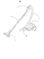
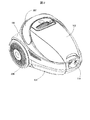
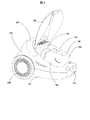
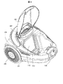
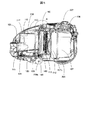
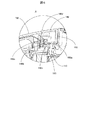
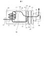
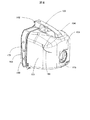
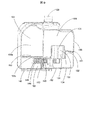
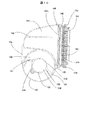
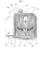
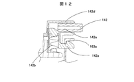
図1は、本発明の一実施の形態を示す電気掃除機の外観斜視図である。図2は、この掃除機本体の斜視図である。図3は、この掃除機本体の上蓋を開いた状態を示す斜視図である。図4は、この掃除機本体の上蓋を開いて、サイクロン分離筒と集塵ケースを取り外した状態を示す斜視図である。図5は、この掃除機本体の断側面図である。図6は、図5のA部拡大図である。図7は、この掃除機本体内の空気の流れを示す模式図である。図8はサイクロン分離筒104と集塵ケース105の外観斜視図である。図9はサイクロン分離筒104と集塵ケース105の縦断面図である。図10はサイクロン分離筒104と集塵ケース105の断面図である。図11はサイクロン分離筒104と集塵ケース105を排気側から見たときの側面図である。図12はボタン部の構成図である。   FIG. 1 is an external perspective view of a vacuum cleaner showing an embodiment of the present invention. FIG. 2 is a perspective view of the cleaner body. FIG. 3 is a perspective view showing a state in which the upper cover of the cleaner body is opened. FIG. 4 is a perspective view showing a state where the upper lid of the cleaner body is opened and the cyclone separating cylinder and the dust collecting case are removed. FIG. 5 is a sectional side view of the cleaner body. FIG. 6 is an enlarged view of part A in FIG. FIG. 7 is a schematic diagram showing the flow of air in the cleaner body. FIG. 8 is an external perspective view of the cyclone separating cylinder 104 and the dust collecting case 105. FIG. 9 is a longitudinal sectional view of the cyclone separating cylinder 104 and the dust collecting case 105. FIG. 10 is a cross-sectional view of the cyclone separating cylinder 104 and the dust collecting case 105. FIG. 11 is a side view of the cyclone separating cylinder 104 and the dust collecting case 105 as viewed from the exhaust side. FIG. 12 is a configuration diagram of the button unit.

この実施の形態における電気掃除機は、図1に示すように、掃除機本体1とホース2と手元操作管3と伸縮継ぎ手管4と吸口5を備え、掃除機本体1と手元操作管3をホース2で接続し、この手元操作管3に伸縮継ぎ手管4を介して吸口5を接続して使用する。   As shown in FIG. 1, the electric vacuum cleaner in this embodiment includes a vacuum cleaner body 1, a hose 2, a hand operation tube 3, an expansion joint tube 4, and a suction port 5, and the vacuum cleaner body 1 and the hand operation tube 3 are connected to each other. A hose 2 is used for connection, and a suction port 5 is connected to the local operation pipe 3 via an expansion joint pipe 4 for use.

掃除機本体1は、電動送風機(後述する)を内蔵し、この電動送風機の吸気力によって吸口5から吸気することによって該吸気流に乗せて塵埃を吸い込み、吸い込んだ含塵空気を伸縮継ぎ手管4と手元操作管3とホース2を介して掃除機本体1に吸い込ませ、サイクロン分離式の集塵部103で塵埃捕捉(集塵)した後に機外に排気する。   The vacuum cleaner body 1 incorporates an electric blower (described later), and sucks in dust from the intake flow by suctioning from the suction port 5 by the suction force of the electric blower. Then, the vacuum cleaner main body 1 is sucked through the hand control pipe 3 and the hose 2, and dust is captured (collected) by the cyclone separation type dust collecting section 103, and then exhausted outside the machine.

掃除機本体1は、図2から図5に示すように、下ケース101と上蓋102の間に、サイクロン分離筒104と一体となった集塵ケース105を着脱可能に縦置き装着し、下ケース101と上ケース150の間にフィルターケース113と、このフィルターケース113に取り付ける補助フィルター112と電動送風機107とコードリール110とを内蔵する。また、下ケース101は、この掃除機本体1を床面に走行させるための走行車輪208と案内車輪208bを備えている。さらに、上ケース150の上部にはハンドル207が転回可能に取り付けられており、掃除機本体1を持ち運ぶ事ができる。   As shown in FIGS. 2 to 5, the vacuum cleaner main body 1 has a dust collection case 105 integrated with a cyclone separation cylinder 104 mounted vertically between the lower case 101 and the upper lid 102 so as to be detachable. A filter case 113, an auxiliary filter 112 attached to the filter case 113, an electric blower 107, and a cord reel 110 are housed between the 101 and the upper case 150. The lower case 101 includes a traveling wheel 208 and a guide wheel 208b for causing the cleaner body 1 to travel on the floor surface. Furthermore, a handle 207 is attached to the upper part of the upper case 150 so as to be able to rotate, and the cleaner body 1 can be carried.

上蓋102は、上ケース150の上側後部に転回可能に取り付けている。この上蓋102を閉じた状態において、サイクロン分離筒104の入口管115とホース接続口部116とが弾性体部材を介して気密状態に当接し、集塵ケース105とフィルター枠140とが気密状態に当接し、フィルター枠140とフィルター枠163とが気密状態に当接し、フィルター枠163と補助フィルター112が収納されるフィルターケース113との間が気密状態に当接している。さらに、このフィルターケース113と、電動送風機107が弾性体の防振ゴムを介して気密状態に当接している。また、サイクロン分離筒104の下部の排気口120と集塵ケース105の下部に設けた連絡通路145とが気密状態に当接している。ここで、サイクロン分離筒104の軸方向は鉛直方向を向いているが、鉛直方向でなく斜め方向に傾いたり、横方向を向いていてもかまわない。   The upper lid 102 is attached to the upper rear portion of the upper case 150 so as to be rotatable. In a state where the upper lid 102 is closed, the inlet pipe 115 and the hose connection port portion 116 of the cyclone separating cylinder 104 are brought into an airtight state through the elastic member, and the dust collecting case 105 and the filter frame 140 are brought into an airtight state. The filter frame 140 and the filter frame 163 are in contact with each other in an airtight state, and the filter case 163 and the filter case 113 in which the auxiliary filter 112 is accommodated are in contact with each other in an airtight state. Further, the filter case 113 and the electric blower 107 are in contact with each other through an elastic vibration-proof rubber in an airtight state. Further, the exhaust port 120 at the lower part of the cyclone separation cylinder 104 and the communication passage 145 provided at the lower part of the dust collecting case 105 are in contact with each other in an airtight state. Here, the axial direction of the cyclone separating cylinder 104 is oriented in the vertical direction, but it may be inclined in the oblique direction instead of the vertical direction or in the lateral direction.

この掃除機本体1は、図6に示すように、ホース2を介して含塵空気を入口管115より、サイクロン分離筒104に流し入れて、下側から上側に旋回させることにより遠心分離作用で塵埃を分離して、上部の連通口117から上部開口118を通して集塵ケース105に塵埃を搬送する。サイクロン分離筒104からの排気の一部は内筒131を通り、サイクロン分離筒104の下部に設けた排気口120から排気される。また、サイクロン分離筒104に流入した空気の一部は、集塵ケース105に流れ込み、第1のフィルター106によって塵埃を捕捉する。集塵ケース105の排気は第1のフィルター106の後方にある集塵ケース排気口144から、第2のフィルター161、補助フィルター112の順に通して電動送風機107に吸込ませる。この時サイクロン分離筒104からの排気は前記排気口120から連絡通路145、サイクロン部流出口146を介して、集塵ケース排気口144からの排気と合せて、第2のフィルター161、および、補助フィルター112を通して電動送風機107に吸込ませる。この電動送風機107からの排気はフィルター108を介して、一部は排気流路(図示せず)を介し、一部はコードリール(図示せず)に流してこれらを冷却し、その後に機外に放出される。   As shown in FIG. 6, the vacuum cleaner main body 1 has a centrifugal separation action by flowing dust-containing air from the inlet pipe 115 into the cyclone separation cylinder 104 through the hose 2 and swirling from the lower side to the upper side. And the dust is conveyed from the upper communication port 117 to the dust collecting case 105 through the upper opening 118. Part of the exhaust from the cyclone separation cylinder 104 passes through the inner cylinder 131 and is exhausted from an exhaust port 120 provided in the lower part of the cyclone separation cylinder 104. Part of the air that has flowed into the cyclone separation cylinder 104 flows into the dust collection case 105, and dust is captured by the first filter 106. The exhaust from the dust collecting case 105 is sucked into the electric blower 107 through the dust collecting case exhaust port 144 located behind the first filter 106 through the second filter 161 and the auxiliary filter 112 in this order. At this time, the exhaust from the cyclone separation cylinder 104 is combined with the exhaust from the dust collecting case exhaust port 144 through the communication passage 145 and the cyclone outlet 146 from the exhaust port 120, the second filter 161, and the auxiliary The electric blower 107 is sucked through the filter 112. Exhaust air from the electric blower 107 is cooled through a filter 108, partly through an exhaust passage (not shown), and partly through a cord reel (not shown). To be released.

つまり、排気口120から流出する空気流の風量Aと、集塵ケース排気口144から流出する空気流の風量Bのサイクロン分離筒104で分流した空気流は、第2のフィルター161の上流側で合流し、この第2のフィルター161に流入する。そして、この空気流は第2のフィルター161で微細塵を集塵された後、電動送風機107に吸引される。   In other words, the airflow A flowing out of the exhaust port 120 and the airflow B flowing out of the dust collecting case exhaust port 144 are separated by the cyclone separation cylinder 104 on the upstream side of the second filter 161. Merge and flow into the second filter 161. This air flow is sucked into the electric blower 107 after fine dust is collected by the second filter 161.

また、上蓋102を透明のプラスチック素材で製作しておけば、図2に示すように上蓋102を閉じた際、この上蓋102がサイクロン分離筒104や、集塵ケース105を覆う場合でも、塵埃のたまり具合は目視で確認することができる。   Further, if the upper lid 102 is made of a transparent plastic material, even when the upper lid 102 covers the cyclone separating cylinder 104 or the dust collecting case 105 when the upper lid 102 is closed as shown in FIG. The state of accumulation can be confirmed visually.

ここで、前記サイクロン分離筒104で遠心分離された塵埃が連通口117を通じてサイクロン分離筒104から流出する方向は、サイクロン分離筒104内での旋回方向で、かつ、サイクロン分離筒104の接線方向である。このため、本実施の形態では、サイクロン分離筒104の連通口117と、この連通口117と連通する集塵ケース105の上部開口118の両者を、前記集塵ケース105内の開閉する第1のフィルター106から最も離れた電気掃除機本体1の前面側(ホース接続口部116側)に配置することができる。ここで、サイクロン分離筒104で遠心分離された塵埃は、開閉する第1のフィルター106付近から堆積し、サイクロン分離筒104の連通口117と、この連通口117と連通する集塵ケース105の上部開口118側へと、順に堆積していくので、前記集塵ケース105に塵埃が充填されるまで、塵埃が前記連通口117と前記上部開口118を塞ぎにくい。つまり、前記集塵ケース105の容積を有効利用することができる。   Here, the direction in which the dust centrifuged in the cyclone separation cylinder 104 flows out of the cyclone separation cylinder 104 through the communication port 117 is a turning direction in the cyclone separation cylinder 104 and a tangential direction of the cyclone separation cylinder 104. is there. For this reason, in the present embodiment, both the communication port 117 of the cyclone separation cylinder 104 and the upper opening 118 of the dust collection case 105 communicating with the communication port 117 are opened and closed in the dust collection case 105. It can arrange | position in the front side (hose connection port part 116 side) of the vacuum cleaner main body 1 furthest from the filter 106. Here, the dust centrifuged in the cyclone separation cylinder 104 is accumulated from the vicinity of the first filter 106 that opens and closes, and the communication port 117 of the cyclone separation cylinder 104 and the upper part of the dust collecting case 105 that communicates with the communication port 117. Since the particles sequentially accumulate on the opening 118 side, it is difficult for the dust to block the communication port 117 and the upper opening 118 until the dust collecting case 105 is filled with dust. That is, the volume of the dust collecting case 105 can be effectively used.

ここで、サイクロン分離筒104と集塵ケース105の詳細について説明する。まず、塵埃の流れについて述べる。塵埃を含んだ空気は、サイクロン分離筒104の連通口117から集塵ケース105の上部に設けられた上部開口118より集塵ケース105に流入する。ここで、網フィルター106aで空気中の比較的大きな塵埃がせき止められ、網フィルター106aの手前から堆積していく。細かい塵埃は、第1のフィルター106で捕捉され、さらに細かい塵埃は第2のフィルター161で集塵される。第2のフィルター161を通過した塵埃は補助フィルター112に流れていく。   Here, details of the cyclone separating cylinder 104 and the dust collecting case 105 will be described. First, the flow of dust will be described. The dust-containing air flows into the dust collection case 105 from the communication port 117 of the cyclone separation cylinder 104 through the upper opening 118 provided in the upper part of the dust collection case 105. Here, a relatively large amount of dust in the air is dammed up by the mesh filter 106a and accumulates from before the mesh filter 106a. Fine dust is captured by the first filter 106, and finer dust is collected by the second filter 161. Dust that has passed through the second filter 161 flows to the auxiliary filter 112.

また、網フィルター133は、内筒131から流出する空気流にのった繊維塵や、紙などの塵埃が吹き抜けるのを防止するように機能する。この網フィルター133を通過したさらに細かい塵埃は、上記と同様に、第2のフィルター161で集塵され、第2のフィルター161を通過した塵埃は補助フィルター112に流れていく。   Further, the net filter 133 functions so as to prevent fiber dust or paper dust on the airflow flowing out from the inner cylinder 131 from blowing through. Finer dust that has passed through the mesh filter 133 is collected by the second filter 161 as described above, and the dust that has passed through the second filter 161 flows to the auxiliary filter 112.

サイクロン分離筒104の外筒135には、空気取り入れ口である入口管115が、このサイクロン分離筒104の中心軸方向長さの中央より下部に設けられ、略円筒形をなすサイクロン分離筒104の略接線方向に空気が入るように設置されている。サイクロン分離筒104の中央より上部に連通口117が設けられ、集塵ケース105に塵埃とともに空気を流入させる。サイクロン分離筒104の下部には内筒131が設けられ、下部の排気口120につながっている。ここで、内筒131にネジなどで内筒キャップ152を取り付け、排気口120と連絡通路145間は弾性シール部材153を介し、外筒135と内筒131は弾性シール部材151を介して取り付ければ気密を取り易い。内筒131は筒部134と、この筒部134に螺旋状に巻き付いた隔壁132と、入口管115と前記筒部134を結ぶ案内壁137と、前記隔壁132の外周側に配置した外壁139で構成され、該隔壁132の最も高い部分の高さと、前記筒部134の高さを略等しくしている。ここでは、案内壁137の高さも前記筒部134の高さと略等しくしている。また、筒部134には網フィルター133として樹脂繊維性の網を筒部134と一体にインサート成形により構成している。網フィルター133は図8に示すように、筒部134の側面の円筒部分に構成してもよく、筒部134の側面の円筒部分と案内壁132とに構成してもかまわない。   In the outer cylinder 135 of the cyclone separation cylinder 104, an inlet pipe 115 as an air intake is provided below the center of the length in the central axis direction of the cyclone separation cylinder 104, and the cyclone separation cylinder 104 having a substantially cylindrical shape is provided. It is installed so that air can enter in the direction of tangential line. A communication port 117 is provided above the center of the cyclone separation cylinder 104 to allow air to flow into the dust collecting case 105 together with dust. An inner cylinder 131 is provided at the lower part of the cyclone separation cylinder 104 and is connected to the lower exhaust port 120. Here, if the inner cylinder cap 152 is attached to the inner cylinder 131 with a screw or the like, an elastic seal member 153 is attached between the exhaust port 120 and the communication passage 145, and the outer cylinder 135 and the inner cylinder 131 are attached via the elastic seal member 151. Easy to be airtight. The inner cylinder 131 includes a cylinder part 134, a partition wall 132 spirally wound around the cylinder part 134, a guide wall 137 connecting the inlet pipe 115 and the cylinder part 134, and an outer wall 139 disposed on the outer peripheral side of the partition wall 132. The height of the highest part of the partition wall 132 is substantially equal to the height of the cylindrical part 134. Here, the height of the guide wall 137 is also substantially equal to the height of the cylindrical portion 134. In addition, a resin fiber net is formed as a net filter 133 in the cylinder part 134 by integral molding with the cylinder part 134. As shown in FIG. 8, the mesh filter 133 may be configured as a cylindrical portion on the side surface of the cylindrical portion 134, or may be configured as a cylindrical portion on the side surface of the cylindrical portion 134 and the guide wall 132.

ここで、前記内筒131の筒部134は、前記隔壁132の最も高い部分の高さと略等しく構成しているので、サイクロン分離筒104から空気を排出する内筒131の筒部134に毛髪や、犬や猫などのペットの毛、糸くずなどが巻き付くことを防ぐことができる。また、毛髪などの塵埃が内筒の131の筒部134に巻き付こうとしても、この筒部134に一周巻きつくことができず、これらの塵埃はサイクロン分離筒104内を上昇する旋回空気流により、上方へ移動し、集塵ケース105へと搬送される。このため、内筒134の排気口面積の減少を防げるので、掃除機の吸込み力が低下しにくい。さらに、毛髪などの長い塵埃がサイクロン分離筒104内にとどまらず、集塵室に搬送されることで、このサイクロン分離筒104内の気流の乱れを抑制できるので、掃除機の吸込み力が低下しにくくできる。   Here, since the cylindrical portion 134 of the inner cylinder 131 is configured to be substantially equal to the height of the highest portion of the partition wall 132, hair and hair are added to the cylindrical portion 134 of the inner cylinder 131 that discharges air from the cyclone separating cylinder 104. It can prevent the hair of pets, such as dogs and cats, and lint from wrapping around. Further, even if dust such as hair tries to wrap around the cylindrical portion 134 of the inner cylinder 131, it cannot wrap around the cylindrical portion 134, and these dusts are swirling airflows that rise in the cyclone separating cylinder 104. Therefore, it moves upward and is conveyed to the dust collection case 105. For this reason, since the reduction | decrease of the exhaust-port area of the inner cylinder 134 can be prevented, the suction force of a cleaner is hard to fall. Further, since long dust such as hair does not stay in the cyclone separating cylinder 104 but is conveyed to the dust collecting chamber, the turbulence of the air current in the cyclone separating cylinder 104 can be suppressed, so the suction force of the vacuum cleaner is reduced. It can be difficult.

さらに、内筒131の筒部134に毛髪や、犬や猫などのペットの毛、糸くずなどが巻き付くことを防ぐことにより、メンテナンス性能を向上したサイクロン分離式の集塵部103を実現できる。なお、内筒131の構成を以上のようにすれば、サイクロン分離筒104の上から下に含塵空気を流入させた場合や、サイクロン分離筒104を横置きにし、旋回流の中心軸が略水平方向に配置した場合でも同様の効果が選られる。   Furthermore, by preventing hair, pet hair such as dogs and cats, lint, etc. from wrapping around the tube part 134 of the inner cylinder 131, a cyclone separation type dust collecting part 103 with improved maintenance performance can be realized. . If the configuration of the inner cylinder 131 is as described above, when the dust-containing air is introduced from the top to the bottom of the cyclone separation cylinder 104, or the cyclone separation cylinder 104 is placed horizontally, the central axis of the swirling flow is substantially The same effect can be selected even when arranged horizontally.

ここで、サイクロン分離筒104の内部や、内筒131の網フィルターが汚れた場合は、上蓋102を上に開け、この状態で集塵ケース105の上部の取っ手123を持って、サイクロン分離筒104と集塵ケース105を取出す。この際、使用者が、取っ手123を保持した際に、この取っ手123を保持した使用者の指がボタン142の付近にあるが、この使用者の指は上ケース150や、前記上蓋102が邪魔になり、ボタン142を押すことができない。なお、本実施の形態では、前記上蓋102を上に開けた時に、上ケ−ス150とボタン142の隙間は5mmとしているが、子供が扱うことを考えるとこの隙間は6mm以下にするのが好ましい。このため、前記使用者は、掃除機本体1から集塵部103を構成する前記サイクロン分離筒104と全前記集塵ケース105を取出す際に、誤ってボタン142を押して、集塵ケース105から塵埃を廃棄するための蓋体であるフィルター枠140とフィルター枠163の両者を一緒に開いて、ゴミをまき散らす恐れはない。このため、電動送風機107が、この誤ってまき散らしたゴミを吸引することを防げるので故障を予防できる。   Here, when the inside of the cyclone separation cylinder 104 or the net filter of the inner cylinder 131 becomes dirty, the upper lid 102 is opened upward, and in this state, the handle 123 at the upper part of the dust collecting case 105 is held to hold the cyclone separation cylinder 104. Then, the dust collecting case 105 is taken out. At this time, when the user holds the handle 123, the finger of the user holding the handle 123 is in the vicinity of the button 142, and the user's finger is blocked by the upper case 150 and the upper lid 102. The button 142 cannot be pressed. In the present embodiment, when the upper lid 102 is opened upward, the gap between the upper case 150 and the button 142 is 5 mm. However, in consideration of handling by children, this gap should be 6 mm or less. preferable. For this reason, when the user takes out the cyclone separating cylinder 104 and the entire dust collecting case 105 constituting the dust collecting unit 103 from the vacuum cleaner body 1, the user erroneously presses the button 142 to remove dust from the dust collecting case 105. The filter frame 140 and the filter frame 163, which are lids for disposing of waste, are opened together, and there is no risk of dust being scattered. For this reason, the electric blower 107 can be prevented from sucking the dust scattered by mistake, so that a failure can be prevented.

さらに、掃除機本体1から前記サイクロン分離筒104と全前記集塵ケース105を取出す際に、誤ってボタン142を押さないようにボタン142にカバーなどを設ける必要がないので部品点数を少なくすることができる。   Furthermore, when removing the cyclone separating cylinder 104 and all the dust collecting cases 105 from the vacuum cleaner main body 1, it is not necessary to provide a cover or the like on the button 142 so that the button 142 is not accidentally pressed. Can do.

また、前記サイクロン分離筒104と前記集塵ケース105を前記掃除機本体1から取出す方向は垂直方向で、ボタン142を押す方向は水平方向と異なった方向に動くように配置している。このため、使用者は同時に2方向に動く動作を行い難いので、前記サイクロン分離筒104と全前記集塵ケース105を前記掃除機本体1から取出す際に、誤ってボタン142を押して、集塵ケース105からフィルター枠140とフィルター枠163の両者を一緒に開いて、ゴミをまき散らしにくい。また、ゴミ捨て時には、ボタン142を押す動作をすれば、集塵ケース105からフィルター枠140とフィルター枠163の両者が一緒に開くので、使用者は手間がかからずに、ゴミ捨てすることが可能である。   The cyclone separating cylinder 104 and the dust collecting case 105 are arranged so that the direction in which the cyclone separating cylinder 104 and the dust collecting case 105 are taken out from the cleaner body 1 is vertical, and the direction in which the button 142 is pressed moves in a direction different from the horizontal direction. For this reason, since it is difficult for the user to move in two directions at the same time, when the cyclone separating cylinder 104 and the entire dust collecting case 105 are taken out from the cleaner body 1, the user presses the button 142 by mistake, The filter frame 140 and the filter frame 163 are both opened from 105 so that dust is not easily scattered. Further, when the user discards the dust, if the user presses the button 142, both the filter frame 140 and the filter frame 163 are opened together from the dust collecting case 105. Therefore, the user can discard the dust without much trouble. Is possible.

また、取っ手123と、集塵ケース105から塵埃を廃棄するための蓋体であるフィルター枠140とフィルター枠163の両者を開放するボタンを近接して設けているので、使用者がゴミ捨て時にこの蓋体を開放するのに、保持部である取っ手123を持ち替えたり、ゴミを廃棄する際に両手で集塵部103を持つ必要がなく、簡便にゴミを廃棄する事ができる。   Further, since the handle 123 and a button for opening both the filter frame 140 and the filter frame 163 which are lids for discarding dust from the dust collecting case 105 are provided close to each other, the user can dispose of this when the garbage is thrown away. To open the lid, it is not necessary to change the handle 123 as a holding part or to have the dust collecting part 103 with both hands when discarding the garbage, and the garbage can be easily discarded.

また、前記使用者は、集塵ケース105から塵埃を廃棄する際に、一方の手で集塵部103の取っ手123を持ち、この集塵部103を袋に入れて、集塵部103の取っ手123を持った手でボタン142を押すことができるので、この袋の中で前記集塵ケース105からゴミを廃棄することができるので、ゴミの廃棄を簡便に行うことができる。   Further, when the user disposes dust from the dust collection case 105, the user holds the handle 123 of the dust collection unit 103 with one hand, puts the dust collection unit 103 in a bag, and handles the dust collection unit 103. Since the button 142 can be pushed with the hand holding the 123, the garbage can be discarded from the dust collecting case 105 in the bag, so that the garbage can be easily discarded.

ここで、前記使用者は、掃除機本体1から前記サイクロン分離筒104と全前記集塵ケース105を取出した後、前記ボタン142を押して、集塵ケース105からフィルター枠140とフィルター枠163の両者を一緒に開いて、集塵ケース105内の塵埃とポケット162内の塵埃を廃棄する。次に、サイクロン分離筒104から内筒キャップ152と一体になった内筒131を取り外し、清掃用ブラシを用いて清掃することができる。   Here, after the user removes the cyclone separating cylinder 104 and the entire dust collecting case 105 from the vacuum cleaner body 1, the user presses the button 142 to remove both the filter frame 140 and the filter frame 163 from the dust collecting case 105. Are opened together, and the dust in the dust collecting case 105 and the dust in the pocket 162 are discarded. Next, the inner cylinder 131 integrated with the inner cylinder cap 152 can be removed from the cyclone separation cylinder 104 and cleaned using a cleaning brush.

また、網フィルター133にはゴミの色とは違った色、例えば、黄色に着色することにより、使用者は網フィルター133に塵埃が付着したことを目で確認できるので、網フィルター133に繊維塵とか粉塵などが付いて目詰まりしたことを早く見つけることができ、清掃を早期に行うことができる。   In addition, the mesh filter 133 is colored in a color different from the color of dust, for example, yellow, so that the user can visually confirm that dust has adhered to the mesh filter 133. It is possible to quickly find that it is clogged with dust or the like, and cleaning can be performed early.

ここで、サイクロン分離筒104の内部に設けた内筒131の筒部134に、該内筒131の根元側から先端側へ螺旋状の隔壁132を設け、該隔壁132に略沿って外筒135と内筒131とを弾性シール部材151を介して気密を保つ構成としている。ここで、図9に示すように、外筒135と内筒131の気密は、図の上下方向に付勢することにより気密を保ちやすい。なお、案内壁137の上部付近と当接する部分では外筒135の一部が凹部となるが、この凹部の角部付近をR状にすれば外筒135の強度を確保できる。
なお、シール部材151とシール部材153は一体で構成することもでき、一体で構成した場合は成形を一度で行え、組立ての手間も省略できる。
Here, a spiral partition wall 132 is provided from the root side to the distal end side of the inner cylinder 131 in the cylinder portion 134 of the inner cylinder 131 provided inside the cyclone separation cylinder 104, and the outer cylinder 135 is substantially along the partition wall 132. The inner cylinder 131 is configured to be kept airtight via an elastic seal member 151. Here, as shown in FIG. 9, the airtightness of the outer cylinder 135 and the inner cylinder 131 is easily maintained by urging in the vertical direction in the figure. Note that a portion of the outer cylinder 135 becomes a concave portion in the portion that contacts the vicinity of the upper portion of the guide wall 137, but the strength of the outer cylinder 135 can be ensured by making the vicinity of the corner of the concave portion into an R shape.
Note that the seal member 151 and the seal member 153 can be integrally formed, and when formed integrally, the molding can be performed at one time, and the assembling work can be omitted.

なお、案内壁137の高さは、入口管115の高さよりも高くすれば、入口管115から流入した空気流れと、サイクロン分離筒104内を旋回した空気流れが、干渉や、混合しにくく、これらに付随する乱れを防ぐとともに、流入時の急拡大も防げ、損失を低減することができる。   If the height of the guide wall 137 is higher than the height of the inlet pipe 115, the air flow flowing in from the inlet pipe 115 and the air flow swirling in the cyclone separation cylinder 104 are less likely to interfere and mix, In addition to preventing the turbulence associated with these, it is also possible to prevent sudden expansion during inflow and reduce loss.

集塵ケース105には、サイクロン分離筒104の連通口117に連通する上部開口118が設けられている。集塵ケース105の排気側には、フィルター枠140に取り付けられた第1のフィルター106が設けられている。フィルター枠140は下部に設けた開閉軸143を中心として回動するように設けられ、フィルター枠140が閉まったときには、集塵ケース105とフィルター枠140は気密状態を保って当接している。   The dust collection case 105 is provided with an upper opening 118 that communicates with the communication port 117 of the cyclone separation cylinder 104. A first filter 106 attached to the filter frame 140 is provided on the exhaust side of the dust collection case 105. The filter frame 140 is provided so as to rotate about an opening / closing shaft 143 provided in the lower portion. When the filter frame 140 is closed, the dust collection case 105 and the filter frame 140 are in contact with each other while maintaining an airtight state.

第1のフィルター106の集塵性能は、フィルター材の能力で決定されるが、μmオーダーの塵埃までを分離できる能力を持たせると良い。ここで、第1のフィルター106は発泡性の洗える素材のプラスチックでできたスポンジ、あるいは、水洗いできる不織布、あるいは、水洗できる濾紙材などを用いるのが望ましい。また、発泡性のプラスチック材を用いると、塵埃中に含まれる細かい繊維塵などの通過を防止できるので、第2のフィルター161で取り除きにくい繊維塵が第2のフィルター161側に流入するのを防げるのでなお良い。   The dust collection performance of the first filter 106 is determined by the ability of the filter material, but it is preferable to have the ability to separate up to μm order dust. Here, it is desirable to use a sponge made of foamable and washable plastic, a non-woven fabric that can be washed with water, or a filter paper material that can be washed with water for the first filter 106. In addition, when a foamable plastic material is used, the passage of fine fiber dust contained in the dust can be prevented, so that the fiber dust that is difficult to remove by the second filter 161 can be prevented from flowing into the second filter 161 side. So even better.

また、フィルター枠140には、網フィルター106aがインサート成形等で一体に設けられている。網フィルター106aの集塵性能は、網の目の細かさで決定されるが、集塵性能を高くしすぎると目詰まりも早くなり易いので、全体の集塵能力との兼ね合いで決定するのが望ましい。この網フィルター106aに帯電防止処理を施すと、該網フィルター106aに付着した塵埃が離れやすく、清掃用ブラシを用いて清掃すれば良く、清掃は容易である。さらに、該網フィルター106aに撥水処理などを施すと、水洗いした時の乾燥時間が短くてすむ。   Further, the filter frame 140 is integrally provided with a mesh filter 106a by insert molding or the like. The dust collection performance of the mesh filter 106a is determined by the fineness of the mesh, but if the dust collection performance is too high, clogging is likely to occur quickly, so it is determined in consideration of the overall dust collection capability. desirable. When the net filter 106a is subjected to an antistatic treatment, dust attached to the net filter 106a is easily separated and may be cleaned using a cleaning brush, and cleaning is easy. Furthermore, if the mesh filter 106a is subjected to water repellent treatment, the drying time when washed with water can be shortened.

第1のフィルター106の下流側には、フィルター枠163が設けられ、フィルター枠140とフィルター枠163が閉まったときには、この両者は気密状態を保って当接している。フィルター枠163はフィルター枠140の下部に設けた開閉軸143中心として、フィルター枠140と同軸で回動するように設けられている。ここで、係止部142aは、バネ142bにより該係止部142aと係合部163aが係止するように付勢されているので、フィルター枠140とフィルター枠163は集塵ケース105側に気密状態を保つように係止している。なお、係止部142aと係合部163aの形状は、鉤とするとなおよい。   A filter frame 163 is provided on the downstream side of the first filter 106. When the filter frame 140 and the filter frame 163 are closed, the two are in contact with each other while maintaining an airtight state. The filter frame 163 is provided so as to rotate coaxially with the filter frame 140 about the opening / closing shaft 143 provided at the lower part of the filter frame 140. Here, since the engaging portion 142a is biased by the spring 142b so that the engaging portion 142a and the engaging portion 163a are engaged, the filter frame 140 and the filter frame 163 are airtight on the dust collecting case 105 side. Locks to keep the state. Note that the shapes of the locking portion 142a and the engaging portion 163a are preferably ridges.

フィルター枠163の上方には、取っ手102付近にボタン142が設けられ、このボタン142を押すことにより、係止部142aが押され、この係止部142aと、フィルター枠163に設けている係合部163aとが開放され、フィルター枠140とフィルター枠163が開放されて、ゴミ捨てが可能となる。ここでは、集塵部103を構成するサイクロン分離筒104と集塵ケース105を掃除機本体1に装着したときに、上ケース150や、上蓋102が邪魔となってボタン142を押せないようにするため、該ボタン142は水平方向に動くように設けている。また、図6に示すように、ボタン142と係止部142aの当接面は45度程度に斜めに配置しているので、ボタン142が水平方向に移動した際、このボタン142に押されて係止部142aは垂直方向に動く様に動作する。なお、ボタン142と係止部142aはガイド142cにより、これらの当接面ががたついて動作不良を起こすのを防いでいる。さらに、ボタン142はボタンケース142dにより、移動方向をガイドされるとともに、リブなどにより、ボタンケース142dから脱落するのを防止している。さらに、係止部142aもボタンケース142dにより移動方向をガイドされている。   Above the filter frame 163, a button 142 is provided near the handle 102, and when the button 142 is pressed, the locking portion 142 a is pressed, and the locking portion 142 a and the engagement provided on the filter frame 163 are provided. The part 163a is opened, and the filter frame 140 and the filter frame 163 are opened, so that dust can be discarded. Here, when the cyclone separation cylinder 104 and the dust collection case 105 constituting the dust collection unit 103 are attached to the cleaner body 1, the upper case 150 and the upper lid 102 are obstructed so that the button 142 cannot be pressed. Therefore, the button 142 is provided to move in the horizontal direction. Further, as shown in FIG. 6, since the contact surface of the button 142 and the locking portion 142a is disposed obliquely at about 45 degrees, when the button 142 moves in the horizontal direction, it is pushed by the button 142. The locking portion 142a operates to move in the vertical direction. It should be noted that the button 142 and the locking portion 142a are prevented by the guide 142c from rattling their contact surfaces and causing malfunctions. Further, the button 142 is guided in the moving direction by the button case 142d, and is prevented from falling off the button case 142d by a rib or the like. Further, the locking portion 142a is also guided in the moving direction by the button case 142d.

ここで、図12に示すように、ボタン142に水平方向のガイド142eを設けて、ボタン142の移動方向をガイドさせるとともに、このガイド142eによって、ボタン142がボタンケース142dから脱落するのを防ぐのを兼用することも可能である。   Here, as shown in FIG. 12, the button 142 is provided with a horizontal guide 142e to guide the moving direction of the button 142, and this guide 142e prevents the button 142 from falling off the button case 142d. It is also possible to use both.

また、係止部142aの移動はボタン142による摩擦力を利用しているので、これらの部材には摩擦摩耗特性に優れ、長時間の摺動特性に優れたポリオキシメチレン(POM)を用いるのが好ましい。   Further, since the movement of the locking portion 142a uses the frictional force generated by the button 142, these members are made of polyoxymethylene (POM), which has excellent frictional wear characteristics and long-time sliding characteristics. Is preferred.

なお、本実施の形態例では、開閉軸143が下にあり、フィルター枠140とフィルター枠163が、図中上部から開くことになるので、集塵ケース105を横に向けて塵埃を捨てるのが良い。   In the present embodiment, the opening / closing shaft 143 is at the bottom, and the filter frame 140 and the filter frame 163 are opened from the upper part in the figure, so that the dust collection case 105 is directed sideways and the dust is discarded. good.

また、本実施の形態では、集塵部103はサイクロン分離式で構成し、サイクロン分離筒104と、集塵ケース105と、フィルター類などで構成したものを示したが、集塵部を集塵ケースと、フィルターと、開閉する蓋と、この蓋を開閉するためのボタンを有するものとで構成した集塵部にサイクロン分離筒を持たない形式のものでも、同様の構成が可能である。   Further, in the present embodiment, the dust collection unit 103 is configured by a cyclone separation type and is configured by a cyclone separation cylinder 104, a dust collection case 105, filters, and the like. A similar configuration is possible even in a type that does not have a cyclone separating cylinder in a dust collecting portion that is configured by a case, a filter, a lid that opens and closes, and a button that opens and closes the lid.

フィルター枠163には第2のフィルター161が一体に成形されている。第2のフィルター161は、フィルター材をひだ折りに形成し、山折りの折り線方向は床面に略垂直方向としている。この第2のフィルター161には洗える不織布、洗えるろ紙材などを用いる。さらに、撥水処理を施すと水洗い時の乾燥時間を短くできるので、なお良い。また、第2のフィルター161には下流側の山の頂部にプラスチック製の補強部166が第2のフィルター161と一体に形成されている。なお、補強部166は山部全てに渡って設けているのではなく、除塵装置164の除塵ばね170が当たる部分の近くのみに設けている。これにより、除塵ばね170が与えた第2のフィルター161への振動が第2のフィルター161全体に伝わり易くなるので第2のフィルター161を除塵する能力を高くできる。また、補強部166を山部の一つの端まで、例えば、本実施の形態例では、下側の端まで伸ばせば、多少除塵能力が低下するがかまわない。また、第2のフィルター161下流側の山の頂部にプラスチック製の補強部166を設けているので、フィルターの有効面積の低下を抑えることができ、通気抵抗の増大を防止できる。   A second filter 161 is formed integrally with the filter frame 163. The second filter 161 is formed by fold-folding the filter material, and the fold line direction of the mountain fold is substantially perpendicular to the floor surface. The second filter 161 is made of washable nonwoven fabric, washable filter paper material, or the like. Furthermore, if water-repellent treatment is performed, the drying time at the time of washing with water can be shortened. Further, the second filter 161 is integrally formed with the second filter 161 at the top of the mountain on the downstream side. In addition, the reinforcement part 166 is not provided over all mountain parts, but is provided only in the vicinity of the part which the dust removal spring 170 of the dust removal apparatus 164 contacts. Thereby, since the vibration to the second filter 161 given by the dust removal spring 170 is easily transmitted to the entire second filter 161, the ability to remove dust from the second filter 161 can be increased. Further, if the reinforcing portion 166 is extended to one end of the peak portion, for example, in the present embodiment, the dust removal capability may be slightly reduced. Moreover, since the plastic reinforcement part 166 is provided in the peak part of the 2nd downstream of the filter 161, the fall of the effective area of a filter can be suppressed and increase of ventilation resistance can be prevented.

さらに、第2のフィルター161を清掃するときに清掃用ブラシ168を用いて第2のフィルター161をこすった場合、補強部166があるので、前記第2のフィルター161のフィルター材が図中左右方向に逃げないので、第2のフィルター161を除塵する能力を高めることができる。なお、第2のフィルター161に帯電防止処理を施すと、第2のフィルター161を除塵時に塵埃が剥離し易く、第2のフィルター161を除塵する能力を高めることができる。   Further, when the second filter 161 is rubbed with the cleaning brush 168 when the second filter 161 is cleaned, there is a reinforcing portion 166, so that the filter material of the second filter 161 is the horizontal direction in the figure. Therefore, the ability to remove dust from the second filter 161 can be enhanced. Note that when the second filter 161 is subjected to an antistatic treatment, dust is easily separated when the second filter 161 is dust-removed, and the ability to remove the second filter 161 can be enhanced.

第1のフィルター106は、フィルター枠140と第2のフィルター161とで挟み込まれ、なおかつ、フィルター枠140に設けたリブで固定されて設置されている。第1のフィルター106に塵埃が溜まってくると抵抗が増加し、第1のフィルター106は下流側へと力を受けるが、第2のフィルター161の山部で押さえられているので、流れ方向に局部的に圧縮されることもなく、第1のフィルター106の変形を防ぐことができる。このため、第1のフィルター106の目がつぶれることによる流れ抵抗の増加を抑制でき、吸込み力を維持しやすい。   The first filter 106 is sandwiched between the filter frame 140 and the second filter 161 and is fixed by a rib provided on the filter frame 140. When dust accumulates in the first filter 106, the resistance increases, and the first filter 106 receives a force toward the downstream side, but is pressed by the peak portion of the second filter 161, and thus in the flow direction. The first filter 106 can be prevented from being deformed without being compressed locally. For this reason, it is possible to suppress an increase in flow resistance due to the crushing of the first filter 106 and to easily maintain the suction force.

また、第2のフィルター161には、内筒131を通じてサイクロン分離筒104の排気口120から流出した空気と、集塵ケース105の排気口144を流出した空気が合流して通過するようにしているので、この第2のフィルター161を各流路に区切る必要はない。つまり、この第2のフィルター161は、一つの除塵部で除塵を行う事ができる。   In addition, the air that flows out from the exhaust port 120 of the cyclone separation cylinder 104 and the air that flows out of the exhaust port 144 of the dust collecting case 105 merge and pass through the second filter 161 through the inner cylinder 131. Therefore, it is not necessary to divide the second filter 161 into each flow path. That is, the second filter 161 can perform dust removal with one dust removing unit.

また、第2のフィルター161には、内筒131及び排気口120から流出した空気と、集塵ケース排気口144を流出した空気が合流して通過するようにしている。これにより、各流路毎に区画したフィルターを設けるよりも、1つの第2のフィルター161を用いる方が流路面積を大きくする事ができ、フィルターの目詰まりを遅らせる事ができる。さらに、集塵ケース105に吸引したゴミの量によって、排気口120から流出した空気の風量と、集塵ケース排気口144を流出した空気の風量の比は変化していく。第2のフィルター161は、フィルター材をひだ折りに形成し、山折りの折り線方向は床面に略垂直方向としているので、サイクロン部流出口144を流出した空気は、第2のフィルター161の山と山の間を通過しながらこの第2のフィルター161を通過する事ができる。さらに、これらの各風量が合流して混合してから1つの第2のフィルター161を通過するので、フィルターを通過する空気の流速は過大にならず、通気抵抗の増大や、フィルターの集塵率の低下を防げる。   In addition, the air that flows out from the inner cylinder 131 and the exhaust port 120 and the air that flows out from the dust collection case exhaust port 144 merge and pass through the second filter 161. As a result, the flow path area can be increased and the clogging of the filter can be delayed by using one second filter 161 rather than providing a filter partitioned for each flow path. Furthermore, the ratio of the amount of air flowing out of the exhaust port 120 and the amount of air flowing out of the dust collecting case exhaust port 144 changes depending on the amount of dust sucked into the dust collecting case 105. The second filter 161 is formed by folding the filter material, and the fold line direction of the mountain fold is substantially perpendicular to the floor surface. Therefore, the air flowing out of the cyclone outlet 144 is The second filter 161 can be passed while passing between the mountains. Furthermore, since these airflows merge and mix and pass through one second filter 161, the flow rate of air passing through the filter does not become excessive, increasing the airflow resistance, and the dust collection rate of the filter. Can be prevented.

また、フィルター枠163には、両端部をネジ2個所で設置された円弧状のガイド165を設けている。ここで、除塵装置164は、フィルター枠163の上部にある支点167に回動可能にネジ止めされ、下端部がガイド165に挟み込まれている。使用者は除塵装置164のほぼ中央部にある手持ち部を持ち、図14の左右方向に除塵装置164を動かすことによって、第2のフィルター161を除塵することができる。   In addition, the filter frame 163 is provided with arc-shaped guides 165 having both ends installed with two screws. Here, the dust removing device 164 is rotatably screwed to a fulcrum 167 at the upper portion of the filter frame 163, and the lower end portion is sandwiched between the guides 165. The user can remove the second filter 161 by moving the dust removing device 164 in the left-right direction in FIG.

第1のフィルター106の清掃は、フィルター枠140とフィルター枠163を開けて、フィルター枠140から第1のフィルター106を取り出して洗うなどして行うことができる。また、網フィルター106aに付着したゴミは、清掃用ブラシで網フィルター106aの表面をこすることや、水洗いすることにより清掃できる。第2のフィルター161の清掃は、フィルター枠140とフィルター枠163を開けた状態にして、集塵ケース105を含めて、清掃用ブラシを使って第2のフィルター161の表面をこすることや水洗いすることにより行えばよい。   The cleaning of the first filter 106 can be performed by opening the filter frame 140 and the filter frame 163, removing the first filter 106 from the filter frame 140, and washing. Further, dust adhering to the mesh filter 106a can be cleaned by rubbing the surface of the mesh filter 106a with a cleaning brush or washing with water. The second filter 161 is cleaned by rubbing the surface of the second filter 161 using a cleaning brush, including the dust collecting case 105, with the filter frame 140 and the filter frame 163 opened, and washing with water. To do so.

なお、フィルター枠140とフィルター枠163とが同じ開閉軸143を中心として回動でき、かつ、それぞれを個別に外すことができなくすれば、フィルター枠140とフィルター枠163とを付け忘れて運転するのを防げる。   If the filter frame 140 and the filter frame 163 can rotate about the same opening / closing shaft 143 and cannot be removed individually, the filter frame 140 and the filter frame 163 are forgotten to be operated. Can be prevented.

集塵ケース105は、壁105bにより塵埃収納部105aと連絡通路145に分けられ、この連絡通路145の下部にはポケット162を設けている。フィルター枠140は、塵埃収容部105aに面する部分に網フィルター106aを設け、壁105bと接合する部分は弾性シール部材により気密を保って当接するようになっており、塵埃収容部105aからサイクロン流出口146へゴミが流出するのを防いでいる。また、サイクロン分離筒104の排気口120と連絡通路145も弾性シール部材153を介し気密を保って当接している。   The dust collection case 105 is divided into a dust storage part 105a and a communication passage 145 by a wall 105b, and a pocket 162 is provided below the communication passage 145. The filter frame 140 is provided with a mesh filter 106a in a part facing the dust container 105a, and a part joined to the wall 105b is in contact with the elastic seal member while maintaining airtightness, and the cyclone flow from the dust container 105a. Garbage is prevented from flowing out to the outlet 146. Further, the exhaust port 120 of the cyclone separating cylinder 104 and the communication passage 145 are also in contact with each other through an elastic seal member 153 while maintaining airtightness.

フィルター枠163の外周側には、フィルター枠163と一体となった弾性シール部172があり、電動送風機107の前に設けられた補助フィルター112を収納するフィルターケース113と気密を保って当接している。なお、集塵ケース105を掃除機本体1に収納したときに、弾性シール部172は垂直方向ではなく、上側が電動送風機107側に傾斜して設けている。このため、集塵ケース105を掃除機本体1に押し込むことで、気密が取れ易くなるとともに、掃除機本体1から集塵ケース105の着脱をし易くする。さらに、フィルター枠163の弾性シール部172はフィルター枠140とも気密も取れるので、シール部材の数を低減できるという効果も有る。   On the outer peripheral side of the filter frame 163, there is an elastic seal portion 172 that is integrated with the filter frame 163, and is in contact with the filter case 113 that houses the auxiliary filter 112 provided in front of the electric blower 107 while maintaining airtightness. Yes. When the dust collection case 105 is stored in the cleaner body 1, the elastic seal portion 172 is provided not on the vertical direction but on the upper side inclined to the electric blower 107 side. For this reason, pushing the dust collection case 105 into the cleaner body 1 makes it easy to remove the airtightness and facilitates the attachment / detachment of the dust collection case 105 from the cleaner body 1. Further, since the elastic seal portion 172 of the filter frame 163 is airtight with the filter frame 140, there is an effect that the number of seal members can be reduced.

なお、集塵ケース105を掃除機本体1に収納したときに、弾性シール部140bは垂直方向ではなく、上側が電動送風機107側に傾斜して設けられている。このため、集塵ケース105を掃除機本体1に押し込むことで、気密が取れ易くなるとともに、掃除機本体1から集塵ケース105の着脱をし易くする。   When the dust collecting case 105 is stored in the cleaner body 1, the elastic seal portion 140 b is provided not on the vertical direction but on the upper side inclined to the electric blower 107 side. For this reason, pushing the dust collection case 105 into the cleaner body 1 makes it easy to remove the airtightness and facilitates the attachment / detachment of the dust collection case 105 from the cleaner body 1.

補助フィルター112は、図14に示すように、フィルター材をひだ折りに形成し、山折りの折り線方向は床面に略平行方向としている。このように補助フィルター112を形成しているので、補助フィルター112で捕捉された塵埃が、下方に移行しにくいので、補助フィルター112の下部に塵埃が落ちることが少なくなり、掃除機本体1に塵埃が落ちることが少ないという効果も得られる。   As shown in FIG. 14, the auxiliary filter 112 is formed by folding the filter material, and the fold line direction of the mountain fold is set substantially parallel to the floor surface. Since the auxiliary filter 112 is formed in this way, the dust trapped by the auxiliary filter 112 is difficult to move downward, so that the dust is less likely to fall below the auxiliary filter 112, and the dust is collected in the cleaner body 1. It is also possible to obtain an effect that there is little drop.

補助フィルター112は集塵部103に付随する最後段のフィルターとなるので、サブμmまでの塵埃を高い確率をもって捕塵できることが望ましい。これを実現する方法として、フィルター材として帯電処理を施したものを用いる方法がある。あるいは、フィルター材として、サブμmの線径をもつ細い繊維で形成された目の細かい不織布を用いることによって、同様の捕塵性能を実現できる。この場合、目の細かい不織布の前後に、目が粗く、線径が大きく、剛性の高い不織布を補強材として溶着することにより、剛性が高く、サブμmまでの塵埃を捕塵できるフィルター材とすることができる。更にこれらを全て洗える材料で作れば、水洗いも可能になる。たとえば、ポリエステル系の材料とかPTFE(ポリテトラフルオロエチレン)などの材料を使っている。なお、この場合は帯電防止処理を行えば、補助フィルター112に付着した塵埃が剥離しやすく、清掃が容易にできる。   Since the auxiliary filter 112 is the last-stage filter associated with the dust collection unit 103, it is desirable that dust up to sub-μm can be captured with high probability. As a method for realizing this, there is a method using a filter material that has been charged. Alternatively, the same dust collection performance can be realized by using a fine non-woven fabric formed of fine fibers having a sub-μm wire diameter as the filter material. In this case, a non-woven fabric with a coarse mesh, a large wire diameter, and a highly rigid nonwoven fabric is welded as a reinforcing material before and after the fine nonwoven fabric, thereby providing a filter material having high rigidity and capable of trapping dust up to sub-μm. be able to. Furthermore, if they are all made of materials that can be washed, they can be washed with water. For example, materials such as polyester-based materials and PTFE (polytetrafluoroethylene) are used. In this case, if antistatic treatment is performed, dust attached to the auxiliary filter 112 is easily peeled off, and cleaning can be facilitated.

なお、補強材を厚くすると、着色あるいは、印刷により色をつけることもし易くなるので、補強材は前側を厚くしている。ここで、前側を厚くすると、この部分に貯えられる塵埃量を多くできるので、補助フィルター112の目詰まりを遅くできるという効果も得られる。なお、補助フィルター112の色はゴミと違った色にした方が良く、本実施の形態例の場合青色に着色している。このため、使用者は補助フィルター112の汚れを目視で確認でき、水洗いをするなどして、補助フィルター112のフィルターを除塵することにより、吸込み力を回復できる。   In addition, since it will become easy to color by coloring or printing if a reinforcement material is thickened, the reinforcement material makes the front side thick. Here, if the front side is thickened, the amount of dust stored in this portion can be increased, so that the effect of delaying clogging of the auxiliary filter 112 can also be obtained. The color of the auxiliary filter 112 should be different from that of dust, and is colored blue in the present embodiment. For this reason, the user can visually check the dirt of the auxiliary filter 112 and can recover the suction force by removing the dust of the auxiliary filter 112 by washing with water.

以上述べてきたフィルター材の塵埃の集塵性能は、より細かい塵埃を捕塵できる順に、補助フィルター112、第2のフィルター161、第1のフィルター106、網フィルター106aであり、これらは流れの下流側から順に並んでいる。このように構成することにより、それぞれのフィルターに到達する塵埃の総量(容積)が上流側から徐々に減少していくので、目詰まりし易いフィルターになればなるほど、受け持つ塵埃の量が少なくなるので、全体としての目詰まりを遅くできるという効果も得られる。   The dust collection performance of the filter material described above is the auxiliary filter 112, the second filter 161, the first filter 106, and the mesh filter 106a in the order in which finer dust can be collected, and these are downstream of the flow. They are arranged in order from the side. With this configuration, the total amount (volume) of dust reaching each filter gradually decreases from the upstream side, so the more easily the filter becomes clogged, the smaller the amount of dust handled. Also, the effect of slowing down the clogging as a whole can be obtained.

掃除機本体1内に入ってきた塵埃は、そのほとんどが集塵ケース105内に溜められるので、ごみ捨ては集塵ケース105を掃除機本体1からとり取り出して塵埃を廃棄すれば良い。ごみ捨ては集塵ケース105より塵埃があふれないうちに行うのが望ましい。このため、集塵ケース105には、図7に示すように上部開口118付近の位置にごみ捨てライン155を設けておき、使用者がこれを参考にごみ捨てを行えるようにしている。ごみ捨てライン155は、水平あるいは鉛直を向いているのではなく、集塵ケース105内にごみが溜まっていく時には、上部開口118に近接した部分が最後にごみで埋まるので、ごみのたまり具合から曲線や、くの字が傾いた形状に設定している。   Most of the dust that has entered the cleaner body 1 is stored in the dust collection case 105. Therefore, the dust can be discarded by removing the dust collection case 105 from the cleaner body 1 and discarding the dust. It is desirable to dispose of the trash before dust overflows from the dust collection case 105. For this reason, as shown in FIG. 7, the dust collection case 105 is provided with a waste disposal line 155 at a position near the upper opening 118 so that the user can perform waste disposal with reference to this. The waste disposal line 155 is not oriented horizontally or vertically, but when the dust is collected in the dust collecting case 105, the portion close to the upper opening 118 is filled with the last waste. Or, the shape is set to be inclined.

なお、本実施の形態では、掃除機本体1内の空気の流れを図7に示すように2つの経路に分けているので、集塵ケース105内の塵埃には空気の流れ方向に圧力差を生じ、この圧力差によって塵埃が常時圧縮される。この圧力差は、溜められた塵埃が多くなるほど大きくなるので、塵埃が多くなればなるほど圧縮量が多くなるという特徴を併せ持っている。従って、集塵ケース105内の塵埃は、網フィルター106aの手前で層状に堆積していき、かつ微細な粉塵も一緒に堆積していく。このため、繊維塵の間に粉塵がまぎれ込んでいくので、ごみ捨て時に粉塵が舞い上がりにくくなるという効果も得られる。   In the present embodiment, since the air flow in the cleaner body 1 is divided into two paths as shown in FIG. 7, a pressure difference is applied to the dust in the dust collection case 105 in the air flow direction. This pressure difference causes the dust to be constantly compressed. Since this pressure difference increases as the amount of accumulated dust increases, it also has a feature that the amount of compression increases as the amount of dust increases. Accordingly, the dust in the dust collection case 105 is accumulated in a layered manner before the net filter 106a, and fine dust is also accumulated together. For this reason, since dust is interspersed between fiber dusts, it is also possible to obtain an effect that it is difficult for dust to rise when throwing away garbage.

さらに、サイクロン分離筒104の排気口120を通過する空気流の風量が、集塵ケース排気口144を空気が通過しないときに比べて、少なくなるので、サイクロン分離筒104の通気抵抗を小さくできる。従って、掃除機の吸込仕事率をより大きくすることができるという特徴を持っている。   Furthermore, since the air volume of the air flow passing through the exhaust port 120 of the cyclone separation cylinder 104 is smaller than when the air does not pass through the dust collection case exhaust port 144, the ventilation resistance of the cyclone separation cylinder 104 can be reduced. Therefore, it has the feature that the suction power of the vacuum cleaner can be further increased.

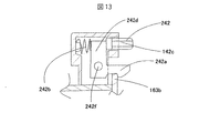
次に図13と図14とを用いて本発明の第2の実施形態を説明する。図13は、ボタン部の構成図である。図14は、サイクロン分離筒104と集塵ケース105の外観斜視図である。なお、本実施形態では、実施例1と同一符号のものは同一構造を有し、その説明は省略する。   Next, a second embodiment of the present invention will be described with reference to FIGS. FIG. 13 is a configuration diagram of the button unit. FIG. 14 is an external perspective view of the cyclone separating cylinder 104 and the dust collecting case 105. In the present embodiment, the same reference numerals as those in the first embodiment have the same structure, and the description thereof is omitted.

係止部242aは、バネ242bにより該係止部242aと係合部163bが係止するように付勢されており、フィルター枠140とフィルター枠163は集塵ケース105側に気密状態を保つように係止している。なお、係止部242aと係合部163bの形状は、鉤状とするとなおよい。   The locking portion 242a is biased by the spring 242b so that the locking portion 242a and the engaging portion 163b are locked, and the filter frame 140 and the filter frame 163 are kept airtight on the dust collecting case 105 side. It is locked to. The shapes of the locking portion 242a and the engaging portion 163b are preferably a bowl shape.

フィルター枠163の上方には、取っ手102付近にボタン242が設けられ、このボタン242を押すことにより、係止部242aが回転し、この係止部242aと、フィルター枠163に設けている係合部163bとが開放され、フィルター枠140とフィルター枠163が開放されて、ゴミ捨てが可能となる。ここでは、集塵部103を掃除機本体1に装着したときに、上ケース150や、上蓋102が邪魔となってボタン242を押せないようにするため、該ボタン242は水平方向に動くように設けている。また、ボタン242が水平方向に移動した際、このボタン242に押されて係止部242aは回転軸242fを中心として回動して、係合部163bを開放する様に動作する。なお、ボタン242はボタンケース242d、ガイド142cにより移動方向をガイドされるとともに、リブなどにより、ボタンケース242dから脱落するのを防止している。なお、このガイド242cによって、ボタン242がボタンケース242dから脱落するのを防ぐのを兼用すると、部品点数の増加を抑えられるので好ましい。   Above the filter frame 163, a button 242 is provided near the handle 102, and when the button 242 is pressed, the locking portion 242 a rotates, and the locking portion 242 a and the engagement provided on the filter frame 163. The part 163b is opened, and the filter frame 140 and the filter frame 163 are opened, so that dust can be discarded. Here, in order to prevent the button 242 from being pushed by the upper case 150 and the upper lid 102 being obstructed when the dust collecting unit 103 is attached to the cleaner body 1, the button 242 moves in the horizontal direction. Provided. Further, when the button 242 moves in the horizontal direction, it is pushed by the button 242, and the locking portion 242a rotates about the rotation shaft 242f to operate to release the engaging portion 163b. The button 242 is guided in the moving direction by the button case 242d and the guide 142c, and is prevented from falling off the button case 242d by a rib or the like. Note that it is preferable that the guide 242c also serves to prevent the button 242 from falling off the button case 242d because an increase in the number of parts can be suppressed.

また、係止部142aの移動はボタン142による摩擦力を利用しているので、これらの部材には摩擦摩耗特性に優れ、長時間の摺動特性に優れたポリオキシメチレン(POM)を用いるのが好ましい。   Further, since the movement of the locking portion 142a uses the frictional force generated by the button 142, these members are made of polyoxymethylene (POM), which has excellent frictional wear characteristics and long-time sliding characteristics. Is preferred.

本発明の一実施の形態を示す電気掃除機の外観斜視図である。It is an external appearance perspective view of the vacuum cleaner which shows one embodiment of this invention. 図1に示した電気掃除機における掃除機本体の斜視図である。It is a perspective view of the vacuum cleaner main body in the electric vacuum cleaner shown in FIG. 図1に示した電気掃除機における掃除機本体の上蓋を開いた状態を示す斜視図である。It is a perspective view which shows the state which opened the upper cover of the vacuum cleaner main body in the electric vacuum cleaner shown in FIG. 図1に示した電気掃除機における掃除機本体内の上蓋を開いて、サイクロン分離筒と集塵ケースとを取り外した状態を示す斜視図である。It is a perspective view which shows the state which opened the upper cover in the vacuum cleaner main body in the vacuum cleaner shown in FIG. 1, and removed the cyclone separation cylinder and the dust collection case. 図1に示した掃除機本体の断側面図である。It is a cutaway side view of the cleaner body shown in FIG. 図5のA部拡大図である。It is the A section enlarged view of FIG. 空気の流れを示す模式図である。It is a schematic diagram which shows the flow of air. サイクロン分離筒104と集塵ケース105の外観斜視図である。2 is an external perspective view of a cyclone separating cylinder 104 and a dust collecting case 105. FIG. サイクロン分離筒104と集塵ケース105の縦断面図である。2 is a longitudinal sectional view of a cyclone separating cylinder 104 and a dust collecting case 105. FIG. サイクロン分離筒104と集塵ケース105の断面図である。2 is a cross-sectional view of a cyclone separating cylinder 104 and a dust collecting case 105. FIG. サイクロン分離筒104と集塵ケース105を排気側から見たときの側面図である。It is a side view when the cyclone separation cylinder 104 and the dust collection case 105 are seen from the exhaust side. ボタン部の構成図である。It is a block diagram of a button part. ボタン部の構成図である。It is a block diagram of a button part. サイクロン分離筒104と集塵ケース105の外観斜視図である。2 is an external perspective view of a cyclone separating cylinder 104 and a dust collecting case 105. FIG.

符号の説明Explanation of symbols

1…掃除機本体、101…下ケース、103…集塵部、104…サイクロン分離筒、105…集塵ケース、106…第1のフィルター、107…電動送風機、112…補助フィルター、115…入口管、117…連通口、120…排気口、131…内筒、140…フィルター枠、142…ボタン、142a…係止部、142b…バネ、145…連絡通路、146…サイクロン部流出口、150…上ケース、161…第2のフィルター、163…フィルター枠、163a…係合部。   DESCRIPTION OF SYMBOLS 1 ... Vacuum cleaner main body, 101 ... Lower case, 103 ... Dust collection part, 104 ... Cyclone separation cylinder, 105 ... Dust collection case, 106 ... First filter, 107 ... Electric blower, 112 ... Auxiliary filter, 115 ... Inlet pipe DESCRIPTION OF SYMBOLS 117 ... Communication port, 120 ... Exhaust port, 131 ... Inner cylinder, 140 ... Filter frame, 142 ... Button, 142a ... Locking part, 142b ... Spring, 145 ... Communication passage, 146 ... Cyclone part outlet, 150 ... Up Case, 161... Second filter, 163... Filter frame, 163 a.

Claims (4)

掃除機本体内から着脱可能な集塵ケースと、この集塵ケースを前記掃除機本体から取り外す際に集塵ケースを保持するために設けた保持部と、該集塵ケースから塵埃を廃棄するために開閉する蓋体と、前記保持部の近傍に前記蓋体を開放するためのボタンを設けた電気掃除機において、
前記集塵ケースを前記掃除機本体に装着したときに、前記ボタンが押せない位置に配置したことを特徴とする電気掃除機。
A dust collection case removable from the vacuum cleaner main body, a holding portion provided to hold the dust collection case when the dust collection case is removed from the vacuum cleaner main body, and a dust collecting case from the dust collection case In a vacuum cleaner provided with a lid that opens and closes, and a button for opening the lid in the vicinity of the holding portion,
An electric vacuum cleaner, wherein the vacuum cleaner is disposed at a position where the button cannot be pressed when the dust collecting case is attached to the main body of the vacuum cleaner.
請求項1において、
保持部を集塵ケースの上面に配置したことを特徴とする電気掃除機。
In claim 1,
A vacuum cleaner characterized in that the holding portion is arranged on the upper surface of the dust collecting case.
請求項1において、
ボタンの移動方向が略水平方向であることを特徴とする電気掃除機。
In claim 1,
A vacuum cleaner characterized in that the moving direction of the button is substantially horizontal.
掃除機本体内から着脱可能な集塵ケースと、この集塵ケースを前記掃除機本体から取り外す際に集塵ケースを保持するために設けた保持部と、該集塵ケースから塵埃を廃棄するために開閉する蓋体と、前記保持部の近傍に前記蓋体を開放するためのボタンを設けた電気掃除機において、
前記集塵ケースを前記掃除機本体に装着したときに、前記ボタンと該掃除機本体との間に人の指が入らないように前記集塵ケースを装着したことを特徴とする電気掃除機。
A dust collection case removable from the vacuum cleaner main body, a holding portion provided to hold the dust collection case when the dust collection case is removed from the vacuum cleaner main body, and a dust collecting case from the dust collection case In a vacuum cleaner provided with a lid that opens and closes, and a button for opening the lid in the vicinity of the holding portion,
An electric vacuum cleaner, wherein the dust collecting case is attached so that a human finger does not enter between the button and the cleaner main body when the dust collecting case is attached to the cleaner main body.
JP2004120989A 2004-04-16 2004-04-16 Electric vacuum cleaner Pending JP2005296532A (en)

Priority Applications (1)

Application Number Priority Date Filing Date Title
JP2004120989A JP2005296532A (en) 2004-04-16 2004-04-16 Electric vacuum cleaner

Applications Claiming Priority (1)

Application Number Priority Date Filing Date Title
JP2004120989A JP2005296532A (en) 2004-04-16 2004-04-16 Electric vacuum cleaner

Publications (1)

Publication Number Publication Date
JP2005296532A true JP2005296532A (en) 2005-10-27

Family

ID=35328773

Family Applications (1)

Application Number Title Priority Date Filing Date
JP2004120989A Pending JP2005296532A (en) 2004-04-16 2004-04-16 Electric vacuum cleaner

Country Status (1)

Country Link
JP (1) JP2005296532A (en)

Cited By (4)

* Cited by examiner, † Cited by third party
Publication number Priority date Publication date Assignee Title
JP2007229191A (en) * 2006-03-01 2007-09-13 Hitachi Appliances Inc Electric vacuum cleaner
JP2008000381A (en) * 2006-06-23 2008-01-10 Hitachi Appliances Inc Electric vacuum cleaner
JP2008093342A (en) * 2006-10-16 2008-04-24 Sharp Corp Electric vacuum cleaner
JP2011010982A (en) * 2009-07-06 2011-01-20 Mitsubishi Electric Corp Vacuum cleaner

Similar Documents

Publication Publication Date Title
JP7055381B2 (en) Dust collection chamber and suction head for vacuum cleaner
JP2010035954A (en) Vacuum cleaner
JP4521159B2 (en) Vacuum cleaner
JP4467473B2 (en) Vacuum cleaner
JP4557783B2 (en) Vacuum cleaner
JP2006340935A (en) Electric vacuum cleaner
JP4393287B2 (en) Vacuum cleaner
JP2005296532A (en) Electric vacuum cleaner
JP6158072B2 (en) Electric vacuum cleaner
JP4399200B2 (en) Vacuum cleaner
JP3922131B2 (en) Electric vacuum cleaner
JP2012000210A (en) Vacuum cleaner
JP2005021469A (en) Vacuum cleaner
JP4102642B2 (en) Electric vacuum cleaner
JP4902703B2 (en) Electric vacuum cleaner
JP4485537B2 (en) Vacuum cleaner
JP4408449B2 (en) Vacuum cleaner
JP4528641B2 (en) Vacuum cleaner
JP4399246B2 (en) Electric vacuum cleaner
JP3941628B2 (en) Electric vacuum cleaner
JP4919926B2 (en) Vacuum cleaner
JP4340593B2 (en) Electric vacuum cleaner
JP2005000331A (en) Vacuum cleaner
JP2008093277A (en) Electric vacuum cleaner
JP4663552B2 (en) Electric vacuum cleaner

Legal Events

Date Code Title Description
RD04 Notification of resignation of power of attorney

Free format text: JAPANESE INTERMEDIATE CODE: A7424

Effective date: 20060509

A621 Written request for application examination

Effective date: 20060929

Free format text: JAPANESE INTERMEDIATE CODE: A621

A711 Notification of change in applicant

Effective date: 20061005

Free format text: JAPANESE INTERMEDIATE CODE: A712

A521 Written amendment

Effective date: 20060929

Free format text: JAPANESE INTERMEDIATE CODE: A523

A977 Report on retrieval

Effective date: 20090205

Free format text: JAPANESE INTERMEDIATE CODE: A971007

A131 Notification of reasons for refusal

Free format text: JAPANESE INTERMEDIATE CODE: A131

Effective date: 20090210

A521 Written amendment

Free format text: JAPANESE INTERMEDIATE CODE: A523

Effective date: 20090406

A02 Decision of refusal

Effective date: 20090512

Free format text: JAPANESE INTERMEDIATE CODE: A02