JP2005293067A - Voltage regulator - Google Patents
Voltage regulator Download PDFInfo
- Publication number
- JP2005293067A JP2005293067A JP2004105353A JP2004105353A JP2005293067A JP 2005293067 A JP2005293067 A JP 2005293067A JP 2004105353 A JP2004105353 A JP 2004105353A JP 2004105353 A JP2004105353 A JP 2004105353A JP 2005293067 A JP2005293067 A JP 2005293067A
- Authority
- JP
- Japan
- Prior art keywords
- output
- voltage
- protection circuit
- overcurrent protection
- circuit
- Prior art date
- Legal status (The legal status is an assumption and is not a legal conclusion. Google has not performed a legal analysis and makes no representation as to the accuracy of the status listed.)
- Withdrawn
Links
Images
Landscapes
- Continuous-Control Power Sources That Use Transistors (AREA)
Abstract
Description
本発明は、半導体集積回路の定電圧電源回路等に用いるボルテージレギュレータに関するものであり、特にその過電流保護回路に関する。 The present invention relates to a voltage regulator used in a constant voltage power supply circuit of a semiconductor integrated circuit, and more particularly to an overcurrent protection circuit thereof.
ボルテージレギュレータの過電流保護回路は、垂下形あるいはフの字形の出力電流出力電圧特性を持たせることにより、出力端子の短絡などで発生する過電流による出力制御部の破損を防止するようにしている。 The overcurrent protection circuit of the voltage regulator has a drooping or U-shaped output current output voltage characteristic to prevent damage to the output control unit due to overcurrent that occurs when the output terminal is short-circuited. .
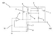
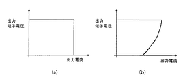
図4は、垂下形の出力特性を有する従来例のボルテージレギュレータである。図6(a)に示すような垂下形の出力特性を有する。
このボルテージレギュレータは、入力端子101と出力端子102の間に接続したトランジスタ1と、その出力電圧を抵抗7と抵抗8で分圧した電圧を+入力端子に接続し、かつ基準電圧源10の出力を−入力端子に接続した誤差増幅器9と、入力端子101と出力端子102の間に直列に接続したトランジスタ2と抵抗3の電流検出部と、その出力を反転し出力するトランジスタ44と抵抗5と、トランジスタ1のゲート−ソース間に接続したトランジスタ6とからなる。
FIG. 4 shows a conventional voltage regulator having a drooping output characteristic. It has a drooping output characteristic as shown in FIG.
In this voltage regulator, the
トランジスタ2のアスペクト比は、トランジスタ1のアスペクト比より小さく設定され、例えば1/10に設定されている。
従って、トランジスタ1およびトランジスタ2に流れる電流をI1およびI2、抵抗3の抵抗値をR3とするとき、出力電圧に比べ入力電圧が十分に高く、トランジスタ1およびトランジスタ2が共に飽和領域にあるときは、両トランジスタのソース−ドレイン間電圧はI2・R3だけ相違する。しかし、I1およびI2はゲート電位に依存するため、両者は比例の関係、すなわち上記例ではI1≒10・I2の関係にある。
The aspect ratio of the
Therefore, when the currents flowing through the
トランジスタ44の閾値電圧をVth4とすると、I2・R3≧Vth4、即ち
I1・R3/10≧Vth4 ・・・・・(1)
となる時、トランジスタ44がONする。これにより、トランジスタ44のドレイン端子の電位は出力電圧近くまで下がり、トランジスタ6がONしトランジスタ1のゲート電圧を入力電圧に引き上げることにより、トランジスタ1をOFFし過電流保護を行っている。(例えば、特許文献1)
図5は、フの字形の出力特性を有する従来例のボルテージレギュレータである。図6(b)に示すようなフの字形の出力特性を有する。
このボルテージレギュレータの回路は、電流検出部の出力を反転し出力するトランジスタ4のバックゲート端子が接地されている以外は、図4の回路と同様である。
通常の定電圧動作時にはトランジスタ4のバックゲートが接地されているため、バックゲート効果により(1)式で示すVth4が上昇し過電流検出レベルは高くなる。しかし、出力端子の短絡などにより出力電圧が接地電位まで低下した場合には、トランジスタ9のソースとバックゲートの電位が等しくなり、トランジスタ4の閾値電圧はバックゲートがソースに接続されている通常の値と等しくなる。
When the threshold voltage of the
The
FIG. 5 shows a conventional voltage regulator having a U-shaped output characteristic. It has a U-shaped output characteristic as shown in FIG.
The voltage regulator circuit is the same as the circuit of FIG. 4 except that the back gate terminal of the transistor 4 that inverts and outputs the output of the current detection unit is grounded.
Since the back gate of the transistor 4 is grounded during normal constant voltage operation, Vth4 expressed by the equation (1) rises due to the back gate effect, and the overcurrent detection level becomes high. However, when the output voltage drops to the ground potential due to a short circuit of the output terminal or the like, the potential of the source of the
従って、出力短絡時の電流に対し出力トランジスタを十分保護できるように抵抗3の値を定めておくことにより、通常動作時にはこれより大きな電流の流れる負荷を許容できるので、比較的小容量の定電圧電源で大きな負荷を駆動できる利点がある。(例えば、特許文献2)
しかしながら、従来のレギュレータの過充電保護回路には以下のような課題がある。
図4の回路では、過電流保護回路が動作し出力電圧が低下した場合においても、出力電流は変化しないため定電流性負荷の場合には出力制御トランジスタに大きな電流が流れ、短絡保護が不十分になりやすいという欠点を持つ。
However, the overcharge protection circuit of the conventional regulator has the following problems.
In the circuit of FIG. 4, even when the overcurrent protection circuit operates and the output voltage drops, the output current does not change. Therefore, in the case of a constant current load, a large current flows through the output control transistor and the short circuit protection is insufficient. It has the disadvantage that it tends to become.
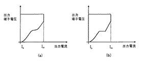
図5の回路では、前記の問題は解決されるものの、以下のような欠点を有する。この過電流保護回路の電流検出部が正確に出力電流を検出するには、トランジスタ1およびトランジスタ2が飽和領域で動作する必要がある。しかしながら、入出力電位差が小さい場合には、トランジスタ2の動作が飽和領域から外れ、図7(a)で示すように最大電流Imが変化してしまう。
The circuit shown in FIG. 5 has the following drawbacks although the above problem is solved. In order for the current detector of the overcurrent protection circuit to accurately detect the output current, the
また、トランジスタ4のバックゲートとソースの電位差を利用してフの字形の特性を実現しているため、図7(b)に示すとおり、最大出力電流Imと短絡電流Isとの差が出力電圧に依存する。したがって、ある最大出力電流Imにおける短絡電流Isを任意に設定できないという欠点があった。 Further, since the U-shaped characteristic is realized by utilizing the potential difference between the back gate and the source of the transistor 4, as shown in FIG. 7B, the difference between the maximum output current Im and the short-circuit current Is is the output voltage. Depends on. Therefore, there is a drawback that the short-circuit current Is at a certain maximum output current Im cannot be arbitrarily set.
さらに、負荷の条件によっては定電圧領域以外に安定点が存在し、起動時に出力電圧が過電流保護領域の安定点に留まってしまい、定電圧領域まで起動できないという問題が存在する。 Furthermore, there is a problem that a stable point exists outside the constant voltage region depending on the load condition, and the output voltage stays at the stable point in the overcurrent protection region at the time of start-up.
本発明は、垂下形出力特性を有する第1の過電流保護回路とフの字形出力特性を有する第2の過電流保護回路を具備し、負荷の短絡などによって出力端子に大電流が流れた場合に、出力電圧が高い時には第1の過電流保護回路が動作して出力電流を制限し、出力電圧が低下してきたら第2の過電流保護回路が動作して出力電流を最大出力電流以下に制限し、更に出力電圧が低下してきたら第2の過電流保護回路の過電流検出抵抗を大きくすることで更に出力電流を制限するような構成とした。 The present invention includes a first overcurrent protection circuit having a drooping output characteristic and a second overcurrent protection circuit having a U-shaped output characteristic, and a large current flows to an output terminal due to a short circuit of a load or the like In addition, when the output voltage is high, the first overcurrent protection circuit operates to limit the output current. When the output voltage decreases, the second overcurrent protection circuit operates to limit the output current below the maximum output current. If the output voltage further decreases, the output current is further limited by increasing the overcurrent detection resistance of the second overcurrent protection circuit.
以上のように本発明によれば、入出力電圧差によらず最大出力電流を高く設定でき、最大出力電流によらず短絡電流を低く設定でき、かつ起動時の条件にかかわらず出力電圧を定電圧領域まで安定して起動できるボルテージレギュレータを提供することができる。 As described above, according to the present invention, the maximum output current can be set high regardless of the input / output voltage difference, the short-circuit current can be set low regardless of the maximum output current, and the output voltage can be set regardless of the starting conditions. A voltage regulator that can be stably started up to the voltage range can be provided.
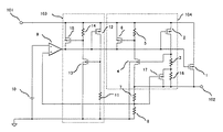
図1は、本発明の第1の実施例によるボルテージレギュレータのブロック図である。
入力端子101と出力端子102の間に接続されたトランジスタ1と、その出力電圧を抵抗7と抵抗8で分圧した電圧を+入力端子に接続され、かつ基準電圧源10の出力を−入力端子に接続された誤差増幅器9と、入力端子101と出力端子102の間に垂下形の入出力特性を持つ第1の過電流保護回路103とフの字形の入出力特性を持つ第2の過電流保護回路104を設けた構成となっている。トランジスタ1のゲート端子は誤差増幅器9の出力で制御され、トランジスタ1が出力電圧を制御するトランジスタとして働く。
FIG. 1 is a block diagram of a voltage regulator according to a first embodiment of the present invention.
The
第1の過電流保護回路103の電流検出部は、入力端子101とGND端子の間に直列接続されたトランジスタ12と抵抗11によって構成される。また、第2の過電流保護回路104の電流検出部は、入力端子101と出力端子102の間に直列接続されたトランジスタ2、抵抗3、抵抗16と抵抗16に並列に接続されたトランジスタ17によって構成される。トランジスタ17のゲートは、出力電圧を抵抗7と抵抗8で分圧した電圧が接続される。
The current detection unit of the first
次に動作について説明する。
正常動作状態では、第2の過電流保護回路104はトランジスタ17がONしていて抵抗3のみで過電流を検出している。この状態で、第1の過電流保護回路103の検出電流は、第2の過電流保護回路104の検出電流よりも低く設定されている。
出力端子102より負荷に、設定した最大電流を超える過電流が流れた場合、第1の過電流保護回路103および第2の過電流保護回路104が動作する。この時、検出電流が低く設定されている第1の過電流保護回路103が働き、出力端子102の出力はある電圧になるまで垂下形の出力特性となる。
Next, the operation will be described.
In the normal operation state, the second
When an overcurrent exceeding the set maximum current flows from the
第1の過電流保護回路103が働き出力端子102の出力電圧が下がることによって、第2の過電流保護回路104の検出電流も低下していく。第2の過電流保護回路104の検出電流が第1の過電流保護回路103の検出電流よりも低下した電圧から、出力端子102の出力はフの字形の出力特性となる。
As the first
さらに出力端子102の電圧が低下すると、トランジスタ17のゲート電圧も下がり、トランジスタ17は徐々にOFFになる。これにより、抵抗3と抵抗16が直列となり、検出電流はトランジスタ17がONした状態の検出電流よりもさらに低い値となる。
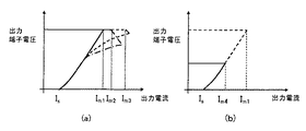
このような動作により、図3(a)のような出力電圧電流特性が得られるので、入出力電圧差によらず最大電流を高くかつ短絡電流を低く設定でき、更に起動時の条件にかかわらず出力電圧を定電圧領域まで起動できるボルテージレギュレータを提供すること可能となる。
When the voltage at the
By such an operation, the output voltage current characteristic as shown in FIG. 3A can be obtained, so that the maximum current can be set high and the short circuit current can be set low regardless of the input / output voltage difference. It is possible to provide a voltage regulator capable of starting the output voltage up to a constant voltage region.
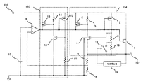
図2は、本発明の第1の実施例によるボルテージレギュレータのブロック図である。
入力端子101と出力端子102の間に接続されたトランジスタ1と、その出力電圧を抵抗7と抵抗8で分圧した電圧を+入力端子に接続され、かつ基準電圧源10の出力を−入力端子に接続された誤差増幅器9と、入力端子101と出力端子102の間に垂下形の入出力特性を持つ第1の過電流保護回路103とフの字形の入出力特性を持つ第2の過電流保護回路104を設けた構成となっている。トランジスタ1のゲート端子は誤差増幅器9の出力で制御され、トランジスタ1が出力電圧を制御するトランジスタとして働く。
FIG. 2 is a block diagram of a voltage regulator according to the first embodiment of the present invention.
The
第1の過電流保護回路103の電流検出部は、入力端子101とGND端子の間に直列接続されたトランジスタ12と抵抗11によって構成される。また、第2の過電流保護回路104の電流検出部は、入力端子101と出力端子102の間に直列接続されたトランジスタ2、抵抗3、抵抗16と抵抗16に並列に接続されたスイッチ素子18によって構成される。スイッチ素子18は、出力端子102の電圧をモニタする電圧検出器19によって制御される。
The current detection unit of the first
次に動作について説明する。
正常動作状態では、第2の過電流保護回路104はスイッチ素子18がONしていて抵抗3のみで過電流を検出している。この状態で、第1の過電流保護回路103の検出電流は、第2の過電流保護回路104の検出電流よりも低く設定されている。
出力端子102より負荷に、設定した最大電流を超える過電流が流れた場合、第1の過電流保護回路103および第2の過電流保護回路104が動作する。この時、検出電流が低く設定されている第1の過電流保護回路103が働き、出力端子102の出力はある電圧になるまで垂下形の出力特性となる。
Next, the operation will be described.
In the normal operation state, the second
When an overcurrent exceeding the set maximum current flows from the
第1の過電流保護回路103が働き出力端子102の出力電圧が下がることによって、第2の過電流保護回路104の検出電流も低下していく。第2の過電流保護回路104の検出電流が第1の過電流保護回路103の検出電流よりも低下した電圧から、出力端子102の出力はフの字形の出力特性となる。
As the first
さらに出力端子102の電圧が低下すると、電圧検出器19が動作しスイッチ素子18をOFFする。これにより、抵抗3と抵抗16が直列となり、検出電流はスイッチ素子18がONした状態の検出電流よりもさらに低い値となる。
When the voltage at the
このような動作により、図3(b)のような出力電圧電流特性が得られるので、入出力電圧差によらず最大電流を高くかつ短絡電流を低く設定でき、更に起動時の条件にかかわらず出力電圧を定電圧領域まで起動できるボルテージレギュレータを提供すること可能となる。 By such an operation, the output voltage current characteristic as shown in FIG. 3B can be obtained. Therefore, the maximum current can be set high and the short-circuit current can be set low regardless of the input / output voltage difference. It is possible to provide a voltage regulator capable of starting the output voltage up to a constant voltage region.
本実施例ではフの字形過電流保護回路の検出抵抗をスイッチ素子18により制御したが、ON/OFFを行うのではなく徐々に抵抗値が変化するような回路でも本発明が適用されることは明白である。
In this embodiment, the detection resistance of the U-shaped overcurrent protection circuit is controlled by the
1,2,6,12,15,17・・・・P−MOSトランジスタ
4,44,13・・・・N−MOSトランジスタ
3,5,7,8,11,14,16 ・・・・抵抗
9 ・・・・誤差増幅器
10 ・・・・基準電圧源
18 ・・・・スイッチ素子
19 ・・・・電圧検出回路
101 ・・・・入力端子
102 ・・・・出力端子
103 ・・・・第1の過電流保護回路
104 ・・・・第2の過電流保護回路
1, 2, 6, 12, 15, 17... P-
Claims (10)
ソースに前記入力端子を接続しゲートに前記誤差増幅器の出力を接続した第1の電流検出用P−MOSトランジスタと、前記第1の電流検出用P−MOSトランジスタのドレインと前記GNDの間に接続した第1の電流検出抵抗と、前記入力端子と前記GNDの間に接続した前記第1の電流検出抵抗の出力を反転出力する第1の反転回路と、ソースに前記入力端子を接続しドレインに前記誤差増幅器の出力を接続しゲートに前記第1の反転回路の出力を接続した第1の制御用P−MOSトランジスタとからなる第1の過電流保護回路と、
ソースに前記入力端子を接続しゲートに前記誤差増幅器の出力を接続した第2の電流検出用P−MOSトランジスタと、前記第2の電流検出用P−MOSトランジスタのドレインと前記GNDの間に接続した前記出力電圧によって抵抗値が可変する第2の電流検出抵抗と、少なくともソースに前記出力端子を接続しゲートに前記第2の電流検出抵抗の出力を接続しバックゲートに前記GNDを接続したN−MOSトランジスタからなり前記第2の電流検出抵抗の出力を反転出力する第2の反転回路と、ソースに前記入力端子を接続しドレインに前記誤差増幅器の出力を接続しゲートに前記第2の反転回路の出力を接続した第2の制御用P−MOSトランジスタとからなる第2の過電流保護回路と、を設けたことを特徴とするボルテージレギュレータ。 Voltage is divided between the input terminal, the output terminal, the output P-MOS transistor having the source connected to the input terminal and the drain connected to the output terminal, and the output terminal connected between the output terminal and GND. A voltage dividing resistor, a reference voltage source, an error amplifier for inputting the output of the voltage dividing resistor and the output of the reference voltage source, and a voltage for connecting the output of the error amplifier to the gate of the output P-MOS transistor In the regulator,
A first current detection P-MOS transistor having the input terminal connected to the source and the output of the error amplifier connected to the gate, and connected between the drain of the first current detection P-MOS transistor and the GND. The first current detection resistor, the first inverting circuit for inverting the output of the first current detection resistor connected between the input terminal and the GND, and the input terminal connected to the source and the drain A first overcurrent protection circuit comprising a first control P-MOS transistor connected to the output of the error amplifier and connected to the gate of the output of the first inversion circuit;
A second current detection P-MOS transistor having the input terminal connected to the source and the output of the error amplifier connected to the gate, and connected between the drain of the second current detection P-MOS transistor and the GND. A second current detection resistor whose resistance value is variable according to the output voltage, and at least a source connected to the output terminal, a gate connected to the output of the second current detection resistor, and a back gate connected to the GND. A second inverting circuit comprising a MOS transistor for inverting and outputting the output of the second current detection resistor, the input terminal connected to the source, the output of the error amplifier connected to the drain, and the second inverting circuit connected to the gate And a second overcurrent protection circuit comprising a second control P-MOS transistor to which the output of the circuit is connected. Over data.
Priority Applications (1)
| Application Number | Priority Date | Filing Date | Title |
|---|---|---|---|
| JP2004105353A JP2005293067A (en) | 2004-03-31 | 2004-03-31 | Voltage regulator |
Applications Claiming Priority (1)
| Application Number | Priority Date | Filing Date | Title |
|---|---|---|---|
| JP2004105353A JP2005293067A (en) | 2004-03-31 | 2004-03-31 | Voltage regulator |
Publications (1)
| Publication Number | Publication Date |
|---|---|
| JP2005293067A true JP2005293067A (en) | 2005-10-20 |
Family
ID=35325951
Family Applications (1)
| Application Number | Title | Priority Date | Filing Date |
|---|---|---|---|
| JP2004105353A Withdrawn JP2005293067A (en) | 2004-03-31 | 2004-03-31 | Voltage regulator |
Country Status (1)
| Country | Link |
|---|---|
| JP (1) | JP2005293067A (en) |
Cited By (9)
| Publication number | Priority date | Publication date | Assignee | Title |
|---|---|---|---|---|
| JP2007148561A (en) * | 2005-11-24 | 2007-06-14 | New Japan Radio Co Ltd | Stabilized power supply circuit |
| JP2008052516A (en) * | 2006-08-24 | 2008-03-06 | Seiko Instruments Inc | Constant voltage circuit |
| JP2009169503A (en) * | 2008-01-11 | 2009-07-30 | Ricoh Co Ltd | Overcurrent protection circuit and constant voltage circuit equipped with its overcurrent protection circuit |
| US7675725B2 (en) | 2006-11-13 | 2010-03-09 | Sharp Kabushiki Kaisha | Constant voltage output circuit |
| US7855537B2 (en) | 2006-11-07 | 2010-12-21 | Nec Electronics Corporation | Voltage supply circuit |
| CN102778914A (en) * | 2011-05-12 | 2012-11-14 | 精工电子有限公司 | Voltage regulator |
| CN103226370A (en) * | 2012-01-31 | 2013-07-31 | 精工电子有限公司 | Voltage regulator |
| CN103576729A (en) * | 2012-07-26 | 2014-02-12 | 精工电子有限公司 | Voltage regulator |
| CN112099560A (en) * | 2020-09-25 | 2020-12-18 | 上海华虹宏力半导体制造有限公司 | Linear voltage stabilizer |
-
2004
- 2004-03-31 JP JP2004105353A patent/JP2005293067A/en not_active Withdrawn
Cited By (17)
| Publication number | Priority date | Publication date | Assignee | Title |
|---|---|---|---|---|
| JP2007148561A (en) * | 2005-11-24 | 2007-06-14 | New Japan Radio Co Ltd | Stabilized power supply circuit |
| JP2008052516A (en) * | 2006-08-24 | 2008-03-06 | Seiko Instruments Inc | Constant voltage circuit |
| US7855537B2 (en) | 2006-11-07 | 2010-12-21 | Nec Electronics Corporation | Voltage supply circuit |
| US7675725B2 (en) | 2006-11-13 | 2010-03-09 | Sharp Kabushiki Kaisha | Constant voltage output circuit |
| JP2009169503A (en) * | 2008-01-11 | 2009-07-30 | Ricoh Co Ltd | Overcurrent protection circuit and constant voltage circuit equipped with its overcurrent protection circuit |
| US9110487B2 (en) | 2011-05-12 | 2015-08-18 | Seiko Instruments Inc. | Voltage regulator |
| CN102778914A (en) * | 2011-05-12 | 2012-11-14 | 精工电子有限公司 | Voltage regulator |
| CN102778914B (en) * | 2011-05-12 | 2015-09-02 | 精工电子有限公司 | Voltage regulator |
| CN103226370B (en) * | 2012-01-31 | 2016-06-15 | 精工半导体有限公司 | Voltage regulator |
| KR20130088800A (en) | 2012-01-31 | 2013-08-08 | 세이코 인스트루 가부시키가이샤 | Voltage regulator |
| CN103226370A (en) * | 2012-01-31 | 2013-07-31 | 精工电子有限公司 | Voltage regulator |
| US9459641B2 (en) | 2012-01-31 | 2016-10-04 | Sii Semiconductor Corporation | Voltage regulator |
| KR102007630B1 (en) * | 2012-01-31 | 2019-08-06 | 에이블릭 가부시키가이샤 | Voltage regulator |
| CN103576729A (en) * | 2012-07-26 | 2014-02-12 | 精工电子有限公司 | Voltage regulator |
| CN103576729B (en) * | 2012-07-26 | 2016-01-20 | 精工电子有限公司 | Voltage regulator |
| TWI575350B (en) * | 2012-07-26 | 2017-03-21 | Sii Semiconductor Corp | Voltage regulator |
| CN112099560A (en) * | 2020-09-25 | 2020-12-18 | 上海华虹宏力半导体制造有限公司 | Linear voltage stabilizer |
Similar Documents
| Publication | Publication Date | Title |
|---|---|---|
| JP5421133B2 (en) | Voltage regulator | |
| JP3983612B2 (en) | Stabilized power supply with current limiting function | |
| US8547079B2 (en) | Voltage regulator capable of enabling overcurrent protection in a state in which an output current is large | |
| JP5279544B2 (en) | Voltage regulator | |
| JP5047815B2 (en) | Overcurrent protection circuit and constant voltage circuit having the overcurrent protection circuit | |
| JP2017523530A (en) | Short circuit protection for voltage regulator | |
| US9063558B2 (en) | Current limiting circuit configured to limit output current of driver circuit | |
| US7233462B2 (en) | Voltage regulator having overcurrent protection circuit | |
| US9740222B2 (en) | Overcurrent protection circuit for controlling a gate of an output transistor based on an output current | |
| US6870351B2 (en) | Voltage regulator circuit and integrated circuit device including the same | |
| JP4805643B2 (en) | Constant voltage circuit | |
| JP4169670B2 (en) | Output control circuit, constant voltage source IC and electronic device | |
| US8493097B2 (en) | Current-sensing circuit | |
| JP2005293067A (en) | Voltage regulator | |
| JP4439974B2 (en) | Power supply voltage monitoring circuit | |
| JP2005241463A (en) | Current detection circuit and protection circuit | |
| JP4319012B2 (en) | Overcurrent protection circuit and voltage regulator | |
| JP2009011112A (en) | Overcurrent protection circuit and electronic equipment using the same | |
| JP2007128292A (en) | Voltage regulator | |
| JP2009282908A (en) | Regulator | |
| JP4550506B2 (en) | DC stabilized power supply circuit | |
| JP4403288B2 (en) | Regulator circuit | |
| JP4225615B2 (en) | Short circuit protection circuit | |
| JP2007184677A (en) | Switch circuit and overcurrent detection circuit therefor | |
| JP3900731B2 (en) | Power switch circuit |
Legal Events
| Date | Code | Title | Description |
|---|---|---|---|
| A621 | Written request for application examination |
Free format text: JAPANESE INTERMEDIATE CODE: A621 Effective date: 20070328 |
|
| A977 | Report on retrieval |
Free format text: JAPANESE INTERMEDIATE CODE: A971007 Effective date: 20091022 |
|
| A131 | Notification of reasons for refusal |
Free format text: JAPANESE INTERMEDIATE CODE: A131 Effective date: 20091027 |
|
| RD01 | Notification of change of attorney |
Free format text: JAPANESE INTERMEDIATE CODE: A7421 Effective date: 20091113 |
|
| A761 | Written withdrawal of application |
Free format text: JAPANESE INTERMEDIATE CODE: A761 Effective date: 20091211 |
