JP2005291493A - Air pulser - Google Patents
Air pulser Download PDFInfo
- Publication number
- JP2005291493A JP2005291493A JP2004374012A JP2004374012A JP2005291493A JP 2005291493 A JP2005291493 A JP 2005291493A JP 2004374012 A JP2004374012 A JP 2004374012A JP 2004374012 A JP2004374012 A JP 2004374012A JP 2005291493 A JP2005291493 A JP 2005291493A
- Authority
- JP
- Japan
- Prior art keywords
- chamber
- air
- valve
- valve body
- valve plate
- Prior art date
- Legal status (The legal status is an assumption and is not a legal conclusion. Google has not performed a legal analysis and makes no representation as to the accuracy of the status listed.)
- Pending
Links
- 238000002347 injection Methods 0.000 claims abstract description 31
- 239000007924 injection Substances 0.000 claims abstract description 31
- 238000005192 partition Methods 0.000 claims description 5
- 239000000243 solution Substances 0.000 abstract 1
- 230000002093 peripheral effect Effects 0.000 description 9
- 238000007789 sealing Methods 0.000 description 8
- 238000001179 sorption measurement Methods 0.000 description 5
- 239000008187 granular material Substances 0.000 description 4
- 230000007423 decrease Effects 0.000 description 2
- 230000015572 biosynthetic process Effects 0.000 description 1
- 230000006835 compression Effects 0.000 description 1
- 238000007906 compression Methods 0.000 description 1
- 239000000470 constituent Substances 0.000 description 1
- 239000012530 fluid Substances 0.000 description 1
- 239000000696 magnetic material Substances 0.000 description 1
- 239000002245 particle Substances 0.000 description 1
- 239000000843 powder Substances 0.000 description 1
- 238000009423 ventilation Methods 0.000 description 1
Images
Landscapes
- Fluid-Driven Valves (AREA)
- Magnetically Actuated Valves (AREA)
Abstract
Description
この発明は、パルスエアを噴射するエアパルサに関するものである。 The present invention relates to an air pulser that injects pulsed air.
間歇的に噴射される圧縮エア、所謂パルスエアによって粉粒体を空気輸送したり、ホッパ内に充填された粉粒体のブリッジを破壊したりすることは従来から普通に行なわれている。 Conventionally, it is common practice to pneumatically transport the granular material by compressed air jetted intermittently, so-called pulsed air, or to destroy the bridge of the granular material filled in the hopper.
例えば、特許文献1に記載された粉粒体の輸送装置においては、コンプレッサから成る圧縮空気供給源と加圧タンクとを第1通路で連通し、加圧タンクの下部出口に接続された粉粒体の輸送管と前記圧縮空気供給源とを第2通路で連通し、前記第1通路と第2通路のそれぞれに電磁弁を接続し、各電磁弁の開閉を制御装置で制御して、加圧タンク内および輸送管内にパルスエアを交互に供給し、加圧タンク内に供給されるパルスエアにより内部の粉粒体を流動化させてブリッジの発生を抑制するようにしている。また、輸送管内に供給されるパルスエアによって、加圧タンク内から輸送管内に排出される粉粒体を空気輸送するようにしている。 For example, in the granular material transport apparatus described in Patent Document 1, a compressed air supply source composed of a compressor and a pressurized tank communicate with each other through a first passage and are connected to a lower outlet of the pressurized tank. A body transport pipe and the compressed air supply source are communicated with each other through a second passage, and an electromagnetic valve is connected to each of the first passage and the second passage. Pulse air is alternately supplied into the pressure tank and the transport pipe, and the internal powder particles are fluidized by the pulse air supplied into the pressure tank to suppress the occurrence of bridges. In addition, the granular material discharged from the pressurized tank into the transport pipe is pneumatically transported by pulsed air supplied into the transport pipe.
また、特許文献2に記載されたエアバイブレータにおいては、シリンダの上方にバルブ室を設け、そのバルブ室内に小孔を有するダイヤフラムを張設して、バルブ室を上室と圧縮エアが供給される下室とに仕切り、上室の周壁に形成された排気口に電磁弁を接続し、この電磁弁の開閉を制御し、電磁弁の開放により上室内の圧縮エアを外部に排気し、上室内の圧縮低下によりダイヤフラムを上室側にわん曲させてシリンダの上端を開口し、下室からシリンダ内に供給されるパルスエアによって、そのシリンダ内に組込まれたピストンを下降させ、このピストンにより打撃プレートを打撃するようにしている。
Further, in the air vibrator described in
ところで、上記のような噴流体の輸送装置やエアバイブレータにおいては、パルスエアの形成に電磁弁を必要とするため、装置が大型化すると共に、電磁弁の開閉を制御装置で制御する必要があるため、コストが高くつくという不都合がある。そのような不都合を解消するため、本件出願人は、電磁弁を用いることなく圧縮エアを連続的に供給するのみでパルスエアを噴射させることができるようにしたエアパルサを特許文献3で提案している。
By the way, in the jet fluid transport apparatus and the air vibrator as described above, an electromagnetic valve is required for the formation of pulsed air. Therefore, the apparatus is enlarged and the opening / closing of the electromagnetic valve needs to be controlled by the control device. There is a disadvantage that the cost is high. In order to eliminate such inconvenience, the present applicant has proposed an air pulser in
上記特許文献3に記載されたエアパルサは、ボディの内部空間をダイヤフラムによって給気チャンバと排気チャンバとに仕切り、給気チャンバ内には前記ダイヤフラムによって開閉されるエア噴射筒を設け、排気チャンバ内には、その排気チャンバを第1室と第2室に仕切る弁プレートを設け、第2室には弁プレートに形成された弁孔を開閉する弁体を組込み、その弁体に保持された永久磁石が弁プレートに吸着する作用によって弁体を閉鎖位置に保持するように構成されている。
The air pulser described in
そして、上記ボディに形成された給気口から給気チャンバ内に供給される圧縮エアをダイヤフラムに形成された小孔から第1室内に流入させ、その第1室内の圧力が永久磁石の吸着力より高くなったとき、弁体を後退させて排気チャンバ内の圧縮エアを排気口から外部に流出させ、その流出による排気チャンバ内の圧力低下によりダイヤフラムを排気チャンバ側に変形させて、給気チャンバ内の圧縮エアをエア噴射筒から噴射させるようにしている。 Then, compressed air supplied into the air supply chamber from the air supply port formed in the body is caused to flow into the first chamber from a small hole formed in the diaphragm, and the pressure in the first chamber is adjusted to the attractive force of the permanent magnet. When it becomes higher, the valve body is moved backward to let the compressed air in the exhaust chamber flow out to the outside from the exhaust port, and the diaphragm is deformed to the exhaust chamber side due to the pressure drop in the exhaust chamber due to the outflow, and the air supply chamber The compressed air inside is injected from the air injection cylinder.
ところで、上記特許文献3に記載されたエアパルサにおいては、弁体が弁プレートの弁孔を閉鎖する状態で、第1室内の高圧エアが弁体と弁プレートの対向部間から第2室に漏洩すると、第1室の圧力を上昇させることができなくなり、パルスエアを噴射させることができなくなる。
By the way, in the air pulser described in
そこで、上記エアパルサにおいては、弁プレートの弁体に対する対向面に、弁体の先端部が挿入される凹部を設け、その凹部の内周に形成されたリング溝内にOリングを組込み、弁体が閉鎖状態とされたとき、Oリングの内周を弁体の先端部外周に形成されたテーパ面に接触させて弁プレートと弁体の対向部間をシールするようにしているが、Oリングの内周を全体にわたって弁体のテーパ面に接触させることが実際問題として困難であり、微妙に発生するエア漏れのため、エアパルサを精度よく作動させることができず、改良すべき点が残されていた。
この発明の課題は、上記のようなエアパルサにおいて、永久磁石の吸着によって閉鎖状態に保持される弁体と弁プレートの対向面間から第2室へのエア漏れを確実に防止することである。 An object of the present invention is to reliably prevent air leakage from the space between the opposed surfaces of the valve body and the valve plate held in the closed state by the adsorption of the permanent magnet to the second chamber in the above air pulser.
上記の課題を解決するために、この発明においては、ボディの内部空間内に小孔を有するダイヤフラムを張設して、内部空間を給気チャンバと排気チャンバとに仕切り、給気チャンバ内にはダイヤフラムによって開閉されるエア噴射筒を設け、排気チャンバ内には、その排気チャンバを第1室と第2室とに仕切る弁プレートを設け、第1室にはダイヤフラムがエア噴射筒を閉じる方向にダイヤフラムを変形させるスプリングを設け、第2室には、弁プレートに形成された弁孔の開閉用の弁体と、その弁体を弁プレートに対して移動自在に支持するガイド筒とを組込み、ガイド筒の両端部にはその内部と第2室を連通する通気孔を形成し、弁体には前記弁プレートに吸着して弁体を閉鎖状態に保持する永久磁石を設け、ボディには給気チャンバに圧縮エアを供給する給気口と、第2室内のエアを外部に排気する排気口を形成したエアパルサにおいて、弁プレートとガイド筒の対向面間にシール部材を組込み、そのシール部材の内周に弁体の先端部外周に形成されたテーパ面と弾性接触する環状のシールリップを設け、ガイド筒の先端部内周にはシールリップがガイド筒内に向けて弾性変形するのを防止する環状突出部を設けた構成を採用したのである。 In order to solve the above problems, in the present invention, a diaphragm having a small hole is stretched in the internal space of the body, and the internal space is partitioned into an air supply chamber and an exhaust chamber, An air injection cylinder that is opened and closed by a diaphragm is provided, and a valve plate that divides the exhaust chamber into a first chamber and a second chamber is provided in the exhaust chamber, and the diaphragm closes the air injection cylinder in the first chamber. A spring for deforming the diaphragm is provided, and in the second chamber, a valve body for opening and closing a valve hole formed in the valve plate and a guide cylinder for supporting the valve body movably with respect to the valve plate are incorporated. At both ends of the guide cylinder, vent holes are formed to communicate the interior with the second chamber. The valve body is provided with a permanent magnet that is attracted to the valve plate and holds the valve body in a closed state. Air chamber In an air pulser formed with an air supply port for supplying compressed air and an exhaust port for exhausting the air in the second chamber to the outside, a seal member is incorporated between the opposing surfaces of the valve plate and the guide cylinder, and the inner periphery of the seal member An annular projecting portion that provides an annular seal lip that elastically contacts the tapered surface formed on the outer periphery of the tip of the valve body, and prevents the seal lip from elastically deforming toward the guide tube on the inner periphery of the guide tube The configuration provided with is adopted.
上記の課題を解決するもう1つの手段として、ボディの内部空間内に小孔を有するダイヤフラムを張設して、内部空間を給気チャンバと排気チャンバとに仕切り、給気チャンバ内にはダイヤフラムによって開閉されるエア噴射筒を設け、排気チャンバ内には、その排気チャンバを第1室と第2室とに仕切る弁プレートを設け、第1室にはダイヤフラムがエア噴射筒を閉じる方向にダイヤフラムを変形させるスプリングを設け、第2室には、弁プレートに形成された弁孔の開閉用の弁体と、その弁体を弁プレートに対して移動自在に支持するガイド筒とを組込み、ガイド筒の両端部にはその内部と第2室を連通する通気孔を形成し、弁体には弁プレートに吸着して弁体を閉鎖状態に保持する永久磁石を設け、ボディには給気チャンバに圧縮エアを供給する給気口と、第2室内のエアを外部に排気する排気口とを形成したエアパルサにおいて、弁プレートとガイド筒の対向面間にシール部材を組込み、弁体の先端部外周に異径段部を形成し、この異径段部と弾性接触する環状のシールリップをシール部材の内周部に設けた構成を採用することもできる。 As another means for solving the above problem, a diaphragm having a small hole is stretched in the internal space of the body, and the internal space is divided into an air supply chamber and an exhaust chamber, and the air supply chamber is separated by a diaphragm. An air injection cylinder that is opened and closed is provided, and a valve plate that divides the exhaust chamber into a first chamber and a second chamber is provided in the exhaust chamber, and the diaphragm is disposed in the first chamber in a direction in which the diaphragm closes the air injection cylinder. A spring to be deformed is provided, and a valve body for opening and closing a valve hole formed in the valve plate and a guide cylinder for movably supporting the valve body with respect to the valve plate are incorporated in the second chamber. Ventilation holes communicating with the interior of the chamber and the second chamber are formed at both ends, and a permanent magnet for holding the valve body in a closed state by adsorbing to the valve plate is provided on the valve body. Compressed air In an air pulsar formed with an air supply port to supply and an exhaust port for exhausting the air in the second chamber to the outside, a seal member is incorporated between the opposing surfaces of the valve plate and the guide cylinder, and the outer diameter of the tip of the valve body is different. It is also possible to adopt a configuration in which a stepped portion is formed and an annular seal lip that elastically contacts the stepped portion of different diameter is provided on the inner peripheral portion of the seal member.
上記第1、第2のいずれかの発明のエアパルサも、上記ボディの内部機構の作用により所望のパルス間隔でパルスエアが供給される。給気口から給気チャンバ内に圧縮エアを供給すると、その圧縮エアはダイヤフラムに形成された小孔から排気チャンバの第1室内に流入し、その第1室内の圧力が永久磁石の吸着力より高くなると弁体が後退して弁孔を開放し、第1室内の圧縮エアが弁孔から第2室に流れて排気口から外部に排出される。 In the air pulsar of either the first or second invention, pulsed air is supplied at a desired pulse interval by the action of the internal mechanism of the body. When compressed air is supplied into the air supply chamber from the air supply port, the compressed air flows into the first chamber of the exhaust chamber through a small hole formed in the diaphragm, and the pressure in the first chamber is determined by the adsorption force of the permanent magnet. When it becomes higher, the valve body moves backward to open the valve hole, and the compressed air in the first chamber flows from the valve hole to the second chamber and is discharged to the outside through the exhaust port.
その排気によって排気チャンバ内の圧力が給気チャンバ内の圧力より低くなるため、ダイヤフラムは排気チャンバ側に変形し、エア噴射筒のエア入口が開放される。このため、給気チャンバ内の圧縮エアはエア噴射筒内に流れて、そのエア噴射筒から噴射される。また、排気チャンバ内の圧力がほぼ大気圧に保持されると、永久磁石と弁プレートの相互間に作用する吸着力によって弁体が弁孔を閉じる状態に戻り、その弁体の閉鎖後、ダイヤフラムは給気チャンバ側に変形してエア噴射筒のエア入口を閉じ、給気チャンバからエア噴射筒への圧縮エアの流動を遮断する。弁体は排気チャンバの第1室の圧力上昇の都度開放し、その弁体が開放するたびにダイヤフラムは排気チャンバ側に変形してエア噴射筒のエア入口を開放するため、エア噴射筒からパルスエアを間歇的に噴射することができる。 Due to the exhaust, the pressure in the exhaust chamber becomes lower than the pressure in the air supply chamber, so that the diaphragm is deformed to the exhaust chamber side and the air inlet of the air injection cylinder is opened. For this reason, the compressed air in the air supply chamber flows into the air injection cylinder and is injected from the air injection cylinder. Further, when the pressure in the exhaust chamber is maintained at almost atmospheric pressure, the valve body returns to the state of closing the valve hole by the attractive force acting between the permanent magnet and the valve plate, and after closing the valve body, the diaphragm Deforms to the air supply chamber side, closes the air inlet of the air injection cylinder, and blocks the flow of compressed air from the air supply chamber to the air injection cylinder. The valve body is released each time the pressure in the first chamber of the exhaust chamber rises. Each time the valve body is opened, the diaphragm is deformed to the exhaust chamber side to open the air inlet of the air injection cylinder. Can be intermittently injected.
このようなエアパルサの基本作用を確保するためには、永久磁石の吸着によって閉鎖状態に保持される弁体と弁プレートの対向面間から第2室へのエア漏れを防止する必要があるが、上記いずれの発明でも弁プレートとガイド筒の対向面間にシール部材を組込み、このシール部材にシールリップを設け、このシールリップの弾性力で第2室へのエア漏れを防止するようにしている。このため、シール作用が弁体の全周に亘って確保され、エア漏れが確実に防止される。 In order to ensure the basic action of such an air pulser, it is necessary to prevent air leakage from the space between the opposed surfaces of the valve body and the valve plate held in a closed state by the adsorption of the permanent magnet to the second chamber. In any of the above-described inventions, a seal member is incorporated between the opposed surfaces of the valve plate and the guide cylinder, and a seal lip is provided on the seal member so that air leakage into the second chamber is prevented by the elastic force of the seal lip. . For this reason, a sealing action is ensured over the entire circumference of the valve body, and air leakage is reliably prevented.
上記のように、第1の発明のエアパルサではシール部材の内周に弁体の先端部外周に形成されたテーパ面に弾性接触する環状のシールリップを設けることにより、弁体の閉鎖状態で上記シールリップが弁体のテーパ面に弾性接触すると共に、第1室内の圧力が高くなると、テーパ面に対するシールリップの接触圧力がさらに増大するため、きわめて良好なシール性を得ることができ、弁体と弁プレートの対向面間から第2室へのエア漏れを確実に防止することができる。このため、エアパルサをきわめて高精度に作動させることができる。 As described above, in the air pulser of the first invention, the annular seal lip that elastically contacts the tapered surface formed on the outer periphery of the tip of the valve body is provided on the inner periphery of the seal member. When the seal lip is in elastic contact with the tapered surface of the valve body and the pressure in the first chamber is increased, the contact pressure of the seal lip with respect to the tapered surface further increases, so that a very good sealing performance can be obtained. And air leakage from between the opposing surfaces of the valve plate to the second chamber can be reliably prevented. For this reason, the air pulser can be operated with extremely high accuracy.
また、ガイド筒の先端部内周に環状突出部を設けたことにより、第1室内の圧力上昇によってシールリップの内周部がガイド筒内に向けて変形して、弁体のテーパ面とガイド筒の先端部内周面間に噛み込むのを防止することができる。このため、弁体の後退動が阻害されることもなく、第1室内の圧力上昇によって弁体をスムーズに後退させることができ、エアパルサを高精度に作動させることができる。 In addition, by providing an annular protrusion on the inner periphery of the tip of the guide cylinder, the inner periphery of the seal lip is deformed toward the guide cylinder due to the pressure increase in the first chamber, and the taper surface of the valve body and the guide cylinder It is possible to prevent biting between the inner peripheral surfaces of the tip portions. For this reason, the backward movement of the valve body is not hindered, and the valve body can be smoothly retracted by the pressure increase in the first chamber, and the air pulser can be operated with high accuracy.
第2の発明のエアパルサでは、シール部材の内周部にシールリップを設け、弁体の先端部外周に形成した異径段部にシールリップを弾性接触させ、その弾性力でシール機能を得るようにしている。従って、第1の発明と同様に、第1室内の圧力が高くなるとシールリップの異径段部に対する接触圧力が増大し、このためきわめて良好なシール性を得ることができ、弁体と弁プレートの対向面間から第2室へのエア漏れを確実に防止することができ、エアパルサをきわめて高精度に作動させることができる。 In the air pulsar of the second invention, a seal lip is provided on the inner peripheral portion of the seal member, and the seal lip is brought into elastic contact with the different diameter step portion formed on the outer periphery of the distal end portion of the valve body so that a sealing function is obtained by its elastic force. I have to. Accordingly, as in the first aspect of the invention, when the pressure in the first chamber increases, the contact pressure with respect to the different diameter step portion of the seal lip increases, so that a very good sealing performance can be obtained. It is possible to reliably prevent air leakage from between the opposing surfaces to the second chamber, and to operate the air pulser with extremely high accuracy.
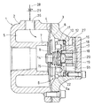
以下、この発明の第1実施形態を図面に基づいて説明する。図1に示すように、ボディ1は、円筒状のボディ本体2と、そのボディ本体2の一端にボルト止めされたヘッドカバー3とから成り、そのボディ本体2とヘッドカバー3とによってダイヤフラム4の外周部が挾持されている。ボディ1の内部空間は、上記ダイヤフラム4の張設によって給気チャンバ5と排気チャンバ6とに仕切られ、前記給気チャンバ5内にエア噴射筒7が設けられている。
Hereinafter, a first embodiment of the present invention will be described with reference to the drawings. As shown in FIG. 1, the body 1 includes a cylindrical body
ダイヤフラム4は、給気チャンバ5と排気チャンバ6を連通する小孔8が設けられている。ダイヤフラム4は排気チャンバ6内に組込まれたスプリング9の押圧により給気チャンバ5側に弾性変形して、エア噴射筒7のエア入口を閉鎖している。排気チャンバ6の内周には段部10が形成され、その段部10によって排気チャンバ6の内周にねじ係合された弁プレート11が支持されている。この弁プレート11の取付けによって排気チャンバ6は第1室6aと第2室6bとに仕切られている。
The diaphragm 4 is provided with a
前記段部10と弁プレート11の対向面間には弾性シール12が組込まれ、この弾性シール12は段部10と弁プレート11の対向面に弾性接触して、その対向面間をシールしている。弁プレート11は永久磁石が吸着可能な磁性体から成っている。この弁プレート11には第1室6aと第2室6bを連通する弁孔14が形成されている。また、弁プレート11には第1室6aに対向する端面に放射状の溝15が形成されている。
An
弁プレート11の第2室6bに対する対向面には、弁孔14を中心とする円形の凹部16が設けられ、その凹部16内にガイド筒17の先端部が嵌合されている。ガイド筒17は弁プレート11の締付けにより、先端面が凹部16の端面に衝合されていると共に、後端面が第2室6bの端面に衝合されている。ガイド筒17は両端部に通気孔18を有し、内部には弁孔14を開閉する弁体19が摺動自在に組込まれている。弁体19の弁プレート11と対向する先端面には永久磁石20が埋設され、その永久磁石20の弁プレート11に対する吸着によって弁体19は閉鎖状態に保持されている。
A
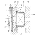
図2に示すように、弁プレート11の前記ガイド筒17の先端面が衝合された凹部16端面には環状のシール溝21が形成され、そのシール溝21に環状のシール部材22が組込まれている。シール部材22は凹部16の端面とガイド筒17の先端面に密着して、弁プレート11とガイド筒17の対向面間をシールしている。
As shown in FIG. 2, an
シール部材22の内周面には環状のシールリップ23が形成され、そのシールリップ23は弁体19が閉鎖位置に保持された状態で、その弁体19の先端部外周に形成されたテーパ面24と弾性接触して、第1室6a内に圧縮エアが流入した際、その圧縮エアが弁プレート11と弁体19の対向面間から第2室6bに漏洩するのを防止している。
An
ガイド筒17の先端部内周には環状突出部25が形成され、その環状突出部25はシールリップ23がガイド筒17内に向けて弾性変形して、弁体19のテーパ面24とガイド筒17の先端部内周面間に形成される空間に噛み込むのを防止している。図1に示すように、ボディ1には、給気チャンバ5に連通する給気口26と、第2室6bに連通する排気口27とが形成され、給気口26に接続された給気通路28に可変絞り29が取付けられている。
An
実施の形態で示すエアパルサは上記の構造から成り、給気口26に対する圧縮エアの供給停止状態において、弁体19は弁プレート11と永久磁石20の吸着によって閉鎖状態に保持されている。また、ダイヤフラム4はエア噴射筒7のエア入口を閉じている。給気通路28から給気口26に圧縮エアを供給すると、その圧縮エアは給気チャンバ5内に流入すると共に、給気チャンバ5からダイヤフラム4の小孔8を通って排気チャンバ6の第1室6a内に流入する。
The air pulser shown in the embodiment has the above-described structure, and the
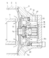
第1室6a内の圧力は圧縮エアの流入によって次第に高くなり、その圧力が永久磁石20が弁プレート11を吸着する吸着力より高くなると、弁体19が後退して弁孔14を開放する。上記弁孔14の開放によって第1室6a内の圧縮エアは弁孔14から第2室6b内に流入し、排気口27から外部に排気される。その排気によって排気チャンバ6内の圧力が低下し、給気チャンバ5と排気チャンバ6の圧力差によりダイヤフラム4は図3に示すように、排気チャンバ6側に弾性変形し、エア噴射筒7のエア入口が開放する。このため、給気チャンバ5内の圧縮エアはエア噴射筒7に流入して、そのエア噴射筒7から噴射される。
The pressure in the
一方、排気チャンバ6内の圧縮エアが排気口27から排気されて、その排気チャンバ6内の圧力が低下すると、永久磁石20と弁プレート11の相互間に作用する吸着力により弁体19が前進して弁孔14を閉鎖する。その閉鎖によって給気チャンバ5内の圧縮エアはダイヤフラム4の小孔8から排気チャンバ6の第1室6a内に流入し、第1室6a内の圧力が上昇する。第1室6a内の圧力が給気チャンバ5内の圧力とほぼ等しくなると、ダイヤフラム4が給気チャンバ5側に弾性変形して、エア噴射筒7のエア入口を閉鎖し、エア噴射筒7からの圧縮エアの噴射が遮断される。
On the other hand, when the compressed air in the exhaust chamber 6 is exhausted from the
弁体19は第1室6a内の圧力が永久磁石20の吸着力より高くなると弁孔14を開放し、排気チャンバ6内の圧縮エアが排気口27から排気されて排気チャンバ6内の圧力が低下すると弁孔14を閉鎖する。一方、ダイヤフラム4は排気チャンバ6内の圧力が低下するとエア噴射筒7のエア入口を開放し、弁体19が閉鎖して第1室6a内の圧力が給気チャンバ5内の圧力とほぼ等しくなると上記エア入口を閉鎖するため、エア噴射筒7からパルスエアを間歇的に噴射することができる。このため、電磁弁を用いることなくエアパルサを形成することができる。
When the pressure in the
ここで、給気通路28に設けられた可変絞り29の操作によって給気口26への圧縮エアの供給量を調整することにより、エア噴射筒7から噴射されるパルスエアの間隔を調整することができる。
Here, by adjusting the amount of compressed air supplied to the
上記のようなエアパルサにおいて、弁体19が弁孔14を閉鎖する状態で、第1室6a内の高圧エアが弁プレート11と弁体19の対向部間から第2室6bに漏洩すると、その漏洩量が多い場合は第1室6a内の圧力を上昇させることができず、弁体19を後退させることができないためにパルスエアを噴射させることができなくなる。一方、第1室6a内の圧縮エアの漏洩量が微量な場合には、第1室6a内の圧力が永久磁石20の吸着力より高くなるまでに時間を要し、パルスエアの噴射間隔が長くなる。
In the air pulser as described above, when the high pressure air in the
実施の形態では、弁プレート11とガイド筒17の対向面間にシール部材22を組込み、そのシール部材22の内周に弁体19の先端部外周に形成されたテーパ面24に弾性接触する環状のシールリップ23を設けているため、弁体19の閉鎖状態でシールリップ23が弁体19のテーパ面24に弾性接触すると共に、第1室6a内の圧力が高くなると、テーパ面24に対するシールリップ23の接触圧がさらに増大することになる。
In the embodiment, a
このため、弁プレート11と弁体19の対向面間を確実にシールすることができ、上記対向面間から第2室6bへの高圧エアの漏れを確実に防止することができるので、パルスエアを所定の間隔で確実に噴射させることができる。
For this reason, the space between the opposed surfaces of the
また、ガイド筒17の先端部内周に環状突出部25を設けたことにより、第1室6a内の圧力上昇によってシールリップ23の内周部がガイド筒17内に向けて変形して、弁体19のテーパ面24とガイド筒17の先端部内周面間に噛み込むのを防止することができる。したがって、弁体19の後退動が阻害されることもなく、第1室6a内の圧力上昇によって弁体19をスムーズに後退させることができ、エアパルサを高精度に作動させることができる。
Further, since the
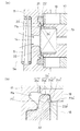
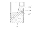
図4、図5に第2実施形態のエアパルサの要部断面図を示す。この実施形態では弁プレート11とガイド筒17、弁体19の対向面間にシール部材22を設け、このシール部材22に設けたシールリップ23’の形状を第1実施形態のシールリップ23から少し変形させ、テーパ面24を異径段状部24’に形成した点が第1実施形態と異なるが、その他の主要構成部は第1実施形態と同様であり、同じ全体構成は図示省略し、要部断面図において同じ機能構成部材には第1実施形態と同じ符号を付して説明を省略する。
4 and 5 are cross-sectional views of the main part of the air pulser according to the second embodiment. In this embodiment, a
以下では、上記第1実施形態と異なる要部を中心に説明する。図4に示すように、弁プレート11のガイド筒17の先端面に対向する部位に形成された環状のシール溝21には環状のシール部材22が組込まれているが、このシール部材22のシールリップ23’は断面視形状において内周端側に片面がやや傾斜した略台形状で、かつ、図5に示すように、自然状態では弁体19に対向する部位に半円弧状の曲面をなす凸部(突出部)23p’が形成されている。
Below, it demonstrates focusing on the principal part different from the said 1st Embodiment. As shown in FIG. 4, an
シール部材22がシール溝21に組込まれた状態でガイド筒17の先端面に密着し、弁プレート11とガイド筒17の対向面間をシールしている点は、第1実施形態と同じであるが、シールリップ23’が弁体19の先端部と接触する部位はテーパ面24に代えて異径段状部24’として形成されている。この異径段状部24’は、図4の(b)図に示すように、弁体19のテーパ面24c’、24c’の間に弁体19の径より所定寸法小径の異径部24a’を所定長さに設け、その端に軸中心に対し直角な端面24b’を形成して成る。
The
そして、上記異径段状部24’の端面24b’にシールリップ23’の凸部23p’が当接し、弁体19が閉鎖位置に保持された状態で端面24b’がシールリップ23’をその凸部23p’を介して押込むことによりシールリップ23’は弾性変形し、その弾性力を反作用として弁体19に及ぼして弾性接触しており、第1室6a内に圧縮エアが流入した際、その圧縮エアが弁プレート11と弁体19の対向面間から第2室6bに漏洩するのを防止している。
Then, the projecting
なお、シールリップ23’の軸方向への押込移動を妨げないようにするため弁プレート11のシール溝21より内径位置に環状の逃し溝11aが設けられている。又、上記異径部24a’はシールリップ23’の外周との間にわずかな隙間が残る寸法の径としている。さらに、端面24b’は軸中心と直角な面としたが、凸部23p’が弾性接触し得る範囲でやや傾斜した面としてもよい。又、符号23a’はシールリップ23’のガイド筒17の端面と接触する側の端面を示す。
An
上記の構成とした第2実施形態のエアパルサの基本作用は、第1実施形態と同様であり重複説明は省略する。この実施形態では、異径段状部24’にシールリップ23’の凸部23p’を弾性接触させてシール機能を得ているため、第1実施形態のシール機構よりもさらにシール性が高くなっている。上記凸部23p’を異径段状部24’の端面で押圧して弾性接触させているため、凸部23p’の全周に亘って均等かつ大きな接触圧が得られるからである。又、シールリープ23’の内周片が激しく開閉振動しても、シールリップ23’の端面23a’をガイド筒17の端面で受けるためシールリップ23’の弾力性を長期に保持できる。
The basic operation of the air pulsar of the second embodiment having the above-described configuration is the same as that of the first embodiment, and a duplicate description is omitted. In this embodiment, since the
従って、この実施形態では弁プレート11と弁体19の対向面間においてさらに確実に高いシール機構を確保でき、上記対向面間から第2室6bへの高圧エアの漏れを確実に防止でき、パルスエアを所望のパルス間隔で確実に噴射させることができる。
Therefore, in this embodiment, a higher sealing mechanism can be ensured between the opposed surfaces of the
1 ボディ
4 ダイヤフラム
5 給気チャンバ
6 排気チャンバ
6a 第1室
6b 第2室
7 エア噴射筒
8 小孔
11 弁プレート
14 弁孔
17 ガイド筒
18 通気孔
19 弁体
20 永久磁石
21 シール溝
22 シール部材
23、23’ シールリップ
23p’ 凸部
24 テーパ面
24’ 異径段状部
24a’ 異径部
24b’ 端面
25 環状突出部
DESCRIPTION OF SYMBOLS 1 Body 4
Claims (3)
Priority Applications (1)
| Application Number | Priority Date | Filing Date | Title |
|---|---|---|---|
| JP2004374012A JP2005291493A (en) | 2004-03-11 | 2004-12-24 | Air pulser |
Applications Claiming Priority (2)
| Application Number | Priority Date | Filing Date | Title |
|---|---|---|---|
| JP2004069132 | 2004-03-11 | ||
| JP2004374012A JP2005291493A (en) | 2004-03-11 | 2004-12-24 | Air pulser |
Publications (1)
| Publication Number | Publication Date |
|---|---|
| JP2005291493A true JP2005291493A (en) | 2005-10-20 |
Family
ID=35324631
Family Applications (1)
| Application Number | Title | Priority Date | Filing Date |
|---|---|---|---|
| JP2004374012A Pending JP2005291493A (en) | 2004-03-11 | 2004-12-24 | Air pulser |
Country Status (1)
| Country | Link |
|---|---|
| JP (1) | JP2005291493A (en) |
Cited By (3)
| Publication number | Priority date | Publication date | Assignee | Title |
|---|---|---|---|---|
| JP2010076747A (en) * | 2008-08-28 | 2010-04-08 | Advics Co Ltd | Pressure regulating reservoir |
| WO2020054000A1 (en) * | 2018-09-12 | 2020-03-19 | Smc株式会社 | Compressed-fluid discharge control device |
| JPWO2020213248A1 (en) * | 2019-04-18 | 2020-10-22 |
Citations (14)
| Publication number | Priority date | Publication date | Assignee | Title |
|---|---|---|---|---|
| JPS5275837U (en) * | 1975-11-28 | 1977-06-06 | ||
| JPS56102865U (en) * | 1980-01-09 | 1981-08-12 | ||
| JPS56102864U (en) * | 1980-01-09 | 1981-08-12 | ||
| JPS58149659U (en) * | 1982-03-31 | 1983-10-07 | アイシン精機株式会社 | check valve |
| JPS58193159U (en) * | 1982-06-18 | 1983-12-22 | カヤバ工業株式会社 | Valve seat structure |
| JPS6255775U (en) * | 1985-09-26 | 1987-04-07 | ||
| JPH05180353A (en) * | 1990-12-08 | 1993-07-20 | Dieter Wildfang Gmbh | Backflow prevention device |
| JPH05330652A (en) * | 1992-05-28 | 1993-12-14 | Hitachi Plant Eng & Constr Co Ltd | Air-transporter for powder/grain |
| JPH0630735B2 (en) * | 1985-05-24 | 1994-04-27 | 日本ニユ−マチツク工業株式会社 | Air-vibrator |
| JP3046444U (en) * | 1997-08-22 | 1998-03-10 | 夢麟 程 | Fire check valve |
| JP2001141084A (en) * | 1999-11-12 | 2001-05-25 | Kazuo Moro | Small ball valve device |
| JP2001263516A (en) * | 2000-03-15 | 2001-09-26 | Iseki & Co Ltd | Relief valve |
| JP2002153775A (en) * | 2000-11-21 | 2002-05-28 | Asmo Co Ltd | Injection nozzle |
| JP2003034429A (en) * | 2001-07-23 | 2003-02-07 | Kanekita Kk | Air pulser and device using the air pulser |
-
2004
- 2004-12-24 JP JP2004374012A patent/JP2005291493A/en active Pending
Patent Citations (14)
| Publication number | Priority date | Publication date | Assignee | Title |
|---|---|---|---|---|
| JPS5275837U (en) * | 1975-11-28 | 1977-06-06 | ||
| JPS56102865U (en) * | 1980-01-09 | 1981-08-12 | ||
| JPS56102864U (en) * | 1980-01-09 | 1981-08-12 | ||
| JPS58149659U (en) * | 1982-03-31 | 1983-10-07 | アイシン精機株式会社 | check valve |
| JPS58193159U (en) * | 1982-06-18 | 1983-12-22 | カヤバ工業株式会社 | Valve seat structure |
| JPH0630735B2 (en) * | 1985-05-24 | 1994-04-27 | 日本ニユ−マチツク工業株式会社 | Air-vibrator |
| JPS6255775U (en) * | 1985-09-26 | 1987-04-07 | ||
| JPH05180353A (en) * | 1990-12-08 | 1993-07-20 | Dieter Wildfang Gmbh | Backflow prevention device |
| JPH05330652A (en) * | 1992-05-28 | 1993-12-14 | Hitachi Plant Eng & Constr Co Ltd | Air-transporter for powder/grain |
| JP3046444U (en) * | 1997-08-22 | 1998-03-10 | 夢麟 程 | Fire check valve |
| JP2001141084A (en) * | 1999-11-12 | 2001-05-25 | Kazuo Moro | Small ball valve device |
| JP2001263516A (en) * | 2000-03-15 | 2001-09-26 | Iseki & Co Ltd | Relief valve |
| JP2002153775A (en) * | 2000-11-21 | 2002-05-28 | Asmo Co Ltd | Injection nozzle |
| JP2003034429A (en) * | 2001-07-23 | 2003-02-07 | Kanekita Kk | Air pulser and device using the air pulser |
Cited By (8)
| Publication number | Priority date | Publication date | Assignee | Title |
|---|---|---|---|---|
| JP2010076747A (en) * | 2008-08-28 | 2010-04-08 | Advics Co Ltd | Pressure regulating reservoir |
| WO2020054000A1 (en) * | 2018-09-12 | 2020-03-19 | Smc株式会社 | Compressed-fluid discharge control device |
| JPWO2020054000A1 (en) * | 2018-09-12 | 2021-08-30 | Smc株式会社 | Compressible fluid discharge control device |
| JP7331330B2 (en) | 2018-09-12 | 2023-08-23 | Smc株式会社 | Compressed fluid discharge controller |
| US11964290B2 (en) | 2018-09-12 | 2024-04-23 | Smc Corporation | Compressed-fluid discharge control device |
| JPWO2020213248A1 (en) * | 2019-04-18 | 2020-10-22 | ||
| WO2020213248A1 (en) * | 2019-04-18 | 2020-10-22 | Smc株式会社 | High-pressure fluid discharge device |
| JP7537428B2 (en) | 2019-04-18 | 2024-08-21 | Smc株式会社 | High Pressure Fluid Discharger |
Similar Documents
| Publication | Publication Date | Title |
|---|---|---|
| KR100498942B1 (en) | Air pulsar and device that use the air pulsar | |
| KR102778990B1 (en) | Fluid control valve | |
| JP3422899B2 (en) | Fixture driving tool | |
| RU2014115613A (en) | MULTI-LIQUID PUMPING CONTINUOUS DEVICE, DRIVE AND EXECUTIVE SYSTEM AND METHOD | |
| JPH0198773A (en) | Valve device | |
| DK1328256T3 (en) | Valve for osmotic devices | |
| ATE327460T1 (en) | VALVE ACTUATED VIA GAS PRESSURE TANK | |
| US7647941B2 (en) | Air pulser | |
| JP2010185469A (en) | Control valve and air hammer | |
| JP4164065B2 (en) | Air pulsar | |
| CN112689714B (en) | Fluid pressure cylinder | |
| US20090312674A1 (en) | Electromagnetic valve and pneumatic massage apparatus | |
| JP2024536400A5 (en) | ||
| ATE246325T1 (en) | GAS BOTTLE VALVE | |
| US20080223458A1 (en) | Tank vent pallet | |
| EP1948484A2 (en) | Inflator manifold | |
| EP1847739A3 (en) | Improved ball valve and valve seat | |
| JP4393369B2 (en) | Pressure regulator | |
| JP4430405B2 (en) | Fluid dispenser pump | |
| JP3960604B2 (en) | Integrated high-speed valve | |
| JP2000516677A (en) | Apparatus for distributing and supplying the minimum amount of fluid | |
| JP2005180614A (en) | Valve | |
| KR100242984B1 (en) | Magnetic plunger valve | |
| EP0075275A2 (en) | Endoscope | |
| RU2646967C1 (en) | Method and valve mechanism of short-time high pressure gas supply |
Legal Events
| Date | Code | Title | Description |
|---|---|---|---|
| A621 | Written request for application examination |
Free format text: JAPANESE INTERMEDIATE CODE: A621 Effective date: 20060207 |
|
| A977 | Report on retrieval |
Free format text: JAPANESE INTERMEDIATE CODE: A971007 Effective date: 20080123 |
|
| A131 | Notification of reasons for refusal |
Free format text: JAPANESE INTERMEDIATE CODE: A131 Effective date: 20080219 |
|
| A02 | Decision of refusal |
Free format text: JAPANESE INTERMEDIATE CODE: A02 Effective date: 20080624 |