WO2020213248A1 - High-pressure fluid discharge device - Google Patents
High-pressure fluid discharge device Download PDFInfo
- Publication number
- WO2020213248A1 WO2020213248A1 PCT/JP2020/005987 JP2020005987W WO2020213248A1 WO 2020213248 A1 WO2020213248 A1 WO 2020213248A1 JP 2020005987 W JP2020005987 W JP 2020005987W WO 2020213248 A1 WO2020213248 A1 WO 2020213248A1
- Authority
- WO
- WIPO (PCT)
- Prior art keywords
- pressure fluid
- discharge device
- valve
- chamber
- fluid discharge
- Prior art date
Links
- 239000012530 fluid Substances 0.000 title claims abstract description 78
- 238000007599 discharging Methods 0.000 claims description 4
- 238000000638 solvent extraction Methods 0.000 claims description 3
- NJPPVKZQTLUDBO-UHFFFAOYSA-N novaluron Chemical compound C1=C(Cl)C(OC(F)(F)C(OC(F)(F)F)F)=CC=C1NC(=O)NC(=O)C1=C(F)C=CC=C1F NJPPVKZQTLUDBO-UHFFFAOYSA-N 0.000 description 8
- 239000003566 sealing material Substances 0.000 description 7
- 230000002093 peripheral effect Effects 0.000 description 6
- 230000007423 decrease Effects 0.000 description 2
- 230000000149 penetrating effect Effects 0.000 description 2
- 238000003754 machining Methods 0.000 description 1
- 239000000463 material Substances 0.000 description 1
- 239000002184 metal Substances 0.000 description 1
- 238000005192 partition Methods 0.000 description 1
- 238000011144 upstream manufacturing Methods 0.000 description 1
- XLYOFNOQVPJJNP-UHFFFAOYSA-N water Substances O XLYOFNOQVPJJNP-UHFFFAOYSA-N 0.000 description 1
Images


Classifications
-
- F—MECHANICAL ENGINEERING; LIGHTING; HEATING; WEAPONS; BLASTING
- F15—FLUID-PRESSURE ACTUATORS; HYDRAULICS OR PNEUMATICS IN GENERAL
- F15B—SYSTEMS ACTING BY MEANS OF FLUIDS IN GENERAL; FLUID-PRESSURE ACTUATORS, e.g. SERVOMOTORS; DETAILS OF FLUID-PRESSURE SYSTEMS, NOT OTHERWISE PROVIDED FOR
- F15B21/00—Common features of fluid actuator systems; Fluid-pressure actuator systems or details thereof, not covered by any other group of this subclass
- F15B21/12—Fluid oscillators or pulse generators
-
- B—PERFORMING OPERATIONS; TRANSPORTING
- B05—SPRAYING OR ATOMISING IN GENERAL; APPLYING FLUENT MATERIALS TO SURFACES, IN GENERAL
- B05B—SPRAYING APPARATUS; ATOMISING APPARATUS; NOZZLES
- B05B1/00—Nozzles, spray heads or other outlets, with or without auxiliary devices such as valves, heating means
- B05B1/005—Nozzles or other outlets specially adapted for discharging one or more gases
-
- B—PERFORMING OPERATIONS; TRANSPORTING
- B05—SPRAYING OR ATOMISING IN GENERAL; APPLYING FLUENT MATERIALS TO SURFACES, IN GENERAL
- B05B—SPRAYING APPARATUS; ATOMISING APPARATUS; NOZZLES
- B05B1/00—Nozzles, spray heads or other outlets, with or without auxiliary devices such as valves, heating means
- B05B1/30—Nozzles, spray heads or other outlets, with or without auxiliary devices such as valves, heating means designed to control volume of flow, e.g. with adjustable passages
- B05B1/32—Nozzles, spray heads or other outlets, with or without auxiliary devices such as valves, heating means designed to control volume of flow, e.g. with adjustable passages in which a valve member forms part of the outlet opening
-
- B—PERFORMING OPERATIONS; TRANSPORTING
- B05—SPRAYING OR ATOMISING IN GENERAL; APPLYING FLUENT MATERIALS TO SURFACES, IN GENERAL
- B05B—SPRAYING APPARATUS; ATOMISING APPARATUS; NOZZLES
- B05B12/00—Arrangements for controlling delivery; Arrangements for controlling the spray area
- B05B12/02—Arrangements for controlling delivery; Arrangements for controlling the spray area for controlling time, or sequence, of delivery
- B05B12/06—Arrangements for controlling delivery; Arrangements for controlling the spray area for controlling time, or sequence, of delivery for effecting pulsating flow
-
- B—PERFORMING OPERATIONS; TRANSPORTING
- B05—SPRAYING OR ATOMISING IN GENERAL; APPLYING FLUENT MATERIALS TO SURFACES, IN GENERAL
- B05B—SPRAYING APPARATUS; ATOMISING APPARATUS; NOZZLES
- B05B9/00—Spraying apparatus for discharge of liquids or other fluent material, without essentially mixing with gas or vapour
- B05B9/03—Spraying apparatus for discharge of liquids or other fluent material, without essentially mixing with gas or vapour characterised by means for supplying liquid or other fluent material
-
- F—MECHANICAL ENGINEERING; LIGHTING; HEATING; WEAPONS; BLASTING
- F15—FLUID-PRESSURE ACTUATORS; HYDRAULICS OR PNEUMATICS IN GENERAL
- F15B—SYSTEMS ACTING BY MEANS OF FLUIDS IN GENERAL; FLUID-PRESSURE ACTUATORS, e.g. SERVOMOTORS; DETAILS OF FLUID-PRESSURE SYSTEMS, NOT OTHERWISE PROVIDED FOR
- F15B21/00—Common features of fluid actuator systems; Fluid-pressure actuator systems or details thereof, not covered by any other group of this subclass
-
- F—MECHANICAL ENGINEERING; LIGHTING; HEATING; WEAPONS; BLASTING
- F16—ENGINEERING ELEMENTS AND UNITS; GENERAL MEASURES FOR PRODUCING AND MAINTAINING EFFECTIVE FUNCTIONING OF MACHINES OR INSTALLATIONS; THERMAL INSULATION IN GENERAL
- F16K—VALVES; TAPS; COCKS; ACTUATING-FLOATS; DEVICES FOR VENTING OR AERATING
- F16K31/00—Actuating devices; Operating means; Releasing devices
- F16K31/12—Actuating devices; Operating means; Releasing devices actuated by fluid
- F16K31/126—Actuating devices; Operating means; Releasing devices actuated by fluid the fluid acting on a diaphragm, bellows, or the like
-
- F—MECHANICAL ENGINEERING; LIGHTING; HEATING; WEAPONS; BLASTING
- F16—ENGINEERING ELEMENTS AND UNITS; GENERAL MEASURES FOR PRODUCING AND MAINTAINING EFFECTIVE FUNCTIONING OF MACHINES OR INSTALLATIONS; THERMAL INSULATION IN GENERAL
- F16K—VALVES; TAPS; COCKS; ACTUATING-FLOATS; DEVICES FOR VENTING OR AERATING
- F16K31/00—Actuating devices; Operating means; Releasing devices
- F16K31/12—Actuating devices; Operating means; Releasing devices actuated by fluid
- F16K31/36—Actuating devices; Operating means; Releasing devices actuated by fluid in which fluid from the circuit is constantly supplied to the fluid motor
- F16K31/38—Actuating devices; Operating means; Releasing devices actuated by fluid in which fluid from the circuit is constantly supplied to the fluid motor in which the fluid works directly on both sides of the fluid motor, one side being connected by means of a restricted passage and the motor being actuated by operating a discharge from that side
- F16K31/385—Actuating devices; Operating means; Releasing devices actuated by fluid in which fluid from the circuit is constantly supplied to the fluid motor in which the fluid works directly on both sides of the fluid motor, one side being connected by means of a restricted passage and the motor being actuated by operating a discharge from that side the fluid acting on a diaphragm
-
- F—MECHANICAL ENGINEERING; LIGHTING; HEATING; WEAPONS; BLASTING
- F16—ENGINEERING ELEMENTS AND UNITS; GENERAL MEASURES FOR PRODUCING AND MAINTAINING EFFECTIVE FUNCTIONING OF MACHINES OR INSTALLATIONS; THERMAL INSULATION IN GENERAL
- F16K—VALVES; TAPS; COCKS; ACTUATING-FLOATS; DEVICES FOR VENTING OR AERATING
- F16K7/00—Diaphragm valves or cut-off apparatus, e.g. with a member deformed, but not moved bodily, to close the passage ; Pinch valves
- F16K7/12—Diaphragm valves or cut-off apparatus, e.g. with a member deformed, but not moved bodily, to close the passage ; Pinch valves with flat, dished, or bowl-shaped diaphragm
- F16K7/14—Diaphragm valves or cut-off apparatus, e.g. with a member deformed, but not moved bodily, to close the passage ; Pinch valves with flat, dished, or bowl-shaped diaphragm arranged to be deformed against a flat seat
- F16K7/17—Diaphragm valves or cut-off apparatus, e.g. with a member deformed, but not moved bodily, to close the passage ; Pinch valves with flat, dished, or bowl-shaped diaphragm arranged to be deformed against a flat seat the diaphragm being actuated by fluid pressure
-
- B—PERFORMING OPERATIONS; TRANSPORTING
- B08—CLEANING
- B08B—CLEANING IN GENERAL; PREVENTION OF FOULING IN GENERAL
- B08B5/00—Cleaning by methods involving the use of air flow or gas flow
- B08B5/02—Cleaning by the force of jets, e.g. blowing-out cavities
Definitions
- the present invention relates to a high-pressure fluid discharge device that discharges high-pressure fluid.
- a device that blows a high-pressure fluid such as high-pressure air is used to remove metal chips adhering to the surface of the work and clean the surface of the work.
- Japanese Unexamined Patent Publication No. 2014-83518 describes an intermittent air blow gun used for such an application.
- this intermittent air blow gun when the operator grasps the switch lever, the on-off valve of the air ejection flow path is opened, and the air from the pressure air source is ejected from the discharge port. At the same time, a part of the air flowing through the air ejection flow path is supplied to the pilot valve, and when the pilot valve is opened, a part of the air from the pressure air source passes through the bypass flow path to the secondary side of the on-off valve. It is sent and the on-off valve is closed.
- the present invention has been made in consideration of such circumstances, and provides a high-pressure fluid discharge device capable of intermittently discharging a high-pressure fluid without direct manual work by an operator.
- the purpose is.
- the high-pressure fluid discharge device has an input port for supplying the high-pressure fluid, a tank chamber for storing the high-pressure fluid, and a discharge port for discharging the high-pressure fluid.
- This high-pressure fluid discharge device is provided with a diaphragm valve that separates the valve chamber and the pilot chamber that communicate with the tank chamber, and the pilot chamber communicates with the valve chamber via the pilot passage, and the diaphragm valve is open.
- the valve chamber communicates with the discharge port via the discharge passage.
- An open / close control valve is provided in the open passage that opens the pilot chamber to the discharge passage, and the open / close control valve operates by the pressure of the fluid supplied from the tank chamber.
- a fluid having a high peak pressure can be periodically discharged from the discharge port simply by supplying the high-pressure fluid from the input port.
- the high-pressure fluid discharge device includes a diaphragm valve for partitioning a valve chamber communicating with the tank chamber and partitioning the pilot chamber, and an on-off control valve for opening the pilot chamber to the discharge passage is supplied from the tank chamber. Since it is configured to open and close according to the pressure of, it is possible to periodically discharge a fluid having a high peak pressure simply by supplying a high-pressure fluid from the input port.
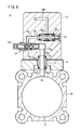
- FIG. 3 is a cross-sectional view taken along the line II-II of the high-pressure fluid discharge device of FIG.
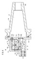
- FIG. 3 is a cross-sectional view taken along the line III-III of the high-pressure fluid discharge device of FIG.
- It is a figure which developed the high-pressure fluid discharge device of FIG. 1 into a predetermined part or a group of parts. It is a figure corresponding to FIG. 2 when the high-pressure fluid discharge device of FIG. 1 is in a different operating state. It is a figure corresponding to FIG. 3 when the high-pressure fluid discharge device of FIG. 1 is in a different operating state.
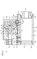
- the high-pressure fluid discharge device 10 includes a tank housing 14 having a tank chamber 12 formed therein, a diaphragm housing 18 incorporating a diaphragm valve 16, and an on-off control valve 20. It has a control housing 22 and.
- the high-pressure fluid discharge device 10 is used for removing chips and the like.
- the tank housing 14 is composed of a square cylinder-shaped cylinder tube 24, a cylindrical inlet cover 26, and a disk-shaped end cover 28.
- the inlet cover 26 is attached to one end side of the cylinder tube 24 via a C ring 30a, and includes an input port 32 penetrating in the axial direction.
- the end cover 28 is attached to the other end side of the cylinder tube 24 via the C ring 30b, and closes the other end side of the cylinder tube 24.
- a tank chamber 12 for storing high-pressure air (high-pressure fluid) supplied from the input port 32 is formed inside the cylinder tube 24, a tank chamber 12 for storing high-pressure air (high-pressure fluid) supplied from the input port 32 is formed inside the cylinder tube 24, a tank chamber 12 for storing high-pressure air (high-pressure fluid) supplied from the input port 32 is formed inside the cylinder tube 24, a tank chamber 12 for storing high-pressure air (high-pressure fluid) supplied from the input port 32 is formed inside the cylinder tube 24, a tank chamber 12 for storing high-pressure air (high-pressure fluid) supplied from the input port 32 is formed inside the cylinder tube 24, a tank chamber 12 for storing high-pressure air (high-pressure fluid) supplied from the input port 32 is formed inside the cylinder tube 24, a tank chamber 12 for storing high-pressure air (high-pressure fluid) supplied from the input port 32 is formed inside the cylinder tube 24, a tank chamber 12 for storing high-pressure air (high-pressure fluid) supplied from the input port 32 is formed inside the cylinder
- the upper side wall of the cylinder tube 24 is formed with a pedestal portion 36 projecting upward so as to extend parallel to the axis of the cylinder tube 24.
- a discharge air supply port 38 that opens at the top of the pedestal portion 36 is provided through the upper side wall of the cylinder tube 24.
- an operating air supply port 40 for supplying air toward the opening / closing control valve 20, which will be described later, is provided through the upper side wall of the cylinder tube 24, and the operating air supply port 40 is provided with a pedestal portion 36. It opens into a circular recess 36a formed at the top of the.
- a connecting plate 42 for installing the diaphragm housing 18 and the control housing 22 is provided above the cylinder tube 24.
- a concave groove 44 that matches the cross-sectional shape of the pedestal portion 36 of the cylinder tube 24 is provided on the lower surface of the connecting plate 42.
- the connecting plate 42 is fixed to the pedestal 36 by a plurality of first bolts 46 in a state where the pedestal portion 36 of the cylinder tube 24 is fitted into the concave groove 44 of the connecting plate 42.
- the connecting plate 42 is provided with a first hole 48 that penetrates in the vertical direction at a position corresponding to the discharge air supply port 38 of the tank housing 14.
- the first hole portion 48 has a lower passage forming portion 48a that matches the diameter of the discharge air supply port 38, and an upper fitting portion 48b having a diameter larger than that of the passage forming portion 48a.
- the connecting plate 42 is provided with a second hole portion 50 penetrating in the vertical direction at a position corresponding to the operating air supply port 40.
- the diaphragm housing 18 is configured by combining the first body 52 and the second body 54.
- the first body 52 and the second body 52 and the second body 52 are formed by fitting the annular convex portion 52a provided on the outer peripheral side of the right side surface of the first body 52 into the annular concave portion 54a provided on the outer peripheral side of the left side surface of the second body 54.
- the bodies 54 are butted against each other.
- the diaphragm valve 16 has a thick main body portion 16a having a cylindrical shape and a flange 16b that is thinner and more flexible than the main body portion 16a.
- the outer peripheral edge of the flange 16b is sandwiched between the first body 52 and the second body 54.
- the first body 52 is provided with an annular valve chamber 56 partitioned by the diaphragm valve 16, and the second body 54 is provided with a pilot chamber 58 partitioned by the diaphragm valve 16.
- a pilot passage 16c for communicating the pilot chamber 58 with the valve chamber 56 is provided inside the main body 16a of the diaphragm valve 16.
- One end of the pilot passage 16c opens to the side surface of the main body 16a facing the valve chamber 56, and the other end of the pilot passage 16c opens to the end surface of the main body 16a facing the pilot chamber 58.
- an annular protrusion 52b that protrudes downward is formed at a position corresponding to the discharge air supply port 38 of the tank housing 14.
- a connection passage 59 for connecting the discharge air supply port 38 to the valve chamber 56 is provided at the bottom of the first body 52 including the protrusion 52b.
- the protruding portion 52b of the first body 52 fits into the fitting portion 48b of the first hole portion 48 of the connecting plate 42.
- the discharge air supply port 38 communicates with the valve chamber 56 via the passage forming portion 48a of the first hole portion 48 of the connecting plate 42 and the connecting passage 59 of the first body 52.
- Reference numeral 34c indicates a sealing material that seals between the protruding portion 52b and the fitting portion 48b.
- the first body 52 is provided with a discharge port 60 that opens on the side surface opposite to the side surface that is abutted with the second body 54, and a discharge passage 62 that communicates with the discharge port 60 and extends to the vicinity of the diaphragm valve 16. .
- a tubular wall portion 52c that partitions the valve chamber 56 and the discharge passage 62 is provided, and the tip of the tubular wall portion 52c constitutes the valve seat 52d.
- the control housing 22 is provided with a first open passage 64a and a second open passage 64b, which are a part of the passage for opening the air in the pilot chamber 58 toward the discharge passage 62.
- One end of the first open flow path 64a opens to the side surface of the control housing 22 facing the diaphragm housing 18 and is connected to the extension passage 58a extending from the pilot chamber 58, and the other end of the first open flow path 64a is open / closed control. It is connected to the valve 20.
- reference numeral 34d is a sealing material that seals the connecting portion between the first open passage 64a and the extension passage 58a from the outside.
- the diaphragm housing 18 is provided with a third open flow path 64c and a fourth open flow path 64d, which are the rest of the flow paths for opening the air in the pilot chamber 58 toward the discharge passage 62.
- the third open flow path 64c is formed in the second body 54
- the fourth open flow path 64d is formed in the first body 52.
- One end of the fourth open passage 64d is connected to the third open passage 64c, and the other end is connected to the discharge passage 62.
- One end of the second open flow path 64b formed in the control housing 22 is connected to the on-off control valve 20, and the other end of the second open flow path 64b opens on the side surface of the control housing 22 facing the diaphragm housing 18. Then, it is connected to the third open flow path 64c formed in the second body 54.
- the on-off control valve 20 is slidable between a position where the second open flow path 64b is connected to the first open flow path 64a and a position where the second open flow path 64b is cut off from the first open flow path 64a.
- a spool 66 is provided. The spool 66 receives the urging force of the spring 68 in one direction, and also receives the urging force due to the air pressure of the second operating air flow path 70b, which will be described later, in the opposite direction.
- the first open flow path 64a is always connected to the recess 66a formed on the outer peripheral surface of the spool 66.
- the spool 66 moves to a position where the second open flow path 64b is cut off from the first open flow path 64a by the urging force of the spring 68 ( (See FIG. 3). At this time, the air in the pilot room 58 is trapped.
- the spool 66 connects the second open flow path 64b to the first open flow path 64a against the urging force of the spring 68. Move to position (see FIG. 6). At this time, the air in the pilot chamber 58 is released toward the discharge passage 62.
- the control housing 22 has an operating air flow path provided with a speed controller 74.
- the working air flow path includes a first working air flow path 70a located on the upstream side of the speed controller 74 and a second working air flow path 70b located on the downstream side of the speed controller 74.
- the first operating air flow path 70a is opened in a circular recess 22a formed at the bottom of the control housing 22, and the second operating air flow path 70b is connected to the open / close control valve 20.
- the cylindrical sleeve 72 is inserted into the second hole 50 of the connecting plate 42 and is supported between the circular recess 22a formed in the control housing 22 and the circular recess 36a formed in the pedestal 36 of the cylinder tube 24. Cylinder.
- the working air supply port 40 of the cylinder tube 24 communicates with the first working air flow path 70a via a flow path formed inside the sleeve 72.
- a sealing material 34e that abuts on the wall surface of the circular recess 22a of the control housing 22 and a sealing material 34f that abuts the wall surface of the circular recess 36a of the pedestal portion 36 of the cylinder tube 24 are mounted on the outer periphery of the sleeve 72.
- the speed controller 74 is a variable flow rate control valve that can adjust the flow rate of air flowing through the operating air flow path. By operating the knob 74a of the speed controller 74 to set the position of the needle 74b arranged inside the speed controller 74 to a desired position, the flow rate of air passing through the speed controller 74 can be adjusted. .. The flow rate of air passing through the speed controller 74 determines the rate of increase in air pressure in the second operating air flow path 70b that acts on the spool 66 of the on-off control valve 20 when the air pressure in the tank chamber 12 increases.
- the first body 52, the second body 54, and the control housing 22 are connected in series by a plurality of second bolts 76, and the first body 52 is connected to the connecting plate 42 by a plurality of third bolts 78. ..
- the diaphragm housing 18 and the control housing 22, which are composed of the first body 52 and the second body 54, are integrally connected to the connecting plate 42.
- Reference numeral 80 indicates a cover body that covers the diaphragm housing 18.
- the high-pressure fluid discharge device 10 is basically configured as described above, and its operation will be described below with reference to FIGS. 2 to 7.
- the main body 16a of the diaphragm valve 16 abuts on the valve seat 52d, and the spool 66 of the on-off control valve 20 makes the second open flow path 64b from the first open flow path 64a.
- the initial state is the state in which it is blocked. That is, the initial state is a state in which both the diaphragm valve 16 and the open / close control valve 20 are closed.
- the pressure of the air in the valve chamber 56 and the pilot chamber 58 communicating with each other through the pilot passage 16c is larger than the pressure of the air in the discharge passage 62. It is assumed that it is.
- the other part of the air in the tank chamber 12 goes to the speed controller 74 through the inside of the working air supply port 40 and the sleeve 72 and the first working air flow path 70a.
- the flow rate of air passing through the speed controller 74 that is, the flow rate of air flowing into the second operating air flow path 70b is limited to that corresponding to the position of the needle 74b of the speed controller 74. Therefore, the pressure of the air in the second operating air flow path 70b acting on the on-off control valve 20 rises at a speed commensurate with this limited flow rate.
- the spool 66 of the on-off control valve 20 moves against the urging force of the spring 68, and the second open flow path 64b is first opened. It is connected to the flow path 64a. That is, the on-off control valve 20 opens (see FIG. 6). As a result, the air in the pilot chamber 58 passes through the first open passage 64a to the fourth open passage 64d in order to reach the discharge passage 62.
- the diaphragm valve 16 opens (see FIG. 5). Then, the air supplied and stored in the tank chamber 12 through the input port 32 passes through the discharge air supply port 38, the passage forming portion 48a of the first hole portion 48 of the connecting plate 42, and the connecting passage 59 of the first body 52. After entering the valve chamber 56, it flows into the discharge passage 62 at once and is discharged to the outside from the discharge port 60.
- the pressure of the air in the tank chamber 12 decreases, and the pressure of the air in the second operating air flow path 70b acting on the spool 66 of the on-off control valve 20 also decreases. Then, when a predetermined amount of air stored in the tank chamber 12 is discharged, the pressure of the air in the second operating air flow path 70b becomes less than a predetermined value, the spool 66 moves by the urging force of the spring 68, and the second opening The flow path 64b is cut off from the first open flow path 64a. That is, the on-off control valve 20 closes.
- the air in the pilot room 58 stops opening. Further, since the air from the valve chamber 56 is filled in the pilot chamber 58 through the pilot passage 16c, the pressure of the air in the pilot chamber 58 rises. On the other hand, since the air in the valve chamber 56 and the discharge passage 62 communicating with each other is discharged to the outside from the discharge port 60, the pressure of the air in the pilot chamber 58 is higher than the pressure of the air in the valve chamber 56 and the discharge passage 62. Will also grow. As a result, the main body 16a of the diaphragm valve 16 comes into contact with the valve seat 52d, and the diaphragm valve 16 closes. Therefore, the discharge of air from the discharge port 60 is stopped, and the initial state is restored.
- FIG. 7 shows how the air pressure in the tank chamber 12 and the air pressure in the discharge port 60 change when the above series of operations are periodically repeated.
- the pressure of air in the tank chamber 12 is indicated by an alternate long and short dash line, and the pressure of air in the discharge port 60 is indicated by a solid line.
- the discharge pressure in the continuous air blow is shown by the dotted line for comparison with the case where the normal continuous air blow is performed.
- the cycle in this case depends on the air flow rate set by the speed controller 74. Specifically, if the position of the needle 74b is changed by operating the knob 74a of the speed controller 74 to reduce the flow path area around the needle 74b, the cycle becomes longer. Further, the peak pressure P2 at the discharge port 60 depends on the strength of the spring 68 of the on-off control valve 20. The stronger the spring 68 (the larger the spring constant), the larger the peak pressure P2.
- Intermittent air blow with high peak pressure P2 can effectively remove chips from the surface of the work, and consumes much less air than continuous air blow.
- air having a high peak pressure P2 can be periodically discharged from the discharge port 60 only by continuously supplying the high-pressure fluid from the input port 32.
- high-pressure air is used as the high-pressure fluid, but the fluid used is not limited to air, and any other fluid may be used as long as it is a compressible fluid.
- the speed controller is provided, but if it is not necessary to adjust the cycle, the speed controller may not be provided.
- the high-pressure fluid discharge device 90 according to the second embodiment of the present invention will be described with reference to FIGS. 8 and 9.
- the same reference reference numerals are given to the same or equivalent components as the high-pressure fluid discharge device 10 described above, and detailed description thereof will be omitted.
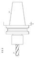
- the high-pressure fluid discharge device 90 is attached to the spindle 82 of the machining center and is used to remove chips adhering to the surface of the work.
- FIG. 9 shows a state in which the end mill (tool) 84 is mounted on the spindle 82 of the machining center via the tool holder 94.
- the high-pressure fluid discharge device 90 includes a hollow conical tool holder 94 having a tank chamber 92 formed therein, a diaphragm housing 18 incorporating a diaphragm valve 16, and an open / close control valve 20. It has a control housing 22 to be used.
- the tool holder 94 is one of a plurality of tool holders provided on the spindle 82 of the machining center.
- the high-pressure fluid discharge device 90 takes in an empty tool holder as a part of the configuration among a plurality of tool holders used for mounting a tool such as an end mill in a machining center, and takes in the internal space thereof as a tank chamber. It is used as 92.
- the tool holder 94 is provided with an input port 94a on one end side in the axial direction thereof.
- a plate-shaped cover plate 96 forming the wall surface of the tank chamber 92 together with the inner wall surface of the tool holder 94 is provided.
- a sealing material 34 g that seals the tank chamber 92 from the outside is attached to the end surface of the tool holder 94 that comes into contact with the cover plate 96.
- the cover plate 96 is provided with a discharge air supply port 96a and a working air supply port 96b so as to penetrate the wall surface thereof.
- the diaphragm housing 18 and the control housing 22 are attached to the surface of the cover plate 96 opposite to the surface with which the tool holder 94 abuts.
- an annular protruding portion 52b that protrudes to the right is formed at a position corresponding to the discharge air supply port 96a of the cover plate 96.
- the protrusion 52b fits into the cover plate 96.
- the discharge air supply port 96a communicates with the valve chamber 56 via a connection passage 59 provided on the right side surface of the first body 52 including the protrusion 52b.
- a sleeve 72 is arranged between the control housing 22 and the cover plate 96 at a position corresponding to the operating air supply port 96b of the cover plate 96.
- the working air supply port 96b of the cover plate 96 communicates with the first working air flow path 70a of the control housing 22 via the flow path formed inside the sleeve 72.
- the first body 52 is provided with a discharge port 60 that opens on the left side surface of the first body 52, and a discharge passage 62 that communicates with the discharge port 60 and extends to the vicinity of the diaphragm valve 16.
- the discharge port 60 and the discharge passage 62 extend parallel to the axial direction of the tool holder 94.
- the control housing 22 is provided with a first open flow path 64a and a second open flow path 64b as a flow path for opening the air in the pilot chamber 58 toward the discharge passage 62, and the diaphragm housing 18 is provided with a third open flow path.
- a road 64c and a fourth open flow path 64d are provided.
- the third open flow path 64c and the fourth open flow path 64d are aligned in a straight line and extend in a direction orthogonal to the discharge passage 62.
- the “open / close control valve 20 opens” ⁇ “ “Diaphragm valve 16 opens”-> "Air stored in the tank chamber 92 is discharged to the outside from the discharge port 60"-> “Open / close control valve 20 closes”-> “Diaphragm valve 16 closes”-> “From the discharge port 60”
- a series of operations of "stopping the discharge of air” is periodically repeated.
- the tool holder 94 provided on the spindle 82 of the machining center is taken in as a part of the configuration, and the internal space thereof is used as the tank chamber 92. Therefore, the tool holder 94 is attached to the machining center. Is easy, and the configuration is simplified as much as possible. Moreover, the tool holder is a standardized member, and the high-pressure fluid discharge device 90 having the same specifications can be applied to various machining centers.
- the high-pressure fluid discharge device is not limited to the above-described embodiment, and can adopt various configurations as long as the gist of the present invention is not deviated.
Landscapes
- Engineering & Computer Science (AREA)
- General Engineering & Computer Science (AREA)
- Mechanical Engineering (AREA)
- Physics & Mathematics (AREA)
- Fluid Mechanics (AREA)
- Chemical & Material Sciences (AREA)
- Analytical Chemistry (AREA)
- Fluid-Driven Valves (AREA)
- Reciprocating Pumps (AREA)
Abstract
Description
本発明の第1実施形態に係る高圧流体吐出装置10について、図1~図7を参照しながら説明する。図2および図3に示されるように、高圧流体吐出装置10は、内部にタンク室12が形成されたタンクハウジング14と、ダイヤフラム弁16を内蔵するダイヤフラムハウジング18と、開閉制御弁20を内蔵するコントロールハウジング22とを有する。高圧流体吐出装置10は、切粉の除去等のために使用される。 (First Embodiment)
The high-pressure
次に、本発明の第2実施形態に係る高圧流体吐出装置90について、図8および図9を参照しながら説明する。なお、第2実施形態に係る高圧流体吐出装置90において、上述した高圧流体吐出装置10と同一または同等の構成要素には同一の参照符号を付し、詳細な説明を省略する。 (Second Embodiment)
Next, the high-pressure
Claims (8)
- 高圧流体が供給される入力ポート(32、94a)と、前記高圧流体を貯留するタンク室(12、92)と、前記高圧流体を吐出する吐出ポート(60)とを有する高圧流体吐出装置(10、90)であって、
前記タンク室と連通する弁室(56)とパイロット室(58)とを区画するダイヤフラム弁(16)が設けられ、前記パイロット室はパイロット通路(16c)を介して前記弁室と連通しており、前記ダイヤフラム弁が開いた状態において前記弁室は吐出通路(62)を介して前記吐出ポートに連通し、前記パイロット室を前記吐出通路に開放する開放流路(64a~64d)に開閉制御弁(20)が設けられ、前記開閉制御弁は前記タンク室から供給される流体の圧力によって開閉作動する高圧流体吐出装置。 A high-pressure fluid discharge device (10) having an input port (32, 94a) to which a high-pressure fluid is supplied, a tank chamber (12, 92) for storing the high-pressure fluid, and a discharge port (60) for discharging the high-pressure fluid. , 90)
A diaphragm valve (16) for partitioning a valve chamber (56) communicating with the tank chamber and a pilot chamber (58) is provided, and the pilot chamber communicates with the valve chamber via a pilot passage (16c). With the diaphragm valve open, the valve chamber communicates with the discharge port via the discharge passage (62), and the open / close control valve is connected to the open flow path (64a to 64d) that opens the pilot chamber to the discharge passage. (20) is provided, and the on-off control valve is a high-pressure fluid discharge device that opens and closes by the pressure of the fluid supplied from the tank chamber. - 請求項1記載の高圧流体吐出装置において、
前記パイロット通路は前記ダイヤフラム弁の内部に設けられている高圧流体吐出装置。 In the high-pressure fluid discharge device according to claim 1,
The pilot passage is a high-pressure fluid discharge device provided inside the diaphragm valve. - 請求項1記載の高圧流体吐出装置において、
前記開閉制御弁を開閉作動するための流体の流路にスピードコントローラ(74)が設けられている高圧流体吐出装置。 In the high-pressure fluid discharge device according to claim 1,
A high-pressure fluid discharge device in which a speed controller (74) is provided in a fluid flow path for opening and closing the on-off control valve. - 請求項1記載の高圧流体吐出装置において、
内部に前記タンク室が形成されたタンクハウジング(14)と、前記ダイヤフラム弁を内蔵するダイヤフラムハウジング(18)と、前記開閉制御弁を内蔵するコントロールハウジング(22)とを有する高圧流体吐出装置。 In the high-pressure fluid discharge device according to claim 1,
A high-pressure fluid discharge device having a tank housing (14) in which the tank chamber is formed, a diaphragm housing (18) incorporating the diaphragm valve, and a control housing (22) incorporating the opening / closing control valve. - 請求項4記載の高圧流体吐出装置において、
前記タンクハウジングを構成するシリンダチューブ(24)の上に、前記ダイヤフラムハウジングと前記コントロールハウジングを設置するための連結プレート(42)が設けられる高圧流体吐出装置。 In the high-pressure fluid discharge device according to claim 4,
A high-pressure fluid discharge device in which a connecting plate (42) for installing the diaphragm housing and the control housing is provided on a cylinder tube (24) constituting the tank housing. - 請求項1記載の高圧流体吐出装置において、
内部に前記タンク室が形成されたツールホルダ(94)と、前記ダイヤフラム弁を内蔵するダイヤフラムハウジングと、前記開閉制御弁を内蔵するコントロールハウジングとを有する高圧流体吐出装置。 In the high-pressure fluid discharge device according to claim 1,
A high-pressure fluid discharge device having a tool holder (94) having a tank chamber formed therein, a diaphragm housing incorporating the diaphragm valve, and a control housing incorporating the opening / closing control valve. - 請求項6記載の高圧流体吐出装置において、
前記ツールホルダはその軸心方向一端側に入力ポート(94a)を備え、前記ツールホルダの軸心方向他端側にはカバープレート(96)が設けられ、前記ダイヤフラムハウジングおよび前記コントロールハウジングは前記カバープレートに取り付けられる高圧流体吐出装置。 In the high-pressure fluid discharge device according to claim 6,
The tool holder is provided with an input port (94a) on one end side in the axial direction thereof, a cover plate (96) is provided on the other end side in the axial direction of the tool holder, and the diaphragm housing and the control housing are covered. High pressure fluid discharge device attached to the plate. - 請求項1記載の高圧流体吐出装置において、
前記高圧流体は高圧エアである高圧流体吐出装置。 In the high-pressure fluid discharge device according to claim 1,
The high-pressure fluid is a high-pressure fluid discharge device in which high-pressure air is used.
Priority Applications (5)
| Application Number | Priority Date | Filing Date | Title |
|---|---|---|---|
| KR1020217036901A KR20210149174A (en) | 2019-04-18 | 2020-02-17 | High pressure fluid discharge device |
| EP20791581.0A EP3957402A4 (en) | 2019-04-18 | 2020-02-17 | High-pressure fluid discharge device |
| US17/603,375 US20220205467A1 (en) | 2019-04-18 | 2020-02-17 | High-pressure fluid discharge device |
| CN202080029559.0A CN113710369B (en) | 2019-04-18 | 2020-02-17 | High-pressure fluid ejection device |
| JP2021514808A JP7537428B2 (en) | 2019-04-18 | 2020-02-17 | High Pressure Fluid Discharger |
Applications Claiming Priority (4)
| Application Number | Priority Date | Filing Date | Title |
|---|---|---|---|
| JP2019079011 | 2019-04-18 | ||
| JP2019-079011 | 2019-04-18 | ||
| JP2019-198077 | 2019-10-31 | ||
| JP2019198077 | 2019-10-31 |
Publications (1)
| Publication Number | Publication Date |
|---|---|
| WO2020213248A1 true WO2020213248A1 (en) | 2020-10-22 |
Family
ID=72838189
Family Applications (1)
| Application Number | Title | Priority Date | Filing Date |
|---|---|---|---|
| PCT/JP2020/005987 WO2020213248A1 (en) | 2019-04-18 | 2020-02-17 | High-pressure fluid discharge device |
Country Status (7)
| Country | Link |
|---|---|
| US (1) | US20220205467A1 (en) |
| EP (1) | EP3957402A4 (en) |
| JP (1) | JP7537428B2 (en) |
| KR (1) | KR20210149174A (en) |
| CN (1) | CN113710369B (en) |
| TW (1) | TWI743737B (en) |
| WO (1) | WO2020213248A1 (en) |
Citations (8)
| Publication number | Priority date | Publication date | Assignee | Title |
|---|---|---|---|---|
| JPS60186875U (en) * | 1984-05-22 | 1985-12-11 | 富士化工株式会社 | electric brush |
| JPH04327083A (en) * | 1991-04-25 | 1992-11-16 | Yoshitake:Kk | Pilot type solenoid valve |
| JPH10165844A (en) * | 1996-12-12 | 1998-06-23 | Ckd Corp | Air jetting system |
| JP2003034429A (en) * | 2001-07-23 | 2003-02-07 | Kanekita Kk | Air pulser and device utilizing the same |
| JP2005291493A (en) * | 2004-03-11 | 2005-10-20 | Kanekita Kk | Air pulser |
| JP2009275747A (en) * | 2008-05-13 | 2009-11-26 | Nippon Spindle Mfg Co Ltd | Diaphragm valve and dust collector |
| JP2014083518A (en) | 2012-10-26 | 2014-05-12 | Honda Motor Co Ltd | Intermittent air blow gun |
| JP2016075377A (en) * | 2014-10-08 | 2016-05-12 | クロダニューマティクス株式会社 | Intermittent air generating device |
Family Cites Families (16)
| Publication number | Priority date | Publication date | Assignee | Title |
|---|---|---|---|---|
| GB2091451B (en) * | 1981-01-07 | 1985-04-17 | Reed Irrigation Systems | Filter backwash means |
| JPH03624Y2 (en) * | 1985-05-13 | 1991-01-10 | ||
| US5169117A (en) * | 1992-02-27 | 1992-12-08 | Huang Chi King | Low power type, motor-controlled magnetic valve |
| JPH08128389A (en) * | 1994-11-01 | 1996-05-21 | Hitachi Ltd | Method and apparatus for controllably driving valve and fluid supply controller |
| DE29705703U1 (en) * | 1996-06-03 | 1997-05-22 | Geberit Technik Ag, Jona | Servo-controlled water valve |
| AUPO524997A0 (en) * | 1997-02-21 | 1997-03-20 | Yoothapina Pty Ltd | Filling stop valve |
| JP3329720B2 (en) * | 1998-01-19 | 2002-09-30 | 東京エレクトロン株式会社 | Coating device |
| US6780170B2 (en) * | 2002-05-15 | 2004-08-24 | Liebel-Flarsheim Company | Hydraulic remote for a medical fluid injector |
| JP3875959B2 (en) * | 2003-03-27 | 2007-01-31 | 泰彦 渡辺 | Flow control valve |
| US7080817B2 (en) * | 2004-02-17 | 2006-07-25 | Y. Stern Engineering (1989) Ltd. | Electromagnetic valve |
| JP2008513200A (en) * | 2004-09-15 | 2008-05-01 | アクリオン テクノロジーズ インク | Apparatus and method for moving a sonic energy source, and substrate processing using the same |
| US7647941B2 (en) * | 2006-04-03 | 2010-01-19 | Masao Onoe | Air pulser |
| JP5728288B2 (en) * | 2011-04-28 | 2015-06-03 | Ckd株式会社 | Supply / exhaust adjustment device, supply / exhaust adjustment system |
| JP6047796B2 (en) * | 2015-03-03 | 2016-12-21 | 有限会社浜インターナショナル | speed controller |
| KR200480920Y1 (en) * | 2014-12-19 | 2016-07-22 | 김성곤 | Tool for releasing injector, and injection tool unit |
| KR102190802B1 (en) * | 2016-08-29 | 2020-12-14 | 가부시키가이샤 고가네이 | Switching valve and intermittent blowing gun |
-
2020
- 2020-02-17 KR KR1020217036901A patent/KR20210149174A/en not_active Application Discontinuation
- 2020-02-17 EP EP20791581.0A patent/EP3957402A4/en active Pending
- 2020-02-17 WO PCT/JP2020/005987 patent/WO2020213248A1/en active Application Filing
- 2020-02-17 CN CN202080029559.0A patent/CN113710369B/en active Active
- 2020-02-17 US US17/603,375 patent/US20220205467A1/en active Pending
- 2020-02-17 JP JP2021514808A patent/JP7537428B2/en active Active
- 2020-04-09 TW TW109111987A patent/TWI743737B/en active
Patent Citations (8)
| Publication number | Priority date | Publication date | Assignee | Title |
|---|---|---|---|---|
| JPS60186875U (en) * | 1984-05-22 | 1985-12-11 | 富士化工株式会社 | electric brush |
| JPH04327083A (en) * | 1991-04-25 | 1992-11-16 | Yoshitake:Kk | Pilot type solenoid valve |
| JPH10165844A (en) * | 1996-12-12 | 1998-06-23 | Ckd Corp | Air jetting system |
| JP2003034429A (en) * | 2001-07-23 | 2003-02-07 | Kanekita Kk | Air pulser and device utilizing the same |
| JP2005291493A (en) * | 2004-03-11 | 2005-10-20 | Kanekita Kk | Air pulser |
| JP2009275747A (en) * | 2008-05-13 | 2009-11-26 | Nippon Spindle Mfg Co Ltd | Diaphragm valve and dust collector |
| JP2014083518A (en) | 2012-10-26 | 2014-05-12 | Honda Motor Co Ltd | Intermittent air blow gun |
| JP2016075377A (en) * | 2014-10-08 | 2016-05-12 | クロダニューマティクス株式会社 | Intermittent air generating device |
Non-Patent Citations (1)
| Title |
|---|
| See also references of EP3957402A4 |
Also Published As
| Publication number | Publication date |
|---|---|
| CN113710369B (en) | 2022-11-25 |
| JPWO2020213248A1 (en) | 2020-10-22 |
| EP3957402A1 (en) | 2022-02-23 |
| US20220205467A1 (en) | 2022-06-30 |
| KR20210149174A (en) | 2021-12-08 |
| CN113710369A (en) | 2021-11-26 |
| JP7537428B2 (en) | 2024-08-21 |
| EP3957402A4 (en) | 2023-01-18 |
| TWI743737B (en) | 2021-10-21 |
| TW202042912A (en) | 2020-12-01 |
Similar Documents
| Publication | Publication Date | Title |
|---|---|---|
| US5441171A (en) | Air cannon for removing cakes of flowable material and clearing clogged areas of flowable material | |
| JP2012008795A (en) | Pressure reduction device | |
| EP4027024A1 (en) | Flow rate controller and drive device equipped with same | |
| WO2018043032A1 (en) | Switching valve and intermittent air blower gun | |
| WO2020213248A1 (en) | High-pressure fluid discharge device | |
| KR102363630B1 (en) | Compressed fluid discharge control device | |
| JP2014138977A (en) | Tool holder, tool device having tool holder, and machining tool | |
| WO2021065090A1 (en) | High-pressure fluid discharge device | |
| WO2000062973A1 (en) | Coolant feeding device of machine tool | |
| US9908073B2 (en) | Filter regulator | |
| KR102508110B1 (en) | Compressed fluid discharge control device | |
| WO2000066321A1 (en) | Coolant feeding device of machine tool | |
| CN215141145U (en) | Nozzle head and nozzle | |
| JP6578230B2 (en) | Compressed air discharge device | |
| JP3764334B2 (en) | Flow rate switching valve | |
| JP2018194158A (en) | Material discharge device and valve member | |
| JP6870495B2 (en) | Pneumatic tool with air duster | |
| JP4162627B2 (en) | Semi-dry processing equipment | |
| JP2016151308A (en) | On-off valve | |
| JP2605802Y2 (en) | speed controller | |
| JP2020133669A (en) | Flow control valve | |
| JP2011036787A (en) | Automatic spray gun for spraying multiple kinds of coating materials | |
| KR20190128527A (en) | Dispensing Valve Emission Controllers | |
| JP2005329484A (en) | Machining device | |
| JP2005329483A (en) | Semi-dry machining device |
Legal Events
| Date | Code | Title | Description |
|---|---|---|---|
| 121 | Ep: the epo has been informed by wipo that ep was designated in this application |
Ref document number: 20791581 Country of ref document: EP Kind code of ref document: A1 |
|
| ENP | Entry into the national phase |
Ref document number: 2021514808 Country of ref document: JP Kind code of ref document: A |
|
| NENP | Non-entry into the national phase |
Ref country code: DE |
|
| ENP | Entry into the national phase |
Ref document number: 20217036901 Country of ref document: KR Kind code of ref document: A |
|
| WWE | Wipo information: entry into national phase |
Ref document number: 2020791581 Country of ref document: EP |
|
| ENP | Entry into the national phase |
Ref document number: 2020791581 Country of ref document: EP Effective date: 20211118 |