JP2005291413A - Vibration damping device - Google Patents
Vibration damping device Download PDFInfo
- Publication number
- JP2005291413A JP2005291413A JP2004108686A JP2004108686A JP2005291413A JP 2005291413 A JP2005291413 A JP 2005291413A JP 2004108686 A JP2004108686 A JP 2004108686A JP 2004108686 A JP2004108686 A JP 2004108686A JP 2005291413 A JP2005291413 A JP 2005291413A
- Authority
- JP
- Japan
- Prior art keywords
- damping
- vibration
- air spring
- damping force
- orifice
- Prior art date
- Legal status (The legal status is an assumption and is not a legal conclusion. Google has not performed a legal analysis and makes no representation as to the accuracy of the status listed.)
- Pending
Links
Images


Landscapes
- Exposure And Positioning Against Photoresist Photosensitive Materials (AREA)
- Vibration Prevention Devices (AREA)
- Electron Beam Exposure (AREA)
- Exposure Of Semiconductors, Excluding Electron Or Ion Beam Exposure (AREA)
Abstract
【課題】 安価で、取り扱いが容易で、除振性能と制振性能を併せ持つ除振制振装置を提供することを課題とする。
【解決手段】
試料室(機器搭載台)5と空気ばね3とからなる系の振動に、第1減衰力と、該第1減衰力より大きな第2減衰力とのうちの一方の減衰力を選択的に加えることが可能な減衰手段(エアシリンダ11、ゴムダンパ15)と、除振を行う場合には減衰手段の第1減衰力を試料室5と空気ばね3とからなる系に加え、制振を行う場合には減衰手段の第2減衰力を試料室5と空気ばねとからなる系に加える制御手段とを有する。
【選択図】 図1PROBLEM TO BE SOLVED: To provide an anti-vibration damping device that is inexpensive, easy to handle, and has both anti-vibration performance and damping performance.
[Solution]
One of a first damping force and a second damping force larger than the first damping force is selectively applied to the vibration of the system composed of the sample chamber (equipment mounting base) 5 and the air spring 3. A damping means (air cylinder 11 and rubber damper 15) that can be used, and in the case of vibration isolation, the first damping force of the damping means is applied to the system consisting of the sample chamber 5 and the air spring 3 for vibration damping. Has a control means for applying the second damping force of the damping means to the system comprising the sample chamber 5 and the air spring.
[Selection] Figure 1
Description
本発明は、移動するステージを有する機器搭載台がベースに対して空気ばねを介して支持される放射線ビーム装置に設けられる制振除振装置に関する。 The present invention relates to a vibration damping and vibration damping device provided in a radiation beam device in which a device mounting base having a moving stage is supported by an air spring with respect to a base.
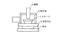
放射線ビーム装置、例えば、ウエハ観察用走査型電子顕微鏡は、図5に示すように、架台(ベース)1上に空気ばね3を介して試料室(機器搭載台)5が設けられる。試料室5内には、試料が設けられ、移動するステージ7が配置され、試料室5上には、内部に電子銃、集束レンズ、対物レンズ等が設けられ、ステージ7上の試料に対して電子線(放射線ビーム)を照射する鏡筒9が設けられる。 In a radiation beam apparatus, for example, a scanning electron microscope for wafer observation, as shown in FIG. 5, a sample chamber (equipment mounting base) 5 is provided on a base (base) 1 via an air spring 3. A sample 7 is provided in the sample chamber 5 and a moving stage 7 is disposed. An electron gun, a focusing lens, an objective lens, and the like are provided in the sample chamber 5. A lens barrel 9 for irradiating an electron beam (radiation beam) is provided.
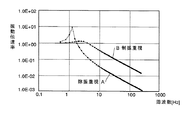
一般に、空気ばね3は、図6のA(除振重視)に示すような伝達特性が得られるように設計されている。この場合、空気ばね3の(固有振動数×√2)より高い周波数では、振動が減衰する。すなわち、床からの振動の侵入を抑えることができる。但し、空気ばねの固有振動数と同じ周波数の振動が床にある場合は共振現象を起こし、試料室5が大きく振動してしまう。 In general, the air spring 3 is designed so as to obtain a transmission characteristic as shown in A of FIG. 6 (emphasis on vibration isolation). In this case, the vibration is attenuated at a frequency higher than (natural frequency × √2) of the air spring 3. That is, the invasion of vibration from the floor can be suppressed. However, when the vibration having the same frequency as the natural frequency of the air spring is present on the floor, a resonance phenomenon occurs and the sample chamber 5 vibrates greatly.
また、試料室5に外力が加わった場合、例えば、試料室5のステージ7を移動させた場合でも、試料室5が空気ばね3の固有振動数で揺れてしまう。試料室を揺れにくくする、又は揺れてもすぐに振動が収まるようにするには、図6のB(制振重視)のような特性にすればよい。しかし、この場合、共振倍率が減るものの、空気ばね3の(固有振動数×√2)より高い周波数では減衰率が小さくなってしまい、高倍率・高分解能で観察する際に、床からの振動の影響を受け、高倍率の性能を維持できない問題点がある。 Further, when an external force is applied to the sample chamber 5, for example, even when the stage 7 of the sample chamber 5 is moved, the sample chamber 5 is shaken at the natural frequency of the air spring 3. In order to make the sample chamber difficult to shake, or to make the vibrations settle immediately even if the sample chamber is shaken, a characteristic such as B (emphasis on vibration suppression) in FIG. 6 may be used. However, in this case, although the resonance magnification is reduced, the damping rate becomes small at a frequency higher than (natural frequency × √2) of the air spring 3, and vibration from the floor is observed when observing with high magnification and high resolution. There is a problem that high magnification performance cannot be maintained.
空気ばねの減衰を調整する手法は様々なものがある。しかし、除振と、制振との相反する機能を両立できないので、いずれかを重視した調整がなされている。このような除振装置をパッシブ(Passive)型除振装置という。 There are various methods for adjusting the damping of the air spring. However, since the functions of anti-vibration and anti-vibration are not compatible, adjustments are made with emphasis on one of them. Such a vibration isolator is called a passive vibration isolator.
このようなパッシブ型除振装置に対して、アクティブ(Active)制御型の除振装置が提案されている。アクティブ型除振装置の一例として、空気ばね上の振動を加速度計等で測定し、その振動を打ち消すようにリニアモータ等のアクチュエータで力を加えるフィード・バック制御を用いると共に、ステージの移動情報等により予め振動が発生しないようにリニアモータ等のアクチュエータで力を加えるフィード・フォワード制御を用いるタイプがある(例えば、特許文献1参照)。
しかし、アクティブ型除振装置は、加速度計等のセンサやアクチュエータや複雑な制御回路等が必要となり、非常に高価である。また、チューニングに高い技術が必要で客先で長期間性能を維持することが難しい。更に、予測外の力が作用した場合に制御不能となり発振してしまう場合もある。 However, the active vibration isolator requires a sensor such as an accelerometer, an actuator, a complicated control circuit, and the like, and is very expensive. In addition, high technology is required for tuning, and it is difficult for customers to maintain performance for a long time. In addition, when an unexpected force is applied, control may become impossible and oscillation may occur.
本発明上記問題点に鑑みてなされたもので、その課題は、安価で、取り扱いが容易で、除振性能と制振性能を併せ持つ除振制振装置を提供することにある。 The present invention has been made in view of the above-described problems, and an object thereof is to provide a vibration damping device that is inexpensive, easy to handle, and has both vibration damping performance and vibration damping performance.
請求項1に係る発明は、移動するステージを有する機器搭載台がベースに対して空気ばねを介して支持される放射線ビーム装置に設けられる制振除振装置おいて、前記機器搭載台と前記空気ばねとからなる系の振動に、第1減衰力と、該第1減衰力より大きな第2減衰力とのうちの一方の減衰力を選択的に加えることが可能な減衰手段と、除振を行う場合には前記減衰手段の第1減衰力を前記機器搭載台と前記空気ばねとからなる系に加え、制振を行う場合には前記減衰手段の第2減衰力を前記機器搭載台と前記空気ばねとからなる系に加える制御手段と、を有することを特徴とする制振除振装置である。 According to a first aspect of the present invention, there is provided a vibration damping device provided in a radiation beam device in which a device mounting table having a moving stage is supported by an air spring with respect to a base, the device mounting table and the air A damping means capable of selectively applying one of a first damping force and a second damping force larger than the first damping force to the vibration of a system comprising a spring; When performing damping, the first damping force of the damping means is applied to the system comprising the device mounting base and the air spring, and when damping is performed, the second damping force of the damping means is applied to the device mounting base and the device. And a control means for adding to the system comprising an air spring.
制御手段は、除振を行う場合には前記減衰手段の第1減衰力を前記機器搭載台と前記空気ばねとからなる系に加え、制振を行う場合には前記減衰手段の第2減衰力を前記機器搭載台と前記空気ばねとからなる系に加える。 The control means applies the first damping force of the damping means to the system composed of the device mounting base and the air spring when performing vibration isolation, and the second damping force of the damping means when performing vibration damping. Is added to the system consisting of the device mounting base and the air spring.
請求項2に係る発明は、前記減衰手段は、前記ベースに設けられ、前記機器搭載台に離反/当接可能な弾性体と、該弾性体を駆動する駆動部と、を有し、前記弾性体が前記機器搭載台に離反した状態では前記第1減衰力、前記弾性体が前記機器搭載台に当接した状態では前記第2減衰力であることを特徴とする請求項1記載の制振除振装置である。 According to a second aspect of the present invention, the damping means includes an elastic body that is provided on the base and can be separated / contacted with the device mounting base, and a drive unit that drives the elastic body. 2. The vibration damping device according to claim 1, wherein the damping force is the first damping force when the body is separated from the device mounting base, and the second damping force is when the elastic body is in contact with the device mounting base. It is a vibration isolator.
制御手段は、除振を行う場合には減衰手段の駆動部を駆動して弾性体を機器搭載台から離反させ、制振を行う場合には減衰手段の駆動部を駆動して弾性体を機器搭載台に当接させる。 The control means drives the damping means drive unit to separate the elastic body from the device mounting base when performing vibration isolation, and drives the damping means drive unit to control the elastic body when performing vibration damping. Contact the mounting base.
具体的な構成の一例として、エア、油圧、電動シリンダと、このシリンダのスピンドルに設けられたゴム等の弾性体とからなるものある。
請求項3に係る発明は、前記減衰手段は、前記空気ばねに空気を供給する管路に設けられる第1オリフィスと、前記空気ばねに空気を供給する管路に設けられ、前記第1オリフィスのオリフィス径より径が小さな第2オリフィスと、前記第1オリフィス、前記第2オリフィスを切り替える駆動部とを有し、前記第1オリフィスを前記管路に設けた状態では前記第1減衰力、前記第2オリフィスを前記管路に設けた状態では前記第2減衰力であることを特徴とする請求項1記載の制振除振装置である。
As an example of a specific configuration, there is an air, hydraulic, electric cylinder, and an elastic body such as rubber provided on a spindle of the cylinder.
According to a third aspect of the present invention, the damping means is provided in a first orifice provided in a pipe that supplies air to the air spring, and in a pipe that supplies air to the air spring. A second orifice having a smaller diameter than the orifice diameter, the first orifice, and a drive unit for switching the second orifice, and the first damping force, the first orifice when the first orifice is provided in the pipe line 2. The vibration damping device according to claim 1, wherein the second damping force is obtained when two orifices are provided in the pipe line.
制御手段は、除振を行う場合には減衰手段の駆動部を駆動して第1オリフィスを管路に設け、制振を行う場合には減衰手段の駆動部を駆動して第2オリフィスを管路に設ける。
具体的な構成の一例としては、第1オリフィスが設けられた第1管路と、第2オリフィスが設けられた第2管路と、第1管路、第2管路を切り替える電磁切り替え弁とがある。
The control means drives the damping means driving section to provide the first orifice in the pipe line when performing vibration isolation, and drives the damping means driving section to connect the second orifice when performing vibration damping. Provide on the road.
As an example of a specific configuration, a first pipeline provided with a first orifice, a second pipeline provided with a second orifice, an electromagnetic switching valve for switching between the first pipeline and the second pipeline, There is.
請求項1から5に係る発明によれば、前記機器搭載台と前記空気ばねとからなる系の振動に、第1減衰力と、該第1減衰力より大きな第2減衰力とのうちの一方の減衰力を選択的に加えることが可能な減衰手段と、除振を行う場合には前記減衰手段の第1減衰力を前記機器搭載台と前記空気ばねとからなる系に加え、制振を行う場合には前記減衰手段の第2減衰力を前記機器搭載台と前記空気ばねとからなる系に加える制御手段とを有している。 According to the first to fifth aspects of the present invention, one of a first damping force and a second damping force larger than the first damping force is applied to the vibration of the system including the device mounting base and the air spring. A damping means that can selectively apply a damping force of the above, and when vibration isolation is performed, a first damping force of the damping means is applied to a system composed of the device mounting base and the air spring to suppress vibration. When performing, it has a control means which applies the 2nd damping force of the said damping means to the system which consists of the said device mounting base and the said air spring.
除振を行う場合と制振を行う場合との2つの場合に応じて、制御手段は機器搭載台と空気ばねとからなる系に加える減衰力を切り替えるだけなので、制御が容易で、チューニングも不要で、長期間性能を維持することが可能で、予測外の力が作用した場合に制御不能とならない。更に、高価なセンサや複雑な制御回路等が不要となるので、安価である。 The control means simply switches the damping force applied to the system consisting of the equipment mounting base and air spring according to the two cases of vibration isolation and vibration suppression, so control is easy and tuning is not required Therefore, it is possible to maintain the performance for a long period of time, and it is not impossible to control when an unexpected force is applied. Furthermore, since an expensive sensor, a complicated control circuit, etc. are unnecessary, it is inexpensive.
請求項2に係る発明によれば、弾性体の材質、形状を変えることで、所望の第2減衰力を得ることができる。
請求項3に係る発明によれば、第1オリフィス、第2オリフィスのオリフィス径を変えることで、所望の第1減衰力、第2減衰力を得ることができる。
According to the invention which concerns on Claim 2, desired 2nd damping force can be obtained by changing the material and shape of an elastic body.
According to the third aspect of the invention, desired first damping force and second damping force can be obtained by changing the orifice diameters of the first orifice and the second orifice.
(第1形態例)
第1形態例をウエハ観察用走査型電子顕微鏡に適用した場合の発明部分の構成図である図1、図1の電気的構成を説明する図2を用いて説明する。
(First embodiment)
The first embodiment will be described with reference to FIG. 1 which is a configuration diagram of an invention portion when applied to a scanning electron microscope for wafer observation, and FIG. 2 for explaining the electrical configuration of FIG.
図1において、機器搭載台としての試料室5は空気ばね3を介してベースとしての架台1に支持されている。本形態例の試料室5と空気ばね3とからなる系の振動に、減衰力を与える減衰手段は、架台1に設けられ、駆動部としてのエアシリンダ11と、このエアシリンダ11のスピンドル13の先端に設けられた弾性体としてのゴムダンパ15とからなっている。エアシリンダ11を駆動することにより、ゴムダンパ15は試料室5に離反(図において2点鎖線で示す)/当接(図において実線で示す)可能となっている。すなわち、ゴムダンパ15が試料室5から離反した状態では第1減衰力を、ゴムダンパ15が試料室5に当接した状態では第2減衰力を試料室5と空気ばね3とからなる系の振動に与えるようになっている。 In FIG. 1, a sample chamber 5 as an equipment mounting base is supported by a base 1 as a base via an air spring 3. Damping means for imparting damping force to the vibration of the system composed of the sample chamber 5 and the air spring 3 according to this embodiment is provided in the gantry 1 and includes an air cylinder 11 as a drive unit and a spindle 13 of the air cylinder 11. It consists of a rubber damper 15 as an elastic body provided at the tip. By driving the air cylinder 11, the rubber damper 15 can be separated from the sample chamber 5 (indicated by a two-dot chain line in the drawing) / contacted (indicated by a solid line in the drawing). That is, when the rubber damper 15 is separated from the sample chamber 5, the first damping force is applied to the vibration of the system including the sample chamber 5 and the air spring 3 when the rubber damper 15 is in contact with the sample chamber 5. To give.
19はエアシリンダ11を駆動する圧縮エアのエアシリンダ11に対する導入方向を切り替える電磁切り替え弁である。
次に、図2を用いて図1の電気的構成を説明する。21は操作者が選択的に押す除振スイッチ23、制振スイッチ25からの信号を取り込んで、電磁切り替え弁19を駆動する制御手段である。
Next, the electrical configuration of FIG. 1 will be described with reference to FIG.
ここで、上記構成の作動を説明する。高倍率・高分解能で観察する場合(除振性能を重視する場合)には、操作者は、除振スイッチ23を押す。制御手段21は除振スイッチ23が押されると、電磁切り替え弁19を駆動して、エアシリンダ11のスピンドル13を引っ込める。すなわち、ゴムダンパ15を試料室5から離反させる。すると、空気ばね3は図6のA除振重視の特性となる。
Here, the operation of the above configuration will be described. When observing with high magnification and high resolution (when importance is attached to vibration isolation performance), the operator presses the
一方、試料室5のステージを移動させる場合(制振性能を重視する場合)には、操作者は制振スイッチ25を押す。制御手段21は制振スイッチ25が押されると、電磁切り替え弁19を駆動して、エアシリンダ11のスピンドル13を出す。すなわち、ゴムダンパ15を試料室5に当接させる。すると、空気ばね3は図6のB制振重視の特性となる。
On the other hand, when the stage of the sample chamber 5 is moved (when the damping performance is important), the operator presses the
このような構成によれば、以下のような効果を得ることができる。
(1)除振を行う場合と制振を行う場合との2つの場合に応じて、制御手段21は試料室5と空気ばねとからなる系に加える減衰力を切り替えるだけなので、制御が容易で、チューニングも不要で、長期間性能を維持することが可能で、予測外の力が作用した場合に制御不能とならない。更に、高価なセンサや複雑な制御回路等が不要となるので、安価である。
(2)ゴムダンパの材質、形状を変えることで、所望の第2減衰力、すなわち、制振性能を得ることができる。
(第2形態例)
第2形態例をウエハ観察用走査型電子顕微鏡に適用した場合の発明部分の構成図である図3、図3の電気的構成を説明する図4を用いて説明する。尚、本形態例と第1形態例との相違点は、本形態例ではエアシリンダやゴムダンパがない点である。
According to such a configuration, the following effects can be obtained.
(1) Since the control means 21 only switches the damping force applied to the system composed of the sample chamber 5 and the air spring in accordance with two cases of vibration isolation and vibration suppression, control is easy. Tuning is not required, performance can be maintained for a long time, and control is not lost when an unexpected force is applied. Furthermore, since an expensive sensor, a complicated control circuit, etc. are unnecessary, it is inexpensive.
(2) A desired second damping force, that is, a vibration damping performance can be obtained by changing the material and shape of the rubber damper.
(Second embodiment)
The second embodiment will be described with reference to FIG. 3, which is a configuration diagram of the invention portion when applied to a scanning electron microscope for wafer observation, and FIG. 4 for explaining the electrical configuration of FIG. The difference between this embodiment and the first embodiment is that there is no air cylinder or rubber damper in this embodiment.
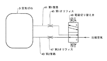
そして、本形態例の減衰手段は、図3に示すように、空気ばねに3に接続され、空気ばね3に圧縮空気を供給可能な第1管路41に設けられた第1オリフィス45と、第2管路43に設けられ、オリフィス径が第1オリフィス45の径より小さな第2オリフィス47と、第1管路41、第2管路43とを切り替える駆動部としての電磁切り替え弁49とからなっている。本形態例では、第1オリフィス45の直径を0.8mm、第2オリフィス47の直径を0.3mmとした。
As shown in FIG. 3, the damping means of the present embodiment is connected to the air spring 3, and the first orifice 45 provided in the first pipe 41 that can supply compressed air to the air spring 3, From a second orifice 47 provided in the second pipeline 43 and having an orifice diameter smaller than the diameter of the first orifice 45, and an
電磁切り替え弁49を切り替えることにより、圧縮空気は第1オリフィス45が設けられた第1管路41又は第2オリフィス47が設けられた第2管路43を介して空気ばね3に導入されるようになっている。すなわち、空気ばね3に導入される圧縮空気が第1オリフィス(第1管路41)45を通過すると第1減衰力を、第2オリフィス(第2管路43)47を通過すると第2減衰力を試料室5と空気ばね3とからなる系の振動に与えるようになっている。
By switching the
次に、図4を用いて図3の電気的構成を説明する。51は操作者が選択的に押す除振スイッチ23、制振スイッチ25からの信号を取り込んで、電磁切り替え弁49を駆動する制御手段である。
Next, the electrical configuration of FIG. 3 will be described with reference to FIG.
ここで、上記構成の作動を説明する。高倍率・高分解能で観察する場合(除振性能を重視する場合)には、操作者は、除振スイッチ23を押す。制御手段51は除振スイッチ23が押されると、電磁切り替え弁49を駆動して、空気ばね3に導入される圧縮空気が第1オリフィス(第1管路41)45を通過するようにする。すると、空気ばね3は図6のA除振重視の特性となる。
Here, the operation of the above configuration will be described. When observing with high magnification and high resolution (when importance is attached to vibration isolation performance), the operator presses the
一方、試料室のステージを移動させる場合(制振性能を重視する場合)には、操作者は制振スイッチ25を押す。制御手段51は制振スイッチ25が押されると、電磁切り替え弁49を駆動して、空気ばね3に導入される圧縮空気が第2オリフィス(第2管路43)47を通過するようにする。すると、空気ばね3は図6のB制振重視の特性となる。
On the other hand, when moving the stage of the sample chamber (when importance is attached to the vibration damping performance), the operator presses the
このような構成によれば、以下のような効果を得ることができる。
(1)除振を行う場合と制振を行う場合との2つの場合に応じて、制御手段51は試料室と空気ばねとからなる系に加える減衰力を切り替えるだけなので、制御が容易で、チューニングも不要で、長期間性能を維持することが可能で、予測外の力が作用した場合に制御不能とならない。更に、高価なセンサや複雑な制御回路等が不要となるので、安価である。
(2)第1オリフィス45、第2オリフィス47のオリフィス径を変えることで、所望の第1減衰力、第2減衰力を得ることができる。
According to such a configuration, the following effects can be obtained.
(1) Since the control means 51 only switches the damping force applied to the system consisting of the sample chamber and the air spring according to the two cases of vibration isolation and vibration suppression, control is easy. Tuning is not required, performance can be maintained for a long time, and control is not lost when an unexpected force is applied. Furthermore, since an expensive sensor, a complicated control circuit, etc. are unnecessary, it is inexpensive.
(2) By changing the orifice diameters of the first orifice 45 and the second orifice 47, desired first damping force and second damping force can be obtained.
尚、本発明は上記形態例に限定するものではない。上記形態例では、ウエハ観察用走査型電子顕微鏡に適用した場合で説明を行ったが、他の放射線ビーム装置、例えば、電子ビーム描画装置や半導体プロセス評価装置・分析装置等にも適用できる。 The present invention is not limited to the above embodiment. In the above-described embodiment, the description has been made on the case where the present invention is applied to a scanning electron microscope for wafer observation.
3 空気ばね
5 試料室
11 エアシリンダ
15 ゴムダンパ
19 電磁切り替え弁
21 制御部
3 Air Spring 5 Sample Chamber 11 Air Cylinder 15
Claims (3)
前記機器搭載台と前記空気ばねとからなる系の振動に、第1減衰力と、該第1減衰力より大きな第2減衰力とのうちの一方の減衰力を選択的に加えることが可能な減衰手段と、
除振を行う場合には前記減衰手段の第1減衰力を前記機器搭載台と前記空気ばねとからなる系に加え、制振を行う場合には前記減衰手段の第2減衰力を前記機器搭載台と前記空気ばねとからなる系に加える制御手段と、
を有することを特徴とする制振除振装置。 In a vibration damping and vibration damping device provided in a radiation beam device in which a device mounting base having a moving stage is supported via an air spring with respect to a base,
One of a first damping force and a second damping force larger than the first damping force can be selectively applied to the vibration of the system including the device mounting base and the air spring. Attenuating means;
When performing vibration isolation, the first damping force of the damping means is applied to the system composed of the device mounting base and the air spring, and when damping is performed, the second damping force of the damping means is mounted on the device. Control means applied to a system comprising a table and the air spring;
A vibration damping and vibration damping device characterized by comprising:
前記ベースに設けられ、前記機器搭載台に離反/当接可能な弾性体と、
該弾性体を駆動する駆動部と、
を有し、
前記弾性体が前記機器搭載台に離反した状態では前記第1減衰力、前記弾性体が前記機器搭載台に当接した状態では前記第2減衰力であることを特徴とする請求項1記載の制振除振装置。 The attenuation means is
An elastic body provided on the base and capable of separating / contacting with the device mounting base;
A drive unit for driving the elastic body;
Have
2. The first damping force when the elastic body is separated from the device mounting base, and the second damping force when the elastic body is in contact with the device mounting base. Vibration damping device.
前記空気ばねに空気を供給する管路に設けられる第1オリフィスと、
前記空気ばねに空気を供給する管路に設けられ、前記第1オリフィスのオリフィス径より径が小さな第2オリフィスと、
前記第1オリフィス、前記第2オリフィスを切り替える駆動部と、
を有し、
前記第1オリフィスを前記管路に設けた状態では前記第1減衰力、前記第2オリフィスを前記管路に設けた状態では前記第2減衰力であることを特徴とする請求項1記載の制振除振装置。 The attenuation means is
A first orifice provided in a conduit for supplying air to the air spring;
A second orifice provided in a conduit for supplying air to the air spring and having a diameter smaller than the orifice diameter of the first orifice;
A drive unit for switching the first orifice and the second orifice;
Have
2. The control according to claim 1, wherein the first damping force is provided when the first orifice is provided in the pipeline, and the second damping force is provided when the second orifice is provided in the pipeline. Vibration isolation device.
Priority Applications (1)
| Application Number | Priority Date | Filing Date | Title |
|---|---|---|---|
| JP2004108686A JP2005291413A (en) | 2004-04-01 | 2004-04-01 | Vibration damping device |
Applications Claiming Priority (1)
| Application Number | Priority Date | Filing Date | Title |
|---|---|---|---|
| JP2004108686A JP2005291413A (en) | 2004-04-01 | 2004-04-01 | Vibration damping device |
Publications (1)
| Publication Number | Publication Date |
|---|---|
| JP2005291413A true JP2005291413A (en) | 2005-10-20 |
Family
ID=35324563
Family Applications (1)
| Application Number | Title | Priority Date | Filing Date |
|---|---|---|---|
| JP2004108686A Pending JP2005291413A (en) | 2004-04-01 | 2004-04-01 | Vibration damping device |
Country Status (1)
| Country | Link |
|---|---|
| JP (1) | JP2005291413A (en) |
Cited By (4)
| Publication number | Priority date | Publication date | Assignee | Title |
|---|---|---|---|---|
| CN104916515A (en) * | 2014-03-13 | 2015-09-16 | 灿美工程股份有限公司 | Sample observing apparatus |
| CN108394819A (en) * | 2018-06-04 | 2018-08-14 | 江北建设有限公司 | A kind of novel building crane |
| CN108816490A (en) * | 2018-06-04 | 2018-11-16 | 江北建设有限公司 | A kind of architectural engineering construction waste crushing device |
| WO2021073653A1 (en) * | 2019-10-18 | 2021-04-22 | 安路普(北京)汽车技术有限公司 | Method and system for adjusting height and damping force |
-
2004
- 2004-04-01 JP JP2004108686A patent/JP2005291413A/en active Pending
Cited By (6)
| Publication number | Priority date | Publication date | Assignee | Title |
|---|---|---|---|---|
| CN104916515A (en) * | 2014-03-13 | 2015-09-16 | 灿美工程股份有限公司 | Sample observing apparatus |
| CN104916515B (en) * | 2014-03-13 | 2017-04-12 | 灿美工程股份有限公司 | Sample observing apparatus |
| CN108394819A (en) * | 2018-06-04 | 2018-08-14 | 江北建设有限公司 | A kind of novel building crane |
| CN108816490A (en) * | 2018-06-04 | 2018-11-16 | 江北建设有限公司 | A kind of architectural engineering construction waste crushing device |
| WO2021073653A1 (en) * | 2019-10-18 | 2021-04-22 | 安路普(北京)汽车技术有限公司 | Method and system for adjusting height and damping force |
| US11926188B2 (en) | 2019-10-18 | 2024-03-12 | Airlop (Beijing) Automotive Technology Co., Lt | Method and system for adjusting height and damping force |
Similar Documents
| Publication | Publication Date | Title |
|---|---|---|
| US20090208039A1 (en) | Hybrid actuator, loudspeaker and sound output method | |
| JP3726207B2 (en) | Active vibration isolator | |
| JP2005291413A (en) | Vibration damping device | |
| JP2012129575A (en) | Audio insulator and audio system | |
| JP2978162B1 (en) | Active vibration isolation device | |
| JP2000249185A (en) | Active vibration isolator | |
| WO2018225546A1 (en) | Charged particle beam device | |
| JP3541586B2 (en) | Vibration control mechanism for pointing control device | |
| JP3403748B2 (en) | Positioning device and table device using the same | |
| JPH02150526A (en) | Vibration isolator | |
| JP6362941B2 (en) | Charged particle beam equipment | |
| JP2000234646A (en) | Vibration control device | |
| JP3724863B2 (en) | Precision vibration isolator | |
| JP2009226967A (en) | Engine vibration damping system | |
| DE4021000A1 (en) | HI=FI loudspeaker with sprung coupling member - has mechanical oscillation element controlled by movement of electrical conductor within magnetic field | |
| US10643774B2 (en) | Vibration generation device and input device with vibration mechanism | |
| JP2008052947A (en) | Charged particle beam equipment | |
| JPH0533826A (en) | Active vibration isolation device | |
| JP2694681B2 (en) | Microscope equipment | |
| JP3292505B2 (en) | Active vibration isolator | |
| KR101766089B1 (en) | Frequency variable steering wheel damper | |
| JP3667884B2 (en) | Local analyzer | |
| JP2007080668A (en) | Sample moving device for charged particle beam equipment | |
| JP7336594B2 (en) | Charged particle beam device | |
| JP3681072B2 (en) | Active vibration isolator |
Legal Events
| Date | Code | Title | Description |
|---|---|---|---|
| A621 | Written request for application examination |
Free format text: JAPANESE INTERMEDIATE CODE: A621 Effective date: 20061130 |
|
| A977 | Report on retrieval |
Free format text: JAPANESE INTERMEDIATE CODE: A971007 Effective date: 20090318 |
|
| A131 | Notification of reasons for refusal |
Free format text: JAPANESE INTERMEDIATE CODE: A131 Effective date: 20090324 |
|
| A02 | Decision of refusal |
Free format text: JAPANESE INTERMEDIATE CODE: A02 Effective date: 20090714 |