JP2005291328A - Tool for mounting and dismounting valve - Google Patents
Tool for mounting and dismounting valve Download PDFInfo
- Publication number
- JP2005291328A JP2005291328A JP2004106061A JP2004106061A JP2005291328A JP 2005291328 A JP2005291328 A JP 2005291328A JP 2004106061 A JP2004106061 A JP 2004106061A JP 2004106061 A JP2004106061 A JP 2004106061A JP 2005291328 A JP2005291328 A JP 2005291328A
- Authority
- JP
- Japan
- Prior art keywords
- valve
- pipe
- air pipe
- air
- gas bag
- Prior art date
- Legal status (The legal status is an assumption and is not a legal conclusion. Google has not performed a legal analysis and makes no representation as to the accuracy of the status listed.)
- Pending
Links
- 238000003780 insertion Methods 0.000 claims abstract description 15
- 230000037431 insertion Effects 0.000 claims abstract description 15
- 230000000903 blocking effect Effects 0.000 claims description 14
- 238000004891 communication Methods 0.000 claims description 7
- 239000003566 sealing material Substances 0.000 claims description 2
- 239000012530 fluid Substances 0.000 abstract description 17
- 230000002265 prevention Effects 0.000 abstract description 7
- 238000009792 diffusion process Methods 0.000 description 13
- 238000000034 method Methods 0.000 description 5
- 230000000694 effects Effects 0.000 description 4
- 238000012423 maintenance Methods 0.000 description 3
- 239000000463 material Substances 0.000 description 3
- 238000010926 purge Methods 0.000 description 3
- 238000007789 sealing Methods 0.000 description 3
- 239000013013 elastic material Substances 0.000 description 2
- 239000002184 metal Substances 0.000 description 2
- 238000012856 packing Methods 0.000 description 2
- 125000002066 L-histidyl group Chemical group [H]N1C([H])=NC(C([H])([H])[C@](C(=O)[*])([H])N([H])[H])=C1[H] 0.000 description 1
- 238000007796 conventional method Methods 0.000 description 1
- 230000008878 coupling Effects 0.000 description 1
- 238000010168 coupling process Methods 0.000 description 1
- 238000005859 coupling reaction Methods 0.000 description 1
- 230000007423 decrease Effects 0.000 description 1
- 238000009434 installation Methods 0.000 description 1
- 239000007788 liquid Substances 0.000 description 1
- 230000002093 peripheral effect Effects 0.000 description 1
- 239000011347 resin Substances 0.000 description 1
- 229920005989 resin Polymers 0.000 description 1
- XLYOFNOQVPJJNP-UHFFFAOYSA-N water Substances O XLYOFNOQVPJJNP-UHFFFAOYSA-N 0.000 description 1
Images
Landscapes
- Pipe Accessories (AREA)
- Details Of Valves (AREA)
Abstract
Description
本発明は、弁孔を一対の接続口に亘って一連の直線状に連通するように設けてある弁箱に、前記弁孔の途中を開閉自在な弁体を設けてある弁を、配管内に流体が通流している活管状態で、前記一対の接続口の一方を接続してある前記配管の端部から脱着するために使用する弁脱着用治具に関する。 The present invention provides a valve box in which a valve hole is provided so as to communicate with a series of straight lines across a pair of connection ports, and a valve provided with a valve body that can be opened and closed halfway through the valve hole. The present invention relates to a valve detachment jig used for detaching from an end portion of the pipe to which one of the pair of connection ports is connected in a live pipe state in which a fluid flows through the pipe.
例えば、都市ガス供給用埋設配管には、配管工事などの際に使用するガスパージ用の放散管と、その放散管の端部を開閉自在なプラグ弁などの開閉弁とを接続してあり、開閉弁は、必要に応じて開閉操作できるように、マンホール内に設けてあるが、開閉弁のメンテナンスや交換などの際には、その開閉弁を放散管から脱着する必要がある。
従来、このような場合には、ユーザーへのガス供給に支障を来さないように配管内に流体が通流している活管状態で、開閉弁を放散管の端部から脱着しても、管内流体の外部への漏れ出しを防止できるように、弁脱着用治具としての所謂ノーブローバッグを使用して、そのノーブローバッグで開閉弁を配管の端部と共に囲んでおき、作業者がそのノーブローバッグの内側に手や腕を差し込んで脱着作業を行っている(慣用技術であり、先行技術文献情報を開示できない)。
For example, a buried pipe for city gas supply is connected to a diffusion pipe for gas purging used for piping work, etc., and an opening / closing valve such as a plug valve that can open and close the end of the diffusion pipe. The valve is provided in the manhole so that it can be opened and closed as necessary. However, when the on-off valve is maintained or replaced, it is necessary to remove the on-off valve from the diffusion tube.
Conventionally, in such a case, even if the open / close valve is detached from the end of the diffusion pipe in a live pipe state in which the fluid flows in the pipe so as not to hinder the gas supply to the user, In order to prevent leakage of fluid in the pipe to the outside, a so-called no blow bag is used as a valve detachment jig, and the no blow bag surrounds the open / close valve together with the end of the pipe so that the operator can Detachment work is performed by inserting a hand or arm into the inside of the no-blow bag (this is a conventional technique and information on prior art documents cannot be disclosed).
このため、ノーブローバッグの装着が不完全であったり、不慣れな作業者が脱着作業を行った場合は、管内流体が外部に漏れ出すおそれがあるので、脱着作業に熟練を要する欠点があり、また、作業者がノーブローバッグの内側に手や腕を差し込んで脱着作業を行うために、大型の開閉弁になるほど、作業性が低下する欠点もある。
本発明は上記実情に鑑みてなされたものであって、放散管などの配管の端部に接続されている開閉弁などが、弁孔を一対の接続口に亘って一連の直線状に連通するように設けてある弁箱に、その弁孔の途中を開閉自在な弁体を設けてある弁であり、その一対の接続口の一方を配管の端部に接続してある点に着目して、配管内に流体が通流している活管状態でも、特別な熟練を要することなく、管内流体が外部に漏れ出さないように弁を配管の端部から脱着でき、しかも、大型の弁でも、作業性が低下しないように脱着できる弁脱着用治具を提供することを目的とする。
For this reason, when the installation of the no-blow bag is incomplete or when an unfamiliar worker performs the detachment work, there is a possibility that the fluid in the pipe may leak outside, so there is a drawback that requires skill in the detachment work, Moreover, since the operator inserts his / her hands and arms into the inside of the no-blow bag and performs the detaching operation, there is a drawback that the workability decreases as the opening / closing valve becomes larger.
The present invention has been made in view of the above circumstances, and an on-off valve or the like connected to an end of a pipe such as a diffusion tube communicates a valve hole in a series of straight lines across a pair of connection ports. Pay attention to the point that the valve box is provided with a valve body that can be opened and closed in the middle of the valve hole, and one of the pair of connection ports is connected to the end of the pipe Even in a live pipe state where fluid is flowing through the pipe, the valve can be detached from the end of the pipe so that the pipe fluid does not leak outside without requiring special skill. An object of the present invention is to provide a valve attachment / detachment jig that can be attached / detached so that workability does not deteriorate.
本発明の第1特徴構成は、弁孔を一対の接続口に亘って一連の直線状に連通するように設けてある弁箱に、前記弁孔の途中を開閉自在な弁体を設けてある弁を、配管内に流体が通流している活管状態で、前記一対の接続口の一方を接続してある前記配管の端部から脱着するために使用する弁脱着用治具であって、配管内を遮断可能なガスバッグとそのガスバッグに接続してある空気管とを、前記弁体の開弁操作で前記一対の接続口に亘って連通させた前記弁孔を通して、配管内に挿脱自在に設けるとともに、前記弁の他方の接続口に対して、前記ガスバッグと前記空気管とを挿抜自在な状態で、気密に接続可能な弁接続部を一端側に備え、かつ、前記空気管を気密に挿通自在な空気管挿通部を他端側に備えていて、前記空気管を接続してあるガスバッグを収容自在な筒体と、前記空気管と空気ポンプとを着脱自在に接続可能な空気管接続部とを設け、前記ガスバッグ内の加圧空気の洩れ出しを阻止可能な阻止手段を阻止解除操作可能に前記空気管に設けて、その空気管の前記空気管接続部側を、前記筒体の前記空気管挿通部と前記弁接続部、及び、前記配管の端部から外した弁の弁孔から出し入れ自在に設けてある点にある。 In the first characteristic configuration of the present invention, a valve body that is provided so as to communicate with a series of straight lines over a pair of connection ports is provided with a valve body that can be opened and closed halfway through the valve hole. A valve detachment jig used for detaching the valve from an end of the pipe to which one of the pair of connection ports is connected in a live pipe state where a fluid is flowing in the pipe, A gas bag capable of shutting off the inside of the pipe and an air pipe connected to the gas bag are inserted into the pipe through the valve hole which is communicated over the pair of connection ports by opening the valve body. A valve connection portion that can be connected in an airtight manner in a state in which the gas bag and the air pipe can be freely inserted into and removed from the other connection port of the valve, and is provided on one end side, and the air An air tube insertion portion is provided on the other end side through which the tube can be inserted in an airtight manner and is connected to the air tube. Provided with a cylinder that can accommodate a spbag, and an air pipe connection part that allows the air pipe and the air pump to be detachably connected, and prevents blocking means that can prevent leakage of pressurized air in the gas bag. The air pipe is provided in the air pipe so as to be able to be released, and the air pipe connecting portion side of the air pipe is removed from the air pipe insertion portion and the valve connecting portion of the cylindrical body and the end of the pipe. It is in a point that it can be freely inserted and removed from the valve hole.
〔作用及び効果〕
配管内を遮断可能なガスバッグとそのガスバッグに接続してある空気管とを、弁体の開弁操作で一対の接続口に亘って連通させた弁孔を通して、配管内に挿脱自在に設けるとともに、弁の他方の接続口に対して、ガスバッグと空気管とを挿抜自在な状態で、気密に接続可能な弁接続部を一端側に備え、かつ、空気管を気密に挿通自在な空気管挿通部を他端側に備えていて、空気管を接続してあるガスバッグを収容自在な筒体を設けてあるので、配管内に流体が通流している活管状態でも、管内流体が外部に漏れ出さないように、弁体の開弁操作で弁孔を一対の接続口に亘って一連の直線状に連通させて、その弁孔を通して、ガスバッグとそのガスバッグに接続してある空気管を配管内に押し込めるとともに、弁を配管の端部から外しても、管内流体が外部に漏れ出さないように、その配管内に押し込んだガスバッグで配管内を遮断しておくことができる。
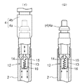
つまり、図7(イ)に例示するように、ガスバッグ1と空気管2とを、弁体Hの開弁操作で一対の接続口E1,E2に亘って連通させた弁孔Fを通して、配管B1内に挿脱自在に設けて、予め、ガスバッグ1を筒体7の内部に収容するとともに、そのガスバッグ1に接続してある空気管2を筒体7の他端側に備えた空気管挿通部6に気密に挿通し、筒体7の一端側に備えた弁接続部5を、筒体7に収容してあるガスバッグ1と空気管2とを挿抜自在な状態で、弁Cの他方の接続口E2に対して気密に接続しておくことができるので、図7(ロ)に例示するように、活管状態で、弁体Hの開弁操作で弁孔Fを一連の直線状に連通させても、管内流体が外部に漏れ出すことがなく、ガスバッグ1と空気管2とを弁孔Fを通して配管B1内に押し込めるとともに、その押し込んだガスバッグ1を、空気管2を通して供給した空気で膨らまして、弁Cを配管B1の端部から外しても管内流体が外部に漏れ出さないように、配管B1内を遮断しておくことができる。
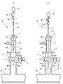
また、空気管と空気ポンプとを着脱自在に接続可能な空気管接続部を設け、ガスバッグ内の加圧空気の洩れ出しを阻止可能な阻止手段を阻止解除操作可能に空気管に設けてあるので、図8(ハ)に例示するように、空気管2と空気ポンプ3との接続を外しても、ガスバッグ1が収縮しないようにガスバッグ1内の加圧空気の洩れ出しを阻止して、配管内を遮断しておくことができるとともに、阻止解除操作によりガスバッグ1を収縮させて、弁孔Fを通して、配管B1内から筒体7内に回収することもできる。
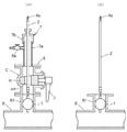
更に、その空気管の空気管接続部側を、筒体の空気管挿通部と弁接続部、及び、配管の端部から外した弁の弁孔から出し入れ自在に設けてあるので、図8(ニ)に例示するように、ガスバッグ1で配管B1内を遮断したままの状態で、空気管2の空気管接続部4側を、筒体7の空気管挿通部6と弁接続部5、及び、弁孔Fから出し入れして、配管B1の端部から外した弁Cをメンテナンスできるように取り出したり、図9(ホ)に例示するように、メンテナンスを終えた弁Cや交換用の弁Cを接続することもできる。
尚、メンテナンスを終えた弁や交換用の弁を接続する際は、上述の手順とは逆の手順によって配管の端部に接続することができる。
その上、弁の接続口に筒体の弁接続部を接続すれば良いので、大型の弁でも、管内流体が外部に漏れ出さないように、配管の端部から容易に脱着できる。
従って、配管内に流体が通流している活管状態でも、特別な熟練を要することなく、管内流体が外部に漏れ出さないように弁を配管の端部から脱着でき、しかも、大型の弁でも、作業性が低下しないように脱着できる。
[Action and effect]
A gas bag that can shut off the inside of the pipe and an air pipe connected to the gas bag can be inserted into and removed from the pipe through a valve hole that communicates over a pair of connection ports by opening the valve body. In addition to providing a valve connection portion that can be connected in an airtight manner to the other connection port of the valve in a state where the gas bag and the air tube can be inserted and removed, the air tube can be inserted in an airtight manner. Since the air tube insertion portion is provided on the other end side and the cylinder that can accommodate the gas bag to which the air tube is connected is provided, the fluid in the tube can be used even in a live tube state in which the fluid flows in the piping. The valve hole is connected to the gas bag and the gas bag through the valve hole by making the valve hole communicate with a series of straight lines by opening the valve body so that the valve does not leak to the outside. Even if a certain air pipe is pushed into the pipe and the valve is removed from the end of the pipe, As fluid does not leak to the outside, it may have been cut off the pipe in the gas bag is pushed into the pipe.
That is, as illustrated in FIG. 7A, piping is performed through a valve hole F in which the
In addition, an air pipe connection part is provided that allows the air pipe and the air pump to be detachably connected, and a blocking means that can prevent leakage of pressurized air in the gas bag is provided on the air pipe so that the blocking operation can be performed. Therefore, as illustrated in FIG. 8C, even if the connection between the
Furthermore, since the air pipe connection part side of the air pipe is provided so as to be freely inserted and removed from the air pipe insertion part and valve connection part of the cylinder and the valve hole of the valve removed from the end of the pipe, FIG. As illustrated in (d), the air
When connecting a valve for which maintenance has been completed or a replacement valve, it can be connected to the end of the pipe by a procedure reverse to the above-described procedure.
In addition, since it is only necessary to connect the valve connection portion of the cylindrical body to the connection port of the valve, even a large valve can be easily detached from the end portion of the pipe so that the fluid in the pipe does not leak outside.
Therefore, even in a live pipe state where fluid flows through the pipe, the valve can be detached from the end of the pipe so that the pipe fluid does not leak to the outside without requiring special skill. It can be removed so that workability does not deteriorate.
本発明の第2特徴構成は、前記弁接続部を、前記弁の他方の接続口に設けてある接続用フランジにボルト連結可能な治具側フランジを設けて構成し、前記接続用フランジと前記治具側フランジとを突き合わせて連結する連結用ボルトの前記治具側フランジに対する装着位置を調節自在に設けてある点にある。 According to a second characteristic configuration of the present invention, the valve connection portion is configured by providing a jig-side flange that can be bolted to a connection flange provided at the other connection port of the valve, and the connection flange and the The mounting position of the connecting bolt for butting and connecting the jig side flange with respect to the jig side flange is adjustable.
〔作用及び効果〕
弁接続部を、弁の他方の接続口に設けてある接続用フランジにボルト連結可能な治具側フランジを設けて構成し、接続用フランジと治具側フランジとを突き合わせて連結する連結用ボルトの治具側フランジに対する装着位置を調節自在に設けてあるので、弁に設けてある接続用フランジにおける連結用ボルトの装着位置が、弁の種類や大きさ毎に異なっているような場合でも、それらの接続用フランジ毎に対応する治具側フランジを設けてある筒体を使用することなく、接続用フランジにおける連結用ボルトの装着位置に応じて、治具側フランジにおける連結用ボルトの装着位置を調節することにより、その接続用フランジと治具側フランジとを突き合わせてボルト連結して、弁接続部を弁の他方の接続口に対して気密に接続できる。
[Action and effect]
A connecting bolt for connecting the connecting flange and the jig side flange together by connecting the connecting flange and the jig side flange to the connecting flange provided at the other connecting port of the valve. Since the mounting position on the jig side flange is adjustable, even if the mounting position of the connecting bolt on the connecting flange provided on the valve differs depending on the type and size of the valve, The mounting position of the connecting bolt on the jig side flange according to the mounting position of the connecting bolt on the connecting flange, without using a cylinder with a corresponding jig side flange for each connecting flange. By adjusting this, the connecting flange and the jig side flange are abutted and bolted together, and the valve connecting portion can be airtightly connected to the other connection port of the valve.
本発明の第3特徴構成は、前記治具側フランジの接続面に、前記筒体周りで環状の環状溝を形成し、その環状溝に弾性シール材を接続面から突出するように装着してある点にある。 According to a third characteristic configuration of the present invention, an annular groove is formed around the cylindrical body on the connection surface of the jig side flange, and an elastic seal material is attached to the annular groove so as to protrude from the connection surface. There is a point.
〔作用及び効果〕
弁接続部を構成する治具側フランジの接続面に、筒体周りで環状の環状溝を形成し、その環状溝に弾性シール材を接続面から突出するように装着してあるので、弁の接続用フランジ側に装着してあるシール用パッキンなどを特に使用することなく、接続用フランジと治具側フランジとを突き合わせて気密に接続できる。
[Action and effect]
An annular groove is formed around the cylinder on the connection surface of the jig side flange that constitutes the valve connection portion, and an elastic sealing material is mounted in the annular groove so as to protrude from the connection surface. The connection flange and the jig-side flange can be brought into contact with each other without using a seal packing attached to the connection flange side.
本発明の第4特徴構成は、前記筒体に、その筒体内部に連通する連通管を開閉自在に接続してある点にある。 A fourth characteristic configuration of the present invention lies in that a communication pipe communicating with the inside of the cylinder is connected to the cylinder so as to be freely opened and closed.
〔作用及び効果〕
弁接続部を介して弁に気密に接続する筒体に、その筒体内部に連通する連通管を開閉自在に接続してあるので、図9(ホ)に例示するように、メンテナンスを終えた弁Cや交換用の弁Cを開弁状態で配管B1の端部に接続して筒体7を配管B1に連通させるとともに、連通管8を開いて、配管B1の端部に残留している空気などを管外に放出することができる。
[Action and effect]
Since the connecting pipe communicating with the inside of the cylinder is connected to the cylinder that is airtightly connected to the valve via the valve connection portion, the maintenance is completed as illustrated in FIG. The valve C and the replacement valve C are connected to the end of the pipe B1 in an open state so that the
以下に本発明の実施の形態を図面に基づいて説明する。
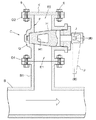
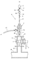
図1は、図2に示す本発明による弁脱着用治具Aを使用して、都市ガス供給用配管B内にガス(流体)が通流している活管状態で、その配管Bの端部から脱着するプラグ弁(弁の一例)Cを示し、このプラグ弁Cは、配管Bの一部を構成しているガスパージ用の放散管B1を開閉できるように、その端部に接続してある。
Embodiments of the present invention will be described below with reference to the drawings.
FIG. 1 shows an end of a pipe B in a live pipe state in which a gas (fluid) is flowing into a city gas supply pipe B using the valve demounting jig A according to the present invention shown in FIG. 1 shows a plug valve (an example of a valve) C that is attached to and detached from the pipe, and this plug valve C is connected to an end portion thereof so that a gas purging diffusion pipe B1 constituting a part of the pipe B can be opened and closed. .
前記プラグ弁Cは、一対の接続用フランジD1,D2を備えた接続口E1,E2に亘って横断面形状が円形の弁孔Fを一連の直線状に連通するように設けてある弁箱Gに、弁孔Fの途中を開閉自在な円錐台形状の弁体Hを回動自在に設けて、操作レバーJによる弁体Hの回動操作で開閉操作自在に設けてあり、弁体Hには横断面形状が略台形の連通孔H1を形成してある。 The plug valve C is a valve box G provided so that a valve hole F having a circular cross section communicates with a series of straight lines over connection ports E1 and E2 provided with a pair of connection flanges D1 and D2. In addition, a truncated cone-shaped valve body H that can be opened and closed in the middle of the valve hole F is provided so as to be rotatable, and can be opened and closed by turning the valve body H by an operation lever J. Has a communication hole H1 having a substantially trapezoidal cross-sectional shape.
そして、プラグ弁Cの一方の接続口(以下、第1接続口という)E1に設けてある接続用フランジ(以下、第1接続用フランジという)D1を、放散管B1の端部に着脱自在にパッキンを挟んでフランジ接続すると共に、他方の接続口(以下、第2接続口という)E2に設けてある接続用フランジ(以下、第2接続用フランジという)D2に塞ぎ板Kをパッキンを挟んで着脱自在にボルト連結して、必要に応じて、塞ぎ板Kを第2接続用フランジD2から外してプラグ弁Cを開閉操作できるように、マンホールなどに設けてある。 A connection flange (hereinafter referred to as a first connection flange) D1 provided at one connection port (hereinafter referred to as a first connection port) E1 of the plug valve C is detachably attached to an end portion of the diffusion tube B1. The flange is connected by sandwiching the packing, and the closing plate K is sandwiched by the sealing flange K2 on the connection flange (hereinafter referred to as the second connection flange) D2 provided in the other connection port (hereinafter referred to as the second connection port) E2. It is provided in a manhole or the like so that it can be detachably bolted and the plug valve C can be opened and closed by removing the closing plate K from the second connection flange D2 as necessary.
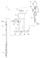
図2は、本発明による弁脱着用治具Aを示し、放散管B1内を遮断可能なガスバッグ1とそのガスバッグ1に接続してある金属製の硬質空気管2とを、弁体Hの開弁操作で一対の接続口E1,E2に亘って連通させたプラグ弁Cの弁孔Fを通して、放散管B1内に挿脱自在に設け、コック3aと圧力計3bとねじ式のキャップ3cとを備えた空気供給管3dに接続してある手動空気ポンプ3と、空気管2とを着脱自在に接続可能な空気管接続部4を設けてある。
FIG. 2 shows a valve attaching / detaching jig A according to the present invention. A
前記空気管接続部4は、雄型プラグ4aを雌型ソケット4bに押し込むワンタッチ操作で着脱自在に接続されるいわゆるワンタッチジョイントで構成してあり、最大外径が雌型ソケット4bよりも小さい雄型プラグ4aを空気管2側に固定し、雌型ソケット4bを空気ポンプ3の空気供給管3d側に固定してある。
The air
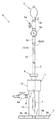
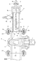
また、図3,図4にも示すように、プラグ弁Cの第2接続口E2に対して、塞ぎ板Kに代えて気密に接続可能な弁接続部5を一端側に備え、かつ、空気管2を気密に挿通自在な空気管挿通部6を他端側に備えていて、空気管2に接続してあるガスバッグ1を収容自在な円筒体7を設けてあり、この円筒体7は、透明樹脂製筒部材7aの一端側に、空気管挿通部6を設けてある金属製キャップ7bをねじ込み固定して構成してあり、筒部材7aには、円筒体7の内部に連通する連通管8をコック8aで開閉自在に接続してある。
As shown in FIGS. 3 and 4, the second connection port E2 of the plug valve C is provided with a
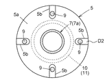
前記弁接続部5は、プラグ弁Cの第2接続用フランジD2にボルト連結可能な治具側フランジ5aを筒部材7aの他端側にねじ込んで構成してあり、図5にも示すように、治具側フランジ5aにボルト装着用の径方向に長い切欠き部5bの複数(本実施形態では4個)をフランジ周方向に等間隔を隔てて形成して、第2接続用フランジD2と治具側フランジ5aとを突き合わせて連結する連結用ボルト9の治具側フランジ5aに対する装着位置をフランジ径方向に調節自在に設けてある。
The
また、治具側フランジ5aの接続面5cに、円筒体7周りで環状の環状溝10を形成して、その環状溝10に弾性材で形成したシール用Oリング(弾性シール材の一例)11を接続面5cから突出するように装着して、第2接続用フランジD2と治具側フランジ5aとを突き合わせて連結用ボルト9で連結することにより、ガスバッグ1と空気管2とを挿抜自在な状態で、第2接続口E2に対して気密に接続できるように構成してある。
Further, an
前記空気管挿通部6は、空気管2を挿通自在に形成した貫通孔6aの内周面に弾性材で形成したシール用Oリング6bを装着して、空気管2を気密に挿通自在に設けるとともに、Oリング6bを弾性的に拡径変形させることにより、空気管2の空気管接続部側を構成している雄型プラグ4aを挿抜自在に設けてある。
The air
また、空気管2に、ガスバッグ1内の加圧空気の洩れ出しを阻止可能な阻止手段12を阻止解除操作可能に設けて、ガスバッグ1を膨らました状態で、雄型プラグ4aを雌型ソケット4bから外しても、そのガスバッグ1が収縮しないように構成してある。
Further, the
前記阻止手段12は、図6に示すように、通過する空気流量が設定流量を超えると閉弁するように設けてある過流防止弁を、空気管2の端部内側に同芯状に装着して、その空気管2の端部にねじ込み固定してある雄型ソケット4aで抜け止めするように設けてあり、この過流防止弁12は、外径が空気管2の内径と略同径の円筒部材13の内側に弁座14を設けると共に、その弁座14よりも空気流入方向の下手側に、弁座14から間隔を隔てて球状弁体15をコイルバネ16で支持して構成してある。
As shown in FIG. 6, the blocking means 12 is provided with an overflow prevention valve concentrically provided on the inner side of the end of the
そして、雄型プラグ4aを雌型ソケット4bに押し込んで、空気ポンプ3で空気管2を通してガスバッグ1に加圧空気を供給するときは、図6(イ)に示すように、弁座14と球状弁体15との間を通して加圧空気が空気管2に流入し、雄型プラグ4aを雌型ソケット4bから外したときに、過流防止弁12を通して加圧空気が流出するに伴って、設定流量を超えて流出すると、図6(ロ)に示すように、弁座14側に生じた負圧で球状弁体15がコイルバネ16の付勢力に抗して弁座14に引き寄せられて閉弁し、空気管2内の空気圧でその閉弁状態が維持されるように構成してある。
When the
前記弁脱着用治具Aの使用方法を説明する。
空気ポンプ3から外してある空気管2を、円筒体7に治具側フランジ5a側から入り込ませて、雄型プラグ4aごと空気管挿通部6に挿通し、図7(イ)に示すように、収縮させてあるガスバッグ1を円筒体7内に収容するとともに、雄型プラグ4aを雌型ソケット4bに押し込んで空気管2を空気ポンプ3に接続しておき、治具側フランジ5aをプラグ弁Cの第2接続用フランジD2に連結ボルト9で気密に連結する。
A method of using the valve detachment jig A will be described.
The
次に、図7(ロ)に示すように、プラグ弁Cを開弁操作して、空気管2でガスバッグ1を放散管B1内に押し込み、空気ポンプ3でガスバッグ1を膨らませて、放散管B1内を気密に遮断する。
Next, as shown in FIG. 7 (b), the plug valve C is opened to push the
次に、図8(ハ)に示すように、雄型プラグ4aを雌型ソケット4bから外して、図8(ニ)に示すように、ガスバッグ1で放散管B1内を気密に遮断したまま、円筒体7をプラグ弁Cから外して空気管2から引き出すとともに、プラグ弁Cを放散管B1の端部から外して空空気管2から引き出す。
Next, as shown in FIG. 8 (c), the
そして、メンテナンスを終えたプラグ弁Cや交換用のプラグ弁Cを、放散管B1の端部に接続するときは、上述の手順とは逆の手順で開弁状態で接続して、空気ポンプ3でガスバッグ1に加圧空気を送り込む操作で球状弁体15を弁座14から離して過流防止弁12を開弁した後、ガスバッグ1内の空気が過流防止弁12を通して設定流量を超えない流量で外部に放出されるようにキャップ3cを緩めてガスバッグ1を縮径させ、図9(ホ)に示すように、そのガスバッグ1を空気管2で円筒体7内に引きすとともに、コック8aの開弁操作で連通管8を開いて、放散管B1の端部に残留している空気などを、連通管8に接続してあるパージ用ホース17を通して外部に放出し、その後、プラグ弁Cを閉弁して、円筒体7をガスバッグ1や空気管2ごと撤去する。
When the plug valve C or the replacement plug valve C that has been maintained is connected to the end portion of the diffusion pipe B1, the air pump 3 is connected in the valve open state by a procedure reverse to the above procedure. After the
〔その他の実施形態〕
1.本発明による弁脱着用治具を使用して脱着する弁は、弁孔を一対の接続口に亘って一連の直線状に連通するように設けてある弁箱に、前記弁孔の途中を開閉自在な弁体を設けてある弁であれば、仕切弁やボール弁などであっても良く、その形式は特に限定されない。
2.本発明による弁脱着用治具を使用して脱着する弁は、配管に対してねじ込んで接続する形式の接続部を各接続口に対応して備えた弁であっても良い。
3.本発明による弁脱着用治具を使用して脱着する弁は、水道用配管などの液体用配管に接続してある弁であっても良い。
4.本発明による弁脱着用治具は、横断面形状が角形の筒体を設けてあっても良い。
5.本発明による弁脱着用治具は、筒体の一端側に、弁の接続部にねじ込んで気密に接続可能な弁接続部を設けてあっても良い。
6.本発明による弁脱着用治具は、筒体の一端側に、弁の接続部にワイヤーやチェーンなどで固縛して気密に接続可能な弁接続部を設けてあっても良い。
7.本発明による弁脱着用治具は、筒体の他端側に、空気管の空気管接続部側を、空気ポンプに接続した状態で、出し入れ自在に設けあっても良い。
8.本発明による弁脱着用治具は、筒体と空気管挿通部と弁接続部とを周方向で複数に分解可能に設けて、これらの筒体と空気管挿通部と弁接続部とを周方向で複数に分解することにより、空気管の空気管接続部側を、筒体の空気管挿通部と弁接続部とから出し入れ自在に設けあっても良い。
[Other Embodiments]
1. The valve to be attached and detached using the valve attaching / detaching jig according to the present invention opens and closes the middle of the valve hole in a valve box provided so that the valve hole communicates with a series of straight lines across a pair of connection ports. As long as the valve is provided with a flexible valve body, it may be a gate valve or a ball valve, and its type is not particularly limited.
2. The valve to be attached / detached using the valve attaching / detaching jig according to the present invention may be a valve provided with a connection portion of a type to be screwed into and connected to the piping corresponding to each connection port.
3. The valve attached and detached using the valve attaching / detaching jig according to the present invention may be a valve connected to a liquid pipe such as a water pipe.
4). The valve demounting jig according to the present invention may be provided with a cylindrical body having a square cross section.
5). The valve attachment / detachment jig according to the present invention may be provided with a valve connection portion that can be screwed into the connection portion of the valve and connected in an airtight manner on one end side of the cylindrical body.
6). The valve attaching / detaching jig according to the present invention may be provided with a valve connecting portion that can be airtightly connected to a connecting portion of the valve with a wire or a chain on one end side of the cylinder.
7). The valve attaching / detaching jig according to the present invention may be provided on the other end side of the cylinder body so that the air pipe connecting portion side of the air pipe is connected to an air pump.
8). The valve detachment jig according to the present invention is provided with a cylindrical body, an air pipe insertion portion, and a valve connection portion that can be disassembled into a plurality of parts in the circumferential direction. By disassembling the air pipe into a plurality of directions, the air pipe connecting part side of the air pipe may be provided so as to be freely inserted and removed from the air pipe insertion part and the valve connecting part of the cylindrical body.
1 ガスバッグ
2 空気管
3 空気ポンプ
4 空気管接続部
5 弁接続部
5a 治具側フランジ
5c 接続面
6 空気管挿通部
7 筒体
8 連通管
9 連結用ボルト
10 環状溝
11 弾性シール材
12 阻止手段
B1 配管
C 弁
D2 接続用フランジ
E1 接続口
E2 接続口
F 弁孔
G 弁箱
H 弁体
DESCRIPTION OF
Claims (4)
配管内を遮断可能なガスバッグとそのガスバッグに接続してある空気管とを、前記弁体の開弁操作で前記一対の接続口に亘って連通させた前記弁孔を通して、配管内に挿脱自在に設けるとともに、
前記弁の他方の接続口に対して、前記ガスバッグと前記空気管とを挿抜自在な状態で、気密に接続可能な弁接続部を一端側に備え、かつ、前記空気管を気密に挿通自在な空気管挿通部を他端側に備えていて、前記空気管を接続してあるガスバッグを収容自在な筒体と、前記空気管と空気ポンプとを着脱自在に接続可能な空気管接続部とを設け、
前記ガスバッグ内の加圧空気の洩れ出しを阻止可能な阻止手段を阻止解除操作可能に前記空気管に設けて、その空気管の前記空気管接続部側を、前記筒体の前記空気管挿通部と前記弁接続部、及び、前記配管の端部から外した弁の弁孔から出し入れ自在に設けてある弁脱着用治具。 A valve is provided with a valve body that can be opened and closed in the middle of the valve hole in a valve box provided so that the valve hole communicates with a series of straight lines across a pair of connection ports. A valve detachment jig used for detaching from the end of the pipe to which one of the pair of connection ports is connected in a flowing live pipe state,
A gas bag capable of shutting off the inside of the pipe and an air pipe connected to the gas bag are inserted into the pipe through the valve hole which is communicated over the pair of connection ports by opening the valve body. While providing it freely,
A valve connection part that can be connected in an airtight manner with the gas bag and the air pipe being detachable with respect to the other connection port of the valve is provided on one end side, and the air pipe can be inserted in an airtight manner. An air pipe connecting portion having a simple air pipe insertion portion on the other end side and capable of accommodating a gas bag to which the air pipe is connected, and the air pipe and the air pump being detachable. And
A blocking means capable of blocking leakage of pressurized air in the gas bag is provided in the air pipe so as to be capable of blocking and releasing, and the air pipe connecting portion side of the air pipe is inserted into the air pipe of the cylindrical body. And a valve attachment / detachment jig provided so as to be freely inserted and removed from a valve hole of a valve removed from an end portion of the valve and the valve connecting portion and the pipe.
前記接続用フランジと前記治具側フランジとを突き合わせて連結する連結用ボルトの前記治具側フランジに対する装着位置を調節自在に設けてある請求項1記載の弁脱着用治具。 The valve connection portion is configured by providing a jig-side flange that can be bolted to a connection flange provided at the other connection port of the valve,
The valve mounting / demounting jig according to claim 1, wherein a mounting position of the connecting bolt for connecting the connecting flange and the jig-side flange so as to face each other is adjusted with respect to the jig-side flange.
Priority Applications (1)
| Application Number | Priority Date | Filing Date | Title |
|---|---|---|---|
| JP2004106061A JP2005291328A (en) | 2004-03-31 | 2004-03-31 | Tool for mounting and dismounting valve |
Applications Claiming Priority (1)
| Application Number | Priority Date | Filing Date | Title |
|---|---|---|---|
| JP2004106061A JP2005291328A (en) | 2004-03-31 | 2004-03-31 | Tool for mounting and dismounting valve |
Publications (1)
| Publication Number | Publication Date |
|---|---|
| JP2005291328A true JP2005291328A (en) | 2005-10-20 |
Family
ID=35324491
Family Applications (1)
| Application Number | Title | Priority Date | Filing Date |
|---|---|---|---|
| JP2004106061A Pending JP2005291328A (en) | 2004-03-31 | 2004-03-31 | Tool for mounting and dismounting valve |
Country Status (1)
| Country | Link |
|---|---|
| JP (1) | JP2005291328A (en) |
Cited By (7)
| Publication number | Priority date | Publication date | Assignee | Title |
|---|---|---|---|---|
| GB2443012A (en) * | 2006-08-09 | 2008-04-23 | Yorkshire Water Services Ltd | Method of isolating a hydrant and accessing a water main |
| KR100834859B1 (en) | 2006-11-28 | 2008-06-04 | 주식회사 경동도시가스 | Piping fluid shutoff device and pipe construction method using same |
| KR100951885B1 (en) | 2010-01-14 | 2010-04-12 | 이정수 | Nitrogen bag assembly for gas pipe isolation |
| WO2010112067A1 (en) * | 2009-04-01 | 2010-10-07 | Siemens Transformers Austria Gmbh & Co Kg | Device for disassembling a fitting |
| CN115306905A (en) * | 2022-10-10 | 2022-11-08 | 常州市彬达干燥制粒设备有限公司 | Discharge valve mechanism with valve block assembly |
| JP7379755B1 (en) * | 2023-09-29 | 2023-11-14 | 東京瓦斯株式会社 | Pipe jig |
| CN117263002A (en) * | 2023-09-22 | 2023-12-22 | 三联泵业股份有限公司 | Dismounting device for pump sealing box |
-
2004
- 2004-03-31 JP JP2004106061A patent/JP2005291328A/en active Pending
Cited By (8)
| Publication number | Priority date | Publication date | Assignee | Title |
|---|---|---|---|---|
| GB2443012A (en) * | 2006-08-09 | 2008-04-23 | Yorkshire Water Services Ltd | Method of isolating a hydrant and accessing a water main |
| KR100834859B1 (en) | 2006-11-28 | 2008-06-04 | 주식회사 경동도시가스 | Piping fluid shutoff device and pipe construction method using same |
| WO2010112067A1 (en) * | 2009-04-01 | 2010-10-07 | Siemens Transformers Austria Gmbh & Co Kg | Device for disassembling a fitting |
| KR100951885B1 (en) | 2010-01-14 | 2010-04-12 | 이정수 | Nitrogen bag assembly for gas pipe isolation |
| CN115306905A (en) * | 2022-10-10 | 2022-11-08 | 常州市彬达干燥制粒设备有限公司 | Discharge valve mechanism with valve block assembly |
| CN115306905B (en) * | 2022-10-10 | 2022-12-13 | 常州市彬达干燥制粒设备有限公司 | Discharge valve mechanism with valve block assembly |
| CN117263002A (en) * | 2023-09-22 | 2023-12-22 | 三联泵业股份有限公司 | Dismounting device for pump sealing box |
| JP7379755B1 (en) * | 2023-09-29 | 2023-11-14 | 東京瓦斯株式会社 | Pipe jig |
Similar Documents
| Publication | Publication Date | Title |
|---|---|---|
| JP4723530B2 (en) | Disposable fluid separation unit with easy replacement function-Manifold assembly | |
| US20090051161A1 (en) | Multiconnector For a Conduit | |
| US20070240765A1 (en) | Backflow Preventer | |
| US20130234054A1 (en) | Pinch valve having integrated pressure chamber | |
| WO2006091234A2 (en) | Quick disconnect cryogenic coupler | |
| JP6434586B2 (en) | Valve device mounting structure, valve device mounting method and valve device removal method | |
| JP4318673B2 (en) | How to replace fluid piping system equipment | |
| JP2005291328A (en) | Tool for mounting and dismounting valve | |
| CA2535625A1 (en) | In-line filter with quick-change coupling and a filter | |
| KR20110082670A (en) | High Pressure Fluid Transfer Coupling | |
| JP2010078027A5 (en) | ||
| JP2010078027A (en) | Piping joint | |
| JP2008286228A (en) | Ball valve | |
| JP5647546B2 (en) | Method for removing fluid equipment from water pipe system and removal operation jig used therefor | |
| JP4676462B2 (en) | Water meter unit | |
| JP5389388B2 (en) | On-off valve removal means | |
| JP5012289B2 (en) | Stopcock device | |
| US12281803B2 (en) | Boiler pressure relief valve and automatic air vent isolation assembly | |
| JP2019138309A (en) | Sealing plug | |
| KR101073691B1 (en) | Hub Type Structure for Valve | |
| JP2007170630A (en) | Check valve mounting structure | |
| JP7002216B2 (en) | Machino style mouthpiece for plumbing equipment | |
| JP2008082465A (en) | Pipe joint with emergency shut-off valve | |
| JP4504670B2 (en) | Bypass pipe connection adapter and its use | |
| JP2010019328A (en) | Opening and closing valve removing means |