JP2005291203A - Turboshaft engine with two subassemblies assembled under axial stress - Google Patents
Turboshaft engine with two subassemblies assembled under axial stress Download PDFInfo
- Publication number
- JP2005291203A JP2005291203A JP2005085761A JP2005085761A JP2005291203A JP 2005291203 A JP2005291203 A JP 2005291203A JP 2005085761 A JP2005085761 A JP 2005085761A JP 2005085761 A JP2005085761 A JP 2005085761A JP 2005291203 A JP2005291203 A JP 2005291203A
- Authority
- JP
- Japan
- Prior art keywords
- turboshaft engine
- subassemblies
- annular
- seal
- engine according
- Prior art date
- Legal status (The legal status is an assumption and is not a legal conclusion. Google has not performed a legal analysis and makes no representation as to the accuracy of the status listed.)
- Granted
Links
Images
Classifications
-
- F—MECHANICAL ENGINEERING; LIGHTING; HEATING; WEAPONS; BLASTING
- F01—MACHINES OR ENGINES IN GENERAL; ENGINE PLANTS IN GENERAL; STEAM ENGINES
- F01D—NON-POSITIVE DISPLACEMENT MACHINES OR ENGINES, e.g. STEAM TURBINES
- F01D11/00—Preventing or minimising internal leakage of working-fluid, e.g. between stages
- F01D11/005—Sealing means between non relatively rotating elements
Landscapes
- Engineering & Computer Science (AREA)
- Mechanical Engineering (AREA)
- General Engineering & Computer Science (AREA)
- Gasket Seals (AREA)
- Turbine Rotor Nozzle Sealing (AREA)
- Structures Of Non-Positive Displacement Pumps (AREA)
- Supercharger (AREA)
Abstract
Description
本発明は、概してターボシャフトエンジンに関し、特にその役割が、圧力下において、航空機ジェットエンジンの燃焼室に燃焼性の空気を供給することであるターボコンプレッサに関する。本発明は、より詳細には、そのような機械の2つのサブアセンブリの間の接合部、例えばケーシングとステータの固定ブレード支持体との間の応力下における接合部のシーリングを強化する改善に関する。 The present invention relates generally to turboshaft engines, and more particularly to a turbocompressor whose role is to supply combustible air to a combustion chamber of an aircraft jet engine under pressure. The present invention more particularly relates to an improvement to enhance the sealing of a joint between two subassemblies of such a machine, for example a joint under stress between a casing and a stationary blade support of a stator.
上述されたタイプのターボコンプレッサにおいて、ステータは、外側ケーシングと共に組み立てられる。空気漏洩を防止するために、ケーシングのサブアセンブリとステータのサブアセンブリとである2つのサブアセンブリは、シールが挿入される環状室を、それら2つのサブアセンブリの間に画定するように形成されている。シールは、2つの環状壁を押圧し、これらの環状壁は、互いに対向し、かつそれぞれ2つのサブアセンブリの一部を形成する。2つのサブアセンブリに接触する2つの環状部品は、軸方向応力のもとで相互に対して当接される。応力は、ミリメータで表されることができ、この値は、もしも2つのサブアセンブリが、応力のもとで互いに当接されなければ、2つのサブアセンブリの間に存在するであろう軸方向の締めしろ(interference)を意味する。現在まで、従来0.3mm程度の比較的低い応力が用いられてきた。より最近では、この応力は0.75mmにまで引き上げられている。 In a turbo compressor of the type described above, the stator is assembled with an outer casing. To prevent air leakage, the two sub-assemblies, the casing sub-assembly and the stator sub-assembly, are formed to define an annular chamber between the two sub-assemblies into which the seal is inserted. Yes. The seal presses against two annular walls, which are opposed to each other and each form part of two subassemblies. The two annular parts contacting the two subassemblies are abutted against each other under axial stress. The stress can be expressed in millimeters and this value is the axial direction that would exist between the two subassemblies if the two subassemblies were not abutted against each other under stress. Means interference. To date, relatively low stresses of the order of 0.3 mm have been used. More recently, this stress has been increased to 0.75 mm.
ある動作段階の間に、シールを収容する室は、熱に起因する歪みの影響のもとに広げられ得る。さらにまた動作の間に、シールは、歪みおよび摩損を受け、こと歪みおよび摩損は、圧力差によって駆動されて、環状室の対向面の間に押し込まれる断片の損失さえも生じさせ得る。これらの表面は損傷され、そして空気漏洩は増大する。 During certain stages of operation, the chamber containing the seal can be expanded under the influence of heat-induced distortion. Furthermore, during operation, the seal is subject to strain and wear, which can be driven by a pressure differential and even cause a loss of fragments that are pushed between the opposing faces of the annular chamber. These surfaces are damaged and air leakage increases.
本発明の目的は、シールの断片の放出およびシールを設置する面に対する損傷を防止するために、室の広がりを防止することにある。 It is an object of the present invention to prevent the spread of a chamber in order to prevent the discharge of seal fragments and damage to the surface on which the seal is installed.
より詳細には、本発明は、少なくとも2つのサブアセンブリを備えるターボシャフトエンジンに関し、サブアセンブリは、相互に組み立てられ、かつサブアセンブリの間にシールを収容する環状室を画定し、2つの環状部品は、それぞれ2つのサブアセンブリの一部をなして接触しかつ前記室を画定し、それ自体知られている方法で互いに対して軸方向応力で応力を加えられ、環状介挿部品が、2つの環状部品の当接面の間に挿入されることを特徴とする。 More particularly, the present invention relates to a turboshaft engine comprising at least two subassemblies, wherein the subassemblies are assembled together and define an annular chamber containing a seal between the subassemblies, and two annular components Each of which forms part of two subassemblies and defines the chamber and is stressed with an axial stress relative to each other in a manner known per se, so that It is inserted between the contact surfaces of the annular component.
そのような環状介挿部品(「犠牲(martyr)」部品と呼ばれる)が、2つのサブアセンブリの間に設置されるとき、軸方向応力がかなり増加され得る。それは、特に1.5mmから3mmであり得る。現在好ましい応力値は、2.25mmに近い。この大きなアセンブリ応力は、熱による変動を吸収することを可能にし、従って室の広がりおよびシールの破壊を防止する。この部品は安価であり、もしも損傷しても容易に交換することができる。したがって、2つのサブアセンブリは保護され、もはやそれらが損傷される危険はない。構成は、2つの当接するサブアセンブリの間の接触面積が増大されるようにしている。このことは、結果として、ハンマリング圧力の低減、およびサブアセンブリ間の相対的変位に対するより良好な作用を生ずる。さらに、この介挿部品にその強度を改善する表面処理を実施することが比較的容易である。本発明は、特に、外側ケーシングと、ターボコンプレッサの固定ブレードを支持するステータ構成部品との間の結合部に適用する。 When such an annular insert (referred to as a “martyr”) is installed between two subassemblies, the axial stress can be significantly increased. It can be in particular from 1.5 mm to 3 mm. Currently preferred stress values are close to 2.25 mm. This large assembly stress makes it possible to absorb thermal fluctuations, thus preventing chamber spread and seal failure. This part is inexpensive and can be easily replaced if damaged. Thus, the two subassemblies are protected and there is no longer any risk that they will be damaged. The arrangement is such that the contact area between the two abutting subassemblies is increased. This results in a better effect on hammering pressure reduction and relative displacement between subassemblies. Furthermore, it is relatively easy to carry out a surface treatment for improving the strength of the insertion part. The invention applies in particular to the connection between the outer casing and the stator components that support the stationary blades of the turbo compressor.
本発明は、単に例として、そして添付図面を参照して与えられる以下の説明を考慮して、より良好に理解され、かつ他の利点がより明確になるであろう。 The present invention will be better understood and other advantages will become more apparent in view of the following description given by way of example only and with reference to the accompanying drawings, in which:
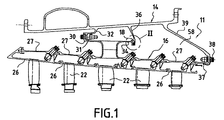
従来技術に関連する図1および図2をより詳細に考慮すると、航空機ジェットエンジンの構成の一部をなすターボコンプレッサ11が示されている。2つのサブアセンブリ14、16は、軸方向応力のもとで組み立てられ、かつそれらサブアセンブリの間に、シール20が内部に挿入される、環状室18を画定している。サブアセンブリ14は、外側ケーシングを構成するのに対して、サブアセンブリ16は、ターボコンプレッサの複数の固定ブレード22のための支持体を構成する。図示されていない可動ブレードは、固定ブレードの間に配置される。固定ブレード支持体は、端と端とをつないで組み立てられるいくつかのセグメント26によって構成され、各セグメントは、一連の固定ブレードを支持する。支持体アセンブリは、内側ケーシング27に固定される。この内側ケーシングは、3つの環状リングによって径方向外向きに延びる。第1のリング30は、外側ケーシングの第1の内部部材32に1組のボルト31によって固定され、第2のリング34は、外側ケーシングの第2の内向きに延びる部材36に、応力なしに圧接している。第3のリング37は、1組のボルト38によって、外側ケーシング14の内部部材39に固定される。
Considering in more detail FIGS. 1 and 2 related to the prior art, a
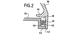
図2においてさらに明確に見られるように、第2のリング34は、平坦な環状面40を備え、この平坦な環状面40は、径方向内向きへ延びており、その環状領域43によって前記第2の部材36に圧接している軸方向円筒状部分42によって延長される。より詳細には、第2の部材は、他の平坦な環状面45を備え、この他の平坦な環状面45は、第2のリングの外側円筒部分を、間隔を有して覆うほぼ管状の突出部46の上に載置されるリングの面に対向している。したがってこの配置は、2つの平坦面40、45に圧接されるシール20が、その中に設置される環状室18を画定している。上述されたように、サブアセンブリ14、16の寸法設定は、アセンブリが、ボルト31の締め付けに起因する応力で作られるようにしてなされる。したがってこの応力は、第2のリングの環状領域43と、第2の部材の平坦面45の内側端部との間に加えられる。これまでに説明されたこの構成は、従来の構成である。しかしながら、アセンブリ応力は、0.3mm程度と比較的低いものであった。特定の場合においては、上述されたとおりの、漏洩およびシールの破壊の問題を完全に解決できずに、応力は、0.75mmまで増大されている。
As can be seen more clearly in FIG. 2, the
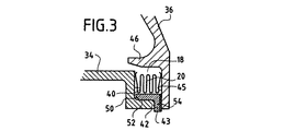
本発明は、図3に示され、かつ2つのサブアセンブリの圧接面の間に、すなわちこの場合、リング34の環状領域43と部材36の平坦面45の環状端部との間に、環状介挿部品50の配置を提案する。この部品50の存在は、以後、1.5mmから3mm、典型的には約2.25mmであり得る、フィッティング応力の増大を可能にする。実際に、介挿部品50は、少なくとも1つの環状部品の端部における接触面積、この場合より詳細には、前記第2の部材36の平坦面45を増大させるように形成されていることが分かる。さらにリングの軸方向円筒状部分42は、介挿部品50が、前記円筒状部分42にそれ自体がはめ合う円筒面52を備えているという事実のために、介挿部品50の配置をガイドすることを可能にする。介挿部品の径方向部分54は、前記第2の部材の平坦面45を押圧する。包括的には、図3に明確に見られるように、介挿部品50径方向断面は、それゆえL字状に形成されている。介挿部品は、はめ合う前に、その強度を増大させる表面処理を受けることができる。この処理は、特に、径方向部分54に適用することができる。したがって、リングに対してまたは部材に対して、このタイプの処理を適用することは必ずしも必要ではない。
The present invention is shown in FIG. 3 and between the pressure contact surfaces of the two subassemblies, ie in this case between the
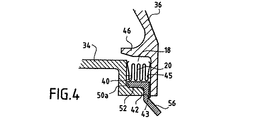
変形形態として、図4に示されるように、介挿部品50aは、デフレクタ56を形成する部分によって内方に延びる。この例において、この部分は実質的に円錐形状を有している。したがって、残留漏洩の場合に、高温空気が、内側ケーシングに局部的にあたることがもはやなくなるが、ケーシングとブレード支持体との間に画定される室58内に拡散される。
As a variant, as shown in FIG. 4, the
11 ターボコンプレッサ
14、16 サブアセンブリ
18 環状室
20 シール
26 セグメント
27 内側ケーシング
30 第1のリング
31、38 ボルト
32 第1の内部部材
34 第2のリング
36 第2の部材
39 内部部材
40、45 平坦環状面
42 円筒状部分
43 環状領域
50 介挿部品
54 径方向部分
56 デフレクタ
58 室
Claims (7)
Applications Claiming Priority (1)
| Application Number | Priority Date | Filing Date | Title |
|---|---|---|---|
| FR0403128A FR2868125B1 (en) | 2004-03-26 | 2004-03-26 | TURBOMACHINE COMPRISING TWO SUBASSEMBLIES ASSEMBLED WITH AXIAL CONSTRAINTS |
Publications (2)
| Publication Number | Publication Date |
|---|---|
| JP2005291203A true JP2005291203A (en) | 2005-10-20 |
| JP4643326B2 JP4643326B2 (en) | 2011-03-02 |
Family
ID=34855166
Family Applications (1)
| Application Number | Title | Priority Date | Filing Date |
|---|---|---|---|
| JP2005085761A Expired - Lifetime JP4643326B2 (en) | 2004-03-26 | 2005-03-24 | Turboshaft engine with two subassemblies assembled under axial stress |
Country Status (9)
| Country | Link |
|---|---|
| US (1) | US7571614B2 (en) |
| EP (1) | EP1580402B1 (en) |
| JP (1) | JP4643326B2 (en) |
| CA (1) | CA2500947C (en) |
| DE (1) | DE602005001641T2 (en) |
| ES (1) | ES2290863T3 (en) |
| FR (1) | FR2868125B1 (en) |
| RU (1) | RU2380546C2 (en) |
| UA (1) | UA86354C2 (en) |
Families Citing this family (7)
| Publication number | Priority date | Publication date | Assignee | Title |
|---|---|---|---|---|
| FR2898641B1 (en) * | 2006-03-17 | 2008-05-02 | Snecma Sa | CARTERING IN A TURBOJET ENGINE |
| US8197186B2 (en) * | 2007-06-29 | 2012-06-12 | General Electric Company | Flange with axially extending holes for gas turbine engine clearance control |
| US8393855B2 (en) * | 2007-06-29 | 2013-03-12 | General Electric Company | Flange with axially curved impingement surface for gas turbine engine clearance control |
| US8998573B2 (en) * | 2010-10-29 | 2015-04-07 | General Electric Company | Resilient mounting apparatus for low-ductility turbine shroud |
| EP2886802B1 (en) * | 2013-12-20 | 2019-04-10 | Safran Aero Boosters SA | Gasket of the inner ferrule of the last stage of an axial turbomachine compressor |
| US10202863B2 (en) * | 2016-05-23 | 2019-02-12 | United Technologies Corporation | Seal ring for gas turbine engines |
| US10392967B2 (en) | 2017-11-13 | 2019-08-27 | General Electric Company | Compliant seal component and associated method |
Citations (4)
| Publication number | Priority date | Publication date | Assignee | Title |
|---|---|---|---|---|
| JPH06173705A (en) * | 1992-08-26 | 1994-06-21 | General Electric Co <Ge> | Turbo shaft engine |
| JPH11343809A (en) * | 1998-06-02 | 1999-12-14 | Ishikawajima Harima Heavy Ind Co Ltd | Seal structure of turbine shroud part of gas turbine |
| JP2003201807A (en) * | 2001-11-28 | 2003-07-18 | General Electric Co <Ge> | Suppression seal with thermal compliance |
| JP2003222029A (en) * | 2001-12-28 | 2003-08-08 | General Electric Co <Ge> | Auxiliary seal for string hinge seal in gas turbine |
Family Cites Families (13)
| Publication number | Priority date | Publication date | Assignee | Title |
|---|---|---|---|---|
| GB1412469A (en) * | 1972-11-04 | 1975-11-05 | Semt | Sealing packing or joint forming in particular a cylinder head gasket for an internal-combustion reciprocating piston engine |
| US4336943A (en) * | 1980-11-14 | 1982-06-29 | United Technologies Corporation | Wedge-shaped seal for flanged joints |
| LU86209A1 (en) * | 1985-12-12 | 1987-01-13 | Euratom | SEALING SYSTEM BETWEEN TWO METAL FLANGES |
| FR2646221B1 (en) * | 1989-04-19 | 1991-06-14 | Snecma | SEAL, DEVICE COMPRISING SAME AND APPLICATION TO A TURBOMACHINE |
| GB2239678B (en) * | 1989-12-08 | 1993-03-03 | Rolls Royce Plc | Gas turbine engine blade shroud assembly |
| RU2042834C1 (en) * | 1992-02-04 | 1995-08-27 | Акционерное общество Самарский научно-технический комплекс "Двигатели НК" | Sealing joints of flanges of blading nozzle box of turbine |
| FR2695164B1 (en) * | 1992-08-26 | 1994-11-04 | Snecma | Turbomachine provided with a device preventing a longitudinal circulation of gas around the stages of straightening vanes. |
| EP0921273B1 (en) * | 1997-06-11 | 2003-12-03 | Mitsubishi Heavy Industries, Ltd. | Rotor for gas turbines |
| FR2766517B1 (en) * | 1997-07-24 | 1999-09-03 | Snecma | DEVICE FOR VENTILATION OF A TURBOMACHINE RING |
| US6237921B1 (en) * | 1998-09-02 | 2001-05-29 | General Electric Company | Nested bridge seal |
| US6402466B1 (en) * | 2000-05-16 | 2002-06-11 | General Electric Company | Leaf seal for gas turbine stator shrouds and a nozzle band |
| US6450762B1 (en) * | 2001-01-31 | 2002-09-17 | General Electric Company | Integral aft seal for turbine applications |
| RU2302534C2 (en) * | 2001-12-11 | 2007-07-10 | Альстом (Свитзерлэнд) Лтд. | Gas-turbine device |
-
2004
- 2004-03-26 FR FR0403128A patent/FR2868125B1/en not_active Expired - Fee Related
-
2005
- 2005-03-23 US US11/086,359 patent/US7571614B2/en active Active
- 2005-03-23 CA CA2500947A patent/CA2500947C/en not_active Expired - Lifetime
- 2005-03-24 JP JP2005085761A patent/JP4643326B2/en not_active Expired - Lifetime
- 2005-03-25 EP EP05290663A patent/EP1580402B1/en not_active Expired - Lifetime
- 2005-03-25 RU RU2005108494/06A patent/RU2380546C2/en active
- 2005-03-25 DE DE602005001641T patent/DE602005001641T2/en not_active Expired - Lifetime
- 2005-03-25 UA UAA200502763A patent/UA86354C2/en unknown
- 2005-03-25 ES ES05290663T patent/ES2290863T3/en not_active Expired - Lifetime
Patent Citations (4)
| Publication number | Priority date | Publication date | Assignee | Title |
|---|---|---|---|---|
| JPH06173705A (en) * | 1992-08-26 | 1994-06-21 | General Electric Co <Ge> | Turbo shaft engine |
| JPH11343809A (en) * | 1998-06-02 | 1999-12-14 | Ishikawajima Harima Heavy Ind Co Ltd | Seal structure of turbine shroud part of gas turbine |
| JP2003201807A (en) * | 2001-11-28 | 2003-07-18 | General Electric Co <Ge> | Suppression seal with thermal compliance |
| JP2003222029A (en) * | 2001-12-28 | 2003-08-08 | General Electric Co <Ge> | Auxiliary seal for string hinge seal in gas turbine |
Also Published As
| Publication number | Publication date |
|---|---|
| RU2380546C2 (en) | 2010-01-27 |
| CA2500947A1 (en) | 2005-09-26 |
| ES2290863T3 (en) | 2008-02-16 |
| EP1580402A1 (en) | 2005-09-28 |
| CA2500947C (en) | 2012-11-20 |
| DE602005001641D1 (en) | 2007-08-30 |
| UA86354C2 (en) | 2009-04-27 |
| US20050260066A1 (en) | 2005-11-24 |
| JP4643326B2 (en) | 2011-03-02 |
| FR2868125A1 (en) | 2005-09-30 |
| EP1580402B1 (en) | 2007-07-18 |
| FR2868125B1 (en) | 2006-07-21 |
| DE602005001641T2 (en) | 2008-06-05 |
| RU2005108494A (en) | 2006-09-27 |
| US7571614B2 (en) | 2009-08-11 |
Similar Documents
| Publication | Publication Date | Title |
|---|---|---|
| US8186692B2 (en) | Split ring seal with spring element | |
| RU2476710C2 (en) | Rotor ring seal in turbine stage | |
| JP4938872B2 (en) | Shaft seal on compressor side of exhaust gas turbocharger | |
| EP2570612B1 (en) | Turbomachine secondary seal assembly | |
| US9562441B2 (en) | Turbo machine with a device for preventing a segment of nozzle guide vanes assembly from rotating in a casing; rotation-proofing peg | |
| JP6441611B2 (en) | Gas turbine exhaust member and exhaust chamber maintenance method | |
| JP5376845B2 (en) | Mounting the shaft in a bearing containing a self-releasing nut | |
| KR101195543B1 (en) | Turbomachine and rotor-shaft seal | |
| CN101779018A (en) | Turbo charger | |
| US9835049B2 (en) | Turbomachine distributor comprising a thermal protection sheet with a radial stop, and associated thermal protection sheet | |
| CN101713303A (en) | Method and apparatus for matching the thermal mass and stiffness of bolted split rings | |
| JP2005264939A (en) | Bearing seal with backup device | |
| US10669875B2 (en) | Cross key anti-rotation spacer | |
| JP2009243312A (en) | Cover for cooling passage, method of manufacturing the cover, and gas turbine | |
| JP2018048632A (en) | Turbocharger | |
| JP4643326B2 (en) | Turboshaft engine with two subassemblies assembled under axial stress | |
| WO2014087966A1 (en) | Centrifugal compressor, supercharger with same, and method for operating centrifugal compressor | |
| JP6782840B2 (en) | Turbocharger with a sealing surface between the nozzle ring and the turbine housing | |
| JP2016008575A (en) | Variable geometry type supercharger | |
| US9664067B2 (en) | Seal retaining assembly | |
| CN112272733B (en) | Turboshaft assembly, supercharger and supercharger manufacturing method | |
| JP6845638B2 (en) | Steam turbine inner casing with modular inserts | |
| JP2004316509A (en) | Sealing structure of turbine casing | |
| JP2002013401A (en) | Exhauster of gas turbine | |
| US20230111341A1 (en) | Rotor arrangement for a gas turbine with inclined axial contact surfaces formed on rotor segments, gas turbine and aircraft gas turbine |
Legal Events
| Date | Code | Title | Description |
|---|---|---|---|
| A621 | Written request for application examination |
Free format text: JAPANESE INTERMEDIATE CODE: A621 Effective date: 20080116 |
|
| A131 | Notification of reasons for refusal |
Free format text: JAPANESE INTERMEDIATE CODE: A131 Effective date: 20100511 |
|
| A521 | Request for written amendment filed |
Free format text: JAPANESE INTERMEDIATE CODE: A523 Effective date: 20100810 |
|
| TRDD | Decision of grant or rejection written | ||
| A01 | Written decision to grant a patent or to grant a registration (utility model) |
Free format text: JAPANESE INTERMEDIATE CODE: A01 Effective date: 20101109 |
|
| A01 | Written decision to grant a patent or to grant a registration (utility model) |
Free format text: JAPANESE INTERMEDIATE CODE: A01 |
|
| A61 | First payment of annual fees (during grant procedure) |
Free format text: JAPANESE INTERMEDIATE CODE: A61 Effective date: 20101202 |
|
| R150 | Certificate of patent or registration of utility model |
Ref document number: 4643326 Country of ref document: JP Free format text: JAPANESE INTERMEDIATE CODE: R150 Free format text: JAPANESE INTERMEDIATE CODE: R150 |
|
| FPAY | Renewal fee payment (event date is renewal date of database) |
Free format text: PAYMENT UNTIL: 20131210 Year of fee payment: 3 |
|
| R250 | Receipt of annual fees |
Free format text: JAPANESE INTERMEDIATE CODE: R250 |
|
| R250 | Receipt of annual fees |
Free format text: JAPANESE INTERMEDIATE CODE: R250 |
|
| R250 | Receipt of annual fees |
Free format text: JAPANESE INTERMEDIATE CODE: R250 |
|
| R250 | Receipt of annual fees |
Free format text: JAPANESE INTERMEDIATE CODE: R250 |
|
| R250 | Receipt of annual fees |
Free format text: JAPANESE INTERMEDIATE CODE: R250 |
|
| R250 | Receipt of annual fees |
Free format text: JAPANESE INTERMEDIATE CODE: R250 |
|
| R250 | Receipt of annual fees |
Free format text: JAPANESE INTERMEDIATE CODE: R250 |
|
| R250 | Receipt of annual fees |
Free format text: JAPANESE INTERMEDIATE CODE: R250 |
|
| R250 | Receipt of annual fees |
Free format text: JAPANESE INTERMEDIATE CODE: R250 |
|
| R250 | Receipt of annual fees |
Free format text: JAPANESE INTERMEDIATE CODE: R250 |
|
| R250 | Receipt of annual fees |
Free format text: JAPANESE INTERMEDIATE CODE: R250 |
|
| R250 | Receipt of annual fees |
Free format text: JAPANESE INTERMEDIATE CODE: R250 |
|
| EXPY | Cancellation because of completion of term |