JP4474088B2 - Method for reducing seal tooth wear, honeycomb seal and gas turbine engine - Google Patents
Method for reducing seal tooth wear, honeycomb seal and gas turbine engine Download PDFInfo
- Publication number
- JP4474088B2 JP4474088B2 JP2002031598A JP2002031598A JP4474088B2 JP 4474088 B2 JP4474088 B2 JP 4474088B2 JP 2002031598 A JP2002031598 A JP 2002031598A JP 2002031598 A JP2002031598 A JP 2002031598A JP 4474088 B2 JP4474088 B2 JP 4474088B2
- Authority
- JP
- Japan
- Prior art keywords
- seal
- honeycomb
- teeth
- gas turbine
- turbine engine
- Prior art date
- Legal status (The legal status is an assumption and is not a legal conclusion. Google has not performed a legal analysis and makes no representation as to the accuracy of the status listed.)
- Expired - Fee Related
Links
Images


Classifications
-
- F—MECHANICAL ENGINEERING; LIGHTING; HEATING; WEAPONS; BLASTING
- F01—MACHINES OR ENGINES IN GENERAL; ENGINE PLANTS IN GENERAL; STEAM ENGINES
- F01D—NON-POSITIVE DISPLACEMENT MACHINES OR ENGINES, e.g. STEAM TURBINES
- F01D11/00—Preventing or minimising internal leakage of working-fluid, e.g. between stages
- F01D11/08—Preventing or minimising internal leakage of working-fluid, e.g. between stages for sealing space between rotor blade tips and stator
- F01D11/12—Preventing or minimising internal leakage of working-fluid, e.g. between stages for sealing space between rotor blade tips and stator using a rubstrip, e.g. erodible. deformable or resiliently-biased part
- F01D11/127—Preventing or minimising internal leakage of working-fluid, e.g. between stages for sealing space between rotor blade tips and stator using a rubstrip, e.g. erodible. deformable or resiliently-biased part with a deformable or crushable structure, e.g. honeycomb
-
- F—MECHANICAL ENGINEERING; LIGHTING; HEATING; WEAPONS; BLASTING
- F01—MACHINES OR ENGINES IN GENERAL; ENGINE PLANTS IN GENERAL; STEAM ENGINES
- F01D—NON-POSITIVE DISPLACEMENT MACHINES OR ENGINES, e.g. STEAM TURBINES
- F01D5/00—Blades; Blade-carrying members; Heating, heat-insulating, cooling or antivibration means on the blades or the members
- F01D5/12—Blades
- F01D5/22—Blade-to-blade connections, e.g. for damping vibrations
- F01D5/225—Blade-to-blade connections, e.g. for damping vibrations by shrouding
-
- F—MECHANICAL ENGINEERING; LIGHTING; HEATING; WEAPONS; BLASTING
- F16—ENGINEERING ELEMENTS AND UNITS; GENERAL MEASURES FOR PRODUCING AND MAINTAINING EFFECTIVE FUNCTIONING OF MACHINES OR INSTALLATIONS; THERMAL INSULATION IN GENERAL
- F16J—PISTONS; CYLINDERS; SEALINGS
- F16J15/00—Sealings
- F16J15/44—Free-space packings
- F16J15/444—Free-space packings with facing materials having honeycomb-like structure
-
- Y—GENERAL TAGGING OF NEW TECHNOLOGICAL DEVELOPMENTS; GENERAL TAGGING OF CROSS-SECTIONAL TECHNOLOGIES SPANNING OVER SEVERAL SECTIONS OF THE IPC; TECHNICAL SUBJECTS COVERED BY FORMER USPC CROSS-REFERENCE ART COLLECTIONS [XRACs] AND DIGESTS
- Y02—TECHNOLOGIES OR APPLICATIONS FOR MITIGATION OR ADAPTATION AGAINST CLIMATE CHANGE
- Y02T—CLIMATE CHANGE MITIGATION TECHNOLOGIES RELATED TO TRANSPORTATION
- Y02T50/00—Aeronautics or air transport
- Y02T50/60—Efficient propulsion technologies, e.g. for aircraft
Description
【0001】
【発明の属する技術分野】
本発明は、一般的にガスタービンエンジンに関し、より具体的には、ガスタービンエンジンに含まれるハニカムシールに関する。
【0002】
【従来の技術】
ハニカムシールは、航空機、船舶及び産業動力用タービンエンジンに広く使用されている。例えば、一般にガスタービンエンジンは、少なくとも1列のロータブレード、及びロータ組立体中に形成された空洞内の複数のハニカムシールを含む。一般に、1150°C(2100°F)を超える融解温度を持つハニカム材料、例えばHastelloy Xが、背板に鑞付けされる。エンジンのならし運転中に、第1の回転環状部材に設置されたシール歯は、第2の非回転部材あるいは第1の回転部材の回転速度と異なる回転速度を持つ第2の回転部材のいずれかに設置されたハニカムシールに凹部あるいは溝を切り込む。シール歯を備える第1の回転環状部材により切り込まれた溝は、シール歯とハニカム材料の間の作動間隙を構成し、ハニカム材料がシール歯に対してシールを行うことを可能にし、空気がシール歯及びハニカム材料により形成される空洞間を流れるのを阻止する。
【特許文献1】
特開2001−200798号公報
【0003】
【発明が解決しようとする課題】
エンジンのならし運転及び正常運転状態の間に、シール歯は低い進入度合でハニカム材料に切り込む。高いあるいは急速な進入度合は、例えば公差を厳しくした結果などの場合に生じる可能性がある。高い進入度合が起こる可能性がある別の場合は、現用のタービンに整備を実施した後とか、タービンモジュール構成部品を置き換えるか、あるいは取替えた後である。高い進入度合での運転中に、シール歯とハニカム材料の間に発生する摩擦熱は、シール歯の温度を正常な作動温度からハニカム材料の融解温度を僅かに下まわる温度値まで上昇させる。温度が上昇すると、シール歯は有効にハニカム材料に切り込まれず、むしろシール歯に接触すると、ハニカムセルは、降伏し「スミアする」ことになる。シール歯は有効にハニカム材料に切り込まれないので、高いシール摩擦トルクが発生し、シール歯とハニカム材料の間に発生する摩擦熱はさらに増大する。
【0004】
シール歯内に生じる温度が上昇すると、シール歯の材料の劣化、疲労割れ及び焼き割れの可能性の原因となる。時間の経過と共に、継続して高温に曝されることによりシール歯は降伏応力を上回る結果となり、従ってシール歯の疲労寿命及び劣化を生じる可能性がある残留応力を招くことになる。さらに、ハニカム材料が、回転部材のブレードから均一な距離でタービンの周りに円周方向に配置されていない場合には、局所的な摩擦が起きる可能性がある。シール歯の局所的摩擦と温度上昇が組み合わさると、ハニカム材料中に正弦温度勾配及び強度の摩擦を引き起こすことになる。さらに、より強度の摩擦の結果、作動間隙が局所的に増加し、空気が回転部材とハニカム材料の間を流れ、シールの有効性を低下させることになる。
【0005】
【課題を解決するための手段】
例示的な実施形態では、ガスタービンエンジンはガスタービンエンジン内に配置されたシール歯の摩耗を減少させるハニカムシールを備える非回転組立体を含む。ガスタービンエンジンの非回転組立体は、ロータ構成部品とステータ構成部品の間に配置されたシール組立体を含む。ロータ構成部品は、回転環状部材から半径方向外方に延びるシール歯を備える回転環状部材を含む。ステータ構成部品は、半径方向内方に延びるハニカムシールを備える非回転部材を含む。ハニカムシールは、およそ1095°C(2000°F)より低い融解温度をもつ材料で製作される。さらに、前記材料は、およそ871°C(1600°F)より高い融解温度を持つ。
【0006】
エンジン運転中、回転するシール歯はハニカム材料に接触し、ハニカム材料の融解温度より高くない温度を発生する。従って、シール歯がハニカム材料に接触するとき、シール歯によりハニカム中に容易に凹部あるいは溝が切り込まれる。溝はブレードのシール歯とハニカム材料の間の作動間隙を構成し、ハニカム材料がシール歯に対してシールを行うことを可能にし、空気がシール歯とハニカム材料の間を流れるのを阻止する。ハニカムシールの融解温度が1095°C(2000°F)より低いため、回転するシール歯がハニカムシールへ切り込まれるとき発生する温度上昇は、ハニカム材料の融解温度より低い温度に制限される。さらに、ハニカム材料の融解温度が1095°C(2000°F)より低いために、シール歯内に生じる温度上昇は、より高い融解温度の材料で製作される公知のハニカムシール中に切り込まれるシール歯内に生じる温度上昇に比較して、減少する。その結果的、熱応力によるシール歯の性状劣化及び割れが減少する。
【0007】
【発明の実施の形態】
図1は、低圧圧縮機12、高圧圧縮機14、及び燃焼器16を含むガスタービンエンジン10の概略図である。1つの実施形態では、エンジン10は高圧タービン18及び低圧タービン20を含む。圧縮機12及びタービン20は第1のシャフト21で連結され、圧縮機14及びタービン18は第2のシャフト22で連結される。
【0008】
運転中、空気は低圧圧縮機12を通って流れ、加圧された空気は低圧圧縮機12から高圧圧縮機14へ供給される。高度に加圧された空気は燃焼器16に供給される。燃焼器16からの空気流は回転タービン18及び20を駆動し、ノズル24を通してガスタービンエンジン10から流出する。
【0009】
図2は、ガスタービンエンジン10(図1に示す)のようなガスタービンエンジンに使用することができるロータ組立体100の部分概略図である。例示的な実施形態では、ロータ組立体100は、ハニカムシール102、複数のステータ羽根104、及び少なくとも1つの回転部材を含む。回転部材106はそこからケーシング112に向かって外側方向に延びる少なくとも1つのシール歯110を持つ先端108を含む。ケーシング112はステータ羽根104及び回転部材106の半径方向外側に配置される。
【0010】
ハニカムシール102は、回転部材106の周りに円周方向に延びており、ケーシング112に取り付けられる第1の端部114及び第2の端部116を含む。ハニカムシールの第1端部114は第1の接合具118でケーシング112に取り付けられ、ハニカムシールの第2端部116は第2の接合具120でケーシング112に取り付けられる。第2接合具120は、ハニカムシール102の第2端部116にばね力を与えて、ステータ羽根プラットフォーム122と接触するようにハニカムシール102を押し付け、その結果、エンジン100が運転していないときに、シール歯110はハニカムシール102から距離126を置いている。1つの実施形態では、ハニカムシール102は、以下にさらに詳細に説明する材料130を含み、軸方向突起132がケーシング112の軸方向凹部134の中に受け入れられるように、第1端部114でケーシング112の中に組み込まれる。
【0011】
エンジンの初期運転中は、図2に示すように、シール歯110はハニカムシール102から距離126を置いている。エンジン100の運転速度が増加するにつれ、シール歯110は半径方向外方に拡張し、ハニカムシール102に接触または摩擦し、ハニカムシール102中に凹部(図示せず)を切り込み、シール歯110とハニカムシール102の間に作動間隙(図示せず)を形成する。さらに具体的には、運転中、シール歯110はロータ(図示せず)によってケーシング112に対して回転し、ステータ羽根104はケーシング112に対して静止したままである。空気は、タービン100の上流側138からタービン100の下流側140へ流れる。タービン100が作動し十分な作動温度に達した後、シール歯110はハニカムシール102の中に延び、空気がシール歯110とハニカムシール102の間を流れるのを阻止する。
【0012】
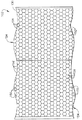
図3はハニカムシール102の拡大端面図である。ハニカムシール102は、ハニカム形状154に互いに接合された複数の薄い波板片152から形成された材料130で製作される。ハニカム形状154は複数のセル156及び各々のセル156を隔てる複数のセル壁158を含む。1つの実施形態では、セル156は六角形の形状を持つ。それに代えて、セル156は、円形、三角形、矩形、五角形、あるいはその他の形状とすることができる。
【0013】
材料130は、ハニカムシール102がエンジン運転中によくある過酷な環境条件に耐えることを可能にする真性的性質を持つ。具体的には、材料130は広範囲の温度及び圧力へ曝されることに耐えることができ、およそ1095°C(2000°F)以下の融解温度を持つ。1つの実施形態では、材料130はおよそ1055°C(1930°F)の融解温度を持つ合金材料からなる。別の実施形態では、ハニカム材料130は真鋳であり、およそ1650°Fの融解温度を持つ。さらに別の実施形態では、ハニカム材料130はアルミニウムであり、およそ566°C(1050°F)の融解温度を持つ。若しくは、材料130は耐環境条件性があり、1095°C(2000°F)より低い融解温度を持ち、およそ871°C(1600°F)より高い融解温度を持つ、いずれかの他の適切な材料あるいは複合材料である。
【0014】
ガスタービンエンジンの運転中、シール歯110の作動温度は、ハニカムシール102と摩擦する間に、ハニカムシール材料130の融解温度よりは高くない温度まで上昇する。ハニカムシール102の融解温度が1095°C(2000°F)より低いため、シール歯110内に生じる温度上昇は、およそ1095°C(2000°F)より低く制限され、またシール歯110とハニカムシール102の間の摩擦中も低く抑えられる。さらに、シール歯カッタの温度上昇が減少するために、ハニカムシール102と摩擦するシール歯カッタ特性への影響は減少する。具体的には、シール歯110に対する熱損傷が減少するので、シール歯の耐久性が改善される。さらに、熱応力によるシール歯110の特性劣化及び割れが減少する。
【0015】
摩擦中のシール歯110の温度上昇の可能性を低下させることにより、シール歯110に対する降伏応力が限度を超える時に発生する、シール歯110内に生じる残留応力も減少する。さらに、温度上昇が少なくなることによりシール歯110とハニカムシール102の間に生じるトルクがより少なくなり、従って、シール歯110の摩耗が少なくなる。さらに、温度上昇が低下することによりハニカムシール102内の割れ発生及びハニカムシール102の疲労劣化を減少させることができる。
【0016】
ハニカムシール102が、距離126(図2に示す)がガスタービンエンジン100の周りで円周方向に均一でない状態で、ガスタービンエンジン100(図1に示す)の中に取り付けられた場合、エンジン100運転中にシール歯110とハニカムシール102の間に局所的な摩擦が起きる可能性がある。局所的摩擦が生じている間にシール歯110とハニカムシール102の間に発生する熱は、シール歯110内に正弦温度勾配を生じる可能性がある。時間の経過と共に、そのような正弦温度勾配が強い場合には、より広い作動間隙を生じる。そのような正弦温度勾配の強さは、シール歯102に入力される熱量に比例する。従って、シール歯110の温度上昇の可能性が減少するので、発生する如何なる正弦温度勾配の強さも低下し、シール歯110とハニカムシール102の間の作動間隙が改善される。
【0017】
図4は、ガスタービンエンジン10に使用することができるラビリンスシール200を含むガスタービンエンジン10の一部の部分概略図である。ラビリンスシール200は、回転環状部材202の外周面206から半径方向に延びる複数のシール歯204を含む第1の回転環状部材202に適切に取り付けられて、シール歯204の外周部を構成する。
【0018】
ハニカムシール208は、第2の非回転部材210に適切に取り付けられ、半径方向内方に延びてハニカムシール208の内周部を構成する。ハニカムシール208は回転部材202の周りに円周方向に延びており、ハニカムシール102(図2に示す)と実質的に同様に、材料130(図3に示す)で製作される。それに代えて、ハニカムシール208は、第1の回転環状部材202上に配置されたシール歯204と、第1の回転部材202の回転速度と異なる回転速度を持つ第2の回転部材(図示せず)との間の空洞(図示せず)に配置されたラビリンスシール(図示せず)とすることができる。
【0019】
エンジンの初期運転中、シール歯204の外周部は、ハニカムシール208の内周部の小さい公差内で回転し、それによりエンジン10の軸方向に配置された部分間のシールを行う。エンジン10の運転速度が増加するにつれ、シール歯204は半径方向外方に拡張し、ハニカムシール208に接触または摩擦し、ハニカムシール208中に凹部(図示せず)を切り込み、シール歯204とハニカムシール208の間に作動間隙(図示せず)を形成する。さらに具体的には、運転中、シール歯204は回転部材202によって回転する。タービン10が作動し十分な作動温度に達した後、シール歯204はハニカムシール208の中に延び、空気がシール歯204とハニカムシール208の間を流れるのを阻止する。
【0020】
上述のガスタービンエンジンは費用効果がよく、信頼性が高い。ステータ組立体は、およそ1095°C(2000°F)より低い融解温度を持つ材料で製作されるハニカムシールを含む。エンジン運転中、シール歯はハニカムシールに接触し、熱を発生してハニカムシールの融解温度より高くない温度までその温度が上昇する。シール歯によりハニカムシールに溝が切り込まれるので、ハニカムシールはシール歯に対してシールを行って、空気がハニカムシールとシール歯の間を流れるのを阻止する。ハニカムシール材料の融解温度により、摩擦中のシール歯の作動温度は制限される。ハニカムシールの結果として、シール歯は公知のシール歯に比較して低い温度で作動され、より少ない熱応力及び摩耗を受ける。より具体的には、シール歯に対する熱損傷が減少するため、シール歯の耐久性が改善される。さらに、熱応力によるシール歯の特性劣化及び割れが減少する。従って、シール歯の摩擦中に生じる温度上昇の可能性が減少し、発生する如何なる温度勾配の強さも低下し、シール歯とハニカムシールの間の作動間隙が改善される。
【0021】
本発明を種々の具体的な実施形態について説明してきたが、本発明が特許請求の範囲の技術思想及び技術的範囲内の変更により実施できることは、当業者には明らかであろう。
【図面の簡単な説明】
【図1】 ガスタービンエンジンの概略図。
【図2】 図1に示すガスタービンエンジンに使用することができる低圧タービンの部分概略図。
【図3】 図2に示す低圧タービン組立体に使用することができるハニカムシール組立体の拡大端面図。
【図4】 図1に示すガスタービンエンジンに使用することができるラビリンスシールの部分概略図。
【符号の説明】
100 ロータ組立体
102 ハニカムシール
104 ステータ羽根
106 回転部材
108 回転部材の先端
110 シール歯
112 ケーシング
114 第1端部
116 第2端部
118 第1接合具
120 第2接合具
130 ハニカム材料[0001]
BACKGROUND OF THE INVENTION
The present invention relates generally to gas turbine engines, and more specifically to honeycomb seals included in gas turbine engines.
[0002]
[Prior art]
Honeycomb seals are widely used in aircraft, marine and industrial power turbine engines. For example, gas turbine engines typically include at least one row of rotor blades and a plurality of honeycomb seals in cavities formed in the rotor assembly. Generally, a honeycomb material having a melting temperature in excess of 1150 ° C. (2100 ° F.), such as Hastelloy X, is brazed to the backplate. During engine running-in, the seal teeth installed on the first rotating annular member are either the second non-rotating member or the second rotating member having a rotational speed different from the rotational speed of the first rotating member. A recess or groove is cut into the honeycomb seal installed in the crab. The groove cut by the first rotating annular member with the seal teeth constitutes the working gap between the seal teeth and the honeycomb material, allowing the honeycomb material to seal against the seal teeth, and the air It prevents flow between cavities formed by the seal teeth and honeycomb material.
[Patent Document 1]
Japanese Patent Laid-Open No. 2001-200808
[Problems to be solved by the invention]
During engine running-in and normal operating conditions, the seal teeth cut into the honeycomb material with a low degree of penetration. A high or rapid approach may occur, for example, as a result of tight tolerances. Another case where a high degree of entry can occur is after servicing the current turbine, after replacing or replacing turbine module components. During operation at a high degree of penetration, the frictional heat generated between the seal teeth and the honeycomb material raises the temperature of the seal teeth from a normal operating temperature to a temperature value slightly below the melting temperature of the honeycomb material. As the temperature rises, the seal teeth are not effectively cut into the honeycomb material, but rather contact the seal teeth and the honeycomb cells will yield and “smear”. Since the seal teeth are not effectively cut into the honeycomb material, a high seal friction torque is generated, and the frictional heat generated between the seal teeth and the honeycomb material is further increased.
[0004]
When the temperature generated in the seal teeth rises, it causes deterioration of the material of the seal teeth, fatigue cracks and possible cracks. Over time, continuous exposure to high temperatures results in the seal teeth exceeding the yield stress, thus leading to residual stresses that can cause fatigue life and degradation of the seal teeth. Furthermore, local friction may occur if the honeycomb material is not circumferentially arranged around the turbine at a uniform distance from the blades of the rotating member. The combination of local friction of the seal teeth and increased temperature will cause sinusoidal temperature gradients and strong friction in the honeycomb material. Furthermore, as a result of more intense friction, the working gap increases locally and air flows between the rotating member and the honeycomb material, reducing the effectiveness of the seal.
[0005]
[Means for Solving the Problems]
In an exemplary embodiment, a gas turbine engine includes a non-rotating assembly that includes a honeycomb seal that reduces wear of seal teeth disposed within the gas turbine engine. A non-rotating assembly of a gas turbine engine includes a seal assembly disposed between a rotor component and a stator component. The rotor component includes a rotating annular member with seal teeth extending radially outward from the rotating annular member. The stator component includes a non-rotating member with a honeycomb seal extending radially inward. The honeycomb seal is made of a material having a melting temperature below approximately 1095 ° C. (2000 ° F.). Further, the material has a melting temperature greater than approximately 871 ° C. (1600 ° F.).
[0006]
During engine operation, the rotating seal teeth contact the honeycomb material and generate a temperature not higher than the melting temperature of the honeycomb material. Therefore, when the seal teeth come into contact with the honeycomb material, the recesses or grooves are easily cut into the honeycomb by the seal teeth. The grooves form a working gap between the blade seal teeth and the honeycomb material, allowing the honeycomb material to seal against the seal teeth and preventing air from flowing between the seal teeth and the honeycomb material. Since the melting temperature of the honeycomb seal is lower than 1095 ° C. (2000 ° F.), the temperature rise that occurs when the rotating seal teeth are cut into the honeycomb seal is limited to a temperature lower than the melting temperature of the honeycomb material. In addition, because the melting temperature of the honeycomb material is lower than 1095 ° C. (2000 ° F.), the temperature rise that occurs in the seal teeth is a seal that is cut into known honeycomb seals made with higher melting temperature materials. Compared to the temperature rise that occurs in the teeth. As a result, the deterioration and cracking of the seal teeth due to thermal stress are reduced.
[0007]
DETAILED DESCRIPTION OF THE INVENTION
FIG. 1 is a schematic diagram of a
[0008]
During operation, air flows through
[0009]
FIG. 2 is a partial schematic diagram of a
[0010]
The
[0011]
During initial engine operation, the
[0012]
FIG. 3 is an enlarged end view of the
[0013]
The
[0014]
During operation of the gas turbine engine, the operating temperature of the
[0015]
By reducing the possibility of temperature rise of the
[0016]
When the
[0017]
FIG. 4 is a partial schematic view of a portion of a
[0018]
The
[0019]
During initial operation of the engine, the outer periphery of the
[0020]
The gas turbine engine described above is cost effective and highly reliable. The stator assembly includes a honeycomb seal made of a material having a melting temperature below approximately 1095 ° C. (2000 ° F.). During engine operation, the seal teeth come into contact with the honeycomb seal, generating heat and raising its temperature to a temperature not higher than the melting temperature of the honeycomb seal. Since the groove is cut into the honeycomb seal by the seal teeth, the honeycomb seal seals the seal teeth to prevent air from flowing between the honeycomb seal and the seal teeth. The melting temperature of the honeycomb sealing material limits the operating temperature of the seal teeth during friction. As a result of the honeycomb seal, the seal teeth are operated at a lower temperature and experience less thermal stress and wear compared to known seal teeth. More specifically, since the thermal damage to the seal teeth is reduced, the durability of the seal teeth is improved. In addition, the deterioration of the seal teeth and cracks due to thermal stress are reduced. Thus, the potential for temperature rise that occurs during friction of the seal teeth is reduced, the intensity of any temperature gradient that occurs is reduced, and the working gap between the seal teeth and the honeycomb seal is improved.
[0021]
While the invention has been described in terms of various specific embodiments, those skilled in the art will recognize that the invention can be practiced with modification within the spirit and scope of the claims.
[Brief description of the drawings]
FIG. 1 is a schematic view of a gas turbine engine.
FIG. 2 is a partial schematic diagram of a low pressure turbine that can be used in the gas turbine engine shown in FIG. 1;
FIG. 3 is an enlarged end view of a honeycomb seal assembly that can be used in the low pressure turbine assembly shown in FIG. 2;
4 is a partial schematic view of a labyrinth seal that can be used in the gas turbine engine shown in FIG. 1. FIG.
[Explanation of symbols]
DESCRIPTION OF
Claims (8)
前記合金材料(130)が、およそ871°C(1600°F)より高い融解温度を持つことを特徴とするハニカムシール(102)。A honeycomb seal (102) for a gas turbine engine (10) comprising an alloy material (130) excluding brass and phosphor bronze, the seal having a melting temperature lower than approximately 1095 ° C (2000 ° F). ,
A honeycomb seal (102), wherein the alloy material (130) has a melting temperature greater than approximately 871 ° C (1600 ° F).
前記合金材料(130)が、およそ871°C(1600°F)より高い融解温度を持つことを特徴とするガスタービンエンジン(10)。A gas turbine engine (10) comprising a rotor assembly (100) and a stator assembly, wherein the stator assembly has a melting temperature lower than about 1095 ° C (2000 ° F) , excluding brass and phosphor bronze. A honeycomb seal (102) made of material (130);
A gas turbine engine (10), wherein the alloy material (130) has a melting temperature greater than approximately 871 ° C (1600 ° F).
前記ハニカムシール(102)は、前記シール歯が前記ハニカムシールと摩擦するとき、前記シール歯(110)の摩耗を減少させるように構成されることを特徴とする、請求項5に記載のガスタービンエンジン(10)。The rotor assembly (100) includes a plurality of seal teeth (110);
The gas turbine of claim 5, wherein the honeycomb seal (102) is configured to reduce wear of the seal teeth (110) when the seal teeth rub against the honeycomb seal. Engine (10).
前記合金材料(130)は、前記シール歯(110)の疲労劣化を減少させるようにさらに構成されることを特徴とする、請求項5に記載のガスタービンエンジン(10)。The rotor assembly (100) includes a plurality of seal teeth (110);
The gas turbine engine (10) of claim 5, wherein the alloy material (130) is further configured to reduce fatigue degradation of the seal teeth (110).
Applications Claiming Priority (2)
| Application Number | Priority Date | Filing Date | Title |
|---|---|---|---|
| US09/783277 | 2001-02-09 | ||
| US09/783,277 US6652226B2 (en) | 2001-02-09 | 2001-02-09 | Methods and apparatus for reducing seal teeth wear |
Publications (3)
| Publication Number | Publication Date |
|---|---|
| JP2002309902A JP2002309902A (en) | 2002-10-23 |
| JP2002309902A5 JP2002309902A5 (en) | 2005-08-04 |
| JP4474088B2 true JP4474088B2 (en) | 2010-06-02 |
Family
ID=25128722
Family Applications (1)
| Application Number | Title | Priority Date | Filing Date |
|---|---|---|---|
| JP2002031598A Expired - Fee Related JP4474088B2 (en) | 2001-02-09 | 2002-02-08 | Method for reducing seal tooth wear, honeycomb seal and gas turbine engine |
Country Status (3)
| Country | Link |
|---|---|
| US (1) | US6652226B2 (en) |
| EP (1) | EP1231420A3 (en) |
| JP (1) | JP4474088B2 (en) |
Families Citing this family (45)
| Publication number | Priority date | Publication date | Assignee | Title |
|---|---|---|---|---|
| US7059821B2 (en) * | 2003-05-07 | 2006-06-13 | General Electric Company | Method and apparatus to facilitate sealing within turbines |
| US20040239040A1 (en) * | 2003-05-29 | 2004-12-02 | Burdgick Steven Sebastian | Nozzle interstage seal for steam turbines |
| US7234918B2 (en) * | 2004-12-16 | 2007-06-26 | Siemens Power Generation, Inc. | Gap control system for turbine engines |
| US8011883B2 (en) * | 2004-12-29 | 2011-09-06 | United Technologies Corporation | Gas turbine engine blade tip clearance apparatus and method |
| US7407369B2 (en) * | 2004-12-29 | 2008-08-05 | United Technologies Corporation | Gas turbine engine blade tip clearance apparatus and method |
| US7341426B2 (en) * | 2004-12-29 | 2008-03-11 | United Technologies Corporation | Gas turbine engine blade tip clearance apparatus and method |
| DE102005002270A1 (en) * | 2005-01-18 | 2006-07-20 | Mtu Aero Engines Gmbh | engine |
| US20070132193A1 (en) * | 2005-12-13 | 2007-06-14 | Wolfe Christopher E | Compliant abradable sealing system and method for rotary machines |
| US20070137039A1 (en) * | 2005-12-20 | 2007-06-21 | General Electric Company | Methods and apparatus for coupling honeycomb seals to gas turbine engine components |
| FR2899274B1 (en) * | 2006-03-30 | 2012-08-17 | Snecma | DEVICE FOR FASTENING RING SECTIONS AROUND A TURBINE WHEEL OF A TURBOMACHINE |
| US8074998B2 (en) * | 2006-05-05 | 2011-12-13 | The Texas A&M University System | Annular seals for non-contact sealing of fluids in turbomachinery |
| US20070273104A1 (en) * | 2006-05-26 | 2007-11-29 | Siemens Power Generation, Inc. | Abradable labyrinth tooth seal |
| US7511516B2 (en) * | 2006-06-13 | 2009-03-31 | General Electric Company | Methods and systems for monitoring the displacement of turbine blades |
| US7971882B1 (en) * | 2007-01-17 | 2011-07-05 | Florida Turbine Technologies, Inc. | Labyrinth seal |
| US20090097979A1 (en) * | 2007-07-31 | 2009-04-16 | Omer Duane Erdmann | Rotor blade |
| US20090072488A1 (en) * | 2007-09-18 | 2009-03-19 | Honeywell International, Inc. | Labyrinth seals and methods of manufacture |
| FR2923525B1 (en) * | 2007-11-13 | 2009-12-18 | Snecma | SEALING A ROTOR RING IN A TURBINE FLOOR |
| US8282346B2 (en) * | 2009-04-06 | 2012-10-09 | General Electric Company | Methods, systems and/or apparatus relating to seals for turbine engines |
| DE102009016803A1 (en) * | 2009-04-09 | 2010-10-14 | Rolls-Royce Deutschland Ltd & Co Kg | Labyrinth rubbing seal for a turbomachine |
| US8608424B2 (en) * | 2009-10-09 | 2013-12-17 | General Electric Company | Contoured honeycomb seal for a turbomachine |
| US8939715B2 (en) * | 2010-03-22 | 2015-01-27 | General Electric Company | Active tip clearance control for shrouded gas turbine blades and related method |
| US20130017070A1 (en) * | 2011-07-13 | 2013-01-17 | General Electric Company | Turbine seal, turbine, and process of fabricating a turbine seal |
| US20130106061A1 (en) * | 2011-10-28 | 2013-05-02 | General Electric Company | High temperature seal system |
| US9109458B2 (en) | 2011-11-11 | 2015-08-18 | United Technologies Corporation | Turbomachinery seal |
| US9109608B2 (en) * | 2011-12-15 | 2015-08-18 | Siemens Energy, Inc. | Compressor airfoil tip clearance optimization system |
| US9291061B2 (en) * | 2012-04-13 | 2016-03-22 | General Electric Company | Turbomachine blade tip shroud with parallel casing configuration |
| US8936431B2 (en) | 2012-06-08 | 2015-01-20 | General Electric Company | Shroud for a rotary machine and methods of assembling same |
| US9574455B2 (en) | 2012-07-16 | 2017-02-21 | United Technologies Corporation | Blade outer air seal with cooling features |
| US9115596B2 (en) * | 2012-08-07 | 2015-08-25 | United Technologies Corporation | Blade outer air seal having anti-rotation feature |
| US20140064969A1 (en) * | 2012-08-29 | 2014-03-06 | Dmitriy A. Romanov | Blade outer air seal |
| EP2728122B1 (en) * | 2012-10-30 | 2018-12-12 | MTU Aero Engines AG | Blade Outer Air Seal fixing for a turbomachine |
| US9194247B2 (en) | 2012-11-14 | 2015-11-24 | General Electric Company | Rotating seal configuration and method of sealing a rotating member to a housing |
| US9803491B2 (en) * | 2012-12-31 | 2017-10-31 | United Technologies Corporation | Blade outer air seal having shiplap structure |
| JP6184173B2 (en) | 2013-05-29 | 2017-08-23 | 三菱日立パワーシステムズ株式会社 | gas turbine |
| WO2015084550A1 (en) * | 2013-12-03 | 2015-06-11 | United Technologies Corporation | Heat shields for air seals |
| EP2881545B1 (en) * | 2013-12-04 | 2017-05-31 | MTU Aero Engines GmbH | Sealing element, sealing device and gas turbine engine |
| EP3172410B1 (en) | 2014-07-24 | 2018-05-16 | Siemens Aktiengesellschaft | Stator vane system usable within a gas turbine engine |
| CA2932601C (en) | 2015-06-17 | 2023-10-03 | Rolls-Royce Corporation | Labyrinth seal with tunable flow splitter |
| EP3153671A1 (en) | 2015-10-08 | 2017-04-12 | MTU Aero Engines GmbH | Protection device for a turbomachine |
| US20170211407A1 (en) * | 2016-01-21 | 2017-07-27 | General Electric Company | Flow alignment devices to improve diffuser performance |
| US10718352B2 (en) | 2016-07-26 | 2020-07-21 | Rolls-Royce Corporation | Multi-cellular abradable liner |
| US9816388B1 (en) * | 2016-09-22 | 2017-11-14 | General Electric Company | Seal in a gas turbine engine having a shim base and a honeycomb structure with a number of cavities formed therein |
| US10774670B2 (en) * | 2017-06-07 | 2020-09-15 | General Electric Company | Filled abradable seal component and associated methods thereof |
| JP6782671B2 (en) * | 2017-07-10 | 2020-11-11 | 三菱重工業株式会社 | Turbomachinery |
| WO2019013665A1 (en) | 2017-07-14 | 2019-01-17 | Siemens Aktiengesellschaft | Seal arrangement with highly elongated fin tip |
Family Cites Families (20)
| Publication number | Priority date | Publication date | Assignee | Title |
|---|---|---|---|---|
| US2742224A (en) * | 1951-03-30 | 1956-04-17 | United Aircraft Corp | Compressor casing lining |
| US2963307A (en) * | 1954-12-28 | 1960-12-06 | Gen Electric | Honeycomb seal |
| US3042365A (en) * | 1957-11-08 | 1962-07-03 | Gen Motors Corp | Blade shrouding |
| US3053694A (en) * | 1961-02-20 | 1962-09-11 | Gen Electric | Abradable material |
| US3547455A (en) * | 1969-05-02 | 1970-12-15 | Gen Electric | Rotary seal including organic abradable material |
| US3836156A (en) * | 1971-07-19 | 1974-09-17 | United Aircraft Canada | Ablative seal |
| US4022481A (en) * | 1973-02-23 | 1977-05-10 | International Harvester Company | Compliant structural members |
| US4087199A (en) | 1976-11-22 | 1978-05-02 | General Electric Company | Ceramic turbine shroud assembly |
| US4198839A (en) | 1978-04-19 | 1980-04-22 | General Electric Company | Method for making lightweight composite article |
| US4289447A (en) | 1979-10-12 | 1981-09-15 | General Electric Company | Metal-ceramic turbine shroud and method of making the same |
| US4460185A (en) | 1982-08-23 | 1984-07-17 | General Electric Company | Seal including a non-metallic abradable material |
| US4618152A (en) * | 1983-01-13 | 1986-10-21 | Thomas P. Mahoney | Honeycomb seal structure |
| US4767267A (en) | 1986-12-03 | 1988-08-30 | General Electric Company | Seal assembly |
| US4867639A (en) * | 1987-09-22 | 1989-09-19 | Allied-Signal Inc. | Abradable shroud coating |
| US5029876A (en) | 1988-12-14 | 1991-07-09 | General Electric Company | Labyrinth seal system |
| US5096376A (en) * | 1990-08-29 | 1992-03-17 | General Electric Company | Low windage corrugated seal facing strip |
| US5218816A (en) * | 1992-01-28 | 1993-06-15 | General Electric Company | Seal exit flow discourager |
| US5388959A (en) | 1993-08-23 | 1995-02-14 | General Electric Company | Seal including a non-metallic abradable material |
| DE19828065A1 (en) * | 1998-06-24 | 1999-12-30 | Bmw Rolls Royce Gmbh | Honeycomb structure seal especially for a gas turbine |
| US6290455B1 (en) | 1999-12-03 | 2001-09-18 | General Electric Company | Contoured hardwall containment |
-
2001
- 2001-02-09 US US09/783,277 patent/US6652226B2/en not_active Expired - Lifetime
-
2002
- 2002-02-07 EP EP02250818A patent/EP1231420A3/en not_active Withdrawn
- 2002-02-08 JP JP2002031598A patent/JP4474088B2/en not_active Expired - Fee Related
Also Published As
| Publication number | Publication date |
|---|---|
| EP1231420A3 (en) | 2004-08-11 |
| JP2002309902A (en) | 2002-10-23 |
| EP1231420A2 (en) | 2002-08-14 |
| US20020110451A1 (en) | 2002-08-15 |
| US6652226B2 (en) | 2003-11-25 |
Similar Documents
| Publication | Publication Date | Title |
|---|---|---|
| JP4474088B2 (en) | Method for reducing seal tooth wear, honeycomb seal and gas turbine engine | |
| EP2239422B1 (en) | Sealing arrangement for a gas turbine engine | |
| US8419356B2 (en) | Turbine seal assembly | |
| EP2208860B1 (en) | Interstage seal for a gas turbine and corresponding gas turbine | |
| EP1832716B1 (en) | Segmented component seal | |
| US9145788B2 (en) | Retrofittable interstage angled seal | |
| JP6441611B2 (en) | Gas turbine exhaust member and exhaust chamber maintenance method | |
| EP3653843B1 (en) | Air seal interface with forward engagement features and active clearance control for a gas turbine engine | |
| JP2007120501A (en) | Interstage seal, turbine blade, and interface seal between cooled rotor and stator of gas turbine engine | |
| US8167313B2 (en) | Seal member, assembly and method | |
| US20130051992A1 (en) | Turbine Disc Sealing Assembly | |
| GB2477736A (en) | A seal arrangement | |
| EP1132576B1 (en) | Turbine shroud comprising an apparatus for minimizing thermal gradients and method for assembling a gas turbine engine including such a shroud | |
| EP3081763B1 (en) | Gas turbine seal configuration to prevent rotor lock during windmilling | |
| US20090110548A1 (en) | Abradable rim seal for low pressure turbine stage | |
| JP2004360695A (en) | Seal assembly of turbo machine and its assembling method | |
| US10228061B2 (en) | Seal arrangement | |
| EP3854995B1 (en) | Air seal assembly | |
| EP3486433A1 (en) | Labyrinth seal with different tooth heights | |
| EP2984318B1 (en) | Gas turbine engine seal | |
| WO2020050837A1 (en) | Non-contact seal with mechanical fit | |
| GB2536861A (en) | A gas turbine engine with a compliant filament seal arrangement |
Legal Events
| Date | Code | Title | Description |
|---|---|---|---|
| A521 | Written amendment |
Free format text: JAPANESE INTERMEDIATE CODE: A523 Effective date: 20050113 |
|
| A621 | Written request for application examination |
Free format text: JAPANESE INTERMEDIATE CODE: A621 Effective date: 20050113 |
|
| A131 | Notification of reasons for refusal |
Free format text: JAPANESE INTERMEDIATE CODE: A131 Effective date: 20070821 |
|
| A521 | Written amendment |
Free format text: JAPANESE INTERMEDIATE CODE: A523 Effective date: 20071120 |
|
| A131 | Notification of reasons for refusal |
Free format text: JAPANESE INTERMEDIATE CODE: A131 Effective date: 20080507 |
|
| A521 | Written amendment |
Free format text: JAPANESE INTERMEDIATE CODE: A523 Effective date: 20080805 |
|
| A131 | Notification of reasons for refusal |
Free format text: JAPANESE INTERMEDIATE CODE: A131 Effective date: 20090210 |
|
| A601 | Written request for extension of time |
Free format text: JAPANESE INTERMEDIATE CODE: A601 Effective date: 20090508 |
|
| RD02 | Notification of acceptance of power of attorney |
Free format text: JAPANESE INTERMEDIATE CODE: A7422 Effective date: 20090508 |
|
| RD04 | Notification of resignation of power of attorney |
Free format text: JAPANESE INTERMEDIATE CODE: A7424 Effective date: 20090508 |
|
| A602 | Written permission of extension of time |
Free format text: JAPANESE INTERMEDIATE CODE: A602 Effective date: 20090513 |
|
| A521 | Written amendment |
Free format text: JAPANESE INTERMEDIATE CODE: A523 Effective date: 20090810 |
|
| TRDD | Decision of grant or rejection written | ||
| A01 | Written decision to grant a patent or to grant a registration (utility model) |
Free format text: JAPANESE INTERMEDIATE CODE: A01 Effective date: 20100209 |
|
| A01 | Written decision to grant a patent or to grant a registration (utility model) |
Free format text: JAPANESE INTERMEDIATE CODE: A01 |
|
| A61 | First payment of annual fees (during grant procedure) |
Free format text: JAPANESE INTERMEDIATE CODE: A61 Effective date: 20100308 |
|
| FPAY | Renewal fee payment (event date is renewal date of database) |
Free format text: PAYMENT UNTIL: 20130312 Year of fee payment: 3 |
|
| R150 | Certificate of patent or registration of utility model |
Free format text: JAPANESE INTERMEDIATE CODE: R150 |
|
| FPAY | Renewal fee payment (event date is renewal date of database) |
Free format text: PAYMENT UNTIL: 20130312 Year of fee payment: 3 |
|
| FPAY | Renewal fee payment (event date is renewal date of database) |
Free format text: PAYMENT UNTIL: 20140312 Year of fee payment: 4 |
|
| R250 | Receipt of annual fees |
Free format text: JAPANESE INTERMEDIATE CODE: R250 |
|
| R250 | Receipt of annual fees |
Free format text: JAPANESE INTERMEDIATE CODE: R250 |
|
| R250 | Receipt of annual fees |
Free format text: JAPANESE INTERMEDIATE CODE: R250 |
|
| R250 | Receipt of annual fees |
Free format text: JAPANESE INTERMEDIATE CODE: R250 |
|
| LAPS | Cancellation because of no payment of annual fees |