JP2007120501A - Interstage seal, turbine blade, and interface seal between cooled rotor and stator of gas turbine engine - Google Patents
Interstage seal, turbine blade, and interface seal between cooled rotor and stator of gas turbine engine Download PDFInfo
- Publication number
- JP2007120501A JP2007120501A JP2006290590A JP2006290590A JP2007120501A JP 2007120501 A JP2007120501 A JP 2007120501A JP 2006290590 A JP2006290590 A JP 2006290590A JP 2006290590 A JP2006290590 A JP 2006290590A JP 2007120501 A JP2007120501 A JP 2007120501A
- Authority
- JP
- Japan
- Prior art keywords
- ring
- seal
- interface
- blade
- rotor
- Prior art date
- Legal status (The legal status is an assumption and is not a legal conclusion. Google has not performed a legal analysis and makes no representation as to the accuracy of the status listed.)
- Pending
Links
Images


Classifications
-
- F—MECHANICAL ENGINEERING; LIGHTING; HEATING; WEAPONS; BLASTING
- F01—MACHINES OR ENGINES IN GENERAL; ENGINE PLANTS IN GENERAL; STEAM ENGINES
- F01D—NON-POSITIVE DISPLACEMENT MACHINES OR ENGINES, e.g. STEAM TURBINES
- F01D11/00—Preventing or minimising internal leakage of working-fluid, e.g. between stages
- F01D11/02—Preventing or minimising internal leakage of working-fluid, e.g. between stages by non-contact sealings, e.g. of labyrinth type
-
- F—MECHANICAL ENGINEERING; LIGHTING; HEATING; WEAPONS; BLASTING
- F01—MACHINES OR ENGINES IN GENERAL; ENGINE PLANTS IN GENERAL; STEAM ENGINES
- F01D—NON-POSITIVE DISPLACEMENT MACHINES OR ENGINES, e.g. STEAM TURBINES
- F01D11/00—Preventing or minimising internal leakage of working-fluid, e.g. between stages
- F01D11/001—Preventing or minimising internal leakage of working-fluid, e.g. between stages for sealing space between stator blade and rotor
-
- F—MECHANICAL ENGINEERING; LIGHTING; HEATING; WEAPONS; BLASTING
- F01—MACHINES OR ENGINES IN GENERAL; ENGINE PLANTS IN GENERAL; STEAM ENGINES
- F01D—NON-POSITIVE DISPLACEMENT MACHINES OR ENGINES, e.g. STEAM TURBINES
- F01D5/00—Blades; Blade-carrying members; Heating, heat-insulating, cooling or antivibration means on the blades or the members
- F01D5/02—Blade-carrying members, e.g. rotors
- F01D5/08—Heating, heat-insulating or cooling means
- F01D5/081—Cooling fluid being directed on the side of the rotor disc or at the roots of the blades
-
- F—MECHANICAL ENGINEERING; LIGHTING; HEATING; WEAPONS; BLASTING
- F02—COMBUSTION ENGINES; HOT-GAS OR COMBUSTION-PRODUCT ENGINE PLANTS
- F02C—GAS-TURBINE PLANTS; AIR INTAKES FOR JET-PROPULSION PLANTS; CONTROLLING FUEL SUPPLY IN AIR-BREATHING JET-PROPULSION PLANTS
- F02C7/00—Features, components parts, details or accessories, not provided for in, or of interest apart form groups F02C1/00 - F02C6/00; Air intakes for jet-propulsion plants
- F02C7/28—Arrangement of seals
-
- Y—GENERAL TAGGING OF NEW TECHNOLOGICAL DEVELOPMENTS; GENERAL TAGGING OF CROSS-SECTIONAL TECHNOLOGIES SPANNING OVER SEVERAL SECTIONS OF THE IPC; TECHNICAL SUBJECTS COVERED BY FORMER USPC CROSS-REFERENCE ART COLLECTIONS [XRACs] AND DIGESTS
- Y02—TECHNOLOGIES OR APPLICATIONS FOR MITIGATION OR ADAPTATION AGAINST CLIMATE CHANGE
- Y02T—CLIMATE CHANGE MITIGATION TECHNOLOGIES RELATED TO TRANSPORTATION
- Y02T50/00—Aeronautics or air transport
- Y02T50/60—Efficient propulsion technologies, e.g. for aircraft
Abstract
Description
本発明は、ガスタービンエンジンに関し、より詳細には、そのようなエンジンのブレードとベーンとの間に配設された冷却流体シール構造に関する。 The present invention relates to gas turbine engines, and more particularly to a cooling fluid seal structure disposed between blades and vanes of such engines.
本願は、2005年7月7日に出願された同時係属の米国特許出願「HAMMERHEAD FLUID SEAL」(第11/146,801号)、「COMBINED BLADE ATTACHMENT AND DISK LUG FLUID SEAL」(第11/146,798号)、および「BLADE NECK SEAL」(第11/146,660号)に関連した出願である。 This application is a co-pending US patent application “HAMMERHEAD FLUID SEAL” (No. 11 / 146,801), “COMBINED BLADE ATTACHMENT AND DISK LUG FLUID SEAL” (11/146, filed on July 7, 2005). 798), and “BLADE NECK SEAL” (No. 11 / 146,660).
ガスタービンエンジンは、前方の圧縮機で周囲空気を圧縮して、燃料を噴射し、中央の燃焼器内で混合気を燃焼し、燃焼のエネルギーを推進力に変換することによって動作する。燃焼ガスは、環状ダクトを通って燃焼器から流出し、周方向に配設されたタービンブレードの1つまたは複数の軸方向の段を駆動させる。各ブレード段は、長手方向の中央シャフトに取り付けられたロータに燃焼ガスエネルギーを伝達する。ロータブレード段の間には、ロータを囲む径方向外側のケーシング構造に固定されたステータベーンの段が配設されている。2つ以上のロータが、同心のシャフトを介して、互いに独立した異なる速度で作動する。ガスタービンエンジンは、一般に、航空機、船舶、発電機に動力を供給するために使用される柔軟性のある動力プラントである。 A gas turbine engine operates by compressing ambient air in a front compressor, injecting fuel, burning the air-fuel mixture in a central combustor, and converting the energy of the combustion into propulsion. Combustion gas exits the combustor through an annular duct and drives one or more axial stages of circumferentially arranged turbine blades. Each blade stage transmits combustion gas energy to a rotor attached to a longitudinal central shaft. Between the rotor blade stages, stator vane stages fixed to a radially outer casing structure surrounding the rotor are arranged. Two or more rotors operate at different speeds independent of each other via concentric shafts. A gas turbine engine is a flexible power plant that is typically used to power aircraft, ships, and generators.
恒常的に2000°F(約1093℃)を越える燃焼ガス温度および400psia(約2757.90kPa)を越える圧力に耐えるために、ブレード、ベーン、シールなどのタービン構成要素は、より温度が低く、より圧力が高い冷却空気で冷却される。冷却空気は、圧縮機から抽気され、燃焼器を完全に迂回して、タービン構成要素に向けてロータの軸方向後方かつ径方向内側に導かれる。タービンに導かれた冷却空気の大部分は、回転するロータの遠心力により、ブレード、ベーン、シールに向かって径方向外側に送られる。冷却空気による最大限の熱除去を得るために、ロータブレード段とステータベーン段との間におけるインタフェースを効果的にシールしなければならない。 Turbine components, such as blades, vanes, seals, etc., are cooler and more resistant to withstand combustion gas temperatures that are constantly above 2000 ° F. and pressures above 400 psia (about 2757.90 kPa). Cooled with high pressure cooling air. Cooling air is bled from the compressor and is completely bypassed the combustor and is directed axially rearward and radially inward of the rotor toward the turbine components. Most of the cooling air guided to the turbine is sent radially outward toward the blades, vanes and seals by the centrifugal force of the rotating rotor. In order to obtain maximum heat removal by the cooling air, the interface between the rotor blade stage and the stator vane stage must be effectively sealed.
ロータブレード段とステータベーン段と間のインタフェースは、ロータおよびケースの熱膨張および遠心膨張の差により、シールすることが特に困難である。また、高い相対速度や、極めて高い温度/圧力のため、タービンにおけるシール設計が困難となる。過去には、設計者は、ロータブレード段とステータベーン段との間のインタフェースをシールしようと試みてきたが、その成功度は様々であった。 The interface between the rotor blade stage and the stator vane stage is particularly difficult to seal due to differences in thermal and centrifugal expansion of the rotor and case. Also, high relative speeds and extremely high temperatures / pressures make seal design difficult for turbines. In the past, designers have attempted to seal the interface between the rotor blade stage and the stator vane stage, with varying degrees of success.
そのようなタービンシールの一例は、ラビリンスシールである。典型的なブレードとベーンとの間のインタフェースにおいては、静止したランドと、回転するランナつまりナイフエッジと、を備える多段型のラビリンスシールにより、冷却空気が径方向外側に向かって燃焼ガス内に漏出しないように防止される。ランナは、環状の支持部から突出しており、この環状支持部は、典型的には、ボルト式フランジまたはスナップばめの少なくとも一方を用いてロータに締結される。この支持部は独立した構成部品であるため、製造コストが増すとともに、タービンの構成がより複雑になる。また、この支持部により、ロータに付加的な回転質量が加わるため、エンジン動作効率が低下してしまう。また、この支持部とロータとの間におけるインタフェースの取付構造により、冷却空気の付加的な漏出流路が生じ得る。この支持部は、隣接する構成要素の影響を受けるため、通常、冷却空気を最適に分配しない。 An example of such a turbine seal is a labyrinth seal. In a typical blade-vane interface, a multi-stage labyrinth seal with a stationary land and a rotating runner or knife edge causes cooling air to leak radially outward into the combustion gas. To be prevented. The runner protrudes from an annular support that is typically fastened to the rotor using at least one of a bolted flange or a snap fit. Since the support is an independent component, the manufacturing cost increases and the turbine configuration becomes more complicated. In addition, since the additional rotating mass is added to the rotor by the support portion, the engine operating efficiency is lowered. Further, an additional leakage flow path for cooling air may be generated by the interface mounting structure between the support portion and the rotor. Because this support is affected by adjacent components, it typically does not distribute cooling air optimally.
別個のシール支持構成部品を必要せず、またシールに対する冷却空気の分配を改善するブレードとベーンとの間におけるインタフェースシールが求められている。 There is a need for an interface seal between the blade and vane that does not require a separate seal support component and improves the distribution of cooling air to the seal.
本発明によれば、冷却空気の漏出を制限するとともに、シールに対する冷却空気の分配を改善するロータとステータと間のインタフェースシールが提供される。 The present invention provides an interface seal between the rotor and the stator that limits cooling air leakage and improves the distribution of cooling air to the seal.
したがって、タービンロータは、周方向に配設されたブレードの第1および第2段を備える。前記ブレード段は、該ブレード段間にチャンバを形成するように、ブレードの径方向内側に位置する環状の連結部(カップリング)によって互いに軸方向に離間されている。前記ブレード段間にステータベーン段が配設される。ベーン段は、径方向内側に面するランドを備える。第1および第2のブレード段からベーン段に向かって、軸方向にリングが突出している。リングは、ランドと径方向に協動して、ブレードとベーンとの間におけるインタフェースシールを形成する。連結部は、シールの冷却に使用される冷却空気をチャンバに向けて径方向に導く開口部を備える。 Accordingly, the turbine rotor includes first and second stages of blades disposed in the circumferential direction. The blade stages are separated from each other in the axial direction by an annular connecting portion (coupling) positioned radially inward of the blades so as to form a chamber between the blade stages. A stator vane stage is disposed between the blade stages. The vane stage includes a land facing radially inward. A ring projects in the axial direction from the first and second blade stages toward the vane stage. The ring cooperates radially with the land to form an interface seal between the blade and the vane. The connecting portion includes an opening that guides cooling air used for cooling the seal in a radial direction toward the chamber.
本発明によるインタフェースシールの他の実施形態では、タービンロータは、周方向に配設されたブレードの第1および第2段を備える。前記ブレード段は、該ブレード段間にチャンバを形成するように、ブレードの径方向内側に位置する環状の連結部によって互いに軸方向に離間されている。前記ブレード段間にステータベーン段が配設される。ベーン段は、径方向内側に面するランドを備える。ブレード段からベーン段に向かって、リングが軸方向に突出している。リングは、ランドと径方向に協動する。連結部は、径方向外側に突出してランドと径方向に協動する一体型リングを備える。リングとランドとが協動することにより、ブレードとベーンとの間におけるインタフェースシールが形成される。また、連結部は、シールの冷却に使用される冷却空気を、チャンバに向けて径方向に導く開口部を備える。連結部の軸方向の長さに沿って任意の場所に開口部を配設してもよいが、典型的には、ベーン段より前方に配設される。 In another embodiment of the interface seal according to the present invention, the turbine rotor comprises first and second stages of circumferentially arranged blades. The blade stages are axially separated from each other by an annular connecting portion located radially inward of the blades so as to form a chamber between the blade stages. A stator vane stage is disposed between the blade stages. The vane stage includes a land facing radially inward. A ring projects in the axial direction from the blade stage toward the vane stage. The ring cooperates with the land in the radial direction. The connecting portion includes an integral ring that protrudes radially outward and cooperates with the land in the radial direction. The ring and land cooperate to form an interface seal between the blade and the vane. Further, the connecting portion includes an opening that guides cooling air used for cooling the seal in a radial direction toward the chamber. Although the opening may be disposed at an arbitrary position along the axial length of the connecting portion, it is typically disposed in front of the vane stage.
シールリングが、ガスタービンエンジンの既存のブレードおよび連結部と一体であるため、別個の支持部が不要となり、排除される。別個の支持部を排除することにより、ロータの回転質量が減少し、したがってエンジンの運転効率が向上する。また、リングをブレードに移設することにより、冷却空気の漏出経路が排除されて、シールに対する冷却空気の分配が向上する。 Since the seal ring is integral with the existing blades and connections of the gas turbine engine, a separate support is not required and is eliminated. By eliminating a separate support, the rotational mass of the rotor is reduced, thus improving the operating efficiency of the engine. Also, by transferring the ring to the blade, the cooling air leakage path is eliminated, and the distribution of the cooling air to the seal is improved.
本発明の他の細部、ならびに、それに伴う他の目的および利点は、以下の詳細な説明および添付の図面に図示、記載されている。同様の符号は同様の要素を示している。 Other details of the invention, as well as other objects and advantages associated therewith, are shown and described in the following detailed description and accompanying drawings. Like numerals indicate like elements.
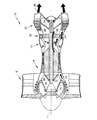
図1の典型的なガスタービンエンジン10の主なセクションは、前方から後方に向かって順に、低圧圧縮機12、高圧圧縮機14、燃焼器16、高圧タービン18、低圧タービン20からなり、長手方向の中心軸11の周囲にそれぞれ配設されている。作動流体22は、圧縮機12,14から後方に、燃焼器16内に送られ、そこで燃料が噴射され、混合気が燃焼される。高温の燃焼ガス24は、燃焼器16から流出し、環状ダクト26内で膨張して、タービン18,20を駆動する。次いで、タービン18,20は、高ロータスプール32および低ロータスプール34をそれぞれ形成する同心のシャフト28,30を介して結合された圧縮機14、12を駆動する。図では二重スプールのエンジン10が示されているが、三重スプールのエンジン10であってもよい。燃焼ガスは、航空機またはフリータービンに動力を供給するために使用される推力36としてエンジン10から流出する。作動流体22の一部分は、圧縮機12,14から抽気され、冷却空気38として燃焼器16の径方向内側かつ軸方向後方に向けてタービン18,20に送られる。
The main section of the typical
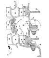
図2〜図4の例示的な低圧タービン20では、燃焼ガス24は、径方向外側の流路42および径方向内側の流路44によって画定された環状ダクト40を通って後方に導かれる。環状ダクト40内には、ロータブレード段50a〜50eおよびステータベーン段52a〜52dが交互に配設されている。ブレード50は、プラットフォーム58から径方向内側に配設されたルート部56によって、ロータディスク54から径方向外側に延びる。各ブレード50は、プラットフォーム58と外側先端シュラウド62との間で径方向に延びるエアフォイル60をさらに備える。エアフォイル60は、前方に面する前縁と、後方に面する後縁と、を有する。ブレード50は、ある例では、ディスク54から取外し可能であり、また他の例では、取外し可能ではない。ベーン52は、外側先端シュラウド62から径方向内側に延びるフック66によって、ケース64から内側に片持ち式に構成されている。各ベーン52は、内側シュラウド68と外側シュラウド70との間で径方向に延びるエアフォイル60を備える。
In the exemplary
外側シール72により、外側流路42における燃焼ガス24の漏出が制限される。外側シール72は、回転するロータブレード50と固定ケース64との間のインタフェース部分に配設される。先端シュラウド62は、半径方向外側に延びるランナ74を備え、このランナ74は、支持部78によってケース64に固定されかつ内側に面するランド76と径方向に協動する。ブレード50の回転とともに、ランナ74とランド76が径方向に協動することにより、ダム効果が生じて、燃焼ガス24の外側流路42からの漏出が制限される。重なり合ったプラットフォームおよびより高い圧力の冷却空気38の一定供給により、内側流路44における燃焼ガス24の漏出が制限される。
The outer seal 72 limits the leakage of the
圧縮機12,14から抽気された冷却空気38は、ボアキャビティ(bore cavity)80に向けて送られる。ボアキャビティ80は、隣接するディスクボア82によって軸方向に、また環状の連結部(カップリング)84によって径方向外側に境界が画定される。連結部84は、ボルト、リベット、溶接、ねじ、スプライン、テーパ、スナップばめ、または他の手段を用いて、隣接するディスク54を接合する。また、連結部84は、隣接するディスク82の各々と一体的に形成され得る(図示せず)。ディスク54の回転によって、冷却空気38が連結部84に対して径方向外側に送られる。冷却空気38は、連結部84の開口部86を通ってリムキャビティ88内に導かれる。開口部は、円形の穴、スロット、または他の形態であってもよく、典型的には、連結部84の周囲に亘って周方向に均等に配設される。開口部86は、適切な流量の冷却空気38をリムキャビティ88に流入させるサイズで形成される。
The cooling
リムキャビティ88内の冷却空気38は、全エンジン運転条件下で、環状ダクト40内の燃焼ガス24より高い圧力で維持される。より高い圧力の冷却空気38によって、燃焼ガス24がリムキャビティ88内に流入しないように防止され、ブレード50とベーン52との間のインタフェースが冷却される。冷却空気38の一部は、ブレードルート部56とディスク54との間に配設された複数のスロット90を通って軸方向後方に導かれる。冷却空気38の前記部分は、軸方向後方に向けて下流のリムキャビティ88に導かれる前に、ブレードルート部56とディスク54との間のインタフェースを冷却する。冷却空気38の他の部分は、径方向外側に導かれ、ブレード50とベーン52との間のインタフェース領域を冷却する。
The cooling
図3および図4に具体的に示されているように、本発明の様々な実施形態によるシール92により、ブレード50とベーン52との間のインタフェース部分において冷却空気38の漏出が制限される。ブレードプラットフォーム58は、1つまたは複数の周方向にセグメント化されたリング94を形成し、リング94は、ベーン52に固定されかつ内側に面するランド96と径方向に協動する。また、図4に具体的に示されているように、1つまたは複数の一体型リング94が、軸方向の長さに亘る任意の場所において連結部84から径方向外側に突出する。一体型リング94とランド96との協動により中間シールが形成され、該中間シールにより、キャビティ88が2つ以上のより小さなキャビティ88に分割される。この径方向外側に突出するリング94は、セグメント化されていないが、ベーン52に固定された内側に面するランド96と径方向に協動する。ブレード50の回転とともに、リング94とランド96の近接した径方向位置により、ダム効果が生じて、冷却空気38のリムキャビティ88からの漏出が制限する。
As specifically shown in FIGS. 3 and 4, the
ランド96は、一定の径方向の外形状を備えていてもよいし、燃焼ガス24のリムキャビティ88への流入をさらに防ぐように、径方向に階段状であってもよい。ランド96は、ろう付、溶接、または他の好適な手段によってベーン52に直接固定されてもよく、ベーン52から径方向内側に突出する支持部97に固定されてもよい。支持部97は、ベーン52と一体的であってもよいし、ろう付、溶接、または他の好適な手段によって固定されていてもよい。ランド96は、典型的には、ハニカム形状のシートメタル構造、または、漏出を制限するようにシールの技術分野において周知の他の構造および材料から構成されてもよい。
The
リング94は、ブレード50のプラットフォーム58から前縁方向、後縁方向、または両方向に軸方向に突出する。また、一体型リング94が連結部84から径方向に突出していてもよい。ブレード50がディスク54に組付けられると、個々のリング94セグメントが軸方向および径方向に整列して、中心軸11を中心にして実質的に完全なリング94が形成される。リング94は、ナイフエッジとして知られる1つまたは複数の径方向に延びるランナ98を備える。複数のランナ98を加えることにより、冷却空気38の漏出がさらに制限されるが、実際の数は、空間や重量の制限によって判断される。ランナ98の幅は、冷却空気38の速度を低減させるように、ランド96に隣接して、可能な限り薄いことが望ましい。ランナ98とランド96が断続的に接触することがあるため、通常、ランナ98にコーティング、耐摩耗加工、または他の耐摩耗処理が適用される。また、ランナ98は、セグメント化されたリング94の長手方向軸に対して、約22.5°〜約68°、好ましくは55°の角度(a)で傾斜していてもよい。ランナ98を冷却空気38の流れと反対の方向に傾斜させることにより、ダム効果が生じ、漏出がさらに制限される。また、ランナ98を傾斜させることにより、より厚いセグメント化されたリング94の長さが短くなり、重量がさらに減少する。リング94およびランナ98は、鋳造、従来の機械加工、放電加工、ケミカルミリング、または他の好適な製造方法によって形成される。
The
図5のブレード50の実施形態に示されるように、隣接するリング94のセグメントは、セグメント間の冷却空気38の漏出を低減させるように、機械的なシールエレメントを備えていてもよい。ブレード50が取付けられると、隣接するリング94セグメント間で舌部100と溝部102が協動し、冷却空気38の漏出が減少する。舌部100は、遠心負荷下で溝部102に完全に接触するように、径方向外側に傾斜していてもよい。リング94のセグメントの径方向の増加した厚さは、舌部100および溝部102を設けるためだけに必要であるため、通常、舌部100と溝部102の間に1つまたは複数のポケット104を配設し、ブレード50の回転質量を低減させる。ポケット104は、鋳造、従来の機械加工、放電加工、ケミカルミリング、または他の好適な製造方法によって形成される。
As shown in the
図6a〜図6gのリング94セグメントの実施形態に示されているように、隣接するリング94セグメントは、セグメント間の冷却空気38の漏出を低減させるように、空気力学的なシール手段を有する。一定量の冷却空気38および燃焼ガス24を、逆方向内側のポンプ機構を介して径方向内側に導くことにより、冷却空気38のリムキャビティ88から径方向外側への漏出が防止され、減少する。図6の各図では、ブレード50の基準の回転方向は、時計回りである。ブレード50の回転方向が反時計回りである場合、本発明の空気力学的シールエレメントは、エンジン10の長手方向軸11に沿って延びる平面で鏡映される。また、各図において、上流側リング194のセグメントを右側に図示し、下流側リング294を左側に図示している。
As shown in the
図6aは、面取りエッジ106、すなわち逆方向ポンプエレメントを示す。面取りエッジ106は、上流側リング194セグメントの正接方向に面している表面108と径方向外側の表面110との交差部分に位置している。一定量の冷却空気38および燃焼ガス24が面取りエッジ106と直面し、ブレード50の回転によって、隣接するリング194,294セグメント間から径方向内側に流入する。内側へのポンプ作用により、冷却空気38の径方向外側への漏出が防止される。
Figure 6a shows a
図6bは、二重の面取りエッジ106、すなわち逆方向のポンプエレメントを示す。面取りエッジ106は、上流側リング194セグメントの正接方向に面している表面108と径方向外側の表面110との交差部分に位置している。また、面取りエッジ106は、下流リング294セグメントの正接方向に面している表面108と径方向内側の表面112との交差部分に位置している。一定量の冷却空気38および燃焼ガス24が面取りエッジ106と直面し、ブレード50の回転によって、隣接するリング194,294セグメント間から径方向内側に流入する。内側へのポンプ作用により、冷却空気38の径方向外側への漏出が防止される。
Figure 6b shows a
図6cは、単一の傾斜付きエッジ114、すなわち逆方向のポンプエレメントを示す。傾斜付きエッジ114は、上流側リング194セグメントの径方向外側の表面110と径方向内側の表面112との間に位置する。一定量の冷却空気38および燃焼ガス24が傾斜付きエッジ114と直面し、ブレード50の回転によって、隣接するリング194,294セグメント間から径方向内側に流入する。内側へのポンプ作用により、冷却空気38の径方向外側への漏出が防止される。
Figure 6c shows a single
図6dは、二重の傾斜付きエッジ114、すなわち逆方向のポンプエレメントを示す。傾斜付きエッジ114は、上流側リング194セグメントの径方向外側の表面110と径方向内側の表面112との間に位置する。また、傾斜付きエッジ114は、下流リング194セグメントの径方向外側の表面110と径方向内側の表面112との間に位置する。一定量の冷却空気38および燃焼ガス24が傾斜付きエッジ114と直面し、ブレード50の回転によって、隣接するリング194,294セグメント間から径方向内側に流入する。内側へのポンプ作用により、冷却空気38の径方向外側への漏出が防止される。
FIG. 6d shows a double
図6eは、二重の正接方向で傾斜されたウィング116、すなわち逆方向のポンプエレメントを示す。径方向内側に傾斜したウィング116は、上流側リング194セグメントの正接方向に面する表面108に隣接して位置する。また、径方向外側に傾斜したウィング116は、下流側リング294セグメントの正接方向に面する表面108に隣接して位置する。一定量の冷却空気38および燃焼ガス24がウィング116と直面し、ブレード50の回転によって、隣接するリング194,294セグメント間から径方向内側に流入する。内側へのポンプ作用により、冷却空気38の径方向外側への漏出が防止される。
FIG. 6e shows a double tangentially
図6fは、単一の下流側ダム部118、すなわち逆方向のポンプエレメントを示す。下流側リング294セグメントの正接方向に面する表面108は、ダム部118を形成するように、上流側リング194セグメントの正接方向に面する表面108を越えて径方向外側に突出して径方向に厚くなっている。一定量の冷却空気38および燃焼ガス24がダム部118と直面し、ブレード50の回転によって、隣接するリング194,294セグメント間から径方向内側に流入する。内側へのポンプ作用により、冷却空気38の径方向外側への漏出が防止される。
Figure 6f shows a single
図6gは、二重のダム部118、すなわち逆方向のポンプエレメントを示す。下流側リング294セグメントの正接方向に面する表面108は、上流側リング194セグメントの正接方向で面する表面108を越えて、径方向外側に突出し径方向に厚くなっている。
また、上流側リング194セグメントの正接方向に面する表面108は、下流側リング294セグメントの正接方向で面する表面108を越えて、径方向内側に突出し、径方向に厚くなっている。一定量の冷却空気38および燃焼ガス24がダム部と直面し、ブレード50の回転によって、隣接するリング194,294セグメント間から径方向内側に流入する。内側へのポンプ作用により、冷却空気38の径方向外側への漏出が防止される。
FIG. 6g shows a
The
簡潔に説明するために、全図において低圧タービン20に関して図示しているが、高圧タービンおよび中圧タービンであってもよく、同様に例示的なシール92およびリムキャビティ88の冷却機構による利点がもたらされることを理解されたい。
For the sake of brevity, although shown with respect to the
本発明について、特定の実施形態について述べてきたが、当業者であれば、本願の記載を参照することによって他の代替形態、修正形態、変形形態が明らかになるであろう。したがって、代替形態、修正形態、変形形態が添付の特許請求の範囲の広い範囲内に包含される。 While the invention has been described with respect to particular embodiments, other alternatives, modifications and variations will become apparent to those skilled in the art upon reference to the description herein. Accordingly, alternatives, modifications and variations are encompassed within the broad scope of the appended claims.
Claims (40)
前記第1の段から軸方向に離間されるとともに、複数の外側に延びるブレードを備えた第2のロータ段と、
前記ロータ段の間に配設されるとともに、少なくとも1つの径方向内側に延びるランドを備えたベーン段と、
を備える段間シールであって、
前記ロータ段の各々が、前記ブレードから突出する少なくとも1つのリングを備え、
前記リングが、前記シールを形成するように前記少なくとも1つのランドと径方向に協動することを特徴とする段間シール。 A first rotor stage with a plurality of outwardly extending blades;
A second rotor stage that is axially spaced from the first stage and includes a plurality of outwardly extending blades;
A vane stage disposed between the rotor stages and having at least one radially inwardly extending land;
An interstage seal comprising:
Each of the rotor stages comprises at least one ring projecting from the blade;
An interstage seal, wherein the ring cooperates radially with the at least one land to form the seal.
前記ランドのうち第1のランドが、前記ランドの第2のランドより径方向内側に位置することを特徴とする請求項1に記載の段間シール。 The vane stage comprises two lands,
2. The interstage seal according to claim 1, wherein a first land of the lands is positioned radially inward from a second land of the lands.
隣接するリングセグメントが取付けられた際に、該隣接するリングセグメントの前記舌部および前記溝部が協動することを特徴とする請求項10に記載の段間シール。 Each segment of the ring comprises a tongue and a groove;
The interstage seal according to claim 10, wherein when the adjacent ring segments are attached, the tongue portion and the groove portion of the adjacent ring segment cooperate with each other.
前記取付部から径方向外側に配設されたプラットフォームと、
前記プラットフォームから径方向外側に延びるエアフォイルと、
前記プラットフォームから軸方向に突出する少なくとも1つのリングセグメントと、
を備えるタービンブレード。 A radially innermost attachment that engages the rotor;
A platform disposed radially outward from the mounting portion;
An airfoil extending radially outward from the platform;
At least one ring segment protruding axially from the platform;
A turbine blade comprising:
前記プラットフォームから前記前縁方向に第1のリングセグメントが突出し、前記プラットフォームから前記後縁方向に第2のリングセグメントが突出することを特徴とする請求項14に記載のタービンブレード。 The airfoil includes a front edge facing forward in the axial direction and a rear edge facing rearward in the axial direction,
The turbine blade according to claim 14, wherein a first ring segment protrudes from the platform toward the leading edge, and a second ring segment protrudes from the platform toward the trailing edge.
第1のディスクと、前記第1のディスクから径方向外側に延びる複数の第1のブレードと、を備える第1のロータ段と、
第2のディスクと、前記第2のディスクから径方向外側に延びる複数の第2のブレードと、を備える第2のロータ段であって、前記第1および第2のロータ段が該ロータ段の間にチャンバを形成するように離間され、前記第1および第2のディスクが、前記ブレードの径方向内側に配設された軸方向に延びる環状の連結部によって接合される第2のロータ段と、
前記第1および第2のロータ段の間に配設されるとともに、少なくとも1つの径方向内側に面するランドを備えるベーン段と、
前記第1および第2のブレードの各々から軸方向に突出するとともに、前記インタフェースシールを形成するように前記少なくとも1つのランドと径方向に協動するリングと、
前記連結部を貫通するとともに、前記シールの冷却に使用される冷却流体を前記チャンバに向けて径方向に導く開口部と、
を備えるガスタービンエンジンの冷却されるロータとステータとの間におけるインタフェースシール。 An interface seal between a cooled rotor and stator of a gas turbine engine,
A first rotor stage comprising: a first disk; and a plurality of first blades extending radially outward from the first disk;
A second rotor stage comprising a second disk and a plurality of second blades extending radially outward from the second disk, wherein the first and second rotor stages are of the rotor stage. A second rotor stage spaced apart so as to form a chamber therebetween, wherein the first and second disks are joined by an axially extending annular coupling disposed radially inward of the blade; ,
A vane stage disposed between the first and second rotor stages and comprising at least one radially inwardly facing land;
A ring projecting axially from each of the first and second blades and radially cooperating with the at least one land to form the interface seal;
An opening that penetrates the connecting portion and guides a cooling fluid used for cooling the seal in a radial direction toward the chamber;
An interface seal between a cooled rotor and a stator of a gas turbine engine comprising:
前記リングが、前記シールの一部を形成するように前記少なくとも1つのランドと径方向に協動することを特徴とする請求項25に記載のインタフェースシール。 The connecting portion further includes a ring protruding radially outward;
26. The interface seal of claim 25, wherein the ring cooperates radially with the at least one land to form a portion of the seal.
Applications Claiming Priority (1)
| Application Number | Priority Date | Filing Date | Title |
|---|---|---|---|
| US11/260,357 US7334983B2 (en) | 2005-10-27 | 2005-10-27 | Integrated bladed fluid seal |
Publications (1)
| Publication Number | Publication Date |
|---|---|
| JP2007120501A true JP2007120501A (en) | 2007-05-17 |
Family
ID=37776593
Family Applications (1)
| Application Number | Title | Priority Date | Filing Date |
|---|---|---|---|
| JP2006290590A Pending JP2007120501A (en) | 2005-10-27 | 2006-10-26 | Interstage seal, turbine blade, and interface seal between cooled rotor and stator of gas turbine engine |
Country Status (4)
| Country | Link |
|---|---|
| US (1) | US7334983B2 (en) |
| EP (1) | EP1780380B1 (en) |
| JP (1) | JP2007120501A (en) |
| CA (1) | CA2564073A1 (en) |
Cited By (5)
| Publication number | Priority date | Publication date | Assignee | Title |
|---|---|---|---|---|
| JP2010077869A (en) * | 2008-09-25 | 2010-04-08 | Mitsubishi Heavy Ind Ltd | Rim seal structure of gas turbine |
| JP2011515610A (en) * | 2008-03-19 | 2011-05-19 | スネクマ | Sectorized distributor for turbomachinery. |
| JP2012163094A (en) * | 2010-12-21 | 2012-08-30 | Avio Spa | Gas turbine for aircraft engine |
| JP2013177892A (en) * | 2012-02-28 | 2013-09-09 | General Electric Co <Ge> | Seal for rotary device and method of producing the same |
| TWI409383B (en) * | 2007-09-24 | 2013-09-21 | Alstom Technology Ltd | Seal in gas turbine |
Families Citing this family (41)
| Publication number | Priority date | Publication date | Assignee | Title |
|---|---|---|---|---|
| JP2006097585A (en) * | 2004-09-29 | 2006-04-13 | Mitsubishi Heavy Ind Ltd | Mounting structure for air separator and gas turbine provided with the same |
| US7500824B2 (en) * | 2006-08-22 | 2009-03-10 | General Electric Company | Angel wing abradable seal and sealing method |
| US7708520B2 (en) * | 2006-11-29 | 2010-05-04 | United Technologies Corporation | Gas turbine engine with concave pocket with knife edge seal |
| US8128371B2 (en) * | 2007-02-15 | 2012-03-06 | General Electric Company | Method and apparatus to facilitate increasing turbine rotor efficiency |
| US8167547B2 (en) | 2007-03-05 | 2012-05-01 | United Technologies Corporation | Gas turbine engine with canted pocket and canted knife edge seal |
| US7918265B2 (en) | 2008-02-14 | 2011-04-05 | United Technologies Corporation | Method and apparatus for as-cast seal on turbine blades |
| DE102008014743A1 (en) * | 2008-03-18 | 2009-09-24 | Rolls-Royce Deutschland Ltd & Co Kg | Compressor stator with partial cover tape |
| US20090238683A1 (en) * | 2008-03-24 | 2009-09-24 | United Technologies Corporation | Vane with integral inner air seal |
| GB2467350A (en) * | 2009-02-02 | 2010-08-04 | Rolls Royce Plc | Cooling and sealing in gas turbine engine turbine stage |
| DE102009007664A1 (en) * | 2009-02-05 | 2010-08-12 | Mtu Aero Engines Gmbh | Sealing device on the blade shank of a rotor stage of an axial flow machine |
| US8282346B2 (en) * | 2009-04-06 | 2012-10-09 | General Electric Company | Methods, systems and/or apparatus relating to seals for turbine engines |
| US8888459B2 (en) * | 2011-08-23 | 2014-11-18 | General Electric Company | Coupled blade platforms and methods of sealing |
| US9115591B2 (en) | 2011-08-30 | 2015-08-25 | United Technologies Corporation | Universal seal |
| US8926269B2 (en) | 2011-09-06 | 2015-01-06 | General Electric Company | Stepped, conical honeycomb seal carrier |
| US9175575B2 (en) * | 2012-01-04 | 2015-11-03 | General Electric Company | Modification of turbine engine seal abradability |
| US9416673B2 (en) * | 2012-01-17 | 2016-08-16 | United Technologies Corporation | Hybrid inner air seal for gas turbine engines |
| US9017013B2 (en) | 2012-02-07 | 2015-04-28 | Siemens Aktiengesellschaft | Gas turbine engine with improved cooling between turbine rotor disk elements |
| US9175567B2 (en) * | 2012-02-29 | 2015-11-03 | United Technologies Corporation | Low loss airfoil platform trailing edge |
| US9181815B2 (en) | 2012-05-02 | 2015-11-10 | United Technologies Corporation | Shaped rim cavity wing surface |
| US10094389B2 (en) * | 2012-12-29 | 2018-10-09 | United Technologies Corporation | Flow diverter to redirect secondary flow |
| US10053998B2 (en) * | 2012-12-29 | 2018-08-21 | United Technologies Corporation | Multi-purpose gas turbine seal support and assembly |
| WO2015017040A2 (en) | 2013-07-30 | 2015-02-05 | United Technologies Corporation | Gas turbine engine vane ring arrangement |
| US10287905B2 (en) * | 2013-11-11 | 2019-05-14 | United Technologies Corporation | Segmented seal for gas turbine engine |
| US9771802B2 (en) | 2014-02-25 | 2017-09-26 | Siemens Energy, Inc. | Thermal shields for gas turbine rotor |
| KR101833660B1 (en) * | 2014-04-03 | 2018-02-28 | 미츠비시 히타치 파워 시스템즈 가부시키가이샤 | Vane array and gas turbine |
| US20160230579A1 (en) * | 2015-02-06 | 2016-08-11 | United Technologies Corporation | Rotor disk sealing and blade attachments system |
| US10030582B2 (en) | 2015-02-09 | 2018-07-24 | United Technologies Corporation | Orientation feature for swirler tube |
| US10337345B2 (en) | 2015-02-20 | 2019-07-02 | General Electric Company | Bucket mounted multi-stage turbine interstage seal and method of assembly |
| FR3040461B1 (en) * | 2015-09-02 | 2018-02-23 | Safran Aircraft Engines | LABYRINTH SEALING ELEMENT FOR TURBINE |
| US10060280B2 (en) * | 2015-10-15 | 2018-08-28 | United Technologies Corporation | Turbine cavity sealing assembly |
| US10240461B2 (en) | 2016-01-08 | 2019-03-26 | General Electric Company | Stator rim for a turbine engine |
| US10316681B2 (en) * | 2016-05-31 | 2019-06-11 | General Electric Company | System and method for domestic bleed circuit seals within a turbine |
| US10428661B2 (en) * | 2016-10-26 | 2019-10-01 | Roll-Royce North American Technologies Inc. | Turbine wheel assembly with ceramic matrix composite components |
| DE102017108581A1 (en) * | 2017-04-21 | 2018-10-25 | Rolls-Royce Deutschland Ltd & Co Kg | Turbomachine with an adaptive sealing device |
| US10480333B2 (en) * | 2017-05-30 | 2019-11-19 | United Technologies Corporation | Turbine blade including balanced mateface condition |
| US10329938B2 (en) * | 2017-05-31 | 2019-06-25 | General Electric Company | Aspirating face seal starter tooth abradable pocket |
| US10669877B2 (en) * | 2017-12-21 | 2020-06-02 | United Technologies Corporation | Air seal attachment |
| FR3085412B1 (en) * | 2018-08-31 | 2020-12-04 | Safran Aircraft Engines | TURBOMACHINE DISTRIBUTOR AREA INCLUDING AN ANTI-ROTATION NOTCH WITH WEAR INSERT |
| GB202001689D0 (en) * | 2020-02-07 | 2020-03-25 | Rolls Royce Plc | Rotor assembly |
| FR3107312B1 (en) * | 2020-02-13 | 2022-11-18 | Safran Aircraft Engines | Rotary assembly for turbomachine |
| GB202005789D0 (en) | 2020-03-03 | 2020-06-03 | Itp Next Generation Turbines S L U | Blade assembly for gas turbine engine |
Family Cites Families (14)
| Publication number | Priority date | Publication date | Assignee | Title |
|---|---|---|---|---|
| GB1318654A (en) * | 1970-12-05 | 1973-05-31 | Secr Defence | Bladed rotors |
| US4103899A (en) * | 1975-10-01 | 1978-08-01 | United Technologies Corporation | Rotary seal with pressurized air directed at fluid approaching the seal |
| US4669959A (en) * | 1984-07-23 | 1987-06-02 | United Technologies Corporation | Breach lock anti-rotation key |
| US4820116A (en) * | 1987-09-18 | 1989-04-11 | United Technologies Corporation | Turbine cooling for gas turbine engine |
| JPH10252412A (en) * | 1997-03-12 | 1998-09-22 | Mitsubishi Heavy Ind Ltd | Gas turbine sealing device |
| US6220814B1 (en) * | 1998-07-16 | 2001-04-24 | Siemens Westinghouse Power Corporation | Turbine interstage sealing arrangement |
| JP2000034902A (en) * | 1998-07-17 | 2000-02-02 | Mitsubishi Heavy Ind Ltd | Cooling rotor blade for gas turbine |
| EP1018594B1 (en) * | 1999-01-06 | 2006-12-27 | General Electric Company | Wheelspace windage cover plate for a turbine |
| US6428270B1 (en) * | 2000-09-15 | 2002-08-06 | General Electric Company | Stage 3 bucket shank bypass holes and related method |
| WO2003052240A2 (en) * | 2001-12-14 | 2003-06-26 | Alstom Technology Ltd | Gas turbine system |
| JP2004011580A (en) * | 2002-06-10 | 2004-01-15 | Toshiba Corp | Gas turbine rotor |
| DE10318852A1 (en) | 2003-04-25 | 2004-11-11 | Rolls-Royce Deutschland Ltd & Co Kg | Main gas duct inner seal of a high pressure turbine |
| US6899520B2 (en) | 2003-09-02 | 2005-05-31 | General Electric Company | Methods and apparatus to reduce seal rubbing within gas turbine engines |
| FR2895021B1 (en) * | 2005-12-16 | 2010-09-03 | Snecma | INTER-STAGE SEALING SYSTEM IN A TURBOMACHINE |
-
2005
- 2005-10-27 US US11/260,357 patent/US7334983B2/en active Active
-
2006
- 2006-10-13 CA CA002564073A patent/CA2564073A1/en not_active Abandoned
- 2006-10-26 JP JP2006290590A patent/JP2007120501A/en active Pending
- 2006-10-26 EP EP06255507.3A patent/EP1780380B1/en active Active
Cited By (5)
| Publication number | Priority date | Publication date | Assignee | Title |
|---|---|---|---|---|
| TWI409383B (en) * | 2007-09-24 | 2013-09-21 | Alstom Technology Ltd | Seal in gas turbine |
| JP2011515610A (en) * | 2008-03-19 | 2011-05-19 | スネクマ | Sectorized distributor for turbomachinery. |
| JP2010077869A (en) * | 2008-09-25 | 2010-04-08 | Mitsubishi Heavy Ind Ltd | Rim seal structure of gas turbine |
| JP2012163094A (en) * | 2010-12-21 | 2012-08-30 | Avio Spa | Gas turbine for aircraft engine |
| JP2013177892A (en) * | 2012-02-28 | 2013-09-09 | General Electric Co <Ge> | Seal for rotary device and method of producing the same |
Also Published As
| Publication number | Publication date |
|---|---|
| EP1780380B1 (en) | 2017-11-29 |
| US20070098545A1 (en) | 2007-05-03 |
| EP1780380A2 (en) | 2007-05-02 |
| EP1780380A3 (en) | 2011-07-20 |
| CA2564073A1 (en) | 2007-04-27 |
| US7334983B2 (en) | 2008-02-26 |
Similar Documents
| Publication | Publication Date | Title |
|---|---|---|
| JP2007120501A (en) | Interstage seal, turbine blade, and interface seal between cooled rotor and stator of gas turbine engine | |
| US4425079A (en) | Air sealing for turbomachines | |
| US8419356B2 (en) | Turbine seal assembly | |
| US8087249B2 (en) | Turbine cooling air from a centrifugal compressor | |
| EP1211386B1 (en) | Turbine interstage sealing ring and corresponding turbine | |
| US5215435A (en) | Angled cooling air bypass slots in honeycomb seals | |
| EP2239422B1 (en) | Sealing arrangement for a gas turbine engine | |
| US7775764B2 (en) | Gas turbine engine rotor ventilation arrangement | |
| JP4746325B2 (en) | Gas turbine engine component having a bypass circuit | |
| JP6031116B2 (en) | Asymmetric radial spline seals for gas turbine engines | |
| US8834122B2 (en) | Turbine bucket angel wing features for forward cavity flow control and related method | |
| JP2006342797A (en) | Seal assembly of gas turbine engine, rotor assembly, blade for rotor assembly and inter-stage cavity seal | |
| JP2006342796A (en) | Seal assembly of gas turbine engine, rotor assembly and blade for rotor assembly | |
| CN108798804B (en) | Spline for turbine engine | |
| JP2004076726A (en) | Bleeding case for compressor | |
| US8827643B2 (en) | Turbine bucket platform leading edge scalloping for performance and secondary flow and related method | |
| CN110325711B (en) | Spline of turbine engine | |
| US8312729B2 (en) | Flow discouraging systems and gas turbine engines | |
| US20130004319A1 (en) | Rotor assembly and reversible turbine blade retainer therefor | |
| CA2906895A1 (en) | Turbine shroud sealing architecture | |
| US10539035B2 (en) | Compliant rotatable inter-stage turbine seal | |
| US20170175557A1 (en) | Gas turbine sealing | |
| US6129513A (en) | Fluid seal | |
| JP5400500B2 (en) | Labyrinth seal for turbine dovetail | |
| US11098605B2 (en) | Rim seal arrangement |