EP1780380A2 - Gas turbine blade to vane interface seal - Google Patents
Gas turbine blade to vane interface seal Download PDFInfo
- Publication number
- EP1780380A2 EP1780380A2 EP06255507A EP06255507A EP1780380A2 EP 1780380 A2 EP1780380 A2 EP 1780380A2 EP 06255507 A EP06255507 A EP 06255507A EP 06255507 A EP06255507 A EP 06255507A EP 1780380 A2 EP1780380 A2 EP 1780380A2
- Authority
- EP
- European Patent Office
- Prior art keywords
- ring
- seal
- radially
- blade
- blades
- Prior art date
- Legal status (The legal status is an assumption and is not a legal conclusion. Google has not performed a legal analysis and makes no representation as to the accuracy of the status listed.)
- Granted
Links
Images


Classifications
-
- F—MECHANICAL ENGINEERING; LIGHTING; HEATING; WEAPONS; BLASTING
- F01—MACHINES OR ENGINES IN GENERAL; ENGINE PLANTS IN GENERAL; STEAM ENGINES
- F01D—NON-POSITIVE DISPLACEMENT MACHINES OR ENGINES, e.g. STEAM TURBINES
- F01D11/00—Preventing or minimising internal leakage of working-fluid, e.g. between stages
- F01D11/02—Preventing or minimising internal leakage of working-fluid, e.g. between stages by non-contact sealings, e.g. of labyrinth type
-
- F—MECHANICAL ENGINEERING; LIGHTING; HEATING; WEAPONS; BLASTING
- F01—MACHINES OR ENGINES IN GENERAL; ENGINE PLANTS IN GENERAL; STEAM ENGINES
- F01D—NON-POSITIVE DISPLACEMENT MACHINES OR ENGINES, e.g. STEAM TURBINES
- F01D11/00—Preventing or minimising internal leakage of working-fluid, e.g. between stages
- F01D11/001—Preventing or minimising internal leakage of working-fluid, e.g. between stages for sealing space between stator blade and rotor
-
- F—MECHANICAL ENGINEERING; LIGHTING; HEATING; WEAPONS; BLASTING
- F01—MACHINES OR ENGINES IN GENERAL; ENGINE PLANTS IN GENERAL; STEAM ENGINES
- F01D—NON-POSITIVE DISPLACEMENT MACHINES OR ENGINES, e.g. STEAM TURBINES
- F01D5/00—Blades; Blade-carrying members; Heating, heat-insulating, cooling or antivibration means on the blades or the members
- F01D5/02—Blade-carrying members, e.g. rotors
- F01D5/08—Heating, heat-insulating or cooling means
- F01D5/081—Cooling fluid being directed on the side of the rotor disc or at the roots of the blades
-
- F—MECHANICAL ENGINEERING; LIGHTING; HEATING; WEAPONS; BLASTING
- F02—COMBUSTION ENGINES; HOT-GAS OR COMBUSTION-PRODUCT ENGINE PLANTS
- F02C—GAS-TURBINE PLANTS; AIR INTAKES FOR JET-PROPULSION PLANTS; CONTROLLING FUEL SUPPLY IN AIR-BREATHING JET-PROPULSION PLANTS
- F02C7/00—Features, components parts, details or accessories, not provided for in, or of interest apart form groups F02C1/00 - F02C6/00; Air intakes for jet-propulsion plants
- F02C7/28—Arrangement of seals
-
- Y—GENERAL TAGGING OF NEW TECHNOLOGICAL DEVELOPMENTS; GENERAL TAGGING OF CROSS-SECTIONAL TECHNOLOGIES SPANNING OVER SEVERAL SECTIONS OF THE IPC; TECHNICAL SUBJECTS COVERED BY FORMER USPC CROSS-REFERENCE ART COLLECTIONS [XRACs] AND DIGESTS
- Y02—TECHNOLOGIES OR APPLICATIONS FOR MITIGATION OR ADAPTATION AGAINST CLIMATE CHANGE
- Y02T—CLIMATE CHANGE MITIGATION TECHNOLOGIES RELATED TO TRANSPORTATION
- Y02T50/00—Aeronautics or air transport
- Y02T50/60—Efficient propulsion technologies, e.g. for aircraft
Definitions
- the invention relates to gas turbine engines, and more specifically to a cooled fluid sealing arrangement disposed between blades and vanes of such engines.
- Gas turbine engines operate by compressing ambient air with a forward compressor, injecting a fuel, burning the air-fuel mixture in a central combustor and converting the energy of combustion into a propulsive force.
- Combustion gases exit the combustor through an annular duct, where the gases drive one or more axial stages of circumferentially distributed turbine blades.
- Each bladed stage transfers the combustion gas energy to a rotor attached to a central, longitudinal shaft.
- Interposed with the rotating blade stages are stationary vane stages affixed to radially outer casing structures, circumscribing the rotor. Two or more rotors may operate independently of one another and at differing speeds via concentric shafts.
- Gas turbine engines are flexible power plants that are typically used for powering aircraft, ships and generators.
- turbine components such as blades, vanes and seals are cooled with lower-temperature, higher-pressure cooling air.
- the cooling air is bled from the compressors, then directed axially rearward and radially inward of the rotors to the turbine components, bypassing the combustor altogether.
- Once delivered to the turbine a significant portion of the cooling air is directed radially outward to the blades, vanes and seals by the centrifugal force of the turning rotors.
- the interfaces of the rotating blade stages and stationary vane stages must be effectively sealed.
- the interfaces of the rotating blade stages and stationary vane stages are particularly difficult to seal due to the differences in thermal and centrifugal growth between the rotors and the cases.
- the high relative speeds, extremely high temperatures and pressures also present seal design challenges in the turbines.
- designers have attempted to seal the interfaces of the rotating blade stages and stationary vane stages with varying degrees of success.
- a labyrinth seal In a typical blade to vane interface, a multi-step labyrinth seal, comprising stationary lands and rotating runners or knife-edges, restricts leakage of the cooling air radially outward, into the combustion gases.
- the runners project from annular supports, which are typically fastened to the rotor with bolted flanges and/or with snap fits.
- the supports are independent components, adding to the manufacturing costs and complexity of the turbine.
- the supports also contribute additional rotational mass to the rotors, which reduces the engine-operating efficiency.
- the attachments at the interfaces of the supports and the rotors create an additional leakage path for the cooling air. Placement of the supports is influenced by adjacent components and typically does not optimize the distribution of the cooling air.
- rotor to stator interface seals for restricting leakage of cooling air and improving the apportioning of the cooling air to the seals.
- a turbine rotor contains a first and a second stage of circumferentially distributed blades.
- the blade stages are separated axially from one another by an annular coupling located radially inboard of the blades, forming a chamber therebetween.
- Interposed between the blade stages is a stationary vane stage.
- the vane stage contains a land, facing radially inwardly.
- a ring projects axially from each of the first and second blade stages towards the vane stage. The rings radially cooperate with the land and together form the blade to vane interface seal.
- the coupling contains an aperture for radially introducing cooling air to the chamber for use in cooling the seal.
- a turbine rotor in another embodiment of an interface seal in accordance with the present invention, contains a first and a second stage of circumferentially distributed blades.
- the blade stages are separated axially from one another by an annular coupling located radially inboard of the blades, forming a chamber therebetween.
- Interposed between the blade stages is a stationary vane stage.
- the vane stage contains a radially inwardly facing land.
- a ring projects axially from blade stages towards the vane stage.
- the rings radially cooperate with the land.
- the coupling contains an integral ring projecting radially outward and radially cooperating with the land. Together, the cooperating rings and land form the blade to vane interface seal.
- the coupling also contains an aperture for radially introducing cooling air to the chamber for use in cooling the seal. Although the aperture may be located anywhere along the axial length of the coupling, it is typically located forward of the vane stage.
- sealing rings are integral with the existing blades and couplings of the gas turbine engine, separate supports are not needed and are therefore eliminated.
- the elimination of separate supports reduces the rotational mass of the rotors, thus improving engine-operating efficiency. Also, by relocating the rings to the blades, cooling air leakage paths are eliminated and the cooling air apportioning to the seal is improved.
- the major sections of a typical gas turbine engine 10 of FIG. 1 include in series, from front to rear and disposed about a central longitudinal axis 11, a low-pressure compressor 12, a high-pressure compressor 14, a combustor 16, a high-pressure turbine 18 and a low-pressure turbine 20.
- a working fluid 22 is directed rearward through the compressors 12, 14 and into the combustor 16, where fuel is injected and the mixture is burned.
- Hot combustion gases 24 exit the combustor 16 and expand within an annular duct 26, driving the turbines 18, 20.
- the turbines 18, 20, in turn drive coupled compressors 14, 12 via concentric shafts 28, 30, forming a high rotor spool 32 and a low rotor spool 34 respectively.
- a dual spool engine 10 is depicted in the figure, three spool engines 10 are not uncommon.
- the combustion gases exit the engine 10 as a propulsive thrust 36, used to power an aircraft or a free turbine.
- a portion of the working fluid 22 is bled from the compressors 12, 14 and is directed radially inward of the combustor 16 and axially rearward to the turbines 18, 20 for use as cooling air 38.
- the combustion gases 24 are directed rearward through an annular duct 40 approximately defined by a radially outer flow path 42 and a radially inner flow path 44. Disposed circumferentially within the annular duct 40 are alternating stages of rotating blades 50a-50e and stationary vanes 52a-52d.
- the blades 50 extend radially outward from a rotor disk 54 by roots 56 disposed radially inward of platforms 58.
- Each blade 50 further comprises an airfoil 60, extending radially between the platform 58 and an outer tip shroud 62.
- the airfoil 60 has a forward facing leading edge and a rearward facing trailing edge.
- the blades 50 are removable from the disks 54 and in some instances non-removable.
- the vanes 52 are cantilevered inward from a case 64 by hooks 66 extending radially outward from the outer tip shrouds 62.
- Each vane 52 comprises an airfoil 60 that extends radially between an inner shroud 68 and an outer shroud 70.
- Outer seals 72 restrict leakage of the combustion gases 74 at the outer flow path 42.
- the outer seals 72 are disposed at the interface of the rotating blades 50 and the stationary case 64.
- the tip shrouds 62 contain outwardly extending runners 74 that radially cooperate with inwardly facing lands 76 affixed to the case 64 by supports 78. The radial cooperation of the runners 74 and the lands 76, along with the rotation of the blades 50, cause a damming effect and thus restricts leakage of the combustion gases 24 from the outer flow path 42.
- Overlapping platforms 58 and a constant supply of higher pressure cooling air 38 restrict leakage of the combustion gases 24 at the inner flow path 44.
- Cooling air 38, bled from the compressors 12,14 is directed to bore cavities 80.
- the bore cavities 80 are bounded axially by adjacent disk bores 82 and radially outwardly by an annular coupling 84.
- the coupling 84 joins adjacent disks 54 with bolts, rivets, welds, threads, splines, tapers, snap fits, or other means.
- the coupling 84 may also be integrally formed with each of the adjacent disks 82 (not shown).
- the cooling air 38 is pumped radially outward, against the couplings 84, by the rotation of the disks 54.
- Apertures 86 in the couplings 84 direct the cooling air 38 into rim cavities 88.
- the apertures may be circular holes, slots, or other forms and are typically, evenly distributed cirumferentially about the coupling 84.
- the apertures 86 are sized to allow the appropriate cooling air 38 volume to enter the rim cavity 88.
- the cooling air 38 inside the rim cavity 88 is maintained at a higher pressure than the combustion gases 24 in the annular duct 40 under all engine-operating conditions.
- the higher pressure cooling air 38 prevents combustion gas 24 ingestion into the rim cavities 88 and provides cooling for the blade 50 to vane 52 interface.
- a portion of the cooling air 38 is directed axially rearward through a plurality of slots 90 disposed between the blade roots 56 and the disk 54. This portion of cooling air 38 reduces the temperature of the blade root 56 to disk 54 interface before being directed axially rearward to a downstream rim cavity 88.
- Another portion of the cooling air 38 is directed radially outward to cool the blade 50 to vane 52 interface region.
- seals 92 restrict the leakage of the cooling air 38 at the interfaces of the blades 50 and vanes 52.
- the blade platforms 58 form one or more circumferentially segmented rings 94 that radially cooperate with inwardly facing lands 96 affixed to the vanes 52.
- one or more integral rings 94 may project radially outward from coupling 84 anywhere along its axial length as specifically illustrated in FIG. 4. The cooperation of the integral rings 94 and lands 96 form intermediate seals, which partition cavity 88 into two or more smaller cavities 88.
- the radially outward projecting ring 94 is not segmented and also radially cooperates with a land 96 affixed to a vane 52.
- the lands 96 may have a constant radial profile or may be stepped radially to further prevent ingestion of the combustion gases 24 into the rim cavity 88.
- a land 96 may be affixed directly to the vane 52 by brazing, welding or other suitable means or may be affixed to a support 97 projecting radially inwardly from the vane 52.
- the support 97 may be integrated with the vane 52 or may be affixed by brazing, welding or other suitable means.
- a land 96 is typically comprised of a honeycomb shaped, sheet metal structure, or any other structure and material known in the sealing art to restrict leakage.
- the rings 94 project axially from a platform 58 of a blade 50 in a leading edge direction, a trailing edge direction, or both directions.
- An integral ring 94 may also project radially from coupling 84. With the blades 50 assembled into a disk 54, individual ring 94 segments axially and radially align, to form a substantially complete ring 94 about central axis 11.
- a ring 94 may contain one or more radially extending runners 98, which are also known as knife-edges. The addition of multiple runners 98 provides a greater cooling air 38 leakage restriction, but the actual number may be dictated by space and/or weight limitations.
- the width of a runner 98 should be as thin as possible, adjacent to a land 96, to reduce the velocity of any cooling air 38 flowing therebetween. Since intermittent contact between a runner 98 and a land 96 may occur, a coating, hardface or other wear-resistant treatment is typically applied to the runners 98.
- a runner 98 may also be canted at an angle (•) from between about 22.5 degrees to about 68 degrees, preferably 55 degrees, relative to the longitudinal axis of the segmented ring 94. By canting the runner 98 in the direction opposing the cooling air 38 flow, a damming effect is created, providing for an increased leakage restriction.
- Canting a runner 98 also reduces the length of the thicker, segmented ring 94, reducing weight even further.
- the rings 94 and runners 98 are formed by casting, conventional machining, electrodischarge machining, chemical milling, or any other suitable manufacturing methods.
- adjacent ring 94 segments may contain mechanical sealing elements to reduce leakage of cooling air 38 therebetween.
- a tongue 100 and a groove 102 cooperate between adjacent ring 94 segments to reduce leakage of the cooling air 38.
- the tongue 100 may be inclined radially outward to ensure it completely contacts the groove 102 under centrifugal loading. Since an increased radial thickness of the ring 94 segment is only required to accommodate the tongue 100 and groove 102, one or more pockets 104 are typically located between the tongue 100 and groove 102 to reduce the rotational mass of the blade 50.
- the pockets 104 are formed by casting, conventional machining, electrodischarge machining, chemical milling or any other suitable manufacturing methods.
- adjacent ring 94 segments may contain aerodynamic sealing means to reduce leakage of cooling air 38 therebetween.
- aerodynamic sealing means to reduce leakage of cooling air 38 therebetween.
- the reference rotation of the blades 50 is in the clockwise direction. If the rotation of the blades 50 is in the counterclockwise direction, the inventive aerodynamic sealing elements are mirrored about a plane extending through the longitudinal axis 11 of the engine 10.
- the upstream ring 194 segment is illustrated to the right and the downstream ring 294 segment is illustrated to the left in each of the figures.
- FIG. 6a illustrates a chamfered edge 106, reverse pumping element.
- the chamfered edge 106 is located at the intersection of a tangentially facing surface 108 and a radially outer surface 110 of the upstream ring 194 segment.
- a volume of cooling air 38 and combustion gases 24 encounters the chamfered edge 106 and is pumped radially inward, between adjacent ring 194, 294 segments, by the rotation of the blades 50.
- the inward pumping opposes the radially outward leakage of cooling air 38.
- FIG. 6b illustrates a double chamfered edge 106, reverse pumping element.
- a chamfered edge 106 is located at the intersection of a tangentially facing surface 108 and a radially outer surface 110 of the upstream ring 194 segment.
- a chamfered edge 106 is located at the intersection of a tangentially facing surface 108 and a radially inner surface 112 of the downstream ring 294 segment.
- a volume of cooling air 38 and combustion gases 24 encounters the chamfered edges 106 and is pumped radially inward, between adjacent ring 194, 294 segments, by the rotation of the blades 50. The inward pumping opposes the radially outward leakage of cooling air 38.
- FIG. 6c illustrates a single sloped edge 114, reverse pumping element.
- a sloped edge 114 is located between a radially outer surface 110 and a radially inner surface 112 of the upstream ring 194 segment.
- a volume of cooling air 38 and combustion gases 24 encounters the sloped edge 114 and is pumped radially inward, between adjacent ring 194, 294 segments, by the rotation of the blades 50. The inward pumping opposes the radially outward leakage of cooling air 38.
- FIG. 6d illustrates a dual sloped edge 114, reverse pumping element.
- a sloped edge 114 is located between a radially outer surface 110 and a radially inner surface 112 of the upstream ring 194 segment. Also, a sloped edge 114 is located between a radially outer surface 110 and a radially inner surface 112 of the downstream ring 194 segment.
- a volume of cooling air 38 and combustion gases 24 encounters the sloped edges 114 and is pumped radially inward, between adjacent ring 194, 294 segments, by the rotation of the blades 50. The inward pumping opposes the radially outward leakage of cooling air 38.
- FIG. 6e illustrates a dual tangentially sloped wing 116, reverse pumping element.
- a radially inner sloped wing 116 is located adjacent the tangentially facing surface 108 of the upstream ring 194 segment.
- a radially outer sloped wing 116 is located adjacent the tangentially facing surface 108 of the downstream ring 294 segment.
- a volume of cooling air 38 and combustion gases 24 encounters the wings 116 and is pumped radially inward, between adjacent ring 194, 294 segments, by the rotation of the blades 50. The inward pumping opposes the radially outward leakage of cooling air 38.
- FIG. 6f illustrates a single downstream dam 118, reverse pumping element.
- the tangentially facing surface 108 of the downstream ring 294 segment is radially thickened and protrudes radially outward, beyond the tangentially facing surface 108 of the upstream ring 194 segment to form the dam 118.
- a volume of cooling air 38 and combustion gases 24 encounters the dam 118 and is pumped radially inward, between adjacent ring 194, 294 segments, by the rotation of the blades 50. The inward pumping opposes the radially outward leakage of cooling air 38.
- FIG. 6g illustrates a dual dam 118, reverse pumping feature.
- the tangentially facing surface 108 of the downstream ring 294 segment is radially thickened and protrudes radially outward, beyond the tangentially facing surface 108 of the upstream ring 194 segment.
- the tangentially facing surface 108 of the upstream ring 194 segment is radially thickened and protrudes radially inward, beyond the tangentially facing surface 108 of the downstream ring 294 segment.
- a volume of cooling air 38 and combustion gases 24 encounters the dam and is pumped radially inward, between adjacent ring 194, 294 segments, by the rotation of the blades 50. The inward pumping opposes the radially outward leakage of cooling air 38.
Abstract
Description
- The invention relates to gas turbine engines, and more specifically to a cooled fluid sealing arrangement disposed between blades and vanes of such engines.
- Gas turbine engines operate by compressing ambient air with a forward compressor, injecting a fuel, burning the air-fuel mixture in a central combustor and converting the energy of combustion into a propulsive force. Combustion gases exit the combustor through an annular duct, where the gases drive one or more axial stages of circumferentially distributed turbine blades. Each bladed stage transfers the combustion gas energy to a rotor attached to a central, longitudinal shaft. Interposed with the rotating blade stages are stationary vane stages affixed to radially outer casing structures, circumscribing the rotor. Two or more rotors may operate independently of one another and at differing speeds via concentric shafts. Gas turbine engines are flexible power plants that are typically used for powering aircraft, ships and generators.
- In order to withstand combustion gas temperatures that regularly exceed 2000 degrees Fahrenheit (1093°C) and pressures exceeding 400 pounds per square inch (2.76 MPa) absolute, turbine components such as blades, vanes and seals are cooled with lower-temperature, higher-pressure cooling air. The cooling air is bled from the compressors, then directed axially rearward and radially inward of the rotors to the turbine components, bypassing the combustor altogether. Once delivered to the turbine, a significant portion of the cooling air is directed radially outward to the blades, vanes and seals by the centrifugal force of the turning rotors. In order to achieve the greatest heat reduction benefit from the cooling air, the interfaces of the rotating blade stages and stationary vane stages must be effectively sealed.
- The interfaces of the rotating blade stages and stationary vane stages are particularly difficult to seal due to the differences in thermal and centrifugal growth between the rotors and the cases. The high relative speeds, extremely high temperatures and pressures also present seal design challenges in the turbines. In the past, designers have attempted to seal the interfaces of the rotating blade stages and stationary vane stages with varying degrees of success.
- An example of such a turbine seal is a labyrinth seal. In a typical blade to vane interface, a multi-step labyrinth seal, comprising stationary lands and rotating runners or knife-edges, restricts leakage of the cooling air radially outward, into the combustion gases. The runners project from annular supports, which are typically fastened to the rotor with bolted flanges and/or with snap fits. The supports are independent components, adding to the manufacturing costs and complexity of the turbine. The supports also contribute additional rotational mass to the rotors, which reduces the engine-operating efficiency. Also, the attachments at the interfaces of the supports and the rotors create an additional leakage path for the cooling air. Placement of the supports is influenced by adjacent components and typically does not optimize the distribution of the cooling air.
- What is needed is a blade to vane interface seal that doesn't require separate seal support components, and also improves the apportioning of cooling air to the seal itself.
- In accordance with the present invention, there are provided rotor to stator interface seals for restricting leakage of cooling air and improving the apportioning of the cooling air to the seals.
- Accordingly, in one embodiment of interstage seal disclosed herein, a turbine rotor contains a first and a second stage of circumferentially distributed blades. The blade stages are separated axially from one another by an annular coupling located radially inboard of the blades, forming a chamber therebetween. Interposed between the blade stages is a stationary vane stage. The vane stage contains a land, facing radially inwardly. A ring projects axially from each of the first and second blade stages towards the vane stage. The rings radially cooperate with the land and together form the blade to vane interface seal. The coupling contains an aperture for radially introducing cooling air to the chamber for use in cooling the seal.
- In another embodiment of an interface seal in accordance with the present invention, a turbine rotor contains a first and a second stage of circumferentially distributed blades. The blade stages are separated axially from one another by an annular coupling located radially inboard of the blades, forming a chamber therebetween. Interposed between the blade stages is a stationary vane stage. The vane stage contains a radially inwardly facing land. A ring projects axially from blade stages towards the vane stage. The rings radially cooperate with the land. The coupling contains an integral ring projecting radially outward and radially cooperating with the land. Together, the cooperating rings and land form the blade to vane interface seal. The coupling also contains an aperture for radially introducing cooling air to the chamber for use in cooling the seal. Although the aperture may be located anywhere along the axial length of the coupling, it is typically located forward of the vane stage.
- Since the sealing rings are integral with the existing blades and couplings of the gas turbine engine, separate supports are not needed and are therefore eliminated. The elimination of separate supports reduces the rotational mass of the rotors, thus improving engine-operating efficiency. Also, by relocating the rings to the blades, cooling air leakage paths are eliminated and the cooling air apportioning to the seal is improved.
- Other details of the present invention, as well as other advantages attendant thereto, are set forth in the following detailed description and the accompanying drawings wherein like reference numerals depict like elements.
-
- FIG. 1 illustrates a simplified schematic sectional view of a gas turbine engine along a central, longitudinal axis.
- FIG. 2 illustrates a partial sectional view of a low-pressure turbine of the type used in the engine of FIG. 1.
- FIG. 3 illustrates a detailed sectional view of a blade to vane interface seal embodiment of the type used in the turbine of FIG. 2.
- FIG. 4 illustrates a detailed sectional view of another blade to vane interface seal embodiment of the type used in the turbine of FIG. 2.
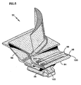
- FIG. 5 illustrates an isometric view of a turbine blade of the type used in the turbine of FIG. 2.
- FIG. 6a illustrates a front view of a ring segment interface comprising a single chamfered edge.
- FIG. 6b illustrates a front view of a ring segment interface comprising double chamfered edges.
- FIG. 6c illustrates a front view of a ring segment interface comprising a single sloped edge.
- FIG. 6d illustrates a front view of a ring segment interface comprising dual sloped edges.
- FIG. 6e illustrates a front view of a ring segment interface comprising tangentially sloped wings.
- FIG. 6f illustrates a front view of a ring segment interface comprising a single downstream dam.
- FIG. 6g illustrates a front view of a ring segment interface comprising dual dams.
- The major sections of a typical
gas turbine engine 10 of FIG. 1 include in series, from front to rear and disposed about a centrallongitudinal axis 11, a low-pressure compressor 12, a high-pressure compressor 14, acombustor 16, a high-pressure turbine 18 and a low-pressure turbine 20. A workingfluid 22 is directed rearward through thecompressors combustor 16, where fuel is injected and the mixture is burned.Hot combustion gases 24 exit thecombustor 16 and expand within anannular duct 26, driving theturbines turbines compressors concentric shafts high rotor spool 32 and alow rotor spool 34 respectively. Although adual spool engine 10 is depicted in the figure, threespool engines 10 are not uncommon. The combustion gases exit theengine 10 as apropulsive thrust 36, used to power an aircraft or a free turbine. A portion of the workingfluid 22 is bled from thecompressors combustor 16 and axially rearward to theturbines air 38. - In an exemplary low-
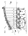
pressure turbine 20 of FIGS. 2-4, thecombustion gases 24 are directed rearward through anannular duct 40 approximately defined by a radiallyouter flow path 42 and a radially inner flow path 44. Disposed circumferentially within theannular duct 40 are alternating stages of rotating blades 50a-50e and stationary vanes 52a-52d. Theblades 50 extend radially outward from arotor disk 54 byroots 56 disposed radially inward ofplatforms 58. Eachblade 50 further comprises anairfoil 60, extending radially between theplatform 58 and anouter tip shroud 62. Theairfoil 60 has a forward facing leading edge and a rearward facing trailing edge. In some instances, theblades 50 are removable from thedisks 54 and in some instances non-removable. Thevanes 52 are cantilevered inward from a case 64 byhooks 66 extending radially outward from the outer tip shrouds 62. Eachvane 52 comprises anairfoil 60 that extends radially between aninner shroud 68 and anouter shroud 70. -
Outer seals 72 restrict leakage of the combustion gases 74 at theouter flow path 42. Theouter seals 72 are disposed at the interface of therotating blades 50 and the stationary case 64. The tip shrouds 62 contain outwardly extending runners 74 that radially cooperate with inwardly facing lands 76 affixed to the case 64 by supports 78. The radial cooperation of the runners 74 and thelands 76, along with the rotation of theblades 50, cause a damming effect and thus restricts leakage of thecombustion gases 24 from theouter flow path 42. Overlappingplatforms 58 and a constant supply of higherpressure cooling air 38 restrict leakage of thecombustion gases 24 at the inner flow path 44. - Cooling
air 38, bled from thecompressors cavities 80. The bore cavities 80 are bounded axially by adjacent disk bores 82 and radially outwardly by anannular coupling 84. Thecoupling 84 joinsadjacent disks 54 with bolts, rivets, welds, threads, splines, tapers, snap fits, or other means. Thecoupling 84 may also be integrally formed with each of the adjacent disks 82 (not shown). The coolingair 38 is pumped radially outward, against thecouplings 84, by the rotation of thedisks 54.Apertures 86 in thecouplings 84 direct the coolingair 38 intorim cavities 88. The apertures may be circular holes, slots, or other forms and are typically, evenly distributed cirumferentially about thecoupling 84. Theapertures 86 are sized to allow theappropriate cooling air 38 volume to enter therim cavity 88. - The cooling
air 38 inside therim cavity 88 is maintained at a higher pressure than thecombustion gases 24 in theannular duct 40 under all engine-operating conditions. The higherpressure cooling air 38 preventscombustion gas 24 ingestion into therim cavities 88 and provides cooling for theblade 50 to vane 52 interface. A portion of the coolingair 38 is directed axially rearward through a plurality ofslots 90 disposed between theblade roots 56 and thedisk 54. This portion of coolingair 38 reduces the temperature of theblade root 56 todisk 54 interface before being directed axially rearward to adownstream rim cavity 88. Another portion of the coolingair 38 is directed radially outward to cool theblade 50 to vane 52 interface region. - As specifically illustrated in FIGS. 3 and 4, seals 92 according to various embodiments of the current invention restrict the leakage of the cooling
air 38 at the interfaces of theblades 50 andvanes 52. Theblade platforms 58 form one or more circumferentiallysegmented rings 94 that radially cooperate with inwardly facing lands 96 affixed to thevanes 52. Also, one or moreintegral rings 94 may project radially outward from coupling 84 anywhere along its axial length as specifically illustrated in FIG. 4. The cooperation of the integral rings 94 and lands 96 form intermediate seals, whichpartition cavity 88 into two or moresmaller cavities 88. The radially outward projectingring 94 is not segmented and also radially cooperates with aland 96 affixed to avane 52. The proximate radial position of therings 94 and thelands 96, along with the rotation of theblades 50, cause a damming effect and thus restrict leakage of the coolingair 38 from therim cavity 88. - The
lands 96 may have a constant radial profile or may be stepped radially to further prevent ingestion of thecombustion gases 24 into therim cavity 88. Aland 96 may be affixed directly to thevane 52 by brazing, welding or other suitable means or may be affixed to asupport 97 projecting radially inwardly from thevane 52. Thesupport 97 may be integrated with thevane 52 or may be affixed by brazing, welding or other suitable means. Aland 96 is typically comprised of a honeycomb shaped, sheet metal structure, or any other structure and material known in the sealing art to restrict leakage. - The
rings 94 project axially from aplatform 58 of ablade 50 in a leading edge direction, a trailing edge direction, or both directions. Anintegral ring 94 may also project radially fromcoupling 84. With theblades 50 assembled into adisk 54,individual ring 94 segments axially and radially align, to form a substantiallycomplete ring 94 aboutcentral axis 11. Aring 94 may contain one or more radially extendingrunners 98, which are also known as knife-edges. The addition ofmultiple runners 98 provides agreater cooling air 38 leakage restriction, but the actual number may be dictated by space and/or weight limitations. The width of arunner 98 should be as thin as possible, adjacent to aland 96, to reduce the velocity of any coolingair 38 flowing therebetween. Since intermittent contact between arunner 98 and aland 96 may occur, a coating, hardface or other wear-resistant treatment is typically applied to therunners 98. Arunner 98 may also be canted at an angle (•) from between about 22.5 degrees to about 68 degrees, preferably 55 degrees, relative to the longitudinal axis of the segmentedring 94. By canting therunner 98 in the direction opposing the coolingair 38 flow, a damming effect is created, providing for an increased leakage restriction. Canting arunner 98 also reduces the length of the thicker, segmentedring 94, reducing weight even further. Therings 94 andrunners 98 are formed by casting, conventional machining, electrodischarge machining, chemical milling, or any other suitable manufacturing methods. - As further illustrated by the
blade 50 embodiment of FIG. 5,adjacent ring 94 segments may contain mechanical sealing elements to reduce leakage of coolingair 38 therebetween. With theblades 50 installed, atongue 100 and agroove 102 cooperate betweenadjacent ring 94 segments to reduce leakage of the coolingair 38. It is noted that thetongue 100 may be inclined radially outward to ensure it completely contacts thegroove 102 under centrifugal loading. Since an increased radial thickness of thering 94 segment is only required to accommodate thetongue 100 andgroove 102, one ormore pockets 104 are typically located between thetongue 100 and groove 102 to reduce the rotational mass of theblade 50. Thepockets 104 are formed by casting, conventional machining, electrodischarge machining, chemical milling or any other suitable manufacturing methods. - As illustrated in the
ring 94 segment embodiments of FIGS. 6a-6g,adjacent ring 94 segments may contain aerodynamic sealing means to reduce leakage of coolingair 38 therebetween. By directing a volume of coolingair 38 andcombustion gases 24 radially inward through the mechanism of reverse inward pumping, the radially outward leakage of coolingair 38 from therim cavity 88 is opposed, and therefore reduced. In each of the figures, the reference rotation of theblades 50 is in the clockwise direction. If the rotation of theblades 50 is in the counterclockwise direction, the inventive aerodynamic sealing elements are mirrored about a plane extending through thelongitudinal axis 11 of theengine 10. Also, theupstream ring 194 segment is illustrated to the right and thedownstream ring 294 segment is illustrated to the left in each of the figures. - FIG. 6a illustrates a
chamfered edge 106, reverse pumping element. Thechamfered edge 106 is located at the intersection of a tangentially facingsurface 108 and a radiallyouter surface 110 of theupstream ring 194 segment. A volume of coolingair 38 andcombustion gases 24 encounters the chamferededge 106 and is pumped radially inward, betweenadjacent ring blades 50. The inward pumping opposes the radially outward leakage of coolingair 38. - FIG. 6b illustrates a double
chamfered edge 106, reverse pumping element. Achamfered edge 106 is located at the intersection of a tangentially facingsurface 108 and a radiallyouter surface 110 of theupstream ring 194 segment. Also, achamfered edge 106 is located at the intersection of a tangentially facingsurface 108 and a radiallyinner surface 112 of thedownstream ring 294 segment. A volume of coolingair 38 andcombustion gases 24 encounters the chamferededges 106 and is pumped radially inward, betweenadjacent ring blades 50. The inward pumping opposes the radially outward leakage of coolingair 38. - FIG. 6c illustrates a single sloped
edge 114, reverse pumping element. Asloped edge 114 is located between a radiallyouter surface 110 and a radiallyinner surface 112 of theupstream ring 194 segment. A volume of coolingair 38 andcombustion gases 24 encounters thesloped edge 114 and is pumped radially inward, betweenadjacent ring blades 50. The inward pumping opposes the radially outward leakage of coolingair 38. - FIG. 6d illustrates a dual sloped
edge 114, reverse pumping element. Asloped edge 114 is located between a radiallyouter surface 110 and a radiallyinner surface 112 of theupstream ring 194 segment. Also, asloped edge 114 is located between a radiallyouter surface 110 and a radiallyinner surface 112 of thedownstream ring 194 segment. A volume of coolingair 38 andcombustion gases 24 encounters the slopededges 114 and is pumped radially inward, betweenadjacent ring blades 50. The inward pumping opposes the radially outward leakage of coolingair 38. - FIG. 6e illustrates a dual tangentially sloped
wing 116, reverse pumping element. A radially innersloped wing 116 is located adjacent the tangentially facingsurface 108 of theupstream ring 194 segment. Also, a radially outersloped wing 116 is located adjacent the tangentially facingsurface 108 of thedownstream ring 294 segment. A volume of coolingair 38 andcombustion gases 24 encounters thewings 116 and is pumped radially inward, betweenadjacent ring blades 50. The inward pumping opposes the radially outward leakage of coolingair 38. - FIG. 6f illustrates a single
downstream dam 118, reverse pumping element. The tangentially facingsurface 108 of thedownstream ring 294 segment is radially thickened and protrudes radially outward, beyond the tangentially facingsurface 108 of theupstream ring 194 segment to form thedam 118. A volume of coolingair 38 andcombustion gases 24 encounters thedam 118 and is pumped radially inward, betweenadjacent ring blades 50. The inward pumping opposes the radially outward leakage of coolingair 38. - FIG. 6g illustrates a
dual dam 118, reverse pumping feature. The tangentially facingsurface 108 of thedownstream ring 294 segment is radially thickened and protrudes radially outward, beyond the tangentially facingsurface 108 of theupstream ring 194 segment. Also, the tangentially facingsurface 108 of theupstream ring 194 segment is radially thickened and protrudes radially inward, beyond the tangentially facingsurface 108 of thedownstream ring 294 segment. A volume of coolingair 38 andcombustion gases 24 encounters the dam and is pumped radially inward, betweenadjacent ring blades 50. The inward pumping opposes the radially outward leakage of coolingair 38. - Although a low-
pressure turbine 20 is illustrated throughout the figures for succinctness, it is understood that high-pressure and mid-pressure turbines are similarly constructed and would therefore benefit from theexemplary seals 92 andrim cavity 88 cooling arrangements. - While the present invention has been described in the context of specific embodiments thereof, other alternatives, modifications and variations will become apparent to those skilled in the art having read the foregoing description. Accordingly, it is intended to embrace those alternatives, modifications and variations as fall within the broad scope of the appended claims.
Claims (32)
- An interstage seal comprising:a first rotor stage containing a plurality of outwardly extending blades (50);a second bladed rotor stage containing a plurality of outwardly extending blades (50), said second stage spaced axially from said first stage;a vane stage interposed between said rotor stages, said vane stage containing at least one radially inwardly directed land (96); andwherein each of said bladed rotor stages contains at least one ring (94) projecting from said blades (50), said rings (94) radially cooperating with said at least one land (96) to form the seal.
- The seal of claim 1 wherein at least one ring (94) projects from a platform (58) of said first rotor stage of blades (50).
- The seal of claim 2 wherein at least one ring (94) projects from a platform (58) of said second rotor stage of blades (50).
- The seal of claim 1, 2 or 3 wherein said vane stage contains two lands (96) and wherein a first of said lands (96) is located radially inward of a second of said lands (96).
- A cooled rotor to stator interface seal for a gas turbine engine comprising:a first rotor stage containing a first disk (54) and a plurality of first blades (50) extending radially outward from said first disk (54);a second rotor stage containing a second disk (54) and a plurality of second blades (50) extending radially outward from said second disk (54), said first and second stages being spaced apart to form a chamber (88) therebetween, said disks (54) being joined by an axially spanning, annular coupling (84) disposed radially inboard of said blades (50);a vane stage interposed between said first and second rotor stages, said vane stage containing at least one radially inwardly facing land (96);a ring (94) projecting axially from each of said first and second blades (50) and radially cooperating with the at least one land (96) to form the seal; andat least one aperture (86) through said coupling (84) for radially introducing a cooling fluid to said chamber (88) for use in cooling the seal.
- The seal of claim 5 further comprising a plurality of apertures in said first disk (54) for delivering a pressurized fluid into said chamber (88).
- The seal of claim 6 further comprising a plurality of apertures in said second disk (54) for removing a portion of the pressurized fluid from said chamber (88).
- The seal of claim 5, 6 or 7 wherein said coupling (54) further comprises a ring (94) protruding radially outward, said ring (94) radially cooperating with the at least one land (96) to form a portion of the seal.
- The seal of claim 8 wherein said at least one aperture is disposed axially forward of said vane stage.
- The seal of any preceding claim wherein each of the rings (94) or the at least one ring (94) contains a runner (98) disposed radially between said ring (94) and said land (96).
- The seal of claim 10 wherein each ring (94) contains exactly two runners (98).
- The seal of claim 10 or 11 wherein each runner (98) is canted at an angle towards the vane stage.
- The seal of claim 12 wherein the or each runner (98) is canted at an angle of between 22.5 degrees and 68 degrees towards the vane stage, more particularly in relation to said ring (94).
- The seal of claim 13 wherein the or each runner (98) is canted at an angle of 55 degrees towards the vane stage, more particularly in relation to said ring (94).
- The seal of any preceding claim wherein said rings (94) are circumferentially segmented.
- The seal of claim 15 wherein each blade (50) contains one segment of the ring (94).
- The seal of claim 15 or 16 wherein each segment of the ring (94) contains a tongue (100) and a groove (102) and wherein the tongue (100) and the groove (102) of adjacent ring segments cooperate when installed.
- The seal of claim 17 wherein each tongue (100) is inclined in the outward radial direction.
- The seal of claim 18 wherein said ring segments contain at least one pocket (104) disposed circumferentially between said tongue (100) and said groove (102).
- The seal of any of claims 15 to 19 wherein said ring segments contain an aerodynamic sealing means.
- The seal of any preceding claim wherein a land (96) is located radially inward of another land (96).
- A turbine blade (50) comprising:a radially innermost attachment (56) for engaging a rotor;a platform (58) disposed radially outward from said attachment (56);an airfoil (60) extending radially outward from said platform (58); andat least one ring (94) segment protruding axially from said platform (58).
- The blade of claim 22 wherein said airfoil (60) contains a leading edge facing axially forward and a trailing edge facing axially rearward; and
wherein a first ring (94) segment protrudes from the platform (58) in the leading edge direction and a second ring (94) segment protrudes from the platform (58) in the trailing edge direction. - The blade of claim 23 wherein each ring (94) segment contains at least one runner (98) extending radially outward therefrom.
- The blade of claim 24 wherein each ring (94) segment contains exactly two runners (98).
- The blade of claim 24, 25 or 26 wherein each runner (98) is canted at an angle away from said airfoil (60).
- The blade of claim 26 wherein each runner (98) is canted at an angle of between 157.5 degrees and 112 degrees in relation to said ring (94) segment.
- The blade of claim 27 wherein each runner (98) is canted at an angle of 125 degrees in relation to said ring (94) segment.
- The blade of any of claims 22 to 28 wherein said ring (94) segments contain a tongue (100) and a groove (102).
- The blade of claim 29 wherein said tongue (100) is inclined in the outward radial direction.
- The blade of claim 29 or 30 wherein said ring (94) segments contain a pocket (104) disposed circumferentially between said tongue (100) and said groove (102).
- The blade of claim 31 wherein said ring (94) segments contain an aerodynamic sealing means.
Applications Claiming Priority (1)
| Application Number | Priority Date | Filing Date | Title |
|---|---|---|---|
| US11/260,357 US7334983B2 (en) | 2005-10-27 | 2005-10-27 | Integrated bladed fluid seal |
Publications (3)
| Publication Number | Publication Date |
|---|---|
| EP1780380A2 true EP1780380A2 (en) | 2007-05-02 |
| EP1780380A3 EP1780380A3 (en) | 2011-07-20 |
| EP1780380B1 EP1780380B1 (en) | 2017-11-29 |
Family
ID=37776593
Family Applications (1)
| Application Number | Title | Priority Date | Filing Date |
|---|---|---|---|
| EP06255507.3A Active EP1780380B1 (en) | 2005-10-27 | 2006-10-26 | Gas turbine blade to vane interface seal |
Country Status (4)
| Country | Link |
|---|---|
| US (1) | US7334983B2 (en) |
| EP (1) | EP1780380B1 (en) |
| JP (1) | JP2007120501A (en) |
| CA (1) | CA2564073A1 (en) |
Cited By (12)
| Publication number | Priority date | Publication date | Assignee | Title |
|---|---|---|---|---|
| DE102008014743A1 (en) * | 2008-03-18 | 2009-09-24 | Rolls-Royce Deutschland Ltd & Co Kg | Compressor stator with partial cover tape |
| EP1967700A3 (en) * | 2007-03-05 | 2010-05-05 | United Technologies Corporation | Labyrinth seal having canted pockets and knife edges, and gas turbine engine with such a seal |
| EP1930551A3 (en) * | 2006-11-29 | 2010-05-12 | United Technologies Corporation | Seal with concave recess and corresponding gas turbine engine |
| EP1895108A3 (en) * | 2006-08-22 | 2012-07-18 | General Electric Company | Angel wing abradable seal and sealing method |
| EP2105581A3 (en) * | 2008-03-24 | 2012-12-19 | United Technologies Corporation | Vane with integral inner air seal |
| EP2613008A1 (en) * | 2012-01-04 | 2013-07-10 | General Electric Company | Modification of turbine engine seal abradability |
| EP2938867A4 (en) * | 2012-12-29 | 2016-04-20 | United Technologies Corp | Flow diverter to redirect secondary flow |
| CN106062314A (en) * | 2014-02-25 | 2016-10-26 | 西门子能源公司 | Thermal shields for gas turbine rotor |
| FR3040461A1 (en) * | 2015-09-02 | 2017-03-03 | Snecma | LABYRINTH SEALING ELEMENT FOR TURBINE |
| CN109477389A (en) * | 2016-05-31 | 2019-03-15 | 通用电气公司 | System and method for the sealing element in circuit to be discharged in the machine in turbine |
| EP3862533A1 (en) * | 2020-02-07 | 2021-08-11 | Rolls-Royce plc | Rotor assembly |
| FR3107312A1 (en) * | 2020-02-13 | 2021-08-20 | Safran Aircraft Engines | Rotary assembly for turbomachine |
Families Citing this family (34)
| Publication number | Priority date | Publication date | Assignee | Title |
|---|---|---|---|---|
| JP2006097585A (en) * | 2004-09-29 | 2006-04-13 | Mitsubishi Heavy Ind Ltd | Mounting structure for air separator and gas turbine provided with the same |
| US8128371B2 (en) * | 2007-02-15 | 2012-03-06 | General Electric Company | Method and apparatus to facilitate increasing turbine rotor efficiency |
| DE602007007333D1 (en) * | 2007-09-24 | 2010-08-05 | Alstom Technology Ltd | Gasket in gas turbine |
| US7918265B2 (en) | 2008-02-14 | 2011-04-05 | United Technologies Corporation | Method and apparatus for as-cast seal on turbine blades |
| FR2928961B1 (en) * | 2008-03-19 | 2015-11-13 | Snecma | SECTORIZED DISPENSER FOR A TURBOMACHINE. |
| JP2010077869A (en) * | 2008-09-25 | 2010-04-08 | Mitsubishi Heavy Ind Ltd | Rim seal structure of gas turbine |
| GB2467350A (en) * | 2009-02-02 | 2010-08-04 | Rolls Royce Plc | Cooling and sealing in gas turbine engine turbine stage |
| DE102009007664A1 (en) * | 2009-02-05 | 2010-08-12 | Mtu Aero Engines Gmbh | Sealing device on the blade shank of a rotor stage of an axial flow machine |
| US8282346B2 (en) * | 2009-04-06 | 2012-10-09 | General Electric Company | Methods, systems and/or apparatus relating to seals for turbine engines |
| IT1403415B1 (en) * | 2010-12-21 | 2013-10-17 | Avio Spa | GAS TURBINE FOR AERONAUTICAL MOTORS |
| US8888459B2 (en) * | 2011-08-23 | 2014-11-18 | General Electric Company | Coupled blade platforms and methods of sealing |
| US9115591B2 (en) | 2011-08-30 | 2015-08-25 | United Technologies Corporation | Universal seal |
| US8926269B2 (en) | 2011-09-06 | 2015-01-06 | General Electric Company | Stepped, conical honeycomb seal carrier |
| US9416673B2 (en) * | 2012-01-17 | 2016-08-16 | United Technologies Corporation | Hybrid inner air seal for gas turbine engines |
| US9017013B2 (en) | 2012-02-07 | 2015-04-28 | Siemens Aktiengesellschaft | Gas turbine engine with improved cooling between turbine rotor disk elements |
| US9097128B2 (en) * | 2012-02-28 | 2015-08-04 | General Electric Company | Seals for rotary devices and methods of producing the same |
| US9175567B2 (en) | 2012-02-29 | 2015-11-03 | United Technologies Corporation | Low loss airfoil platform trailing edge |
| US9181815B2 (en) * | 2012-05-02 | 2015-11-10 | United Technologies Corporation | Shaped rim cavity wing surface |
| US10053998B2 (en) * | 2012-12-29 | 2018-08-21 | United Technologies Corporation | Multi-purpose gas turbine seal support and assembly |
| US10344603B2 (en) | 2013-07-30 | 2019-07-09 | United Technologies Corporation | Gas turbine engine turbine vane ring arrangement |
| EP3068997B1 (en) * | 2013-11-11 | 2021-12-29 | Raytheon Technologies Corporation | Segmented seal for gas turbine engine |
| US10370987B2 (en) * | 2014-04-03 | 2019-08-06 | Mitsubishi Hitachi Power Systems, Ltd. | Blade or vane row and gas turbine |
| US20160230579A1 (en) * | 2015-02-06 | 2016-08-11 | United Technologies Corporation | Rotor disk sealing and blade attachments system |
| US10030582B2 (en) | 2015-02-09 | 2018-07-24 | United Technologies Corporation | Orientation feature for swirler tube |
| US10337345B2 (en) | 2015-02-20 | 2019-07-02 | General Electric Company | Bucket mounted multi-stage turbine interstage seal and method of assembly |
| US10060280B2 (en) * | 2015-10-15 | 2018-08-28 | United Technologies Corporation | Turbine cavity sealing assembly |
| US10240461B2 (en) | 2016-01-08 | 2019-03-26 | General Electric Company | Stator rim for a turbine engine |
| US10428661B2 (en) * | 2016-10-26 | 2019-10-01 | Roll-Royce North American Technologies Inc. | Turbine wheel assembly with ceramic matrix composite components |
| DE102017108581A1 (en) * | 2017-04-21 | 2018-10-25 | Rolls-Royce Deutschland Ltd & Co Kg | Turbomachine with an adaptive sealing device |
| US10480333B2 (en) * | 2017-05-30 | 2019-11-19 | United Technologies Corporation | Turbine blade including balanced mateface condition |
| US10329938B2 (en) * | 2017-05-31 | 2019-06-25 | General Electric Company | Aspirating face seal starter tooth abradable pocket |
| US10669877B2 (en) * | 2017-12-21 | 2020-06-02 | United Technologies Corporation | Air seal attachment |
| FR3085412B1 (en) * | 2018-08-31 | 2020-12-04 | Safran Aircraft Engines | TURBOMACHINE DISTRIBUTOR AREA INCLUDING AN ANTI-ROTATION NOTCH WITH WEAR INSERT |
| GB202005789D0 (en) | 2020-03-03 | 2020-06-03 | Itp Next Generation Turbines S L U | Blade assembly for gas turbine engine |
Citations (8)
| Publication number | Priority date | Publication date | Assignee | Title |
|---|---|---|---|---|
| US4103899A (en) * | 1975-10-01 | 1978-08-01 | United Technologies Corporation | Rotary seal with pressurized air directed at fluid approaching the seal |
| EP0169799A1 (en) * | 1984-07-23 | 1986-01-29 | United Technologies Corporation | Breech lock anti-rotation key |
| US4820116A (en) * | 1987-09-18 | 1989-04-11 | United Technologies Corporation | Turbine cooling for gas turbine engine |
| WO2000004278A1 (en) * | 1998-07-16 | 2000-01-27 | Siemens Westinghouse Power Corporation | A turbine interstage sealing arrangement |
| EP1094200A1 (en) * | 1998-07-17 | 2001-04-25 | Mitsubishi Heavy Industries, Ltd. | Gas turbine cooled moving blade |
| EP1188901A2 (en) * | 2000-09-15 | 2002-03-20 | General Electric Company | Bypass holes for rotor cooling |
| JP2004011580A (en) * | 2002-06-10 | 2004-01-15 | Toshiba Corp | Gas turbine rotor |
| FR2895021A1 (en) * | 2005-12-16 | 2007-06-22 | Snecma Sa | Turbomachine e.g. low pressure turbine, for aircraft`s jet engine, has rotor composed of disks that are reunited by annular connecting part, and sealing unit arranged between blades of each disks and crown of diffuser blade |
Family Cites Families (6)
| Publication number | Priority date | Publication date | Assignee | Title |
|---|---|---|---|---|
| GB1318654A (en) * | 1970-12-05 | 1973-05-31 | Secr Defence | Bladed rotors |
| JPH10252412A (en) * | 1997-03-12 | 1998-09-22 | Mitsubishi Heavy Ind Ltd | Gas turbine sealing device |
| DE69934570T2 (en) * | 1999-01-06 | 2007-10-04 | General Electric Co. | Cover plate for a turbine rotor |
| WO2003052240A2 (en) * | 2001-12-14 | 2003-06-26 | Alstom Technology Ltd | Gas turbine system |
| DE10318852A1 (en) * | 2003-04-25 | 2004-11-11 | Rolls-Royce Deutschland Ltd & Co Kg | Main gas duct inner seal of a high pressure turbine |
| US6899520B2 (en) | 2003-09-02 | 2005-05-31 | General Electric Company | Methods and apparatus to reduce seal rubbing within gas turbine engines |
-
2005
- 2005-10-27 US US11/260,357 patent/US7334983B2/en active Active
-
2006
- 2006-10-13 CA CA002564073A patent/CA2564073A1/en not_active Abandoned
- 2006-10-26 EP EP06255507.3A patent/EP1780380B1/en active Active
- 2006-10-26 JP JP2006290590A patent/JP2007120501A/en active Pending
Patent Citations (8)
| Publication number | Priority date | Publication date | Assignee | Title |
|---|---|---|---|---|
| US4103899A (en) * | 1975-10-01 | 1978-08-01 | United Technologies Corporation | Rotary seal with pressurized air directed at fluid approaching the seal |
| EP0169799A1 (en) * | 1984-07-23 | 1986-01-29 | United Technologies Corporation | Breech lock anti-rotation key |
| US4820116A (en) * | 1987-09-18 | 1989-04-11 | United Technologies Corporation | Turbine cooling for gas turbine engine |
| WO2000004278A1 (en) * | 1998-07-16 | 2000-01-27 | Siemens Westinghouse Power Corporation | A turbine interstage sealing arrangement |
| EP1094200A1 (en) * | 1998-07-17 | 2001-04-25 | Mitsubishi Heavy Industries, Ltd. | Gas turbine cooled moving blade |
| EP1188901A2 (en) * | 2000-09-15 | 2002-03-20 | General Electric Company | Bypass holes for rotor cooling |
| JP2004011580A (en) * | 2002-06-10 | 2004-01-15 | Toshiba Corp | Gas turbine rotor |
| FR2895021A1 (en) * | 2005-12-16 | 2007-06-22 | Snecma Sa | Turbomachine e.g. low pressure turbine, for aircraft`s jet engine, has rotor composed of disks that are reunited by annular connecting part, and sealing unit arranged between blades of each disks and crown of diffuser blade |
Cited By (22)
| Publication number | Priority date | Publication date | Assignee | Title |
|---|---|---|---|---|
| EP1895108A3 (en) * | 2006-08-22 | 2012-07-18 | General Electric Company | Angel wing abradable seal and sealing method |
| EP1930551A3 (en) * | 2006-11-29 | 2010-05-12 | United Technologies Corporation | Seal with concave recess and corresponding gas turbine engine |
| EP1967700A3 (en) * | 2007-03-05 | 2010-05-05 | United Technologies Corporation | Labyrinth seal having canted pockets and knife edges, and gas turbine engine with such a seal |
| US8167547B2 (en) | 2007-03-05 | 2012-05-01 | United Technologies Corporation | Gas turbine engine with canted pocket and canted knife edge seal |
| US8235654B2 (en) | 2008-03-18 | 2012-08-07 | Rolls-Royce Deutschland Ltd & Co Kg | Compressor stator with partial shroud |
| DE102008014743A1 (en) * | 2008-03-18 | 2009-09-24 | Rolls-Royce Deutschland Ltd & Co Kg | Compressor stator with partial cover tape |
| EP2105581A3 (en) * | 2008-03-24 | 2012-12-19 | United Technologies Corporation | Vane with integral inner air seal |
| RU2615088C2 (en) * | 2012-01-04 | 2017-04-03 | Дженерал Электрик Компани | Seal, seal of turbine engine and method of producing the seal |
| EP2613008A1 (en) * | 2012-01-04 | 2013-07-10 | General Electric Company | Modification of turbine engine seal abradability |
| US9175575B2 (en) | 2012-01-04 | 2015-11-03 | General Electric Company | Modification of turbine engine seal abradability |
| US10094389B2 (en) | 2012-12-29 | 2018-10-09 | United Technologies Corporation | Flow diverter to redirect secondary flow |
| EP2938867A4 (en) * | 2012-12-29 | 2016-04-20 | United Technologies Corp | Flow diverter to redirect secondary flow |
| CN106062314A (en) * | 2014-02-25 | 2016-10-26 | 西门子能源公司 | Thermal shields for gas turbine rotor |
| US9771802B2 (en) | 2014-02-25 | 2017-09-26 | Siemens Energy, Inc. | Thermal shields for gas turbine rotor |
| FR3040461A1 (en) * | 2015-09-02 | 2017-03-03 | Snecma | LABYRINTH SEALING ELEMENT FOR TURBINE |
| WO2017037394A1 (en) * | 2015-09-02 | 2017-03-09 | Safran Aircraft Engines | Turbine of gas turbine engine, including a labyrinth sealing joint element |
| US10605106B2 (en) | 2015-09-02 | 2020-03-31 | Safran Aircraft Engines | Turbine of gas turbine engine, comprising a labyrinth seal element |
| RU2722122C2 (en) * | 2015-09-02 | 2020-05-26 | Сафран Эркрафт Энджинз | Turbine of gas turbine engine containing labyrinth seal element |
| CN109477389A (en) * | 2016-05-31 | 2019-03-15 | 通用电气公司 | System and method for the sealing element in circuit to be discharged in the machine in turbine |
| EP3862533A1 (en) * | 2020-02-07 | 2021-08-11 | Rolls-Royce plc | Rotor assembly |
| US11834958B2 (en) | 2020-02-07 | 2023-12-05 | Rolls-Royce Plc | Rotor assembly |
| FR3107312A1 (en) * | 2020-02-13 | 2021-08-20 | Safran Aircraft Engines | Rotary assembly for turbomachine |
Also Published As
| Publication number | Publication date |
|---|---|
| EP1780380A3 (en) | 2011-07-20 |
| EP1780380B1 (en) | 2017-11-29 |
| JP2007120501A (en) | 2007-05-17 |
| CA2564073A1 (en) | 2007-04-27 |
| US20070098545A1 (en) | 2007-05-03 |
| US7334983B2 (en) | 2008-02-26 |
Similar Documents
| Publication | Publication Date | Title |
|---|---|---|
| EP1780380B1 (en) | Gas turbine blade to vane interface seal | |
| EP1211386B1 (en) | Turbine interstage sealing ring and corresponding turbine | |
| EP0900920B1 (en) | One-piece blisk of a gas turbine engine | |
| US8419356B2 (en) | Turbine seal assembly | |
| EP1398474B1 (en) | Compressor bleed case | |
| EP1731717A2 (en) | Seal assembly for sealing space between stator and rotor in a gas turbine | |
| EP3121382B1 (en) | Gas turbine engines including channel-cooled hooks for retaining a part relative to an engine casing structure | |
| US7048496B2 (en) | Turbine cooling, purge, and sealing system | |
| EP1731718A2 (en) | Seal assembly for sealing the gap between stator blades and rotor rim | |
| CN108798804B (en) | Spline for turbine engine | |
| EP2924237B1 (en) | Gas turbine rotor | |
| CN110325711B (en) | Spline of turbine engine | |
| US8312729B2 (en) | Flow discouraging systems and gas turbine engines | |
| US10053998B2 (en) | Multi-purpose gas turbine seal support and assembly | |
| EP2551458A2 (en) | Blade Cooling and Sealing System | |
| US20180142564A1 (en) | Combined turbine nozzle and shroud deflection limiter | |
| US20190136700A1 (en) | Ceramic matrix composite tip shroud assembly for gas turbines | |
| EP2143881B1 (en) | Labyrinth seal for turbine blade dovetail root and corresponding sealing method | |
| US6129513A (en) | Fluid seal | |
| US20060275108A1 (en) | Hammerhead fluid seal | |
| US11098605B2 (en) | Rim seal arrangement | |
| US11732604B1 (en) | Ceramic matrix composite blade track segment with integrated cooling passages | |
| EP3839218B1 (en) | Improved rotor blade sealing structures | |
| WO2019177599A1 (en) | Canted honeycomb abradable structure for a gas turbine |
Legal Events
| Date | Code | Title | Description |
|---|---|---|---|
| PUAI | Public reference made under article 153(3) epc to a published international application that has entered the european phase |
Free format text: ORIGINAL CODE: 0009012 |
|
| AK | Designated contracting states |
Kind code of ref document: A2 Designated state(s): AT BE BG CH CY CZ DE DK EE ES FI FR GB GR HU IE IS IT LI LT LU LV MC NL PL PT RO SE SI SK TR |
|
| AX | Request for extension of the european patent |
Extension state: AL BA HR MK YU |
|
| PUAL | Search report despatched |
Free format text: ORIGINAL CODE: 0009013 |
|
| AK | Designated contracting states |
Kind code of ref document: A3 Designated state(s): AT BE BG CH CY CZ DE DK EE ES FI FR GB GR HU IE IS IT LI LT LU LV MC NL PL PT RO SE SI SK TR |
|
| AX | Request for extension of the european patent |
Extension state: AL BA HR MK RS |
|
| 17P | Request for examination filed |
Effective date: 20120120 |
|
| AKX | Designation fees paid |
Designated state(s): DE GB |
|
| 17Q | First examination report despatched |
Effective date: 20150909 |
|
| RAP1 | Party data changed (applicant data changed or rights of an application transferred) |
Owner name: UNITED TECHNOLOGIES CORPORATION |
|
| REG | Reference to a national code |
Ref country code: DE Ref legal event code: R079 Ref document number: 602006054219 Country of ref document: DE Free format text: PREVIOUS MAIN CLASS: F01D0011000000 Ipc: F01D0005080000 |
|
| GRAP | Despatch of communication of intention to grant a patent |
Free format text: ORIGINAL CODE: EPIDOSNIGR1 |
|
| RIC1 | Information provided on ipc code assigned before grant |
Ipc: F01D 11/02 20060101ALI20161110BHEP Ipc: F02C 7/28 20060101ALI20161110BHEP Ipc: F01D 5/08 20060101AFI20161110BHEP Ipc: F01D 11/00 20060101ALI20161110BHEP |
|
| INTG | Intention to grant announced |
Effective date: 20161201 |
|
| GRAJ | Information related to disapproval of communication of intention to grant by the applicant or resumption of examination proceedings by the epo deleted |
Free format text: ORIGINAL CODE: EPIDOSDIGR1 |
|
| INTC | Intention to grant announced (deleted) | ||
| GRAR | Information related to intention to grant a patent recorded |
Free format text: ORIGINAL CODE: EPIDOSNIGR71 |
|
| GRAS | Grant fee paid |
Free format text: ORIGINAL CODE: EPIDOSNIGR3 |
|
| GRAA | (expected) grant |
Free format text: ORIGINAL CODE: 0009210 |
|
| INTG | Intention to grant announced |
Effective date: 20171012 |
|
| AK | Designated contracting states |
Kind code of ref document: B1 Designated state(s): DE GB |
|
| REG | Reference to a national code |
Ref country code: GB Ref legal event code: FG4D |
|
| REG | Reference to a national code |
Ref country code: DE Ref legal event code: R096 Ref document number: 602006054219 Country of ref document: DE |
|
| REG | Reference to a national code |
Ref country code: DE Ref legal event code: R097 Ref document number: 602006054219 Country of ref document: DE |
|
| PLBE | No opposition filed within time limit |
Free format text: ORIGINAL CODE: 0009261 |
|
| STAA | Information on the status of an ep patent application or granted ep patent |
Free format text: STATUS: NO OPPOSITION FILED WITHIN TIME LIMIT |
|
| 26N | No opposition filed |
Effective date: 20180830 |
|
| PGFP | Annual fee paid to national office [announced via postgrant information from national office to epo] |
Ref country code: DE Payment date: 20190918 Year of fee payment: 14 |
|
| REG | Reference to a national code |
Ref country code: DE Ref legal event code: R119 Ref document number: 602006054219 Country of ref document: DE |
|
| PG25 | Lapsed in a contracting state [announced via postgrant information from national office to epo] |
Ref country code: DE Free format text: LAPSE BECAUSE OF NON-PAYMENT OF DUE FEES Effective date: 20210501 |
|
| PGFP | Annual fee paid to national office [announced via postgrant information from national office to epo] |
Ref country code: GB Payment date: 20230920 Year of fee payment: 18 |