JP6441611B2 - Gas turbine exhaust member and exhaust chamber maintenance method - Google Patents
Gas turbine exhaust member and exhaust chamber maintenance method Download PDFInfo
- Publication number
- JP6441611B2 JP6441611B2 JP2014170775A JP2014170775A JP6441611B2 JP 6441611 B2 JP6441611 B2 JP 6441611B2 JP 2014170775 A JP2014170775 A JP 2014170775A JP 2014170775 A JP2014170775 A JP 2014170775A JP 6441611 B2 JP6441611 B2 JP 6441611B2
- Authority
- JP
- Japan
- Prior art keywords
- seal housing
- exhaust
- end portion
- casing
- axial direction
- Prior art date
- Legal status (The legal status is an assumption and is not a legal conclusion. Google has not performed a legal analysis and makes no representation as to the accuracy of the status listed.)
- Active
Links
Images


Classifications
-
- F—MECHANICAL ENGINEERING; LIGHTING; HEATING; WEAPONS; BLASTING
- F01—MACHINES OR ENGINES IN GENERAL; ENGINE PLANTS IN GENERAL; STEAM ENGINES
- F01D—NON-POSITIVE DISPLACEMENT MACHINES OR ENGINES, e.g. STEAM TURBINES
- F01D25/00—Component parts, details, or accessories, not provided for in, or of interest apart from, other groups
- F01D25/24—Casings; Casing parts, e.g. diaphragms, casing fastenings
- F01D25/243—Flange connections; Bolting arrangements
-
- F—MECHANICAL ENGINEERING; LIGHTING; HEATING; WEAPONS; BLASTING
- F01—MACHINES OR ENGINES IN GENERAL; ENGINE PLANTS IN GENERAL; STEAM ENGINES
- F01D—NON-POSITIVE DISPLACEMENT MACHINES OR ENGINES, e.g. STEAM TURBINES
- F01D25/00—Component parts, details, or accessories, not provided for in, or of interest apart from, other groups
- F01D25/30—Exhaust heads, chambers, or the like
-
- F—MECHANICAL ENGINEERING; LIGHTING; HEATING; WEAPONS; BLASTING
- F01—MACHINES OR ENGINES IN GENERAL; ENGINE PLANTS IN GENERAL; STEAM ENGINES
- F01D—NON-POSITIVE DISPLACEMENT MACHINES OR ENGINES, e.g. STEAM TURBINES
- F01D25/00—Component parts, details, or accessories, not provided for in, or of interest apart from, other groups
- F01D25/08—Cooling; Heating; Heat-insulation
- F01D25/14—Casings modified therefor
-
- F—MECHANICAL ENGINEERING; LIGHTING; HEATING; WEAPONS; BLASTING
- F01—MACHINES OR ENGINES IN GENERAL; ENGINE PLANTS IN GENERAL; STEAM ENGINES
- F01D—NON-POSITIVE DISPLACEMENT MACHINES OR ENGINES, e.g. STEAM TURBINES
- F01D25/00—Component parts, details, or accessories, not provided for in, or of interest apart from, other groups
- F01D25/24—Casings; Casing parts, e.g. diaphragms, casing fastenings
- F01D25/246—Fastening of diaphragms or stator-rings
-
- F—MECHANICAL ENGINEERING; LIGHTING; HEATING; WEAPONS; BLASTING
- F02—COMBUSTION ENGINES; HOT-GAS OR COMBUSTION-PRODUCT ENGINE PLANTS
- F02C—GAS-TURBINE PLANTS; AIR INTAKES FOR JET-PROPULSION PLANTS; CONTROLLING FUEL SUPPLY IN AIR-BREATHING JET-PROPULSION PLANTS
- F02C7/00—Features, components parts, details or accessories, not provided for in, or of interest apart form groups F02C1/00 - F02C6/00; Air intakes for jet-propulsion plants
Landscapes
- Engineering & Computer Science (AREA)
- Mechanical Engineering (AREA)
- General Engineering & Computer Science (AREA)
- Chemical & Material Sciences (AREA)
- Combustion & Propulsion (AREA)
- Turbine Rotor Nozzle Sealing (AREA)
- Supercharger (AREA)
Description
本発明は、圧縮機と燃焼器とタービンとを有するガスタービンにおいて、排気を処理するガスタービンの排気部材及び排気室メンテナンス方法に関するものである。 The present invention relates to an exhaust member and an exhaust chamber maintenance method for a gas turbine that processes exhaust gas in a gas turbine having a compressor, a combustor, and a turbine.
例えば、一般的なガスタービンは、圧縮機と燃焼器とタービンにより構成されている。圧縮機は、空気取入口から取り込まれた空気を圧縮することで高温・高圧の圧縮空気にする。燃焼器は、この圧縮空気に対して燃料を供給して燃焼させることで高温・高圧の燃焼ガスを得る。タービンは、この燃焼ガスにより駆動し、同軸上に連結された発電機を駆動する。 For example, a general gas turbine includes a compressor, a combustor, and a turbine. The compressor compresses the air taken in from the air intake port into high-temperature and high-pressure compressed air. The combustor obtains high-temperature and high-pressure combustion gas by supplying fuel to the compressed air and burning it. The turbine is driven by this combustion gas, and drives a generator connected on the same axis.
このガスタービンにおいて、タービンの下流側に円筒形状をなす排気部材が設けられている。この排気部材は、例えば、排気車室と排気室と排気ダクトが長手方向に連結して構成されている。そして、この排気車室と排気室は、ロータなどの内部構造物の組付性やメンテナンス性などを考慮して上下に2分割され、上下の分割面のフランジ部が複数の締結ボルトにより締結されることで円筒形状をなしている。また、排気車室と排気室は、排気ガスの流動時に、熱伸び差が発生することを考慮し、軸方向に相対的に移動可能に連結されている。このようなガスタービンとしては、例えば、下記特許文献1に記載されたものがある。 In this gas turbine, an exhaust member having a cylindrical shape is provided on the downstream side of the turbine. The exhaust member is configured, for example, by connecting an exhaust casing, an exhaust chamber, and an exhaust duct in the longitudinal direction. The exhaust casing and the exhaust chamber are divided into two parts in the vertical direction in consideration of the ease of assembly and maintenance of internal structures such as the rotor, and the flange parts of the upper and lower divided surfaces are fastened by a plurality of fastening bolts. It has a cylindrical shape. The exhaust casing and the exhaust chamber are connected so as to be relatively movable in the axial direction in consideration of the occurrence of a difference in thermal expansion when the exhaust gas flows. An example of such a gas turbine is described in Patent Document 1 below.
上述したように従来のガスタービンにおいて、この排気車室と排気室は、ガスタービンの運転時に内部に排気ガスが流動することで加熱され、軸方向や径方向に熱伸びが発生する。このとき、排気車室と排気室は、それぞれ上下に2分割された分割面で締結ボルトにより締結されていることから、特に、締結ボルトによる締結部で塑性変形が発生し、ガスタービンの停止後も、塑性ひずみが残存する。そして、排気車室と排気室を構成する各上部ケーシング同士が嵌着してしまい、取外すことが困難となる。すると、ガスタービンのメンテナンス作業を行うことができないという課題がある。また、排気車室と排気室の各上部ケーシングを取外すことができたとしても、各ケーシングが塑性変形していることから、再度組付けることができない。 As described above, in the conventional gas turbine, the exhaust casing and the exhaust chamber are heated by the exhaust gas flowing inside during operation of the gas turbine, and thermal expansion occurs in the axial direction and the radial direction. At this time, the exhaust casing and the exhaust chamber are fastened by fastening bolts at the split surfaces that are divided into two parts in the vertical direction. However, plastic strain remains. And each upper casing which comprises an exhaust casing and an exhaust chamber will fit, and it will become difficult to remove. Then, there exists a subject that the maintenance operation of a gas turbine cannot be performed. Even if the upper casings of the exhaust casing and the exhaust chamber can be removed, they cannot be assembled again because the casings are plastically deformed.
本発明は、上述した課題を解決するものであり、ケーシングの取外しと取付けを容易としてメンテナンス性の向上を図るガスタービンの排気部材及び排気室メンテナンス方法を提供することを目的とする。 The present invention solves the above-described problems, and an object thereof is to provide an exhaust member and an exhaust chamber maintenance method for a gas turbine that facilitate the removal and attachment of a casing and improve the maintainability.
上記の目的を達成するための本発明のガスタービンの排気部材は、円筒形状をなして周方向に複数分割される第1ケーシングと、円筒形状をなして周方向に一体構成されて軸方向における前端部が前記第1ケーシングの軸方向における後端部に連結される第2ケーシングと、円筒形状をなして周方向に一体構成されて軸方向における前端部が前記第2ケーシングの軸方向における後端部に連結される第3ケーシングと、前記第2ケーシングの後端部と前記第3ケーシングの前端部とを軸方向に移動可能に支持する支持連結部と、を有することを特徴とするものである。 In order to achieve the above object, an exhaust member of a gas turbine according to the present invention includes a first casing that has a cylindrical shape and is divided into a plurality of portions in the circumferential direction, and a cylindrical shape that is integrally configured in the circumferential direction and is axially configured. A second casing connected to a rear end portion in the axial direction of the first casing and a cylindrical shape integrally formed in the circumferential direction, and a front end portion in the axial direction is a rear end in the axial direction of the second casing. A third casing coupled to the end; and a support coupling that supports the rear end of the second casing and the front end of the third casing so as to be movable in the axial direction. It is.
従って、周方向に分割される第1ケーシングに周方向に一体構成される第2ケーシングが連結され、この第2ケーシングに周方向に一体構成される第3ケーシングが支持連結部により連結される。支持連結部により、第3ケーシングは第2ケーシングに対して軸方向に相対的に移動可能に支持される。ガスタービンの運転時に、各ケーシングが内部に流動する燃焼ガスにより加熱され、軸方向及び径方向に異なる量の熱伸びが発生すると、異なる量の塑性変形が内部応力として残存するおそれがある。しかし、第2ケーシングと第3ケーシングは、周方向に一体構成されていることから、冷却後には元の形状に戻ることとなり、両者が嵌着することはなく、支持連結部による軸方向の円滑な移動が可能となる。そのため、第1ケーシングが上下に分割されていることにより第1ケーシングの上部側を容易に取外すことができると共に、第2ケーシングと第3ケーシングを容易に分離することができ、各ケーシングの取外しと取付けを容易としてメンテナンス性の向上を図ることができる。 Therefore, the 2nd casing comprised integrally with the circumferential direction is connected with the 1st casing divided | segmented into the circumferential direction, and the 3rd casing comprised integrally with the circumferential direction is connected with this 2nd casing by the support connection part. By the support connecting portion, the third casing is supported so as to be movable relative to the second casing in the axial direction. When the gas turbine is operated, each casing is heated by the combustion gas flowing inside, and if different amounts of thermal elongation occur in the axial direction and the radial direction, different amounts of plastic deformation may remain as internal stresses. However, since the second casing and the third casing are integrally configured in the circumferential direction, they return to the original shape after cooling, and the two do not fit together, and the smooth smoothness in the axial direction by the support connecting portion. Movement is possible. Therefore, since the first casing is divided vertically, the upper side of the first casing can be easily removed, and the second casing and the third casing can be easily separated, and each casing can be removed. Installation can be facilitated and maintenance can be improved.
本発明のガスタービンの排気部材では、前記第2ケーシングの前端部は、前記第1ケーシング内に配置される回転軸の後端部より後方に配置されることを特徴とする。 In the exhaust member of the gas turbine according to the present invention, the front end portion of the second casing is disposed behind the rear end portion of the rotating shaft disposed in the first casing.
従って、第2ケーシングの前端部が回転軸の後端部より後方に配置されることで、第1ケーシングの上部側を取外した後、第2ケーシングが邪魔することなく、回転軸を容易に上方に移動することができる。また、第1ケーシングと第2ケーシングの締結部の締結を解除した後、回転軸が邪魔することなく、第2ケーシングを容易に上方に移動することができる。 Therefore, since the front end portion of the second casing is disposed behind the rear end portion of the rotation shaft, the upper side of the first casing can be easily moved upward without removing the second casing after being removed. Can be moved to. Moreover, after canceling | fastening the fastening part of a 1st casing and a 2nd casing, a 2nd casing can be easily moved upward, without a rotating shaft interfering.
本発明のガスタービンの排気部材は、円筒形状をなして周方向に複数分割されて軸方向における前端部が前記第3ケーシングの軸方向における後端部に連結される第4ケーシングが設けられることを特徴とする。 The exhaust member of the gas turbine of the present invention is provided with a fourth casing that is formed into a cylindrical shape and is divided into a plurality of portions in the circumferential direction, and a front end portion in the axial direction is connected to a rear end portion in the axial direction of the third casing. It is characterized by.
従って、第3ケーシングの後端部に周方向に複数分割される第4ケーシングの前端部を連結することで、第3ケーシングに対して第4ケーシングの上部側を取外すことで、第3、第4ケーシングを取外すことなく、容易に内部のメンテナンスを行うことができる。 Accordingly, by connecting the front end portion of the fourth casing divided in the circumferential direction to the rear end portion of the third casing, by removing the upper side of the fourth casing from the third casing, The internal maintenance can be easily performed without removing the 4 casing.
本発明のガスタービンの排気部材は、前記支持連結部に前記第2ケーシングと前記第1ケーシングとの隙間をシールするシール部材が設けられることを特徴とする。 The exhaust member of the gas turbine according to the present invention is characterized in that a seal member that seals a gap between the second casing and the first casing is provided at the support connecting portion.
従って、シール部材により支持連結部からの燃焼ガスの漏洩を防止することができる。 Therefore, the leakage of combustion gas from the support connecting portion can be prevented by the seal member.
本発明のガスタービンの排気部材は、前記第1ケーシングは、後端部にリング形状をなす第1フランジ部が設けられ、前記第2ケーシングは、前端部にリング形状をなす第2フランジ部が設けられ、前記第1フランジ部と前記第2フランジ部の一方に複数の貫通孔が周方向に沿って形成され、他方に径方向に沿う複数の長孔が周方向に沿って形成され、締結ボルトは、前記貫通孔に貫通すると共に前記長孔に挿通され、前記長孔に隣接して付勢部材が介装され、前記締結ボルトの先端ねじ部に締結ナットが螺合されることを特徴とする。 In the exhaust member of the gas turbine of the present invention, the first casing is provided with a first flange portion having a ring shape at a rear end portion, and the second casing has a second flange portion having a ring shape at a front end portion. A plurality of through holes are formed in one of the first flange portion and the second flange portion along the circumferential direction, and a plurality of long holes along the radial direction are formed in the other direction along the circumferential direction. The bolt penetrates through the through hole and is inserted into the elongated hole, an urging member is interposed adjacent to the elongated hole, and a fastening nut is screwed into a tip screw portion of the fastening bolt. And
従って、第1ケーシングと第2ケーシングとの間で径方向における熱伸び差が発生すると、第1フランジ部と第2フランジ部が径方向にずれ、締結ボルトに対して径方向のせん断力が作用する。しかし、締結ボルトは、十分な強度を確保することができる軸部が貫通孔に貫通していることから、この締結ボルトの破断を抑制することができる。 Therefore, when a difference in thermal elongation between the first casing and the second casing occurs in the radial direction, the first flange portion and the second flange portion are displaced in the radial direction, and a radial shearing force acts on the fastening bolt. To do. However, since the shaft part which can ensure sufficient intensity | strength has penetrated the through-hole to the fastening bolt, the fracture | rupture of this fastening bolt can be suppressed.
本発明の排気室メンテナンス方法は、円筒形状をなして周方向に複数分割される第1ケーシングと、円筒形状をなして周方向に一体構成されて軸方向における前端部が前記第1ケーシングの軸方向における後端部に連結される第2ケーシングと、円筒形状をなして周方向に一体構成されて軸方向における前端部が前記第2ケーシングの軸方向における後端部に連結される第3ケーシングと、前記第2ケーシングの後端部と前記第3ケーシングの前端部とを軸方向に移動可能に支持する支持連結部と、を有し、前記第2ケーシングの前端部が前記第1ケーシング内に配置される回転軸の後端部より後方に配置されるガスタービンの排気部材のメンテナンス方法であって、前記第1ケーシングの分割部の締結を解除する工程と、前記第1ケーシングと前記第2ケーシングの締結を解除する工程と、前記第1ケーシングの分割部を取外す工程と、を有することを特徴とするものである。 The exhaust chamber maintenance method of the present invention includes a first casing that is formed into a cylindrical shape and divided into a plurality of portions in the circumferential direction, and a cylindrical shape that is integrally configured in the circumferential direction, and the front end portion in the axial direction is the shaft of the first casing. A second casing connected to the rear end portion in the direction, and a third casing which is formed in a cylindrical shape and integrally formed in the circumferential direction, and the front end portion in the axial direction is connected to the rear end portion in the axial direction of the second casing. And a support connecting part that supports the rear end part of the second casing and the front end part of the third casing so as to be movable in the axial direction, and the front end part of the second casing is in the first casing. A method for maintaining an exhaust member of a gas turbine disposed rearward of a rear end portion of a rotary shaft disposed in the first casing, the step of releasing the fastening of the divided portion of the first casing, and the first casing And a step of releasing the engagement of the second casing, is characterized in that it has a, a step of removing the divided portions of the first casing.
従って、第1ケーシングの上部側を取外した後、第2ケーシングが邪魔することなく、回転軸を容易に上方に移動することができる。 Therefore, after removing the upper side of the first casing, the rotating shaft can be easily moved upward without the second casing interfering.
本発明のガスタービンの排気部材及び排気室メンテナンス方法によれば、周方向に複数分割される第1ケーシングに周方向に一体構成される第2ケーシングを連結し、第2ケーシングに周方向に一体構成される第3ケーシングを軸方向に移動可能に連結するので、第2ケーシングと第3ケーシングとの円滑な移動を可能とし、各ケーシングの取外しと取付けを容易としてメンテナンス性の向上を図ることができる。 According to the exhaust member and the exhaust chamber maintenance method of the gas turbine of the present invention, the second casing that is integrally formed in the circumferential direction is connected to the first casing that is divided into a plurality of parts in the circumferential direction, and is integrated with the second casing in the circumferential direction. Since the configured third casing is connected so as to be movable in the axial direction, it is possible to smoothly move the second casing and the third casing, and it is possible to easily remove and attach each casing to improve maintainability. it can.
以下に添付図面を参照して、本発明に係るガスタービンの排気部材及び排気室メンテナンス方法の好適な実施形態を詳細に説明する。なお、この実施形態により本発明が限定されるものではなく、また、実施形態が複数ある場合には、各実施形態を組み合わせて構成するものも含むものである。 Exemplary embodiments of an exhaust member and an exhaust chamber maintenance method for a gas turbine according to the present invention will be described below in detail with reference to the accompanying drawings. In addition, this invention is not limited by this embodiment, and when there are two or more embodiments, what comprises combining each embodiment is also included.
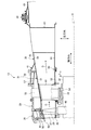
図6は、本実施形態のガスタービンの全体構成を表す概略図である。 FIG. 6 is a schematic diagram illustrating the overall configuration of the gas turbine of the present embodiment.
本実施形態において、図6に示すように、ガスタービン10は、圧縮機11と燃焼器12とタービン13により構成されている。このガスタービン10は、ロータ(回転軸)32の外側に軸心Cの方向(以下、軸方向)に沿って圧縮機11とタービン13が配置されると共に、圧縮機11とタービン13との間に複数の燃焼器12が配置されている。そして、ガスタービンは、同軸上に図示しない発電機(電動機)が連結され、発電可能となっている。
In this embodiment, as shown in FIG. 6, the
圧縮機11は、空気を取り込む空気取入口20を有し、圧縮機車室21内に入口案内翼(IGV:Inlet Guide Vane)22が配設されると共に、複数の静翼23と複数の動翼24が空気の流動方向(軸心C方向)に交互に配設されており、その外側に抽気室25が設けられている。この圧縮機11は、空気取入口20から取り込まれた空気を圧縮することで高温・高圧の圧縮空気を生成し、燃焼器12に供給する。圧縮機11は、同軸上に連結された電動機により起動可能となっている。
The
燃焼器12は、圧縮機11で圧縮されてタービン車室26に溜められた高温・高圧の圧縮空気と燃料が供給され、燃焼することで、燃焼ガスを生成する。タービン13は、タービン車室26内に複数の静翼27と複数の動翼28が燃焼ガスの流動方向(軸方向)に交互に配設されている。そして、このタービン車室26は、下流側に排気車室29を介して排気室30が配設されている。この排気室30は、タービン13に連結する排気ディフューザ31を有している。タービン13は、燃焼器12からの燃焼ガスにより駆動し、同軸上に連結された発電機を駆動可能となっている。
The
圧縮機11と燃焼器12とタービン13は、内部に排気室30の中心部を貫通するように軸方向に沿ったロータ32が配置されている。ロータ32は、圧縮機11側の端部が軸受部33により回転可能に支持されると共に、排気室30側の端部が軸受部34により回転可能に支持されている。そして、ロータ32は、圧縮機11にて、各動翼24が装着されたディスクが複数重ねられて固定されている。また、ロータ32は、タービン13にて、各動翼28が装着されたディスクが複数重ねられて固定されている。そして、ロータ32は、空気取入口20側の端部に発電機の駆動軸が連結されている。
In the
そして、このガスタービン10は、圧縮機11の圧縮機車室21が脚部35に支持され、タービン13のタービン車室26が脚部36により支持され、排気室30が脚部37により支持されている。
In the
そのため、圧縮機11にて、空気取入口20から取り込まれた空気が、入口案内翼22、複数の静翼23と動翼24を通過して圧縮されることで高温・高圧の圧縮空気となる。燃焼器12にて、この圧縮空気に対して所定の燃料が供給され、燃焼する。タービン13にて、燃焼器12で生成された高温・高圧の燃焼ガスが、タービン13における複数の静翼27と動翼28を通過することでロータ32を駆動回転し、このロータ32に連結された発電機を駆動する。そして、タービン13を駆動した燃焼ガスは、排気ガスとして大気に放出される。
Therefore, the air taken in from the
このように構成されたガスタービン10にて、円筒形状をなす排気部材として、タービン車室26と排気車室29と排気室30が設けられている。
In the
図1は、本実施形態のガスタービンの排気部材を表す断面図である。なお、ガスタービン10における燃焼ガス(排気ガス)Gの流動方向は、ロータ32の軸方向(軸心Cの方向)に沿うものであり、以下の説明では、燃焼ガスGの流動方向の上流側を前側(前方)と称し、燃焼ガスの流動方向の下流側(後方)を後側と称する。
FIG. 1 is a cross-sectional view illustrating an exhaust member of the gas turbine according to the present embodiment. The flow direction of the combustion gas (exhaust gas) G in the
図1に示すように、タービン車室26は、円筒形状をなし、複数の静翼27と動翼28が軸方向に沿って交互に配設されており、燃焼ガスGの流動方向の下流側に排気車室29が配置されている。排気車室29は、円筒形状をなし、燃焼ガスGの流動方向の下流側に排気室30が配置されている。この排気室30は、円筒形状をなしている。そして、排気車室29と排気室30は、熱伸びを吸収可能な排気室サポート41により連結されている。また、排気室30は、前部排気室42と後部排気室43とにより構成され、前部排気室42と後部排気室43は、熱伸びを吸収可能なエキスパンションジョイント(伸縮継手)44により連結されている。
As shown in FIG. 1, the
タービン車室26は、内周部に燃焼ガスGの流動方向に所定間隔をあけて翼環45が固定されている。ロータ32は、外周部に複数のディスク48が一体に連結されてなり、動翼28は、周方向に均等間隔で配置され、基端部がディスク48の外周部に固定されている。
In the
静翼27は、周方向に均等間隔で配置され、径方向における内側の端部がリング形状をなす内側シュラウド49に固定され、径方向における外側の端部がリング形状をなす外側シュラウド50に固定されている。外側シュラウド50は、翼環45に支持されている。
The
排気車室29は、その内側に円筒形状をなす排気ディフューザ31が配置されている。この排気ディフューザ31は、円筒形状をなす外側ディフューザ51と内側ディフューザ52がストラットシールド53により連結されて構成される。このストラットシールド53は、円筒形状または楕円筒形状などの中空構造をなし、径方向に対して周方向に所定角度だけ傾斜しており、排気ディフューザ31の周方向に均等間隔で複数設けられている。そして、内側ディフューザ52は、内周部に軸受箱54により軸受部34が支持され、軸受34によりロータ32が回転可能に支持されている。ストラットシールド53は、内部にストラット55が配設されている。ストラット55は、径方向における内側の端部が軸受箱54に固定され、径方向における外側の端部が排気車室29に固定されている。なお、ストラットシールド53は、外部から内部の空間に冷却空気が供給可能となっており、排気ディフューザ31を冷却することができる。
An
排気ディフューザ31の外側ディフューザ51は、後端部がディフューザサポート57により排気車室29に連結されている。ディフューザサポート57は、短冊形状をなし、軸方向に沿って延設されると共に、周方向に複数所定の間隔で並設されている。このディフューザサポート57は、一端部が排気車室29に締結され、他端部が外側ディフューザ51に締結されている。ディフューザサポート57は、排気車室29と排気ディフューザ31との間で、温度差により熱伸びが発生したときに変形してその熱伸びを吸収可能となっている。排気車室29は、ディフューザサポート57を外側から被覆するように設けられており、排気車室29の後端部と外側ディフューザ51の後端部との間にガスシール58が設けられている。
The
排気室30の前部排気室42は、円筒形状をなす外筒59と内筒60が中空ストラット61により連結されて構成され、この中空ストラット61は、円筒形状や楕円筒状などの中空構造をなし、排気室30の周方向に均等間隔で複数設けられている。中空ストラット61は、排気室30の外筒59側において開口しており、中空ストラット61の内部は、大気に連通している。
The
排気車室29の後端部と前部排気室42は、排気室サポート41により連結されている。排気ディフューザ31と前部排気室42とは、外側ディフューザ51の後端部と外筒59の前端部が近接して対向すると共に、内側ディフューザ52の後端部と内筒60の前端部とが接近して対向している。外側ディフューザ51と外筒59は、燃焼ガスGの流動方向の下流側に向けて拡径しているが、内側ディフューザ52と内筒60は、燃焼ガスGの流動方向の下流側に向けて同径となっている。排気室サポート41は、短冊形状をなし、軸方向に沿って延設されると共に、周方向に複数所定の間隔で並設されている。また、排気室サポート41は、前端部が排気車室29に締結され、後端部が前部排気室42の外筒59に締結されている。
The rear end portion of the
また、内側ディフューザ52の後端部と内筒60の前端部との間にシール部材64が設けられている。排気室サポート41は、排気車室29と排気室30との間で温度差により熱伸びが発生したとき、変形することでその熱伸びを吸収可能となっている。また、シール部材64は、排気車室29と排気室30との間で温度差により熱伸びが発生したとき、軸方向に相対的に移動することでその熱伸びを吸収可能となっている。
A
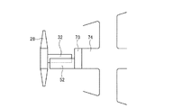
ここで、このシール部材64について詳細に説明する。図2は、内側ディフューザと内筒との連結部に設けられるシール部材を表す断面図、図3は、図2のIII−III断面図、図4は、図2のIV−IV断面図、図5は、内側ディフューザとシール部材との連結部を表す断面図である。
Here, the
図2から図4に示すように、内側ディフューザ(第1ケーシング)52は、周方向に複数分割(本実施形態では、2分割)された上部ケーシング71と下部ケーシング(図示略)から構成され、水平部の分割面に設けられたフランジ部が締結ボルトに締結されることで円筒形状をなしている。内筒(第4ケーシング)60は、周方向に複数分割(本実施形態では、2分割)された上部ケーシング72と下部ケーシング(図示略)から構成され、水平部の分割面に設けられたフランジ部が締結ボルトに締結されることで円筒形状をなしている。シール部材64は、第1シールハウジング(第2ケーシング)73と、第2シールハウジング(第3ケーシング)74と、支持連結部75とから構成されている。
As shown in FIGS. 2 to 4, the inner diffuser (first casing) 52 includes an
第1シールハウジング73は、円筒形状をなして周方向に一体形成され、周方向に分離可能な分割面のない構成であり、軸方向における前端部が内側ディフューザ52の軸方向における後端部に連結されている。第2シールハウジング74は、円筒形状をなして周方向に一体形成され、周方向に分離可能な分割面のない構成であり、軸方向における後端部が内筒60の軸方向における前端部に連結されている。支持連結部75は、第1シールハウジング73の後端部と第2シールハウジング74の前端部とを径方向に拘束し、軸方向に相対的に移動可能に支持するものである。
The
図4及び図5に示すように、内側ディフューザ52は、後端部に径方向における内側に折曲する第1フランジ部81が周方向に沿って設けられ、第1フランジ部81に周方向に所定間隔(好ましくは、等間隔)で複数の貫通孔81aが形成されている。第1シールハウジング73は、前端部に径方向における内側に折曲する第2フランジ部82が周方向に沿って設けられ、第2フランジ部82に周方向に所定間隔(好ましくは、等間隔)で複数の切欠部82aが形成されている。切欠部82aは、貫通孔81aより大径の円弧を有し、第2フランジ部82の内周側に開放されている。また、貫通孔81aと切欠部82aは、周方向における同位置に形成されている。
As shown in FIGS. 4 and 5, the
内側ディフューザ52の第1フランジ部81は、第1シールハウジング73の第2フランジ部82に密着し、第1フランジ部81の各貫通孔81aと第2フランジ部82の各切欠部82aが一致している。締結ボルト83は、内側ディフューザ52側から貫通孔81aを貫通すると共に切欠部82aに挿通した後、押えリング84及び皿ばね(付勢部材)85が介装され、先端ねじ部83aに締結ナット86が螺合している。ここで、締結ボルト83は、大径部83bが貫通孔81aを嵌合する一方、切欠部82aに遊嵌している。そのため、内側ディフューザ52と第1シールハウジング73は、第1フランジ部81と第2フランジ部82が皿ばね85の付勢力により密着すると共に、締結ボルト83の大径部83bと切欠部82aとの間の隙間だけ、皿ばね85の付勢力に抗して径方向と周方向に相対移動可能となる。
The
また、第1シールハウジング73は、第2フランジ部82における前面部に周方向に沿って溝部82bが形成され、この溝部82bにシールパッキン87が設けられている。そのため、内側ディフューザ52の第1フランジ部81が第1シールハウジング73の第2フランジ部82に密着すると、第2フランジ部82のシールパッキン87が潰れて第1フランジ部81に押圧し、内側ディフューザ52と第1シールハウジング73とが隙間なく連結される。
In the
また、図2から図4に示すように、内筒60は、前端部に径方向における内側に折曲する第4フランジ部91が周方向に沿って設けられ、第4フランジ部91に周方向に所定間隔(好ましくは、等間隔)で複数の貫通孔91aが形成されている。また、内筒60は、第4フランジ部91の前面部側に凸部91bが周方向に沿って形成されている。第2シールハウジング74は、後端部に径方向における内側に折曲する第3フランジ部92が周方向に沿って設けられ、第3フランジ部92に周方向に所定間隔(好ましくは、等間隔)で複数のねじ穴部92aが形成されている。貫通孔91aとねじ穴部92aは、周方向における同位置に形成されている。また、第2シールハウジング74は、第3フランジ部92の後面部側に凹部92bが周方向に沿って形成されている。
As shown in FIGS. 2 to 4, the
内筒60の第4フランジ部91は、第2シールハウジング74の第3フランジ部92に密着し、第4フランジ部91の各貫通孔91aと第3フランジ部92の各ねじ穴部92aが一致している。このとき、内筒60における第4フランジ部91の凸部91bが第2シールハウジング74における第3フランジ部92の凹部92bに嵌合することで、内筒60と第2シールハウジング74とにおける径方向の位置決めがなされる。締結ボルト93は、内筒60側から貫通孔91aを貫通してねじ部93aがねじ穴部92aに螺合している。そのため、内筒60と第2シールハウジング74は、第4フランジ部91と第3フランジ部92が密着して固定されることとなる。
The
また、第1シールハウジング73は、後部に周方向に沿って溝形状をなす嵌合凹部101が設けられている。一方、第2シールハウジング74は、前部に周方向に沿ってフランジ形状をなす嵌合凸部102が設けられている。第2シールハウジング74の嵌合凸部102は、第1シールハウジング73の嵌合凹部101に嵌合し、各シールハウジング73,74は、軸方向及び周方向に沿って互いに相対移動可能に連結されている。なお、第1、第2シールハウジング73,74は、互いに軸方向及び周方向に沿って移動可能であることから、両者の間に径方向の微小隙間が確保されている。支持連結部75は、この嵌合凹部101と嵌合凸部102により構成される。なお、支持連結部75は嵌合凸部102と嵌合凹部101との組合せにより構成されるものに限られない。例えば、単に第1シールハウジング73の内周に第2シールハウジング74の外周が嵌めあわされるものや、その逆であってもよい。
Further, the
第1シールハウジング73は、嵌合凹部101の内側にフランジ部103が周方向に沿って設けられ、フランジ部103に周方向に所定間隔(好ましくは、等間隔)で複数の貫通孔103aが形成されると共に、各貫通孔103aの端部に大径部103bが形成されている。第3シールハウジング104は、リング形状をなし、外側にフランジ部105が周方向に沿って設けられると共に、周方向に所定間隔(好ましくは、等間隔)で複数の貫通孔104aが形成されると共に、各貫通孔104aの端部にボス部104bが形成されている。なお、第3シールハウジング104は、周方向に複数分割(本実施形態では、4分割)された複数のハウジングから構成され、組付性を考慮した構成としたが、周方向に一体形成された構成としてもよい。
In the
シールパッキン(シール部材)106は、支持連結部75における嵌合凹部101と嵌合凸部102との径方向における微小隙間をシールするものである。シールパッキン106は、リング形状をなすと共に矩形断面形状をなし、第1シールハウジング73のフランジ部103と第3シールハウジング104のフランジ部105との間に介装されている。
The seal packing (seal member) 106 seals a minute gap in the radial direction between the fitting
第1シールハウジング73のフランジ部103は、第3シールハウジング104が密着し、各貫通孔103aと各貫通孔104aが一致している。このとき、ボス部104bが大径部103bに嵌合することで、第1シールハウジング73と第3シールハウジング104とにおける径方向及び周方向の位置決めがなされる。また、第1シールハウジング73のフランジ部103と第3シールハウジング104のフランジ部105との間にシールパッキン106が介装されている。締結ボルト107は、第1シールハウジング73側から貫通孔103a及び貫通孔104aを貫通してねじ部107aに締結ナット108が螺合している。そのため、第1シールハウジング73のフランジ部103と第3シールハウジング104が密着して固定される。このとき、シールパッキン106が軸方向に潰されて径方向の外側に突出して変形することで、シールパッキン106が第2シールハウジング74の内周面を押圧し、嵌合凹部101と嵌合凸部102との径方向における微小隙間がシールされる。
The
また、図1に示すように、シール部材64は、ロータ32の後端部より後方に配置されている。具体的に、シール部材64を構成する第1シールハウジング73の前端部は、ロータ32の後端部より後方に配置されている。即ち、第1シールハウジング73の前端部とロータ32(軸受箱54)の後端部とは、距離Lだけずれている。但し、第1シールハウジング73と第2シールハウジング74とは、支持連結部75により軸方向に相対的に移動可能であり、少なくとも第1シールハウジング73が後方に移動したとき、第1シールハウジング73の前端部がロータ32の後端部より後方に配置されていればよい。
Further, as shown in FIG. 1, the
このように構成されたガスタービン10における内部の構造物をメンテナンスするとき、タービン車室26の上部ケーシング、排気車室29の上部ケーシング、排気室30の上部ケーシング、外側ディフューザ51の上部ケーシング、内側ディフューザ52の上部ケーシング71を取外して行う。但し、シール部材64を構成する第1シールハウジング73、第2シールハウジング74、支持連結部75、第3シールハウジング104などは取外さずにそのままとする。
When maintaining the internal structure of the
ガスタービン10にて、内部を燃焼ガス(排気ガス)Gが流動するとき、排気ディフューザ31(外側ディフューザ51と内側ディフューザ52)や前部排気室42(外筒59と内筒60)が加熱され、熱伸びが発生する。そして、この熱伸びは、各部材の軸方向、径方向、周方向に対して発生し、各サポート41,57やシール部材64の支持連結部75により吸収される。但し、発生した熱伸びにより各部材で塑性変形が発生し、ガスタービンの停止後に、塑性ひずみが残存することがある。そのため、排気ディフューザ31と前部排気室42で塑性ひずみ量が相違することから、かじりつきが発生するおそれがある。
When combustion gas (exhaust gas) G flows in the
ところが、本実施形態では、シール部材64を構成する第1シールハウジング73及び第2シールハウジング74が周方向に一体の形状をなしていることから、締結ボルトによる連結部がない。そのため、塑性ひずみ自体の発生量が少ない上、塑性ひずみが発生したとしても真円形状が維持される。そのため、支持連結部75にて、第1シールハウジング73と第2シールハウジング74とのかじりつきが生じず、円滑な軸方向移動及び周方向移動が確保される。また、第1シールハウジング73は、各切欠部82aが貫通孔81a(締結ボルト83の大径部83b)より大径の円弧を有していることから、内側ディフューザ52の上部ケーシング71が微小変形しても、容易に取外すことができ、また、容易に取付けることができる。
However, in the present embodiment, since the
更に、第1シールハウジング73や第2シールハウジング74を取外さなくとも、第1シールハウジング73の前端部がロータ32の後端部より後方に配置されているため、第1シールハウジング73に対して、内側ディフューザ52の上部ケーシング71を取外した後、容易にロータ32を上昇して取外すことができ、また、容易に下降して取付けることができる。
Further, the front end portion of the
なお、上述の説明では、シール部材64を構成する第1シールハウジング73、第2シールハウジング74、支持連結部75、第3シールハウジング104などを取外さずにそのままとしたが、その一部または全部を取外してもよい。このとき、支持連結部75にて、第1シールハウジング73と第2シールハウジング74との円滑な軸方向移動及び周方向移動が確保されていることから、第1シールハウジング73と第2シールハウジング74との分離を容易に行うことができる。
In the above description, the
このように本実施形態のガスタービンの排気部材にあっては、円筒形状をなして周方向に複数分割される内側ディフューザ52と、円筒形状をなして周方向に一体構成されて前端部が内側ディフューザ52の後端部に連結される第1シールハウジング73と、円筒形状をなして周方向に一体構成されて前端部が第1シールハウジング73の後端部に連結される第2シールハウジング74と、第1シールハウジング73の後端部と第2シールハウジング74の前端部とを軸方向に移動可能に支持する支持連結部75とを設けている。
As described above, in the exhaust member of the gas turbine according to the present embodiment, the
従って、周方向に分割される内側ディフューザ52に周方向に一体構成される第1シールハウジング73が連結され、この第1シールハウジング73に周方向に一体構成される第2シールハウジング74が支持連結部75により軸方向に移動可能に連結されることとなる。ガスタービン10の運転時に、内側ディフューザ52と各シールハウジング73,74が内部に流動する燃焼ガスにより加熱され、軸方向及び径方向に異なる量の熱伸びが発生すると、異なる量の塑性変形が内部応力として残存するおそれがある。
Therefore, the
しかし、各シールハウジング73,74は、周方向に一体構成されていることから、冷却後には元の形状に戻ることとなり、両者の連結部が嵌着することはなく、支持連結部による軸方向の円滑な移動が可能となる。そのため、内側ディフューザ52の上部ケーシング71を容易に取外すことができると共に、各シールハウジング73,74を容易に分離することができ、上部ケーシング71の取外しと取付けを容易としてメンテナンス性の向上を図ることができる。
However, since the
図7を参照しながら説明する。図7−1は、本実施形態のガスタービンの排気部材を概念的に表す概略図、図7−2は、本実施形態の排気室メンテナンス方法を概念的に表す概略図である。 This will be described with reference to FIG. FIG. 7-1 is a schematic diagram conceptually showing an exhaust member of the gas turbine of the present embodiment, and FIG. 7-2 is a schematic diagram conceptually showing an exhaust chamber maintenance method of the present embodiment.
本実施形態のガスタービンの排気部材では、第1シールハウジング73の前端部は、ロータ32の後端部より後方に配置している。この場合、第1シールハウジング73が支持連結部75により第2シールハウジング74側に移動したとき、第1シールハウジング73の前端部がロータ32の後端部より後方に配置される(図7−1参照)。従って、内側ディフューザ52の上部ケーシング71を取外した後、第1シールハウジング73が邪魔することなく、ロータ32を容易に上方に移動して取外すことができる(図7−2参照)。また、内側ディフューザ52の上部ケーシング71を取外した後、ロータ32が邪魔することなく、第1シールハウジング73を容易に上方に移動して取外すことができる。また、支持連結部75による各シールハウジング73,74の移動ストロークを考慮して第1シールハウジング73の位置を設定しており、メンテナンス性の向上を図ることができる。
In the exhaust member of the gas turbine of the present embodiment, the front end portion of the
本実施形態のガスタービンの排気部材では、第2シールハウジング74の後端部に、円筒形状をなして周方向に複数分割された前部排気室42の内筒60の前端部を連結している。従って、第2シールハウジング74に対して内筒60の上部側を取外すことで、各シールハウジング73,74を取外すことなく、容易に内部のメンテナンスを行うことができる。
In the exhaust member of the gas turbine of the present embodiment, the front end portion of the
本実施形態のガスタービンの排気部材では、支持連結部75に第1シールハウジング73と第2シールハウジング74との隙間をシールするリング形状をなすシールパッキン106を設けている。従って、シールパッキン106により支持連結部75からの燃焼ガスの漏洩を防止することができる。
In the exhaust member of the gas turbine of the present embodiment, the
本実施形態のガスタービンの排気部材では、内側ディフューザ52の後端部にリング形状をなす第1フランジ部81を設け、第1シールハウジング73の前端部にリング形状をなす第2フランジ部82を設け、第1フランジ部81に複数の貫通孔81aを周方向に沿って形成し、第2フランジ部82に径方向に沿う複数の切欠部82aを周方向に沿って形成し、締結ボルト83が貫通孔81aに貫通すると共に切欠部82aに挿通し、切欠部82aに近接して皿ばね85を介装し、締結ボルト83の先端ねじ部83aに締結ナット86を螺合している。
In the exhaust member of the gas turbine of this embodiment, a
従って、内側ディフューザ52と第1シールハウジング73との間で、径方向における熱伸び差が発生すると、第1フランジ部81と第2フランジ部82が径方向にずれ、締結ボルト83に対して径方向のせん断力が作用する。しかし、締結ボルト83は、十分な強度を確保することができる大径部83bが貫通孔81aに貫通していることから、この締結ボルト83の破断を抑制することができる。即ち、内側ディフューザ52と第1シールハウジング73が径方向にずれたとき、せん断力が締結ボルト83の大径部83bに作用するが、締結ボルト83は、大径部83bを十分に太くすることが可能であるため、この締結ボルト83の破断を抑制することができる。
Therefore, when a difference in thermal expansion in the radial direction occurs between the
なお、上述した実施形態にて、内筒60を周方向に複数分割した上部ケーシング72と下部ケーシングとから構成したが、周方向に一体形成されたリング部材により構成してもよい。
In the above-described embodiment, the
また、上述した実施形態にて、第1シールハウジング73の第2フランジ部82に複数の切欠部82aを周方向に所定間隔で形成したが、切欠部82aに代えて、径方向に沿う長穴や貫通孔81aより大径の貫通孔としてもよい。
In the above-described embodiment, the plurality of
また、上述した実施形態にて、内側ディフューザ52の第1フランジ部81に貫通孔81aを形成し、第1シールハウジング73の第2フランジ部82に切欠部82aを形成し、締結ボルト83が内側ディフューザ52側から貫通孔81aと切欠部82aを貫通して皿ばね(付勢部材)85を介装し、先端ねじ部83aに締結ナット86を螺合したが、この構成に限定されるものではない。例えば、内側ディフューザ52の第1フランジ部81に切欠部(または、長穴)を形成し、第1シールハウジング73の第2フランジ部82に貫通孔を形成し、締結ボルトが第1シールハウジング73側から貫通孔と切欠部を貫通して皿ばね(付勢部材)を介装し、先端ねじ部に締結ナットを螺合してもよい。また、皿ばね(付勢部材)は、第1フランジ部81と第2フランジ部82の間であってもよい。
Further, in the above-described embodiment, the through
また、上述した実施形態にて、支持連結部75として、第1シールハウジング73に嵌合凹部101を設け、第2シールハウジング74に嵌合凸部102を形成したが、第1シールハウジング73に嵌合凸部を設け、第2シールハウジング74に嵌合凹部を形成してもよい。また、支持連結部75は、第1シールハウジング73と第2シールハウジング74を軸方向に移動可能に連結するものであり、嵌合凹部101と嵌合凸部102に限るものではない。
In the embodiment described above, the
また、上述した実施形態にて、冷却される排気ディフューザ31と冷却されない前部排気室42とで、熱伸び量(塑性ひずみ量)が相違するとしたが、排気ディフューザ31と前部排気室42とで異なる材料を使用しても、両者の塑性ひずみ量が相違するため、この構成であっても、本発明は有効的である。
In the above-described embodiment, the amount of thermal expansion (plastic strain amount) is different between the cooled
11 圧縮機
12 燃焼器
13 タービン
21 圧縮機車室
26 タービン車室
27 静翼
28 動翼
29 排気車室
30 排気室
31 排気ディフューザ
32 ロータ(回転軸)
42 前部排気室
43 後部排気室
51 外側ディフューザ
52 内側ディフューザ(第1ケーシング)
53 ストラットシールド
55 ストラット
59 外筒
60 内筒(第4ケーシング)
61 中空ストラット
64 シール部材
71,72 上部ケーシング
73 第1シールハウジング(第2ケーシング)
74 第2シールハウジング(第3ケーシング)
75 支持連結部
81a 貫通孔
82a 切欠部
83 締結ボルト
85 皿ばね(付勢部材)
86 締結ナット
101 嵌合凹部
102 嵌合凸部
103 第2シールハウジング
106 シールパッキン(シール部材)
DESCRIPTION OF
42
53
61
74 Second seal housing (third casing)
75
86
Claims (6)
円筒形状をなして周方向に一体構成されて軸方向における前端部が前記排気ディフューザの軸方向における後端部に連結される第1シールハウジングと、
円筒形状をなして周方向に一体構成されて軸方向における前端部が前記第1シールハウジングの軸方向における後端部に連結される第2シールハウジングと、
前記第1シールハウジングの後端部と前記第2シールハウジングの前端部とを軸方向に移動可能に支持する支持連結部と、
を有することを特徴とするガスタービンの排気部材。 An exhaust diffuser having a cylindrical shape and divided into a plurality of circumferential directions;
A first seal housing having a cylindrical shape integrally formed in the circumferential direction and having a front end portion in the axial direction connected to a rear end portion in the axial direction of the exhaust diffuser ;
A second seal housing having a cylindrical shape integrally formed in the circumferential direction and having a front end portion in the axial direction connected to a rear end portion in the axial direction of the first seal housing ;
A support connecting portion for movably supporting the front end of the rear portion and the second seal housing of the first seal housing in the axial direction,
An exhaust member for a gas turbine, comprising:
円筒形状をなして周方向に一体構成されて軸方向における前端部が前記排気ディフューザの軸方向における後端部に連結される第1シールハウジングと、
円筒形状をなして周方向に一体構成されて軸方向における前端部が前記第1シールハウジングの軸方向における後端部に連結される第2シールハウジングと、
前記第1シールハウジングの後端部と前記第2シールハウジングの前端部とを軸方向に移動可能に支持する支持連結部と、を有し、
前記第1シールハウジングの前端部が前記排気ディフューザ内に配置される回転軸の後端部より後方に配置される排気室メンテナンス方法であって、
前記排気ディフューザの分割部の締結を解除する工程と、
前記排気ディフューザと前記第1シールハウジングの締結を解除する工程と、
前記排気ディフューザの分割部を取外す工程と、
を有することを特徴とする排気室メンテナンス方法。
An exhaust diffuser having a cylindrical shape and divided into a plurality of circumferential directions;
A first seal housing having a cylindrical shape integrally formed in the circumferential direction and having a front end portion in the axial direction connected to a rear end portion in the axial direction of the exhaust diffuser ;
A second seal housing having a cylindrical shape integrally formed in the circumferential direction and having a front end portion in the axial direction connected to a rear end portion in the axial direction of the first seal housing ;
Anda support connecting portion for movably supporting the front end of the rear portion and the second seal housing of the first seal housing in the axial direction,
An exhaust chamber maintenance method in which a front end portion of the first seal housing is disposed behind a rear end portion of a rotating shaft disposed in the exhaust diffuser ,
Releasing the fastening of the split portion of the exhaust diffuser ;
Releasing the fastening of the exhaust diffuser and the first seal housing ;
Removing the split part of the exhaust diffuser ;
An exhaust chamber maintenance method characterized by comprising:
Priority Applications (7)
| Application Number | Priority Date | Filing Date | Title |
|---|---|---|---|
| JP2014170775A JP6441611B2 (en) | 2014-08-25 | 2014-08-25 | Gas turbine exhaust member and exhaust chamber maintenance method |
| CN201811387486.3A CN109630218B (en) | 2014-08-25 | 2015-07-03 | Exhaust component of a gas turbine |
| KR1020177002300A KR101955830B1 (en) | 2014-08-25 | 2015-07-03 | Gas turbine exhaust member, and exhaust chamber maintenance method |
| CN201580041787.9A CN106574516B (en) | 2014-08-25 | 2015-07-03 | Exhaust chamber maintaining method |
| PCT/JP2015/069319 WO2016031393A1 (en) | 2014-08-25 | 2015-07-03 | Gas turbine exhaust member, and exhaust chamber maintenance method |
| DE112015003891.4T DE112015003891T5 (en) | 2014-08-25 | 2015-07-03 | Gas turbine exhaust element and exhaust chamber maintenance method |
| US15/329,095 US10865658B2 (en) | 2014-08-25 | 2015-07-03 | Gas turbine exhaust member, and exhaust chamber maintenance method |
Applications Claiming Priority (1)
| Application Number | Priority Date | Filing Date | Title |
|---|---|---|---|
| JP2014170775A JP6441611B2 (en) | 2014-08-25 | 2014-08-25 | Gas turbine exhaust member and exhaust chamber maintenance method |
Publications (3)
| Publication Number | Publication Date |
|---|---|
| JP2016044630A JP2016044630A (en) | 2016-04-04 |
| JP2016044630A5 JP2016044630A5 (en) | 2017-07-27 |
| JP6441611B2 true JP6441611B2 (en) | 2018-12-19 |
Family
ID=55399297
Family Applications (1)
| Application Number | Title | Priority Date | Filing Date |
|---|---|---|---|
| JP2014170775A Active JP6441611B2 (en) | 2014-08-25 | 2014-08-25 | Gas turbine exhaust member and exhaust chamber maintenance method |
Country Status (6)
| Country | Link |
|---|---|
| US (1) | US10865658B2 (en) |
| JP (1) | JP6441611B2 (en) |
| KR (1) | KR101955830B1 (en) |
| CN (2) | CN106574516B (en) |
| DE (1) | DE112015003891T5 (en) |
| WO (1) | WO2016031393A1 (en) |
Families Citing this family (13)
| Publication number | Priority date | Publication date | Assignee | Title |
|---|---|---|---|---|
| US20160281533A1 (en) * | 2015-03-27 | 2016-09-29 | Dresser-Rand Company | Mounting assembly for a bundle of a compressor |
| FR3040737B1 (en) * | 2015-09-04 | 2017-09-22 | Snecma | PROPULSIVE ASSEMBLY WITH DISMANTLING CASTER PARTS |
| JP7032279B2 (en) * | 2018-10-04 | 2022-03-08 | 本田技研工業株式会社 | Gas turbine engine |
| US10822964B2 (en) * | 2018-11-13 | 2020-11-03 | Raytheon Technologies Corporation | Blade outer air seal with non-linear response |
| US10920618B2 (en) | 2018-11-19 | 2021-02-16 | Raytheon Technologies Corporation | Air seal interface with forward engagement features and active clearance control for a gas turbine engine |
| US10934941B2 (en) | 2018-11-19 | 2021-03-02 | Raytheon Technologies Corporation | Air seal interface with AFT engagement features and active clearance control for a gas turbine engine |
| US11391179B2 (en) | 2019-02-12 | 2022-07-19 | Pratt & Whitney Canada Corp. | Gas turbine engine with bearing support structure |
| US11346249B2 (en) | 2019-03-05 | 2022-05-31 | Pratt & Whitney Canada Corp. | Gas turbine engine with feed pipe for bearing housing |
| US11460037B2 (en) | 2019-03-29 | 2022-10-04 | Pratt & Whitney Canada Corp. | Bearing housing |
| CN110374697B (en) * | 2019-07-19 | 2021-09-03 | 中国航发沈阳发动机研究所 | Adjusting device for controlling axial distance between rotor and stator of engine |
| CN112761743B (en) * | 2020-12-29 | 2022-08-16 | 杭州汽轮动力集团有限公司 | Gas turbine exhaust diffuser seal structure |
| CN113482728B (en) * | 2021-06-30 | 2023-04-18 | 东阳市盛丰机械有限公司 | Self-compensating gas turbine cylinder sealing device |
| CN115370433A (en) * | 2022-08-29 | 2022-11-22 | 浙江燃创透平机械股份有限公司 | Exhaust cylinder structure of gas turbine |
Family Cites Families (21)
| Publication number | Priority date | Publication date | Assignee | Title |
|---|---|---|---|---|
| GB1335145A (en) * | 1972-01-12 | 1973-10-24 | Rolls Royce | Turbine casing for a gas turbine engine |
| JP2002013401A (en) * | 2000-06-29 | 2002-01-18 | Yanmar Diesel Engine Co Ltd | Exhauster of gas turbine |
| FR2891300A1 (en) * | 2005-09-23 | 2007-03-30 | Snecma Sa | DEVICE FOR CONTROLLING PLAY IN A GAS TURBINE |
| JP2009024631A (en) * | 2007-07-20 | 2009-02-05 | Hitachi Ltd | Gas turbine facility |
| JP5118496B2 (en) | 2008-01-10 | 2013-01-16 | 三菱重工業株式会社 | Gas turbine exhaust structure and gas turbine |
| US8800300B2 (en) * | 2008-02-27 | 2014-08-12 | Mitsubishi Heavy Industries, Ltd. | Connection structure of exhaust chamber, support structure of turbine, and gas turbine |
| JP5161629B2 (en) * | 2008-03-28 | 2013-03-13 | 三菱重工業株式会社 | Turbine support structure and gas turbine |
| JP5047000B2 (en) * | 2008-02-27 | 2012-10-10 | 三菱重工業株式会社 | Exhaust chamber connection structure and gas turbine |
| JP5010499B2 (en) | 2008-02-28 | 2012-08-29 | 三菱重工業株式会社 | Gas turbine and gas turbine maintenance inspection method |
| JP4969500B2 (en) * | 2008-03-28 | 2012-07-04 | 三菱重工業株式会社 | gas turbine |
| JP2011038491A (en) * | 2009-08-18 | 2011-02-24 | Mitsubishi Heavy Ind Ltd | Turbine exhaust structure and gas turbine |
| JP2011169246A (en) * | 2010-02-19 | 2011-09-01 | Mitsubishi Heavy Ind Ltd | Gas turbine casing structure |
| US20120224960A1 (en) * | 2010-12-30 | 2012-09-06 | Raymond Ruiwen Xu | Gas turbine engine case |
| JP5342579B2 (en) * | 2011-02-28 | 2013-11-13 | 三菱重工業株式会社 | Stator blade unit of rotating machine, method of manufacturing stator blade unit of rotating machine, and method of coupling stator blade unit of rotating machine |
| JP5726013B2 (en) * | 2011-08-05 | 2015-05-27 | 三菱日立パワーシステムズ株式会社 | Expansion joint, gas turbine equipped with the same, and expansion joint mounting method |
| US9206705B2 (en) | 2012-03-07 | 2015-12-08 | Mitsubishi Hitachi Power Systems, Ltd. | Sealing device and gas turbine having the same |
| CN105065811B (en) * | 2012-06-25 | 2017-05-24 | 株式会社久保田 | Pressing ring, coupling, and valve |
| EP2679780B8 (en) | 2012-06-28 | 2016-09-14 | General Electric Technology GmbH | Diffuser for the exhaust section of a gas turbine and gas turbine with such a diffuser |
| US20140248146A1 (en) * | 2012-08-31 | 2014-09-04 | United Technologies Corporation | Attachment apparatus for ceramic matrix composite materials |
| WO2014068355A1 (en) * | 2012-10-30 | 2014-05-08 | General Electric Company | Gas turbine engine exhaust system and corresponding method for accessing turbine buckets |
| US9587519B2 (en) * | 2013-11-22 | 2017-03-07 | Siemens Energy, Inc. | Modular industrial gas turbine exhaust system |
-
2014
- 2014-08-25 JP JP2014170775A patent/JP6441611B2/en active Active
-
2015
- 2015-07-03 WO PCT/JP2015/069319 patent/WO2016031393A1/en active Application Filing
- 2015-07-03 KR KR1020177002300A patent/KR101955830B1/en active IP Right Grant
- 2015-07-03 CN CN201580041787.9A patent/CN106574516B/en active Active
- 2015-07-03 US US15/329,095 patent/US10865658B2/en active Active
- 2015-07-03 DE DE112015003891.4T patent/DE112015003891T5/en active Pending
- 2015-07-03 CN CN201811387486.3A patent/CN109630218B/en active Active
Also Published As
| Publication number | Publication date |
|---|---|
| CN109630218B (en) | 2021-08-27 |
| US10865658B2 (en) | 2020-12-15 |
| CN106574516B (en) | 2019-05-14 |
| KR101955830B1 (en) | 2019-03-07 |
| WO2016031393A1 (en) | 2016-03-03 |
| CN106574516A (en) | 2017-04-19 |
| US20170284225A1 (en) | 2017-10-05 |
| JP2016044630A (en) | 2016-04-04 |
| CN109630218A (en) | 2019-04-16 |
| KR20170020523A (en) | 2017-02-22 |
| DE112015003891T5 (en) | 2017-05-11 |
Similar Documents
| Publication | Publication Date | Title |
|---|---|---|
| JP6441611B2 (en) | Gas turbine exhaust member and exhaust chamber maintenance method | |
| US8419356B2 (en) | Turbine seal assembly | |
| CA2728958C (en) | Cooled turbine rim seal | |
| JP5997834B2 (en) | Gas turbine engine shroud assembly and seal | |
| US9145788B2 (en) | Retrofittable interstage angled seal | |
| KR101885490B1 (en) | Stator blade, gas turbine, split ring, method for modifying stator blade, and method for modifying split ring | |
| US20120321437A1 (en) | Turbine seal system | |
| JP2015535565A (en) | Turbine shroud mounting and sealing configuration | |
| WO2014087966A1 (en) | Centrifugal compressor, supercharger with same, and method for operating centrifugal compressor | |
| EP2636851A2 (en) | Turbine assembly and method for supporting turbine components | |
| JP2016531238A (en) | Turbomachine bucket with angel wing seal and related method for different sized blocking devices | |
| US9169737B2 (en) | Gas turbine engine rotor seal | |
| US10844750B2 (en) | Method of disassembling and assembling gas turbine and gas turbine assembled thereby | |
| US10808609B2 (en) | Method of assembling and disassembling gas turbine and gas turbine assembled thereby | |
| CN106194276A (en) | Compressor assembly and airfoil assembly | |
| US20090206554A1 (en) | Steam turbine engine and method of assembling same | |
| EP2514928B1 (en) | Compressor inlet casing with integral bearing housing | |
| JP2012013084A (en) | Method and apparatus for assembling rotating machine | |
| KR101958110B1 (en) | Turbine stator, turbine and gas turbine comprising the same | |
| JP2017116184A (en) | gas turbine | |
| JP4034238B2 (en) | Gas turbine and method for assembling the same | |
| JP2006112374A (en) | Gas turbine plant | |
| JP7496930B2 (en) | Gas turbine vane assembly, stationary member segment, and method for manufacturing gas turbine vane assembly | |
| JP2018516330A (en) | Gas turbine engine having a casing with cooling fins | |
| US20140154060A1 (en) | Turbomachine seal assembly and method of sealing a rotor region of a turbomachine |
Legal Events
| Date | Code | Title | Description |
|---|---|---|---|
| A521 | Request for written amendment filed |
Free format text: JAPANESE INTERMEDIATE CODE: A523 Effective date: 20170615 |
|
| A621 | Written request for application examination |
Free format text: JAPANESE INTERMEDIATE CODE: A621 Effective date: 20170615 |
|
| A131 | Notification of reasons for refusal |
Free format text: JAPANESE INTERMEDIATE CODE: A131 Effective date: 20180605 |
|
| A521 | Request for written amendment filed |
Free format text: JAPANESE INTERMEDIATE CODE: A523 Effective date: 20180802 |
|
| TRDD | Decision of grant or rejection written | ||
| A01 | Written decision to grant a patent or to grant a registration (utility model) |
Free format text: JAPANESE INTERMEDIATE CODE: A01 Effective date: 20181023 |
|
| A61 | First payment of annual fees (during grant procedure) |
Free format text: JAPANESE INTERMEDIATE CODE: A61 Effective date: 20181122 |
|
| R150 | Certificate of patent or registration of utility model |
Ref document number: 6441611 Country of ref document: JP Free format text: JAPANESE INTERMEDIATE CODE: R150 |
|
| S533 | Written request for registration of change of name |
Free format text: JAPANESE INTERMEDIATE CODE: R313533 |
|
| R350 | Written notification of registration of transfer |
Free format text: JAPANESE INTERMEDIATE CODE: R350 |