WO2014087966A1 - Centrifugal compressor, supercharger with same, and method for operating centrifugal compressor - Google Patents
Centrifugal compressor, supercharger with same, and method for operating centrifugal compressor Download PDFInfo
- Publication number
- WO2014087966A1 WO2014087966A1 PCT/JP2013/082346 JP2013082346W WO2014087966A1 WO 2014087966 A1 WO2014087966 A1 WO 2014087966A1 JP 2013082346 W JP2013082346 W JP 2013082346W WO 2014087966 A1 WO2014087966 A1 WO 2014087966A1
- Authority
- WO
- WIPO (PCT)
- Prior art keywords
- labyrinth
- impeller
- centrifugal compressor
- cooling
- axis
- Prior art date
Links
Images


Classifications
-
- F—MECHANICAL ENGINEERING; LIGHTING; HEATING; WEAPONS; BLASTING
- F04—POSITIVE - DISPLACEMENT MACHINES FOR LIQUIDS; PUMPS FOR LIQUIDS OR ELASTIC FLUIDS
- F04D—NON-POSITIVE-DISPLACEMENT PUMPS
- F04D29/00—Details, component parts, or accessories
- F04D29/08—Sealings
- F04D29/083—Sealings especially adapted for elastic fluid pumps
-
- F—MECHANICAL ENGINEERING; LIGHTING; HEATING; WEAPONS; BLASTING
- F04—POSITIVE - DISPLACEMENT MACHINES FOR LIQUIDS; PUMPS FOR LIQUIDS OR ELASTIC FLUIDS
- F04D—NON-POSITIVE-DISPLACEMENT PUMPS
- F04D29/00—Details, component parts, or accessories
- F04D29/26—Rotors specially for elastic fluids
- F04D29/28—Rotors specially for elastic fluids for centrifugal or helico-centrifugal pumps for radial-flow or helico-centrifugal pumps
- F04D29/284—Rotors specially for elastic fluids for centrifugal or helico-centrifugal pumps for radial-flow or helico-centrifugal pumps for compressors
-
- F—MECHANICAL ENGINEERING; LIGHTING; HEATING; WEAPONS; BLASTING
- F04—POSITIVE - DISPLACEMENT MACHINES FOR LIQUIDS; PUMPS FOR LIQUIDS OR ELASTIC FLUIDS
- F04D—NON-POSITIVE-DISPLACEMENT PUMPS
- F04D29/00—Details, component parts, or accessories
- F04D29/58—Cooling; Heating; Diminishing heat transfer
- F04D29/582—Cooling; Heating; Diminishing heat transfer specially adapted for elastic fluid pumps
- F04D29/584—Cooling; Heating; Diminishing heat transfer specially adapted for elastic fluid pumps cooling or heating the machine
-
- F—MECHANICAL ENGINEERING; LIGHTING; HEATING; WEAPONS; BLASTING
- F05—INDEXING SCHEMES RELATING TO ENGINES OR PUMPS IN VARIOUS SUBCLASSES OF CLASSES F01-F04
- F05D—INDEXING SCHEME FOR ASPECTS RELATING TO NON-POSITIVE-DISPLACEMENT MACHINES OR ENGINES, GAS-TURBINES OR JET-PROPULSION PLANTS
- F05D2220/00—Application
- F05D2220/40—Application in turbochargers
Definitions
- the present invention relates to a centrifugal compressor and a turbocharger equipped with the same, and a method of operating the centrifugal compressor, and more specifically to cooling of the centrifugal compressor.
- the temperature of the air at the outlet of the impeller is high according to the pressure ratio of the centrifugal compressor, and for example, even when air at normal temperature is sucked, the pressure ratio is about 4.5.
- the temperature of the air at the car exit reaches 200 ° C. or more.
- Patent Document 1 discloses a technique of providing an air passage at an intermediate portion of the labyrinth seal portion and supplying cooling air to prevent the temperature rise of the impeller.
- Patent Document 2 discloses a technique in which a cooling medium flows in from the outer peripheral side of the impeller.
- the distance from the air passage of the intermediate portion to which the cooling air is supplied is longer than the impeller outer peripheral side where the impeller temperature is the highest.
- the cooling effect on the impeller outer peripheral side is low.
- an air passage separate from the labyrinth groove is provided in the middle of the labyrinth seal portion, and this air passage is widened in order to make the flow uniform in the circumferential direction. Therefore, the presence of the wide air passage reduces the number of labyrinth grooves, resulting in a reduction in sealing performance.
- the cooling effect is low because the cooling medium is not directly led to the impeller outer peripheral side where the impeller temperature is the highest.
- the present invention has been made in view of such circumstances, and is provided with a centrifugal compressor capable of cooling an impeller and reducing metal temperature while securing the sealability of a labyrinth seal portion, and a centrifugal compressor including the same. It is an object of the present invention to provide a method of operating a supercharger and a centrifugal compressor.
- the centrifugal compressor of the present invention adopts the following means. That is, in the centrifugal compressor according to the first aspect of the present invention, an impeller rotating around an axis, a labyrinth seal for sealing between a wall portion positioned on the back side of the impeller and the back of the impeller
- the labyrinth seal section has a plurality of labyrinth grooves formed as a plurality of circumferential grooves centered on the axis, and at least one of the plurality of labyrinth grooves is cooled. There are connected cooling holes through which the medium flows.
- the cooling holes for supplying the cooling medium to the impeller are connected to the labyrinth grooves, which are circumferential grooves.
- the labyrinth grooves also as a space for supplying the cooling medium, it is possible to cool the impeller without reducing the number of labyrinth grooves.
- coexistence of cooling of an impeller and the sealability by a labyrinth seal part can be aimed at.
- the metal temperature of the impeller can be lowered by providing a cooling hole in the labyrinth groove and supplying the cooling medium from the cooling hole to the impeller. This can prevent the temperature of the impeller from rising and the material strength from decreasing.
- an annular space through which the cooling medium flows is provided on the back side of the labyrinth seal portion, and the cooling hole includes the annular space and the labyrinth groove. To connect them, a plurality of each are formed in a separated state.
- the cooling medium can be made uniform in the circumferential direction. Further, since the annular space for uniforming the cooling medium in the circumferential direction is disposed on the back of the labyrinth seal portion and the cooling hole is provided to connect the annular space and the labyrinth groove, as in Patent Document 1, the labyrinth groove It is not necessary to provide an air passage that can not be used as a, and the labyrinth groove can be used directly for cooling. As a result, since it is not necessary to reduce the number of steps of the labyrinth groove, the sealing performance by the labyrinth seal portion can be secured. Furthermore, by forming a plurality of cooling holes in a separated state, it is possible to effectively cool the impeller at various places in the circumferential direction.
- the cooling hole is connected to the outermost labyrinth groove among the plurality of labyrinth grooves centered on the axis.
- the cooling hole by connecting the cooling hole to the outermost labyrinth groove, it is possible to feed the cooling medium directly to the portion where the metal temperature is the highest.
- an impeller rotating step in which an impeller rotates around an axis by rotation of an exhaust turbine, and a labyrinth seal portion located on the back of the impeller And C. a cooling medium circulating step of circulating a cooling medium through at least one of the plurality of circumferentially arranged labyrinth grooves centered on the provided axis.
- the impeller since the cooling medium is caused to flow through at least one of the plurality of labyrinth grooves of the labyrinth seal portion, the impeller is cooled and metal is maintained while securing the sealability of the labyrinth seal portion.
- the centrifugal compressor can be operated with the temperature lowered. Thereby, the life extension of the impeller can be realized.
- the cooling medium in the cooling medium circulating step, is supplied to the outermost labyrinth groove among the plurality of labyrinth grooves.
- a turbocharger includes the centrifugal compressor according to any one of the above and an exhaust turbine that drives the centrifugal compressor.
- the impeller is cooled to lower the metal temperature while securing the sealability of the labyrinth seal portion.
- the cooling hole for circulating the cooling medium is connected to at least one of the plurality of labyrinth grooves of the labyrinth seal portion, so that the impeller is cooled and metal is maintained while securing the sealing property of the labyrinth seal portion.
- the temperature can be reduced. Thereby, the life extension of the impeller can be realized.
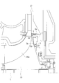
- FIG. 1 It is a longitudinal cross-sectional view of the exhaust gas turbocharger provided with the labyrinth seal part concerning one embodiment of the present invention.
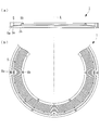
- the labyrinth seal part of FIG. 1 is shown, (a) is a longitudinal cross-sectional view of a labyrinth seal part, (b) is a top view of a labyrinth seal part.
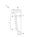
- FIG. 3 is a side cross-sectional view showing a state in which a cooling hole is connected to a labyrinth groove located on the outermost side in the radial direction centering on the axis in the labyrinth seal portion shown in FIG. 2; It is a principal part longitudinal cross-sectional view which showed the circumference
- FIG. 1 shows a longitudinal cross-sectional view of an exhaust turbine turbocharger (supercharger) 10 according to the present embodiment.
- the exhaust turbine turbocharger 10 is configured by integrally fastening the gas inlet casing 11, the gas outlet casing 12, the bearing stand 13, and the air guide casing 14 on the compressor side by bolts (not shown).
- the rotor shaft 15 is rotatably supported by the thrust bearing 16 and the radial bearings 17 and 18 in the bearing base 13, and a turbine (exhaust gas turbine) 19 constituting a turbine unit is consolidated at one end, and the other end
- the impeller 20 which comprises a compressor part is consolidated.
- the turbine 19 has a large number of blades 19 a at the outer peripheral portion.
- the blade 19 a is disposed between the exhaust gas introduction passage 22 provided in the gas inlet casing 11 and the exhaust gas discharge passage 23 provided in the gas outlet casing 12.
- the impeller 20 is disposed at the rear of the intake air introduction passage 24 provided in the air guide casing 14.
- the intake air introduction passage 24 is connected to the swirl chamber 25 via an impeller 20, and the swirl chamber 25 is further connected to a combustion chamber of the engine via an intake air introduction passage (not shown).
- Reference numeral 26 denotes a filter that rectifies the intake air by passing the intake air at a front stage sucked into the intake air introduction passage 24.
- a lubricating oil supply passage 27 is formed in the bearing stand 13, and a base end of the lubricating oil supply passage 27 is connected to an oil pump (not shown) of the engine.
- the other end of the lubricating oil supply passage 27 is branched into branch passages 28, 29 and 30 connected to the thrust bearing 16 and the radial bearings 17 and 18, respectively.
- a labyrinth seal portion 1 is provided at the end of the bearing stand 13 on the impeller 20 side to seal between the wall portion located on the back side of the impeller 20 and the back surface of the impeller 20.
- the labyrinth seal portion 1 is in sliding contact with the impeller 20 to prevent leakage of compressed air.
- the exhaust gas from the marine diesel engine passes through the exhaust gas introduction passage 22 and is generated by the axial exhaust gas flow that is static pressure expanded by the turbine nozzle.
- the turbine 19 is rotationally driven.
- the exhaust gas that has driven the turbine 19 is discharged from the exhaust gas discharge passage 23 to the outside.
- the rotation of the turbine 19 rotates the impeller 20 through the turbine rotor shaft 15, and the air taken in through the inlet air introduction passage 24 is pressurized by the impeller 20 and passes through the diffuser 33 and the outlet scroll 35. And supplied to marine diesel engines.
- the labyrinth seal part 1 is made into the ring shape which makes the axis line L a center axis line, for example, SS400 steel materials are used suitably.
- the labyrinth seal portion 1 is fixed to the casing main body 37 (see FIG. 1) by inserting bolts into the plurality of outer periphery bolt holes 8a and the plurality of inner periphery bolt holes 8b provided substantially parallel to the axis L. (A state in which the labyrinth seal portion 1 is fixed by bolts is shown in FIG. 4).
- the outer peripheral bolt holes 8 a and the inner peripheral bolt holes 8 b are provided at substantially equal intervals all around the labyrinth seal portion 1.
- a plurality of stages of labyrinth grooves 3 are formed on one end face of the labyrinth seal portion 1, that is, the end face facing the impeller 20.
- the labyrinth groove 3 is a plurality of circumferential grooves centered on the axis L.
- the groove dimensions (groove depth and groove width) of the respective labyrinth grooves 3 are approximately equal.
- annular space 7 through which a cooling medium flows is formed on the back surface (right side in FIG. 4) of the labyrinth seal portion 1.
- the cooling medium supplied from the main engine is taken into the annular space 7 from the bearing stand 13 of the side of the turbocharger.
- the annular space 7 has an annular shape with the axis L as a central axis, and is formed so as to open toward the back of the labyrinth seal portion 1.
- the annular space 7 has a substantially rectangular longitudinal cross section.
- the longitudinal dimension of the annular space 7, that is, the length in the direction orthogonal to the axis L (the longitudinal direction in FIG. 4) is long enough to cover a plurality of (four in the embodiment shown in FIG. 4) labyrinth grooves 3. It has become.
- the vertical dimension of the annular space 7 is appropriately set according to the required air amount.
- the labyrinth seal portion 1 is provided with a cooling hole 5 formed from the end face on the opposite side to the end face on which the labyrinth groove 3 is formed (hereinafter referred to as "front face") (end face on the right in FIG. 4) It is done.
- the cooling hole 5 extends substantially in parallel with the axis L, and connects the outermost circumferential groove 3a and the annular space 7 facing the back surface.
- the diameter of the cooling hole 5 is smaller than the diameter of the outermost peripheral groove 3a.
- a taper processing for expanding the diameter toward the annular space 7 is applied, and the air flow from the annular space 7 becomes smooth. It is done.
- the cooling holes 5 are provided at, for example, 24 places at substantially equal intervals all around the labyrinth seal portion 1.
- FIG. 5 is a graph showing the relationship between the cooling hole insertion position and the impeller metal temperature, with the horizontal axis representing the cooling air insertion position and the vertical axis representing the impeller metal temperature (relative comparison).
- the metal temperature at the outermost periphery of the impeller is the highest, then the metal temperature at an intermediate position (in the impeller 20, the middle between the outermost periphery and the innermost periphery), and finally the center
- the order of the metal temperatures in the vicinity is the same.
- the cooling air into the first stage (the cooling hole 5 connecting the outermost circumferential groove 3a and the annular space 7) is the highest in the cooling effect, and the second stage (the axial line L with respect to the outermost circumferential groove 3a) One cooling hole 5 located on the inner peripheral side, and finally the third step (cooling holes 5 located on the two inner peripheral sides of the outermost peripheral groove 3a with respect to the axis L). Further, it can be seen that the cooling effect is remarkably high when the cooling air is inserted into the first stage cooling hole 5 as compared with the case where the cooling air is inserted into the second and third stage cooling holes 5.
- the annular space 7 through which the cooling medium flows is provided on the back side of the labyrinth seal portion 1 and the cooling hole 5 is provided to connect the annular space 7 and the outermost peripheral groove 3a, seal air is circumferentially applied to the annular space 7 It is possible to make the flow uniform and thereafter supply the cooling air from the 24 cooling holes 5 of the labyrinth seal portion 1 to the outermost peripheral groove 3a. As a result, the number of the labyrinth grooves 3 need not be reduced, and the metal temperature of the impeller 20 raised to about 230 ° C. compared to the case where cooling is not performed while securing the sealability of the labyrinth seal portion 1 is approximately It can be lowered by 7 ° C.
- the cooling holes 5 are connected to the outermost peripheral groove 3 a in the plurality of labyrinth grooves 3.
- the present invention is not limited to this.
- the cooling hole 5 may be connected to the labyrinth groove 3 located on the inner peripheral side of one of the outermost peripheral groove 3a.
- the number of the holes of the labyrinth seal part 1 demonstrated as 24 places.
- the present invention is not limited to this, and is determined in consideration of the cooling effect, and may be an even place such as 12 places or 36 places or an odd place such as 21 places.
- the raw material of the labyrinth seal part 1 was demonstrated as SS400.
- this invention is not limited to this,
- steel materials such as SS490 or SS540, may be used.
- the cooling holes 5 are provided substantially parallel to the axis L.
- the present invention is not limited to this, as long as the cooling hole 5 just connects the labyrinth groove 3 and the annular space 7 and may be oblique with respect to the axis L, for example.
- the present invention is not limited to this, and for example, water vapor may be used.
- Labyrinth seal portion Labyrinth groove 3a Outermost peripheral groove (Labyrinth groove located at the outermost side in the radial direction centering on the axis) Reference Signs List 5 cooling hole 7 annular space 8a outer peripheral bolt hole 8b inner peripheral bolt hole 10 exhaust turbine turbocharger 11 gas inlet casing 12 gas outlet casing 13 bearing base 14 compressor side air guide casing 15 rotor shaft 16 thrust bearing 17, 18 radial bearing 19 Turbine 19a Blade 20 Impeller 22 Exhaust gas introduction passage 23 Exhaust gas discharge passage 24 Intake air introduction passage 25 Swirl chamber 26 Filter 27 Lubricating oil supply passage 28, 29, 30 Branch passage 31 Compressor housing 33 Diffuser 35 Exit scroll 37 Casing body L Axis
Abstract
Description
そこで、特許文献1には、ラビリンスシール部の中間部に空気通路を設け、冷却空気を供給することにより羽根車の温度上昇を防止する技術が開示されている。
また、特許文献2には、冷却媒体を羽根車外周側から流入する技術が開示されている。 In the conventional centrifugal compressor, the temperature of the air at the outlet of the impeller is high according to the pressure ratio of the centrifugal compressor, and for example, even when air at normal temperature is sucked, the pressure ratio is about 4.5. The temperature of the air at the car exit reaches 200 ° C. or more. When this high temperature air passes through the labyrinth seal that seals between the outlet of the impeller and the space formed in the back of the impeller, the frictional heat generated by the relative rotation between the labyrinth seal and the fins of the impeller The air is further heated, and the high heat causes the back of the impeller to be heated. Generally, in a single-stage centrifugal compressor that absorbs such air, an aluminum alloy is used as a material of the impeller. However, since the strength of the material rapidly decreases as the temperature of the aluminum alloy rises from 220 ° C. to 250 ° C. or more, it has been difficult to design and operate at a high pressure ratio.
Therefore,
In addition, Patent Document 2 discloses a technique in which a cooling medium flows in from the outer peripheral side of the impeller.
一方、特許文献2に開示されている技術では、羽根車温度が最も高くなる羽根車外周側に直接冷却媒体を導いていないため、冷却効果が低い。 However, even with the technology disclosed in
On the other hand, in the technology disclosed in Patent Document 2, the cooling effect is low because the cooling medium is not directly led to the impeller outer peripheral side where the impeller temperature is the highest.
すなわち、本発明の第1の態様にかかる遠心圧縮機は、軸線回りに回転する羽根車と、該羽根車の背面側に位置する壁部と該羽根車の背面との間をシールするラビリンスシール部と、を備えた遠心圧縮機において、前記ラビリンスシール部は、前記軸線を中心とする複数の円周溝とされたラビリンス溝を有し、複数の前記ラビリンス溝の少なくとも1つには、冷却媒体を流通させる冷却穴が接続されている。 In order to solve the above-mentioned subject, the centrifugal compressor of the present invention, the supercharger provided with this, and the operating method of a centrifugal compressor adopt the following means.
That is, in the centrifugal compressor according to the first aspect of the present invention, an impeller rotating around an axis, a labyrinth seal for sealing between a wall portion positioned on the back side of the impeller and the back of the impeller In the centrifugal compressor, the labyrinth seal section has a plurality of labyrinth grooves formed as a plurality of circumferential grooves centered on the axis, and at least one of the plurality of labyrinth grooves is cooled. There are connected cooling holes through which the medium flows.
また、ラビリンス溝に冷却穴を設け、冷却穴から羽根車へ冷却媒体を供給することにより、羽根車のメタル温度を低下させることができる。これにより、羽根車の温度が上昇して材料強度が低下することを回避することができる。 According to the first aspect of the present invention, the cooling holes for supplying the cooling medium to the impeller are connected to the labyrinth grooves, which are circumferential grooves. As described above, by using the labyrinth grooves also as a space for supplying the cooling medium, it is possible to cool the impeller without reducing the number of labyrinth grooves. Thereby, coexistence of cooling of an impeller and the sealability by a labyrinth seal part can be aimed at.
Further, the metal temperature of the impeller can be lowered by providing a cooling hole in the labyrinth groove and supplying the cooling medium from the cooling hole to the impeller. This can prevent the temperature of the impeller from rising and the material strength from decreasing.
また、冷却媒体を周方向に均一化する環状空間をラビリンスシール部の背面に配置し、かつ冷却穴を環状空間とラビリンス溝とを接続するように設けたので、特許文献1のようにラビリンス溝として使用できない空気通路を設ける必要がなく、冷却用としてラビリンス溝を直接利用することができる。これにより、ラビリンス溝の段数を減らす必要がないので、ラビリンスシール部によるシール性能を確保することができる。
さらに、冷却穴を離間した状態で複数形成したことにより、周方向の各所において効果的に羽根車を冷却できる。 According to the second aspect of the present invention, since the annular space through which the cooling medium flows is provided, the cooling medium can be made uniform in the circumferential direction.
Further, since the annular space for uniforming the cooling medium in the circumferential direction is disposed on the back of the labyrinth seal portion and the cooling hole is provided to connect the annular space and the labyrinth groove, as in
Furthermore, by forming a plurality of cooling holes in a separated state, it is possible to effectively cool the impeller at various places in the circumferential direction.
以下、本発明の一実施形態について、図1ないし図5を用いて説明する。
図1には、本実施形態に係る排気タービン過給機(過給機)10の縦断面図が示されている。排気タービン過給機10は、ガス入口ケーシング11、ガス出口ケーシング12、軸受台13、およびコンプレッサ側の空気案内ケーシング14がボルト(図示せず)によって一体に締結されることにより構成されている。ロータ軸15は、軸受台13内にスラスト軸受16およびラジアル軸受17,18により回転自在に支持されており、一端部にタービン部を構成するタービン(排気タービン)19が固結され、他端部にコンプレッサ部を構成する羽根車20が固結されている。 Hereinafter, embodiments according to the present invention will be described with reference to the drawings.
Hereinafter, an embodiment of the present invention will be described with reference to FIGS. 1 to 5.
FIG. 1 shows a longitudinal cross-sectional view of an exhaust turbine turbocharger (supercharger) 10 according to the present embodiment. The
一方、羽根車20は、空気案内ケーシング14に設けられた吸入空気導入路24の後方に配置されている。吸入空気導入路24は、羽根車20を介して渦巻き室25に接続され、さらに渦巻き室25は図示しない吸入空気導入路を介してエンジンの燃焼室に接続されている。
なお、符号26は吸入空気導入路24に吸入される前段で吸入空気を通過させることで吸入空気を整流するフィルタである。 The
On the other hand, the
タービン19の回転は、タービンロータ軸15を介して羽根車20を回転させ、入空気導入路24を通って吸入された空気は、羽根車20で加圧され、ディフューザ33および出口スクロール35を通って、舶用ディーゼル機関に供給される。 At the time of operation of the
The rotation of the
図2に示されているように、ラビリンスシール部1は、軸線Lを中心軸線とするリング形状とされており、例えばSS400鋼材が好適に用いられる。
ラビリンスシール部1は、軸線Lに略平行に設けられた複数の外周ボルト穴8a及び複数の内周ボルト穴8bのそれぞれにボルトを挿通させることにより、ケーシング本体37(図1参照)へ固定されている(なお、ボルトによりラビリンスシール部1が固定された状態は図4に示されている)。外周ボルト穴8a及び内周ボルト穴8bは、ラビリンスシール部1の全周に渡り略等間隔で設けられている。
図3に拡大して示されているように、ラビリンスシール部1の一方の端面、すなわち羽根車20に対向する端面には、複数段のラビリンス溝3が形成されている。ラビリンス溝3は、軸線Lを中心とする複数の円周溝とされている。ここで、各々のラビリンス溝3の溝寸法(溝深さ及び溝幅)は略等しく設けられている。 Next, the configuration of the
As FIG. 2 shows, the
The
As shown in an enlarged manner in FIG. 3, a plurality of stages of
冷却穴5は、図2(b)に示されているように、ラビリンスシール部1の全周に渡り略等間隔で例えば24箇所設けられている。 The
As shown in FIG. 2B, the cooling holes 5 are provided at, for example, 24 places at substantially equal intervals all around the
また、1段目(最外周溝3aと環状空間7を接続する冷却穴5)に冷却空気を挿入するのが最も冷却効果が高く、ついで2段目(軸線Lに対して最外周溝3aの一つ内周側に位置する冷却穴5)、最後に3段目(軸線Lに対して最外周溝3aの二つ内周側に位置する冷却穴5)の順になっている。
さらに、1段目の冷却穴5に冷却空気を挿入した場合は、2段目及び3段目の冷却穴5に冷却空気を挿入した場合に比べ、冷却効果が顕著に高いことがわかる。これは、2段目及び3段目から冷却空気を挿入すると、羽根車外周部から羽根車背面に入り込む空気が摩擦により高温となり、1段目から冷却空気を挿入する場合に比べて入熱量が多くなるためである。 FIG. 5 is a graph showing the relationship between the cooling hole insertion position and the impeller metal temperature, with the horizontal axis representing the cooling air insertion position and the vertical axis representing the impeller metal temperature (relative comparison). As shown in the figure, the metal temperature at the outermost periphery of the impeller is the highest, then the metal temperature at an intermediate position (in the
Further, inserting the cooling air into the first stage (the
Further, it can be seen that the cooling effect is remarkably high when the cooling air is inserted into the first
冷却媒体が流通する環状空間7をラビリンスシール部1の背面側に設けかつ冷却穴5を環状空間7と最外周溝3aとを接続するように設けたため、シール空気を環状空間7において周方向に流すことで均一化し、その後ラビリンスシール部1が有する24箇所の冷却穴5から最外周溝3aへ冷却空気を供給することができる。これにより、ラビリンス溝3の数を減らす必要がなくなり、ラビリンスシール部1のシール性を確保しつつ、冷却を行わない場合と比較して、約230℃まで上昇した羽根車20のメタル温度を約7℃低下させることができる。 According to the configuration described above, according to the present embodiment, the following effects can be obtained.
Since the
また、上述した各実施形態では、ラビリンスシール部1の穴の数が24箇所として説明した。しかし、本発明はこれに限定されるものではなく、冷却効果を考慮して決定され、例えば12箇所若しくは36箇所のような偶数箇所又は21箇所のような奇数箇所であっても良い。
また、上述した各実施形態では、ラビリンスシール部1の素材をSS400として説明した。しかし、本発明はこれに限定されるものではなく、例えばSS490又はSS540等の鋼材であっても良い。
また、冷却穴5は軸線Lと略平行に設けてあると説明した。しかし、本発明はこれに限定されるものではなく、冷却穴5はラビリンス溝3と環状空間7を接続してさえいればよく、例えば軸線Lに対して斜めであってもよい。
また、上述した各実施形態では、冷却媒体として空気を用いることとした。しかし、本発明はこれに限定されるものではなく、例えば水蒸気を用いてもよい。 In the above-described embodiment, it has been described that the cooling holes 5 are connected to the outermost
Moreover, in each embodiment mentioned above, the number of the holes of the
Moreover, in each embodiment mentioned above, the raw material of the
Further, it has been described that the cooling holes 5 are provided substantially parallel to the axis L. However, the present invention is not limited to this, as long as the
Moreover, in each embodiment mentioned above, we decided to use air as a cooling medium. However, the present invention is not limited to this, and for example, water vapor may be used.
3 ラビリンス溝
3a 最外周溝(軸線を中心とする半径方向最外側に位置するラビリンス溝)
5 冷却穴
7 環状空間
8a 外周ボルト穴
8b 内周ボルト穴
10 排気タービン過給機
11 ガス入口ケーシング
12 ガス出口ケーシング
13 軸受台
14 コンプレッサ側空気案内ケーシング
15 ロータ軸
16 スラスト軸受
17、18 ラジアル軸受
19 タービン
19a ブレード
20 羽根車
22 排気ガス導入路
23 排気ガス排出路
24 吸入空気導入路
25 渦巻き室
26 フィルタ
27 潤滑油供給通路
28、29、30 分岐通路
31 コンプレッサハウジング
33 ディフューザ
35 出口スクロール
37 ケーシング本体
L 軸線 1
Claims (6)
- 軸線回りに回転する羽根車と、
該羽根車の背面側に位置する壁部と該羽根車の背面との間をシールするラビリンスシール部と、
を備えた遠心圧縮機において、
前記ラビリンスシール部は、前記軸線を中心とする複数の円周溝とされたラビリンス溝を有し、
複数の前記ラビリンス溝の少なくとも1つには、冷却媒体を流通させる冷却穴が接続されていることを特徴とする遠心圧縮機。 An impeller rotating about an axis,
A labyrinth seal that seals between a wall located on the back side of the impeller and the back of the impeller;
In a centrifugal compressor equipped with
The labyrinth seal portion has labyrinth grooves formed as a plurality of circumferential grooves centered on the axis,
A centrifugal compressor characterized in that a cooling hole for circulating a cooling medium is connected to at least one of the plurality of labyrinth grooves. - 前記ラビリンスシール部の背面側には、前記冷却媒体が流通する環状空間が設けられ、
前記冷却穴は、前記環状空間と前記ラビリンス溝とを接続するように、それぞれが離間した状態で複数形成されていることを特徴とする請求項1に記載の遠心圧縮機。 An annular space through which the cooling medium flows is provided on the back side of the labyrinth seal portion,
The centrifugal compressor according to claim 1, wherein a plurality of the cooling holes are formed in a state of being separated from each other so as to connect the annular space and the labyrinth groove. - 前記冷却穴は、前記軸線を中心とする複数の前記ラビリンス溝のうち、最外周側のラビリンス溝に接続されていることを特徴とする請求項1または請求項2に記載の遠心圧縮機。 The centrifugal compressor according to claim 1 or 2, wherein the cooling hole is connected to a labyrinth groove on the outermost side among a plurality of the labyrinth grooves centered on the axis.
- 請求項1から3のいずれかに記載の遠心圧縮機と、
該遠心圧縮機を駆動する排気タービンと、
を備えていることを特徴とする過給機。 A centrifugal compressor according to any one of claims 1 to 3,
An exhaust turbine for driving the centrifugal compressor;
A supercharger characterized by having. - 排気タービンの回転により軸線回りに羽根車が回転する羽根車回転工程と、
前記羽根車の背面に位置するラビリンスシール部に設けられた前記軸線を中心とする複数の円周溝とされたラビリンス溝の少なくとも1つに冷却媒体を流通させる冷却媒体流通工程と、
を備えたことを特徴とする遠心圧縮機の運転方法。 An impeller rotation process in which an impeller rotates around an axis by rotation of an exhaust turbine;
A cooling medium circulating step of circulating a cooling medium through at least one of a plurality of circumferentially spaced labyrinth grooves centered on the axis line provided in a labyrinth seal portion located on the rear surface of the impeller;
A method of operating a centrifugal compressor comprising: - 前記冷却媒体流通工程は、複数の前記ラビリンス溝のうち、最外周側のラビリンス溝に前記冷却媒体を供給することを特徴とする請求項5に記載の遠心圧縮機の運転方法。 The method of operating a centrifugal compressor according to claim 5, wherein in the cooling medium circulating step, the cooling medium is supplied to a labyrinth groove on the outermost side among the plurality of labyrinth grooves.
Priority Applications (3)
| Application Number | Priority Date | Filing Date | Title |
|---|---|---|---|
| CN201380063139.4A CN104903586A (en) | 2012-12-05 | 2013-12-02 | Centrifugal compressor, supercharger with same, and method for operating centrifugal compressor |
| KR1020157014736A KR20150081342A (en) | 2012-12-05 | 2013-12-02 | Centrifugal compressor, supercharger with same, and method for operating centrifugal compressor |
| EP13861290.8A EP2930370A4 (en) | 2012-12-05 | 2013-12-02 | Centrifugal compressor, supercharger with same, and method for operating centrifugal compressor |
Applications Claiming Priority (2)
| Application Number | Priority Date | Filing Date | Title |
|---|---|---|---|
| JP2012266274A JP2014111905A (en) | 2012-12-05 | 2012-12-05 | Centrifugal compressor and supercharger with the same, and operation method for centrifugal compressor |
| JP2012-266274 | 2012-12-05 |
Publications (1)
| Publication Number | Publication Date |
|---|---|
| WO2014087966A1 true WO2014087966A1 (en) | 2014-06-12 |
Family
ID=50883383
Family Applications (1)
| Application Number | Title | Priority Date | Filing Date |
|---|---|---|---|
| PCT/JP2013/082346 WO2014087966A1 (en) | 2012-12-05 | 2013-12-02 | Centrifugal compressor, supercharger with same, and method for operating centrifugal compressor |
Country Status (5)
| Country | Link |
|---|---|
| EP (1) | EP2930370A4 (en) |
| JP (1) | JP2014111905A (en) |
| KR (1) | KR20150081342A (en) |
| CN (1) | CN104903586A (en) |
| WO (1) | WO2014087966A1 (en) |
Cited By (1)
| Publication number | Priority date | Publication date | Assignee | Title |
|---|---|---|---|---|
| WO2016102137A1 (en) * | 2014-12-23 | 2016-06-30 | Robert Bosch Gmbh | Turbomachine |
Families Citing this family (7)
| Publication number | Priority date | Publication date | Assignee | Title |
|---|---|---|---|---|
| JP6404087B2 (en) * | 2014-11-05 | 2018-10-10 | 三菱重工業株式会社 | Centrifugal compressor and supercharger provided with the same |
| JP6147777B2 (en) * | 2015-01-26 | 2017-06-14 | 三菱重工業株式会社 | Intake rectifier, compressor provided with the same |
| JP6382120B2 (en) * | 2015-01-26 | 2018-08-29 | 三菱重工業株式会社 | Exhaust turbine turbocharger |
| JP6246847B2 (en) | 2016-02-22 | 2017-12-13 | 三菱重工業株式会社 | Impeller back cooling structure and turbocharger |
| CN110671157A (en) * | 2019-11-22 | 2020-01-10 | 东方电气集团东方汽轮机有限公司 | Radial steam seal structure for radial turbine and radial turbine |
| JP7105823B2 (en) * | 2020-02-28 | 2022-07-25 | 三菱重工マリンマシナリ株式会社 | supercharger |
| KR20230131946A (en) | 2021-04-01 | 2023-09-14 | 미쓰비시주코마린마시나리 가부시키가이샤 | supercharger |
Citations (4)
| Publication number | Priority date | Publication date | Assignee | Title |
|---|---|---|---|---|
| JP2934530B2 (en) | 1991-06-14 | 1999-08-16 | 三菱重工業株式会社 | Centrifugal compressor |
| JP2008045425A (en) * | 2006-08-11 | 2008-02-28 | Mitsubishi Heavy Ind Ltd | Centrifugal compressor |
| JP2010506091A (en) * | 2006-10-12 | 2010-02-25 | エムアーエヌ・ディーゼル・エスエー | Compressor for turbocharger and cooling method thereof |
| JP4503726B2 (en) | 1998-05-25 | 2010-07-14 | エービービー シュヴァイツ アクチェンゲゼルシャフト | Centrifugal compressor |
Family Cites Families (1)
| Publication number | Priority date | Publication date | Assignee | Title |
|---|---|---|---|---|
| EP2067999A1 (en) * | 2007-12-06 | 2009-06-10 | Napier Turbochargers Limited | Liquid cooled turbocharger impeller and method for cooling an impeller |
-
2012
- 2012-12-05 JP JP2012266274A patent/JP2014111905A/en active Pending
-
2013
- 2013-12-02 WO PCT/JP2013/082346 patent/WO2014087966A1/en active Application Filing
- 2013-12-02 EP EP13861290.8A patent/EP2930370A4/en not_active Withdrawn
- 2013-12-02 KR KR1020157014736A patent/KR20150081342A/en active Search and Examination
- 2013-12-02 CN CN201380063139.4A patent/CN104903586A/en active Pending
Patent Citations (4)
| Publication number | Priority date | Publication date | Assignee | Title |
|---|---|---|---|---|
| JP2934530B2 (en) | 1991-06-14 | 1999-08-16 | 三菱重工業株式会社 | Centrifugal compressor |
| JP4503726B2 (en) | 1998-05-25 | 2010-07-14 | エービービー シュヴァイツ アクチェンゲゼルシャフト | Centrifugal compressor |
| JP2008045425A (en) * | 2006-08-11 | 2008-02-28 | Mitsubishi Heavy Ind Ltd | Centrifugal compressor |
| JP2010506091A (en) * | 2006-10-12 | 2010-02-25 | エムアーエヌ・ディーゼル・エスエー | Compressor for turbocharger and cooling method thereof |
Non-Patent Citations (1)
| Title |
|---|
| See also references of EP2930370A4 * |
Cited By (2)
| Publication number | Priority date | Publication date | Assignee | Title |
|---|---|---|---|---|
| WO2016102137A1 (en) * | 2014-12-23 | 2016-06-30 | Robert Bosch Gmbh | Turbomachine |
| US10598014B2 (en) | 2014-12-23 | 2020-03-24 | Robert Bosch Gmbh | Turbomachine |
Also Published As
| Publication number | Publication date |
|---|---|
| EP2930370A4 (en) | 2015-12-02 |
| JP2014111905A (en) | 2014-06-19 |
| CN104903586A (en) | 2015-09-09 |
| EP2930370A1 (en) | 2015-10-14 |
| KR20150081342A (en) | 2015-07-13 |
Similar Documents
| Publication | Publication Date | Title |
|---|---|---|
| WO2014087966A1 (en) | Centrifugal compressor, supercharger with same, and method for operating centrifugal compressor | |
| US10526907B2 (en) | Internally cooled seal runner | |
| US8262342B2 (en) | Gas turbine engine assemblies with recirculated hot gas ingestion | |
| US8727715B2 (en) | Turbomachine | |
| US8191374B2 (en) | Two-shaft gas turbine | |
| EP2252798B1 (en) | Impeller and turbocharger | |
| US7682131B2 (en) | Impeller baffle with air cavity deswirlers | |
| EP1926915B1 (en) | Stationary seal ring for a centrifugal compressor | |
| JP6441611B2 (en) | Gas turbine exhaust member and exhaust chamber maintenance method | |
| JP5125684B2 (en) | Turbocharger | |
| JP5135981B2 (en) | Centrifugal compressor | |
| JP2000054997A (en) | Centrifugal compressor | |
| JP2006510855A (en) | Compliant support for axial thrust bearings with increased load capacity | |
| KR101704986B1 (en) | Labyrinth seal device for axial-flow turbine and exhaust gas turbocharger equipped with same | |
| CN107849973B (en) | Impeller back surface cooling structure and supercharger | |
| WO2017168626A1 (en) | Turbocharger | |
| KR101382309B1 (en) | Bearing of turbo-charger | |
| JP5230590B2 (en) | Exhaust inlet casing of exhaust turbine supercharger | |
| WO2016067715A1 (en) | Supercharger and engine with same | |
| US10815829B2 (en) | Turbine housing assembly | |
| JP2005163641A (en) | Turbocharger | |
| US11339663B2 (en) | Rotor having improved structure, and turbine and gas turbine including the same | |
| WO2022208839A1 (en) | Supercharger | |
| JP2007321654A (en) | Supercharger | |
| JP2005194914A (en) | Sealing structure and turbine nozzle |
Legal Events
| Date | Code | Title | Description |
|---|---|---|---|
| 121 | Ep: the epo has been informed by wipo that ep was designated in this application |
Ref document number: 13861290 Country of ref document: EP Kind code of ref document: A1 |
|
| REEP | Request for entry into the european phase |
Ref document number: 2013861290 Country of ref document: EP |
|
| WWE | Wipo information: entry into national phase |
Ref document number: 2013861290 Country of ref document: EP |
|
| ENP | Entry into the national phase |
Ref document number: 20157014736 Country of ref document: KR Kind code of ref document: A |
|
| NENP | Non-entry into the national phase |
Ref country code: DE |