JP4503726B2 - Centrifugal compressor - Google Patents
Centrifugal compressor Download PDFInfo
- Publication number
- JP4503726B2 JP4503726B2 JP14544299A JP14544299A JP4503726B2 JP 4503726 B2 JP4503726 B2 JP 4503726B2 JP 14544299 A JP14544299 A JP 14544299A JP 14544299 A JP14544299 A JP 14544299A JP 4503726 B2 JP4503726 B2 JP 4503726B2
- Authority
- JP
- Japan
- Prior art keywords
- compressor
- gap
- separation gap
- compressor impeller
- casing
- Prior art date
- Legal status (The legal status is an assumption and is not a legal conclusion. Google has not performed a legal analysis and makes no representation as to the accuracy of the status listed.)
- Expired - Lifetime
Links
Images


Classifications
-
- F—MECHANICAL ENGINEERING; LIGHTING; HEATING; WEAPONS; BLASTING
- F04—POSITIVE - DISPLACEMENT MACHINES FOR LIQUIDS; PUMPS FOR LIQUIDS OR ELASTIC FLUIDS
- F04D—NON-POSITIVE-DISPLACEMENT PUMPS
- F04D17/00—Radial-flow pumps, e.g. centrifugal pumps; Helico-centrifugal pumps
- F04D17/08—Centrifugal pumps
-
- F—MECHANICAL ENGINEERING; LIGHTING; HEATING; WEAPONS; BLASTING
- F04—POSITIVE - DISPLACEMENT MACHINES FOR LIQUIDS; PUMPS FOR LIQUIDS OR ELASTIC FLUIDS
- F04D—NON-POSITIVE-DISPLACEMENT PUMPS
- F04D29/00—Details, component parts, or accessories
- F04D29/08—Sealings
- F04D29/16—Sealings between pressure and suction sides
- F04D29/161—Sealings between pressure and suction sides especially adapted for elastic fluid pumps
- F04D29/162—Sealings between pressure and suction sides especially adapted for elastic fluid pumps of a centrifugal flow wheel
-
- F—MECHANICAL ENGINEERING; LIGHTING; HEATING; WEAPONS; BLASTING
- F04—POSITIVE - DISPLACEMENT MACHINES FOR LIQUIDS; PUMPS FOR LIQUIDS OR ELASTIC FLUIDS
- F04D—NON-POSITIVE-DISPLACEMENT PUMPS
- F04D29/00—Details, component parts, or accessories
- F04D29/58—Cooling; Heating; Diminishing heat transfer
- F04D29/582—Cooling; Heating; Diminishing heat transfer specially adapted for elastic fluid pumps
- F04D29/5846—Cooling; Heating; Diminishing heat transfer specially adapted for elastic fluid pumps cooling by injection
Description
【0001】
【発明の属する技術分野】
本発明は、遠心圧縮機であって、シャフトに配置されてほぼ半径方向に延びる背壁を備えた圧縮機インペラ、圧縮機インペラを取り囲む圧縮機ケーシング、遠心圧縮機の作業媒体のための、圧縮機インペラと圧縮機ケーシングとの間に形成された流路、圧縮機インペラと圧縮機ケーシングとの間の、流路に接続された分離間隙、ガス状の冷却媒体のための、圧縮機ケーシング内に配置された送り装置、及びガス状の冷却媒体のための、圧縮機ケーシング内に配置された排出装置を有しており、送り装置が分離間隙内に開口しており、分離間隙が圧縮機インペラの背壁の領域にほぼ半径方向に延びる間隙区分を有している形式のものに関する。
【0002】
【従来の技術】
回転機構(rotierendes System)の密閉のために、ターボ機械構造において無接触のシール、特にラビリンスシールが幅広く形成されている。回転部分と定置部分との間の媒体の流過する分離間隙内には流動境界層(Stroemungsgrenzschicht)の形成に基づき高い摩擦損失が生じる。これによって、分離間隙内の流体の加熱が生じて、ひいては分離間隙を取り囲む構成部分の加熱も生じる。高い材料温度は、対応する構成部分の耐用年数を減少させてしまうことになる。
【0003】
ヨーロッパ特許0518027B1号公報により、圧縮機インペラの背壁で圧縮機ケーシングと圧縮機インペラとの間の分離間隙内に配置されたラビリンスシールを備える遠心圧縮機が公知である。圧縮機インペラの出口における高い圧力に基づき圧縮機ケーシングの定置の壁と回転する壁との間のリング室内に漏れ空気が入り込む。分離間隙を取り囲む構成部分の加熱を避けるために、圧縮機インペラの出口の圧力よりも高い圧力の冷たいガスが分離間隙内に導入される。このためにラビリンスシール内に付加的なリング室が配置されて、外部のガス供給部に接続されている。冷たいガスが圧縮機ケーシングの壁を通ってラビリンスシール内に流入し、かつまず圧縮機インペラの背壁に衝突して、該背壁を冷却する。背壁への衝突に際して、ガスは分割されて、主として半径方向で内側及び外側へラビリンスシールの個別のシールエレメントを通って流れる。特に半径方向外側へ向けられた部分流が、圧縮機インペラの出口からの熱い圧縮機空気の、分離間隙の流過を阻止しようとするものである。
【0004】
遠心圧縮機を高価なものにする特別な付加構造にも拘わらず、前記手段の冷却作用は最適ではない。冷たいガスの供給に際して、半径方向外側に向けられた部分流がまず、圧縮機インペラの背壁に形成された境界層と混合する。さらに、該部分流は無接触のシールの少なくとも1つのシールエレメントに抗して作用しなければならず、低い冷却作用のほかに、背壁における高い摩擦、並びに機械的な高い損失が生じる。
【0005】
【発明が解決しようとする課題】
本発明の課題は、前述のすべての欠点を避けて、簡単な、しかしながら効率の改善された冷却装置を備えた遠心圧縮機を提供することである。
【0006】
【課題を解決するための手段】
前記課題を解決するために本発明の構成では、冒頭に述べた形式の遠心圧縮機において、ガス状の冷却媒体のための送り装置が、圧縮機インペラのほぼ半径方向に延びる背壁よりも半径方向外側で分離間隙に開口している。
【0007】
【発明の効果】
本発明に基づく前記構成により、分離間隙のほぼ半径方向に延びる間隙区分における付加的なリング室若しくは付加的な供給室が省略できる。さらに、使用される冷却媒体が、分離間隙のほぼ半径方向に延びる間隙区分に入り込むことになる熱い漏れ空気を代替する。これによって、圧縮機インペラの背壁に沿って生じる流動境界層が始めから特に、供給された冷却媒体によって形成される。従って、遠心圧縮機の特に危険な領域で改善された冷却作用が保証される。
【0008】
特に有利には、送り装置の供給通路と分離間隙のほぼ半径方向に延びる間隙区分の入口部分とが半径方向で互いに合致するように配置されている。これによって、流入する冷却媒体の圧力損失並びに散逸に起因する冷却媒体の加熱が避けられる。その結果、改善された冷却作用が得られる。さらに、冷却媒体はほぼ半径方向に延びる間隙区分内への熱い漏れ空気の入り込みをさえぎる。
【0009】
さらに有利には供給通路が、冷却媒体のための、圧縮機インペラの回転方向に向けられた複数の送り通路から成っている。このために、供給通路が、切欠きによって中断された複数の案内ウエブを有しており、切欠きが冷却媒体のための送り通路を形成している。これによって、比較的簡単な構成部分を用いて圧縮機インペラの回転方向での冷却媒体の送り込みが行われ、その結果、摩擦損失、ひいては圧縮機インペラの加熱が著しく減少される。
【0010】
さらに有利には、ほぼ半径方向に延びる間隙区分の入口部分の上流側で分離間隙内にシールエレメントが配置されている。これによって、圧縮機インペラから到来する漏れ流内の圧力をさらに減少させることができ、その結果、冷却媒体が圧縮機インペラ出口に作用する圧力よりも低い圧力で供給され得る。
【0011】
特に有利には、入口部分の下流側で、分離間隙のほぼ半径方向に延びる間隙区分内に無接触のシールが配置されている。この場合、半径方向外側から到来する冷却媒体がシールの個別のシールエレメント内に到達して、そこで圧縮機インペラの背壁にフィルム冷却(Filmkuehlung: film cooling)を生ぜしめる。公知技術とは異なって本発明では、冷却媒体が半径方向外側へではなく、半径方向内側へ流れ、従って圧縮機インペラの背壁に形成される流動境界層の混合を生ぜしめることなく、かつ背壁に対する摩擦を増大させることもない。結果として、冷却効果が高められ、圧縮機インペラの耐用年数が著しく改善される。
【0012】
【発明の実施の形態】
発明の理解にとって重要な構成部分のみを図示してあり、例えば支承部分及び、排ガスターボ過給機のタービン側は図示してない。作業媒体(Arbeitsmittel)の流れは矢印で示してある。
【0013】
図1に部分的に示す排ガスターボ過給機は、遠心圧縮機(Radialverdichter: centrifugal compressor)1及び排ガスタービン(図示せず)から成っており、遠心圧縮機と排ガスタービンとはシャフト3を介して互いに結合されており、シャフトは支承ケーシング(Lagergehaeuse)2内に保持されている。遠心圧縮機1は、シャフト3内に位置する機械軸線4を有している。遠心圧縮機は圧縮機ケーシング5を備えており、圧縮機ケーシング内で圧縮機インペラ(Verdichterrad: compressor impeller)6が回転可能にシャフト3に結合されている。圧縮機インペラ6は、複数の動翼7及び、該動翼を保持するハブ8から成っている。ハブ8と圧縮機ケーシング5との間に流路9が形成されている。動翼7の下流側で流路9に、半径方向に配置されて羽根の付けられたディフューザ10を接続してあり、ディフューザが遠心圧縮機1の渦形室(Spirale: volute)11に開口している。圧縮機ケーシング(Verdichtergehaeuse)5は主として、空気入口ケーシング(Lufteintrittgehaeuse)12、空気出口ケーシング(Luftaustrittgehaeuse)13、ディフューザプレート(Diffusorplatte)14及び、支承ケーシング2に対する中間壁15から形成されている。
【0014】
ハブ8はタービン側に背壁16並びに、シャフト3のための取り付けスリーブ17を有しており、この場合、シャフトと取り付けスリーブ17とが互いに結合されている。取り付けスリーブ17は圧縮機ケーシング5の中間壁15によって受容されている。もちろん、適当な別の圧縮機インペラ・シャフト結合が選ばれてよい。羽根の付けられていないディフューザの使用も可能である。
【0015】
回転する圧縮機インペラ6と圧縮機ケーシング5の定置の中間壁15との間に、異なる区分から成る分離間隙(Trennspalt)18が形成されている。分離間隙の第1の間隙区分(Spaltbereich)19が機械軸線4に対して平行に延びていて、圧縮機インペラ6の出口並びに、圧縮機インペラ6の背壁16の領域(Bereich: region)でほぼ半径方向に延びる第2の間隙区分20に接続されている。第2の間隙区分は、取り付けスリーブ17と中間壁15との間に形成されて同じく機械軸線4に対して平行に延びる第3の間隙区分21内へ移行している。ほぼ半径方向に延びる第2の間隙区分20の構成部分として、第1の間隙区分19に続く入口部分(Eintrittbereich)22、ラビリンスシール(Labyrinthdichtung)として形成された無接触(beruehrungsfrei)のシール23及び、第3の間隙区分21に接続された中間室24がある。中間室は排出管路(図示せず)に連通している。
【0016】
第2の間隙区分20の上流側で、供給通路(Versorgungskanal)25及び送り管路(Zufuehrleitung)26から成る送り装置(Zufuehreinrichtung)27が、分離間隙18に開口している。このために、ディフューザプレート14が中央の区分に送り管路26の受容のための開口部28を備えていて、かつ半径方向内側の端部に、供給通路25として形成されたスリットを有している。供給通路25は分離間隙18の第2の間隙区分20の入口部分22と合致するように配置されている。
【0017】
排ガスターボ過給機の運転に際して、圧縮機インペラ6が作業媒体29として周囲空気を吸い込み、該周囲空気が流路9並びにディフューザ10を通って渦形室11内に達して、そこで圧縮されて、最終的に、排ガスターボ過給機に接続された内燃機関の過給のために投入される。遠心圧縮機1内で加熱される周囲空気(作業媒体)29は流路9からディフューザ10への通過中に漏れ流30として第1の間隙区分19、ひいては分離間隙18をも負荷する。同時に、送り装置27を介してガス状の冷却媒体31が分離間隙18の第2の間隙区分内に導入される。冷却媒体は例えば内燃機関の過給空気冷却器の出口(図示せず)からの空気であってよい。もちろん、別の冷却媒体の使用並びに冷却媒体の外部からの供給も可能である。
【0018】
冷却媒体31が熱い漏れ流30を代替し、従って、圧縮機インペラ6の背壁16に沿った境界層(Grenzschicht)が、既に始めから主として、供給された冷却媒体31によって形成される。冷却媒体31はもっぱら半径方向内側へ流れるので、著しく改善された冷却作用が得られ、かつ摩擦損失も減少される。、冷却媒体31は作業媒体29の漏れ流30と一緒に分離間隙18から、中間室24及び、圧縮機ケーシング5の中間壁15内に形成された排出通路32(詳細には図示せず)を介して導出される。
【0019】
第2の実施例においては、ディフューザプレート14が供給通路25の領域に中間リング33を備えており、中間リングが送り管路26を受容している(図2)。中間リング33は周囲にわたって分配された複数の案内ウエブ34を有しており、案内ウエブが供給溝35として形成された切欠きによって中断されている(図3)。この場合に案内ウエブ34は、供給溝35が圧縮機インペラ6の回転方向に向くように形成されている。これによって、冷却媒体31のいわゆる旋回・送り込み(Mitdrall-Einblasung: positively swirled injedtion)が行われ、摩擦損失、ひいては圧縮機インペラ6の加熱が著しく減少される。もちろんこのような効果は、ディフューザ14を供給通路25の領域で相応に成形する(図示せず)ことによって達成されてよい。
【0020】
第3の実施例においては、第2の間隙区分20の入口部分22の上流側で分離間隙18内にシールエレメント36が配置されている(図4)。シールエレメント36を用いて、残留する漏れ流の圧力を、流入する冷却媒体31の圧力が有利に、それも作業媒体29の、圧縮機インペラ6の出口に作用する圧力よりも低くなるように、著しく減少させることが可能である。これによって、冷却媒体31の比較的わずかな量で、圧縮機インペラ6の効果的な冷却が保証される。
【図面の簡単な説明】
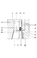
【図1】本発明に基づく送り装置を備えた遠心圧縮機の部分縦断面図
【図2】別の実施例のディフューザプレートの部分の断面図
【図3】図2の線III−IIIに沿った部分横断面図
【図4】さらに別の実施例の分離間隙の部分の拡大断面図
【符号の説明】
1 遠心圧縮機、 2 支承ケーシング、 3 シャフト、 4 機械軸線、 5 圧縮機ケーシング、 6 圧縮機インペラ、 7 動翼、 8 ハブ、 9 流路、 10 ディフューザ、 11 渦形室、 12 空気入口ケーシング、 13 空気出口ケーシング、 14 ディフューザプレート、 15 中間壁、 16 背壁、 17 取り付けスリーブ、 18 分離間隙、 19,20,21 間隙区分、 22 入口部分、 23 シール、 24 中間室、 25 供給通路、 26 送り管路、 27 送り装置、 28 開口部、 29 作業媒体、 30 漏れ流、 31 冷却媒体、 32 排出通路、 33 中間リング、 34 案内ウエブ、 35 供給通路、 36 シールエレメント[0001]
BACKGROUND OF THE INVENTION
The present invention is a centrifugal compressor, a compressor impeller disposed on a shaft and having a substantially radially extending back wall, a compressor casing surrounding the compressor impeller, a compression for a working medium of the centrifugal compressor A flow path formed between the compressor impeller and the compressor casing, a separation gap connected to the flow path between the compressor impeller and the compressor casing, in the compressor casing for the gaseous cooling medium And a discharge device arranged in the compressor casing for the gaseous cooling medium , the feed device opening into the separation gap, the separation gap being a compressor It is of the type having a gap section extending substantially radially in the region of the back wall of the impeller.
[0002]
[Prior art]
Due to the sealing of the rotation mechanism (rotierendes system), non-contact seals, in particular labyrinth seals, are widely formed in turbomachine structures. In the separation gap where the medium flows between the rotating part and the stationary part, a high friction loss occurs due to the formation of a fluid boundary layer (Stroemungsgrenzschicht). This causes heating of the fluid in the separation gap and thus heating of the components surrounding the separation gap. High material temperatures will reduce the service life of the corresponding components.
[0003]
From European Patent No. 0518027B1, a centrifugal compressor is known which comprises a labyrinth seal arranged in the separation gap between the compressor casing and the compressor impeller on the back wall of the compressor impeller. Leakage air enters the ring chamber between the stationary wall of the compressor casing and the rotating wall due to the high pressure at the outlet of the compressor impeller. In order to avoid heating the components surrounding the separation gap, cold gas with a pressure higher than the pressure at the outlet of the compressor impeller is introduced into the separation gap. For this purpose, an additional ring chamber is arranged in the labyrinth seal and is connected to an external gas supply. Cold gas flows through the wall of the compressor casing into the labyrinth seal and first strikes the back wall of the compressor impeller to cool the back wall. Upon impact on the back wall, the gas is split and flows through the individual sealing elements of the labyrinth seal, mainly radially inward and outward. In particular, the partial flow directed radially outward is intended to prevent the flow of hot compressor air from the outlet of the compressor impeller through the separation gap.
[0004]
Despite the special additional structure that makes the centrifugal compressor expensive, the cooling action of the means is not optimal. When supplying the cold gas, the partial flow directed radially outward first mixes with the boundary layer formed on the back wall of the compressor impeller. Furthermore, the partial flow must act against at least one sealing element of a contactless seal, resulting in high friction on the back wall as well as high mechanical loss in addition to low cooling action.
[0005]
[Problems to be solved by the invention]
The object of the present invention is to provide a centrifugal compressor with a cooling device which is simple, but with improved efficiency, avoiding all the aforementioned drawbacks.
[0006]
[Means for Solving the Problems]
In order to solve the above-mentioned problems, in the configuration of the present invention, in the centrifugal compressor of the type described at the beginning, the feeding device for the gaseous cooling medium has a radius that is greater than the back wall of the compressor impeller extending in the substantially radial direction. The separation gap is opened on the outside in the direction.
[0007]
【The invention's effect】
With the arrangement according to the invention, additional ring chambers or additional supply chambers in the gap section extending in the substantially radial direction of the separation gap can be dispensed with. Furthermore, the cooling medium used replaces hot leaked air that will enter the substantially radially extending gap section of the separation gap. Thereby, a fluid boundary layer that forms along the back wall of the compressor impeller is formed, in particular, by the supplied cooling medium. An improved cooling action is thus ensured in a particularly dangerous area of the centrifugal compressor.
[0008]
Particularly preferably, the feed passage of the feeder and the inlet portion of the gap section extending in the substantially radial direction of the separation gap are arranged so as to coincide with each other in the radial direction. This avoids heating of the cooling medium due to pressure loss and dissipation of the incoming cooling medium. As a result, an improved cooling effect is obtained. Furthermore, the cooling medium blocks the entry of hot leak air into the gap section extending in a substantially radial direction.
[0009]
More preferably, the supply passage comprises a plurality of feed passages for the cooling medium directed in the direction of rotation of the compressor impeller. For this purpose, the supply passage has a plurality of guide webs interrupted by the notches, the notches forming a feed passage for the cooling medium. As a result, the cooling medium is fed in the direction of rotation of the compressor impeller using relatively simple components, with the result that friction losses and thus heating of the compressor impeller are significantly reduced.
[0010]
More advantageously, a sealing element is arranged in the separation gap upstream of the inlet portion of the substantially radially extending gap section. This can further reduce the pressure in the leakage flow coming from the compressor impeller, so that the cooling medium can be supplied at a pressure lower than the pressure acting on the compressor impeller outlet.
[0011]
Particularly advantageously, a contactless seal is arranged downstream of the inlet portion and in a gap section extending substantially radially of the separation gap. In this case, the cooling medium coming from the radially outer side reaches into the individual sealing elements of the seal, where it causes film cooling (Filmkuehlung: film cooling) on the back wall of the compressor impeller. Unlike the prior art, in the present invention, the cooling medium flows radially inward rather than radially outward, thus causing no mixing of the fluid boundary layer formed on the back wall of the compressor impeller and the backside. It does not increase the friction against the walls. As a result, the cooling effect is enhanced and the service life of the compressor impeller is significantly improved.
[0012]
DETAILED DESCRIPTION OF THE INVENTION
Only the components which are important for the understanding of the invention are shown, for example the bearing part and the turbine side of the exhaust gas turbocharger are not shown. The flow of the working medium (Arbeitsmittel) is indicated by arrows.
[0013]
The exhaust gas turbocharger partially shown in FIG. 1 includes a centrifugal compressor (Radialverdichter: centrifugal compressor) 1 and an exhaust gas turbine (not shown). The centrifugal compressor and the exhaust gas turbine are connected via a
[0014]
The
[0015]
Between the rotating compressor impeller 6 and the stationary
[0016]
A feeding device (Zufuehreinrichtung) 27 consisting of a supply passage (Versorgungskanal) 25 and a feeding line (Zufuehrleitung) 26 opens in the
[0017]
During the operation of the exhaust gas turbocharger, the compressor impeller 6 sucks ambient air as the working
[0018]
The cooling
[0019]
In the second embodiment, the
[0020]
In the third embodiment, a sealing
[Brief description of the drawings]
FIG. 1 is a partial longitudinal sectional view of a centrifugal compressor provided with a feeding device according to the present invention. FIG. 2 is a sectional view of a portion of another embodiment of a diffuser plate. FIG. 3 is taken along line III-III in FIG. Partial cross-sectional view [FIG. 4] Enlarged cross-sectional view of a separation gap portion of still another embodiment [Explanation of symbols]
DESCRIPTION OF
Claims (6)
Applications Claiming Priority (2)
| Application Number | Priority Date | Filing Date | Title |
|---|---|---|---|
| EP98810487A EP0961034B1 (en) | 1998-05-25 | 1998-05-25 | Radial compressor |
| EP98810487.3 | 1998-05-25 |
Publications (2)
| Publication Number | Publication Date |
|---|---|
| JP2000054997A JP2000054997A (en) | 2000-02-22 |
| JP4503726B2 true JP4503726B2 (en) | 2010-07-14 |
Family
ID=8236108
Family Applications (1)
| Application Number | Title | Priority Date | Filing Date |
|---|---|---|---|
| JP14544299A Expired - Lifetime JP4503726B2 (en) | 1998-05-25 | 1999-05-25 | Centrifugal compressor |
Country Status (8)
| Country | Link |
|---|---|
| US (1) | US6238179B1 (en) |
| EP (1) | EP0961034B1 (en) |
| JP (1) | JP4503726B2 (en) |
| KR (1) | KR100537036B1 (en) |
| CN (2) | CN2381815Y (en) |
| CZ (1) | CZ291692B6 (en) |
| DE (1) | DE59809488D1 (en) |
| TW (1) | TW562900B (en) |
Cited By (1)
| Publication number | Priority date | Publication date | Assignee | Title |
|---|---|---|---|---|
| WO2014087966A1 (en) | 2012-12-05 | 2014-06-12 | 三菱重工業株式会社 | Centrifugal compressor, supercharger with same, and method for operating centrifugal compressor |
Families Citing this family (25)
| Publication number | Priority date | Publication date | Assignee | Title |
|---|---|---|---|---|
| DE10325980A1 (en) * | 2003-06-07 | 2004-12-23 | Daimlerchrysler Ag | Exhaust gas turbocharger for internal combustion engine has at least one nozzle for subjecting wheel back to cooling fluid arranged close to rotation axis of compressor wheel |
| US7252474B2 (en) * | 2003-09-12 | 2007-08-07 | Mes International, Inc. | Sealing arrangement in a compressor |
| US7234918B2 (en) * | 2004-12-16 | 2007-06-26 | Siemens Power Generation, Inc. | Gap control system for turbine engines |
| DE102005018771B4 (en) * | 2005-04-22 | 2015-06-18 | Man Diesel & Turbo Se | Internal combustion engine |
| DE602006015076D1 (en) * | 2005-09-19 | 2010-08-05 | Ingersoll Rand Co | |
| US20070065276A1 (en) * | 2005-09-19 | 2007-03-22 | Ingersoll-Rand Company | Impeller for a centrifugal compressor |
| US20070063449A1 (en) * | 2005-09-19 | 2007-03-22 | Ingersoll-Rand Company | Stationary seal ring for a centrifugal compressor |
| US8556516B2 (en) * | 2010-08-26 | 2013-10-15 | Hamilton Sundstrand Corporation | Compressor bearing cooling inlet plate |
| JP5700999B2 (en) * | 2010-10-06 | 2015-04-15 | 三菱重工業株式会社 | Centrifugal compressor |
| US8784048B2 (en) * | 2010-12-21 | 2014-07-22 | Hamilton Sundstrand Corporation | Air cycle machine bearing cooling inlet plate |
| US9291089B2 (en) | 2012-08-31 | 2016-03-22 | Caterpillar Inc. | Turbocharger having compressor cooling arrangement and method |
| EP2960464A4 (en) * | 2013-02-21 | 2016-02-10 | Toyota Motor Co Ltd | Cooling device of supercharger of internal combustion engine comprising blow-by gas circulation device |
| CN104653479B (en) * | 2013-11-22 | 2017-05-10 | 珠海格力电器股份有限公司 | Centrifugal compressor and water chilling unit comprising same |
| US11377954B2 (en) * | 2013-12-16 | 2022-07-05 | Garrett Transportation I Inc. | Compressor or turbine with back-disk seal and vent |
| US9732766B2 (en) * | 2014-02-19 | 2017-08-15 | Honeywell International Inc. | Electric motor-driven compressor having a heat shield forming a wall of a diffuser |
| DE102014012764A1 (en) * | 2014-09-02 | 2016-03-03 | Man Diesel & Turbo Se | Radial compressor stage |
| JP6225092B2 (en) * | 2014-10-17 | 2017-11-01 | 三菱重工業株式会社 | Labyrinth seal, centrifugal compressor and turbocharger |
| US10968917B2 (en) * | 2014-10-27 | 2021-04-06 | Zhongshan Broad-Ocean Motor Manufacturing Co., Ltd. | Blower comprising a pressure measuring connector |
| JP6246847B2 (en) | 2016-02-22 | 2017-12-13 | 三菱重工業株式会社 | Impeller back cooling structure and turbocharger |
| US10830144B2 (en) | 2016-09-08 | 2020-11-10 | Rolls-Royce North American Technologies Inc. | Gas turbine engine compressor impeller cooling air sinks |
| JP6898996B2 (en) * | 2017-10-12 | 2021-07-07 | 三菱重工エンジン&ターボチャージャ株式会社 | Compressor housing and turbocharger with this compressor housing |
| US11525393B2 (en) | 2020-03-19 | 2022-12-13 | Rolls-Royce Corporation | Turbine engine with centrifugal compressor having impeller backplate offtake |
| US11773773B1 (en) | 2022-07-26 | 2023-10-03 | Rolls-Royce North American Technologies Inc. | Gas turbine engine centrifugal compressor with impeller load and cooling control |
| CN115324911B (en) * | 2022-10-12 | 2023-08-22 | 中国核动力研究设计院 | Supercritical carbon dioxide compressor and coaxial power generation system |
| CN115450950B (en) * | 2022-11-08 | 2023-03-03 | 中国核动力研究设计院 | Gas compressor and supercritical carbon dioxide power generation system |
Citations (1)
| Publication number | Priority date | Publication date | Assignee | Title |
|---|---|---|---|---|
| JPH04365997A (en) * | 1991-06-14 | 1992-12-17 | Mitsubishi Heavy Ind Ltd | Centrifugal compressor |
Family Cites Families (10)
| Publication number | Priority date | Publication date | Assignee | Title |
|---|---|---|---|---|
| NL73442C (en) * | 1900-01-01 | |||
| DE249336C (en) * | 1900-01-01 | |||
| DE357860C (en) * | 1921-12-10 | 1922-09-01 | Bbc Brown Boveri & Cie | Gap seal for centrifugal machines |
| US3966351A (en) * | 1974-05-15 | 1976-06-29 | Robert Stanley Sproule | Drag reduction system in shrouded turbo machine |
| NO144048C (en) * | 1978-01-02 | 1981-06-10 | Jan Mowill | PROCEDURE FOR STABILIZING THE FLOW OF WORKING MEDIUM IN SEWING MACHINES AND COMPRESSOR AND TURBINE MACHINERY FOR IMPLEMENTING THE PROCEDURE |
| JPS5593997A (en) * | 1979-01-08 | 1980-07-16 | Hitachi Ltd | Centrifugal compressor |
| US4236867A (en) * | 1979-07-27 | 1980-12-02 | The United States Of America As Represented By The Secretary Of The Navy | Friction reducing arrangement for hydraulic machines |
| DE4125763A1 (en) * | 1991-08-03 | 1993-02-04 | Man B & W Diesel Ag | Dynamic stabilising of radial compressor impeller - using circumferential ribs to control movement of leakage flow |
| US5297928A (en) * | 1992-06-15 | 1994-03-29 | Mitsubishi Jukogyo Kabushiki Kaisha | Centrifugal compressor |
| US5349558A (en) * | 1993-08-26 | 1994-09-20 | Advanced Micro Devices, Inc. | Sector-based redundancy architecture |
-
1998
- 1998-05-25 DE DE59809488T patent/DE59809488D1/en not_active Expired - Lifetime
- 1998-05-25 EP EP98810487A patent/EP0961034B1/en not_active Expired - Lifetime
-
1999
- 1999-05-18 TW TW088108094A patent/TW562900B/en not_active IP Right Cessation
- 1999-05-19 CZ CZ19991778A patent/CZ291692B6/en not_active IP Right Cessation
- 1999-05-21 KR KR10-1999-0018502A patent/KR100537036B1/en not_active IP Right Cessation
- 1999-05-24 US US09/316,964 patent/US6238179B1/en not_active Expired - Lifetime
- 1999-05-25 CN CN99212341U patent/CN2381815Y/en not_active Expired - Lifetime
- 1999-05-25 CN CN99107042A patent/CN1102706C/en not_active Expired - Lifetime
- 1999-05-25 JP JP14544299A patent/JP4503726B2/en not_active Expired - Lifetime
Patent Citations (1)
| Publication number | Priority date | Publication date | Assignee | Title |
|---|---|---|---|---|
| JPH04365997A (en) * | 1991-06-14 | 1992-12-17 | Mitsubishi Heavy Ind Ltd | Centrifugal compressor |
Cited By (1)
| Publication number | Priority date | Publication date | Assignee | Title |
|---|---|---|---|---|
| WO2014087966A1 (en) | 2012-12-05 | 2014-06-12 | 三菱重工業株式会社 | Centrifugal compressor, supercharger with same, and method for operating centrifugal compressor |
Also Published As
| Publication number | Publication date |
|---|---|
| CZ291692B6 (en) | 2003-05-14 |
| DE59809488D1 (en) | 2003-10-09 |
| CZ177899A3 (en) | 2000-07-12 |
| EP0961034B1 (en) | 2003-09-03 |
| US6238179B1 (en) | 2001-05-29 |
| CN1102706C (en) | 2003-03-05 |
| EP0961034A1 (en) | 1999-12-01 |
| JP2000054997A (en) | 2000-02-22 |
| KR100537036B1 (en) | 2005-12-16 |
| TW562900B (en) | 2003-11-21 |
| KR19990088489A (en) | 1999-12-27 |
| CN2381815Y (en) | 2000-06-07 |
| CN1239193A (en) | 1999-12-22 |
Similar Documents
| Publication | Publication Date | Title |
|---|---|---|
| JP4503726B2 (en) | Centrifugal compressor | |
| US6190123B1 (en) | Centrifugal compressor | |
| US8087249B2 (en) | Turbine cooling air from a centrifugal compressor | |
| JP5460294B2 (en) | Centrifugal compressor forward thrust and turbine cooling system | |
| US6257834B1 (en) | Method and arrangement for the indirect cooling of the flow in radial gaps formed between rotors and stators of turbomachines | |
| JP4146257B2 (en) | gas turbine | |
| JP4130321B2 (en) | Gas turbine engine components | |
| US8079802B2 (en) | Gas turbine | |
| US7874799B2 (en) | Flow cavity arrangement | |
| JP4157038B2 (en) | Blade cooling scoop for high pressure turbine | |
| JP5538240B2 (en) | Impeller and turbocharger | |
| US8677766B2 (en) | Radial pre-swirl assembly and cooling fluid metering structure for a gas turbine engine | |
| JP2009062976A (en) | Turbomachine with diffuser | |
| KR100607424B1 (en) | Method and device for the indirect cooling of a flow regime in radial slits formed between rotors and stators of turbomachines | |
| JPH052817B2 (en) | ||
| JP2019190284A (en) | Gas turbine system | |
| KR100637643B1 (en) | Method and device for cooling the flow in the radial gaps formed between rotors and stators of turbine-type machines | |
| JP3977780B2 (en) | gas turbine | |
| JP3510320B2 (en) | Cooling air supply device for gas turbine rotor |
Legal Events
| Date | Code | Title | Description |
|---|---|---|---|
| A711 | Notification of change in applicant |
Free format text: JAPANESE INTERMEDIATE CODE: A711 Effective date: 20041124 |
|
| A621 | Written request for application examination |
Free format text: JAPANESE INTERMEDIATE CODE: A621 Effective date: 20060428 |
|
| A131 | Notification of reasons for refusal |
Free format text: JAPANESE INTERMEDIATE CODE: A131 Effective date: 20081010 |
|
| A601 | Written request for extension of time |
Free format text: JAPANESE INTERMEDIATE CODE: A601 Effective date: 20090113 |
|
| A602 | Written permission of extension of time |
Free format text: JAPANESE INTERMEDIATE CODE: A602 Effective date: 20090116 |
|
| A601 | Written request for extension of time |
Free format text: JAPANESE INTERMEDIATE CODE: A601 Effective date: 20090210 |
|
| A602 | Written permission of extension of time |
Free format text: JAPANESE INTERMEDIATE CODE: A602 Effective date: 20090216 |
|
| A601 | Written request for extension of time |
Free format text: JAPANESE INTERMEDIATE CODE: A601 Effective date: 20090310 |
|
| A602 | Written permission of extension of time |
Free format text: JAPANESE INTERMEDIATE CODE: A602 Effective date: 20090313 |
|
| A521 | Request for written amendment filed |
Free format text: JAPANESE INTERMEDIATE CODE: A523 Effective date: 20090319 |
|
| A131 | Notification of reasons for refusal |
Free format text: JAPANESE INTERMEDIATE CODE: A131 Effective date: 20090904 |
|
| A521 | Request for written amendment filed |
Free format text: JAPANESE INTERMEDIATE CODE: A523 Effective date: 20091007 |
|
| TRDD | Decision of grant or rejection written | ||
| A01 | Written decision to grant a patent or to grant a registration (utility model) |
Free format text: JAPANESE INTERMEDIATE CODE: A01 Effective date: 20100401 |
|
| A01 | Written decision to grant a patent or to grant a registration (utility model) |
Free format text: JAPANESE INTERMEDIATE CODE: A01 |
|
| A61 | First payment of annual fees (during grant procedure) |
Free format text: JAPANESE INTERMEDIATE CODE: A61 Effective date: 20100422 |
|
| R150 | Certificate of patent or registration of utility model |
Free format text: JAPANESE INTERMEDIATE CODE: R150 |
|
| FPAY | Renewal fee payment (event date is renewal date of database) |
Free format text: PAYMENT UNTIL: 20130430 Year of fee payment: 3 |
|
| FPAY | Renewal fee payment (event date is renewal date of database) |
Free format text: PAYMENT UNTIL: 20140430 Year of fee payment: 4 |
|
| R250 | Receipt of annual fees |
Free format text: JAPANESE INTERMEDIATE CODE: R250 |
|
| R250 | Receipt of annual fees |
Free format text: JAPANESE INTERMEDIATE CODE: R250 |
|
| R250 | Receipt of annual fees |
Free format text: JAPANESE INTERMEDIATE CODE: R250 |
|
| R250 | Receipt of annual fees |
Free format text: JAPANESE INTERMEDIATE CODE: R250 |
|
| R250 | Receipt of annual fees |
Free format text: JAPANESE INTERMEDIATE CODE: R250 |
|
| R250 | Receipt of annual fees |
Free format text: JAPANESE INTERMEDIATE CODE: R250 |
|
| EXPY | Cancellation because of completion of term |