JP2014111905A - Centrifugal compressor and supercharger with the same, and operation method for centrifugal compressor - Google Patents
Centrifugal compressor and supercharger with the same, and operation method for centrifugal compressor Download PDFInfo
- Publication number
- JP2014111905A JP2014111905A JP2012266274A JP2012266274A JP2014111905A JP 2014111905 A JP2014111905 A JP 2014111905A JP 2012266274 A JP2012266274 A JP 2012266274A JP 2012266274 A JP2012266274 A JP 2012266274A JP 2014111905 A JP2014111905 A JP 2014111905A
- Authority
- JP
- Japan
- Prior art keywords
- impeller
- labyrinth
- centrifugal compressor
- cooling
- axis
- Prior art date
- Legal status (The legal status is an assumption and is not a legal conclusion. Google has not performed a legal analysis and makes no representation as to the accuracy of the status listed.)
- Pending
Links
Images


Classifications
-
- F—MECHANICAL ENGINEERING; LIGHTING; HEATING; WEAPONS; BLASTING
- F04—POSITIVE - DISPLACEMENT MACHINES FOR LIQUIDS; PUMPS FOR LIQUIDS OR ELASTIC FLUIDS
- F04D—NON-POSITIVE-DISPLACEMENT PUMPS
- F04D29/00—Details, component parts, or accessories
- F04D29/08—Sealings
- F04D29/083—Sealings especially adapted for elastic fluid pumps
-
- F—MECHANICAL ENGINEERING; LIGHTING; HEATING; WEAPONS; BLASTING
- F04—POSITIVE - DISPLACEMENT MACHINES FOR LIQUIDS; PUMPS FOR LIQUIDS OR ELASTIC FLUIDS
- F04D—NON-POSITIVE-DISPLACEMENT PUMPS
- F04D29/00—Details, component parts, or accessories
- F04D29/26—Rotors specially for elastic fluids
- F04D29/28—Rotors specially for elastic fluids for centrifugal or helico-centrifugal pumps for radial-flow or helico-centrifugal pumps
- F04D29/284—Rotors specially for elastic fluids for centrifugal or helico-centrifugal pumps for radial-flow or helico-centrifugal pumps for compressors
-
- F—MECHANICAL ENGINEERING; LIGHTING; HEATING; WEAPONS; BLASTING
- F04—POSITIVE - DISPLACEMENT MACHINES FOR LIQUIDS; PUMPS FOR LIQUIDS OR ELASTIC FLUIDS
- F04D—NON-POSITIVE-DISPLACEMENT PUMPS
- F04D29/00—Details, component parts, or accessories
- F04D29/58—Cooling; Heating; Diminishing heat transfer
- F04D29/582—Cooling; Heating; Diminishing heat transfer specially adapted for elastic fluid pumps
- F04D29/584—Cooling; Heating; Diminishing heat transfer specially adapted for elastic fluid pumps cooling or heating the machine
-
- F—MECHANICAL ENGINEERING; LIGHTING; HEATING; WEAPONS; BLASTING
- F05—INDEXING SCHEMES RELATING TO ENGINES OR PUMPS IN VARIOUS SUBCLASSES OF CLASSES F01-F04
- F05D—INDEXING SCHEME FOR ASPECTS RELATING TO NON-POSITIVE-DISPLACEMENT MACHINES OR ENGINES, GAS-TURBINES OR JET-PROPULSION PLANTS
- F05D2220/00—Application
- F05D2220/40—Application in turbochargers
Abstract
Description
本発明は、遠心圧縮機およびこれを備えた過給機ならびに遠心圧縮機の運転方法に関し、より具体的には、遠心圧縮機の冷却に関するものである。 The present invention relates to a centrifugal compressor, a supercharger equipped with the same, and a method for operating the centrifugal compressor, and more specifically to cooling of the centrifugal compressor.
従来の遠心圧縮機において、羽根車出口における空気の温度は遠心圧縮機の圧力比に応じて高くなっており、例えば常温の空気を吸込んだ場合でも圧力比が約4.5程度であると羽根車出口における空気の温度は200℃以上に達する。この高温の空気が羽根車の出口と羽根車の背部に形成される空間との間をシールするラビリンスシール部を通過すると、ラビリンスシール部及び羽根車のフィンの相対回転によって生じた摩擦熱によって上記空気がさらに昇温し、かかる高熱によって羽根車背面が加熱される。通常、このような大気を吸込む単段型の遠心圧縮機においては、羽根車の材料としてアルミ合金が用いられているが、アルミ合金は220℃から250℃以上へと温度上昇するに伴い材料の強度が急速に低下するため、高圧力比となる設計や運転を行うことが困難であった。
そこで、特許文献1には、ラビリンスシール部の中間部に空気通路を設け、冷却空気を供給することにより羽根車の温度上昇を防止する技術が開示されている。
また、特許文献2には、冷却媒体を羽根車外周側より冷却媒体を流入する技術が開示されている。
In a conventional centrifugal compressor, the temperature of the air at the impeller outlet is high according to the pressure ratio of the centrifugal compressor. For example, when air at normal temperature is sucked in, the pressure ratio is about 4.5. The temperature of the air at the vehicle outlet reaches 200 ° C. or higher. When this hot air passes through the labyrinth seal portion that seals between the exit of the impeller and the space formed at the back of the impeller, the frictional heat generated by the relative rotation of the labyrinth seal portion and the fins of the impeller causes the above-mentioned The temperature of the air further rises, and the rear surface of the impeller is heated by the high heat. Normally, in such a single-stage centrifugal compressor that sucks air, an aluminum alloy is used as the material of the impeller, but the temperature of the aluminum alloy increases as the temperature rises from 220 ° C to 250 ° C or higher. Since the strength rapidly decreases, it is difficult to design and operate at a high pressure ratio.
Therefore,
Patent Document 2 discloses a technique for flowing a cooling medium from the outer peripheral side of the impeller.
しかしながら、特許文献1に開示されている技術によってもなお、羽根車温度が最も高くなる羽根車外周側に対して、冷却空気が供給される中間部の空気通路からの距離が離れているため、羽根車外周側の冷却効果が低いという問題がある。さらに、ラビリンスシール部の中間部に、ラビリンス溝とは別の空気通路を設けており、またこの空気通路は円周方向に流れを均一化するために幅広となっている。したがって、幅広の空気通路が存在するために、ラビリンス溝の数が減ってしまい、シール性能の低下を来すという問題がある。
一方、特許文献2に開示されている技術では、羽根車温度が最も高くなる羽根車外周側に直接冷却媒体を導いていないため冷却効果が低いという問題がある。
However, even with the technique disclosed in
On the other hand, the technique disclosed in Patent Document 2 has a problem that the cooling effect is low because the cooling medium is not guided directly to the outer peripheral side of the impeller where the impeller temperature is highest.
本発明は、このような事情に鑑みてなされたものであって、ラビリンスシール部のシール性を確保しつつ、羽根車を冷却してメタル温度を低下させた遠心圧縮機およびこれを備えた過給機ならびに遠心圧縮機の運転方法を提供することを目的とする。 The present invention has been made in view of such circumstances, and a centrifugal compressor in which the impeller is cooled to lower the metal temperature while ensuring the sealing performance of the labyrinth seal portion, and a compressor including the centrifugal compressor is provided. It aims at providing the operating method of a feeder and a centrifugal compressor.
上記課題を解決するために、本発明の遠心圧縮機およびこれを備えた過給機ならびに遠心圧縮機の運転方法は、以下の手段を採用する。
すなわち、本発明にかかる遠心圧縮機は、軸線回りに回転する羽根車と、該羽根車の背面側に位置する壁部と該羽根車の背面との間をシールするラビリンスシール部と、を備えた遠心圧縮機において、前記ラビリンスシール部は、前記軸線を中心とする複数の円周溝とされたラビリンス溝を有し、複数の前記ラビリンス溝の少なくとも1つには、冷却媒体を流通させる冷却穴が接続されていることを特徴とする。
In order to solve the above problems, the centrifugal compressor of the present invention, the supercharger equipped with the centrifugal compressor, and the operation method of the centrifugal compressor employ the following means.
That is, a centrifugal compressor according to the present invention includes an impeller that rotates about an axis, and a labyrinth seal portion that seals between a wall portion located on the back side of the impeller and the back surface of the impeller. In the centrifugal compressor, the labyrinth seal portion includes a labyrinth groove that is a plurality of circumferential grooves with the axis as a center, and at least one of the plurality of labyrinth grooves is a cooling medium that circulates a cooling medium. It is characterized in that holes are connected.
本発明によれば、羽根車に冷却媒体を供給するための冷却穴を円周溝とされたラビリンス溝に接続することとした。このようにラビリンス溝を冷却媒体供給用の空間としても利用することにより、ラビリンス溝の数を減らすことなく羽根車の冷却を行うことができる。これにより、羽根車の冷却とラビリンスシール部によるシール性の両立を図ることができる。
また、ラビリンス溝に冷却穴を設け、冷却穴から羽根車へ冷却媒体を供給することにより、羽根車のメタル温度を低下させることができる。これにより、羽根車の温度が上昇して材料強度が低下することを回避することができる。
According to the present invention, the cooling hole for supplying the cooling medium to the impeller is connected to the labyrinth groove which is a circumferential groove. By using the labyrinth groove as a cooling medium supply space in this way, the impeller can be cooled without reducing the number of labyrinth grooves. Thereby, both cooling of an impeller and the sealing performance by a labyrinth seal part can be aimed at.
Further, by providing a cooling hole in the labyrinth groove and supplying a cooling medium from the cooling hole to the impeller, the metal temperature of the impeller can be lowered. Thereby, it can avoid that the temperature of an impeller raises and material strength falls.
さらに、本発明の遠心圧縮機は、前記ラビリンスシール部の背面側には、前記冷却媒体が流通する環状空間が設けられ、前記冷却穴は、前記環状空間と前記ラビリンス溝とを接続するように、それぞれが離間した状態で複数形成されていることを特徴とする。 Further, in the centrifugal compressor of the present invention, an annular space through which the cooling medium flows is provided on the back side of the labyrinth seal portion, and the cooling hole connects the annular space and the labyrinth groove. , Each of which is formed in a separated state.
本発明によれば、冷却媒体が流通する環状空間を設けたため、冷却媒体を周方向に均一化させることができる。
また、冷却媒体を周方向に均一化する環状空間をラビリンスシール部の背面に配置し、かつ冷却穴を環状空間とラビリンス溝とを接続するように設けたので、特許文献1のようにラビリンス溝として使用できない空気通路を設ける必要がなく、冷却用としてラビリンス溝を直接利用することができる。これにより、ラビリンス溝の段数を減らす必要がないので、ラビリンスシール部によるシール性能を確保することができる。
さらに、冷却穴を離間した状態で複数形成したことにより、周方向の各所において効果的に羽根車を冷却できる。
According to the present invention, since the annular space through which the cooling medium flows is provided, the cooling medium can be made uniform in the circumferential direction.
In addition, since the annular space for uniformizing the cooling medium in the circumferential direction is arranged on the back surface of the labyrinth seal portion and the cooling hole is provided so as to connect the annular space and the labyrinth groove, the labyrinth groove as in
Furthermore, by forming a plurality of cooling holes in a separated state, the impeller can be effectively cooled at various locations in the circumferential direction.
さらに、本発明の遠心圧縮機では、前記冷却穴は、前記軸線を中心とする複数の前記ラビリンス溝のうち、最外周側のラビリンス溝に接続されていることを特徴とする。 Furthermore, in the centrifugal compressor of the present invention, the cooling hole is connected to a labyrinth groove on the outermost peripheral side among the plurality of labyrinth grooves centered on the axis.
本発明によれば、冷却穴を最外周側のラビリンス溝に接続したことにより、メタル温度が最も高くなる部分に直接冷却媒体を送り込むことができる。 According to the present invention, since the cooling hole is connected to the labyrinth groove on the outermost peripheral side, the cooling medium can be directly fed into the portion where the metal temperature is highest.
また、本発明の遠心圧縮機の運転方法は、排気タービンの回転により軸線回りに羽根車が回転する羽根車回転工程と、前記羽根車の背面に位置するラビリンスシール部に設けられた前記軸線を中心とする複数の円周溝とされたラビリンス溝の少なくとも1つに冷却媒体を流通させる冷却媒体流通工程と、を備えたことを特徴とする。 Further, the centrifugal compressor operating method of the present invention includes an impeller rotating process in which an impeller rotates around an axis by rotation of an exhaust turbine, and the axis provided in a labyrinth seal portion located at the back of the impeller. A cooling medium distribution step for distributing the cooling medium to at least one of the labyrinth grooves as a plurality of circumferential grooves as a center.
本発明によれば、ラビリンスシール部が有する複数のラビリンス溝の少なくとも1つに冷却媒体を流通させるので、ラビリンスシール部のシール性を確保しつつ、羽根車を冷却してメタル温度を低下した状態で遠心圧縮機を運転することができる。これにより、羽根車の長寿命化を実現することができる。 According to the present invention, since the cooling medium is circulated in at least one of the plurality of labyrinth grooves of the labyrinth seal portion, the impeller is cooled and the metal temperature is lowered while ensuring the sealing performance of the labyrinth seal portion. The centrifugal compressor can be operated. Thereby, the lifetime improvement of an impeller is realizable.
さらに、本発明の遠心圧縮機の運転方法では、前記冷却媒体流通工程は、複数の前記ラビリンス溝のうち、最外周側のラビリンス溝に前記冷却媒体を供給することを特徴とする。 Furthermore, in the operation method of the centrifugal compressor according to the present invention, the cooling medium circulation step supplies the cooling medium to a labyrinth groove on the outermost peripheral side among the plurality of labyrinth grooves.
本発明によれば、冷却穴を最外周側のラビリンス溝に接続したことにより、メタル温度が最も高くなる部分に直接冷却媒体を送り込むことができる。 According to the present invention, since the cooling hole is connected to the labyrinth groove on the outermost peripheral side, the cooling medium can be directly fed into the portion where the metal temperature is highest.
また、本発明の過給機は、上記いずれかに記載の遠心圧縮機と、該遠心圧縮機を駆動する排気タービンと、を備えていることを特徴とする。 A supercharger according to the present invention includes any one of the centrifugal compressors described above and an exhaust turbine that drives the centrifugal compressor.
本発明によれば、上記いずれかに記載の遠心圧縮機を備えていることにより、ラビリンスシール部のシール性を確保しつつ、羽根車を冷却してメタル温度を低下させることができる過給機とすることができる。 According to the present invention, by including the centrifugal compressor according to any one of the above, the supercharger that can cool the impeller and lower the metal temperature while ensuring the sealing performance of the labyrinth seal portion. It can be.
本発明によれば、ラビリンスシール部が有する複数のラビリンス溝の少なくとも1つに冷却媒体を流通させる冷却穴を接続したので、ラビリンスシール部のシール性を確保しつつ、羽根車を冷却してメタル温度を低下させることができる。これにより、羽根車の長寿命化を実現することができる。 According to the present invention, since the cooling hole for circulating the cooling medium is connected to at least one of the plurality of labyrinth grooves of the labyrinth seal portion, the impeller is cooled and the metal is cooled while ensuring the sealing performance of the labyrinth seal portion. The temperature can be lowered. Thereby, the lifetime improvement of an impeller is realizable.
以下に、本発明にかかる実施形態について、図面を参照して説明する。
以下、本発明の一実施形態について、図1ないし図5を用いて説明する。
図1には、本実施形態に係る排気タービン過給機(過給機)10の縦断面図が示されている。排気タービン過給機10は、ガス入口ケーシング11、ガス出口ケーシング12、軸受台13、およびコンプレッサ側の空気案内ケーシング14がボルト(図示せず)によって一体に締結されることにより構成されている。ロータ軸15は、軸受台13内にスラスト軸受16およびラジアル軸受17,18により回転自在に支持されており、一端部にタービン部を構成するタービン(排気タービン)19が固結され、他端部にコンプレッサ部を構成する羽根車20が固結されている。
Embodiments according to the present invention will be described below with reference to the drawings.
Hereinafter, an embodiment of the present invention will be described with reference to FIGS.
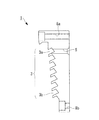
FIG. 1 is a longitudinal sectional view of an exhaust turbine supercharger (supercharger) 10 according to this embodiment. The
タービン19は外周部に多数のブレード19aを有している。このブレード19aは、ガス入口ケーシング11に設けられた排気ガス導入路22と、ガス出口ケーシング12に設けられた排気ガス排出路23との間に配置されている。
一方、羽根車20は、空気案内ケーシング14に設けられた吸入空気導入路24の後方に配置されている。吸入空気導入路24は、羽根車20を介して渦巻き室25に接続され、さらに渦巻き室25は図示しない吸入空気導入路を介してエンジンの燃焼室に接続されている。
なお、符号26は吸入空気が吸入空気導入路24に吸入される前段で吸入空気を通過させることで吸入空気を整流するフィルタである。
The
On the other hand, the
Reference numeral 26 denotes a filter that rectifies the intake air by allowing the intake air to pass through before the intake air is drawn into the intake
また、軸受台13には潤滑油供給通路27が形成されており、この潤滑油供給通路27の基端部はエンジンのオイルポンプ(図示せず)に接続されている。一方、潤滑油供給通路27の他端部は、スラスト軸受16およびラジアル軸受17,18にそれぞれ接続される分岐通路28,29,30に分岐している。
Further, a lubricating
さらに、軸受台13における羽根車20側の端部には、羽根車20の背面側に位置する壁部と羽根車20の背面との間をシールするラビリンスシール部1が設けられている。ラビリンスシール部1は、羽根車20に摺接することで圧縮後の空気の漏洩を防止している。
Furthermore, the
このような構成からなる排気タービン過給機10の作動時において、例えば舶用ディーゼル機関からの排気ガスは、排気ガス導入路22を通り、タービンノズルで静圧膨張された軸方向の排気ガス流によりタービン19が回転駆動される。そして、タービン19を駆動した排気ガスは、排気ガス排出路23から外部に排出される。
タービン19の回転は、タービンロータ軸15を介して羽根車20を回転させ、入空気導入路24を通って吸入された空気は、羽根車20で加圧され、ディフューザ33および出口スクロール35を通って、舶用ディーゼル機関に供給される。
During the operation of the
The rotation of the
次に、ラビリンスシール部1の構成について詳細に説明する。
図2に示されているように、ラビリンスシール部1は、軸線Lを中心軸線とするリング形状とされており、例えばSS400鋼材が好適に用いられる。
ラビリンスシール部1は、軸線Lに略平行に設けられた複数の外周ボルト穴8a及び複数の内周ボルト穴8bのそれぞれにボルトを挿通させることにより、ケーシング本体37(図1参照)へ固定されている(なお、ボルトによりラビリンスシール部1が固定された状態は図4に示されている)。外周ボルト穴8a及び内周ボルト穴8bは、ラビリンスシール部1の全周に渡り略等間隔で設けられている。
図3に拡大して示されているように、ラビリンスシール部1の一方の端面すなわち羽根車20に対向する端面には、複数段のラビリンス溝3が形成されている。ラビリンス溝3は、軸線Lを中心とする複数の円周溝とされている。ここで、各々のラビリンス溝3の溝寸法(溝深さ及び溝幅)は略等しく設けられている。
Next, the configuration of the
As shown in FIG. 2, the
The
As shown in an enlarged view in FIG. 3, a plurality of
図4に示されているように、ラビリンスシール部1の背面(図4において右側)には、冷却媒体が流通する環状空間7が形成されている。この環状空間7には,主機関より供給された冷却媒体が過給機側面部の軸受台13から取り込まれるようになっている。この環状空間7は、軸線Lを中心軸線とする環状形となっており、ラビリンスシール部1の背面に向けて開口するように形成されている。ここで、図4において、環状空間7は縦断面が略長方形形状とされている。さらに、環状空間7の縦寸法すなわち軸線Lに対して直交する方向(同図縦方向)の長さは、複数(図4に示した実施形態では4つ)のラビリンス溝3を覆う程度の長さとなっている。なお、この環状空間7の縦寸法は、必要空気量に応じて適宜設定される。
As shown in FIG. 4, an
ラビリンスシール部1には、ラビリンス溝3が形成された端面(以下「前面」という。)とは反対側の端面(図4において右側の端面)から前面に向かって形成された冷却穴5が設けられている。この冷却穴5は、軸線Lと略平行に延在しており、最外周溝3aと、背面に面した環状空間7とを接続している。ここで、冷却穴5の径は最外周溝3aの径より小さい径となっている。なお、図3に示すように、冷却穴5の背面側には、環状空間7に向かって拡径するテーパ加工が施されており、環状空間7からの空気流れが円滑になるような形状とされている。
冷却穴5は、図2(b)に示されているように、ラビリンスシール部1の全周に渡り略等間隔で例えば24箇所設けられている。
The
As shown in FIG. 2B, for example, 24
図5には、横軸を冷却空気挿入位置、縦軸を羽根車メタル温度(相対比較)として、冷却穴挿入位置と羽根車メタル温度の関係を表したグラフが示されている。同図に示されているように、羽根車最外周部におけるメタル温度が最も高く、次いで中間位置(羽根車20において、最外周部と最内周部との中間)のメタル温度、最後に中心付近(羽根車20におけるロータ軸15付近)におけるメタル温度の順となっている。
また、1段目(最外周溝3aと環状空間7を接続する冷却穴5)に冷却空気を挿入するのが最も冷却効果が高く、ついで2段目(軸線Lに対して最外周溝3aの一つ内周側に位置する冷却穴5)、最後に3段目(軸線Lに対して最外周溝3aの二つ内周側に位置する冷却穴5)の順になっている。
さらに、1段目の冷却穴5に冷却空気を挿入した場合は、2段目及び3段目の冷却穴5に冷却空気を挿入した場合に比べ、冷却効果が顕著に高いことがわかる。これは、2段目及び3段目から冷却空気を挿入すると、羽根車外周部から羽根車背面に入り込む空気が摩擦により高温となり、1段目から冷却空気を挿入する場合に比べて入熱量が多くなるためである。
FIG. 5 is a graph showing the relationship between the cooling hole insertion position and the impeller metal temperature, with the horizontal axis representing the cooling air insertion position and the vertical axis representing the impeller metal temperature (relative comparison). As shown in the figure, the metal temperature at the outermost periphery of the impeller is the highest, and then the metal temperature at the intermediate position (in the
Further, the cooling effect is most effective when the cooling air is inserted into the first stage (the
Further, it can be seen that the cooling effect is significantly higher when the cooling air is inserted into the first-
以上に説明の構成により、本実施形態によれば、以下の作用効果を奏する。
冷却媒体が流通する環状空間7をラビリンスシール部1の背面側に設けかつ冷却穴5を環状空間7と最外周溝3aとを接続するように設けたため、シール空気を環状空間7において周方向に流すことで均一化し、その後ラビリンスシール部1が有する24箇所の冷却穴5から最外周溝3aへ冷却空気を供給することができる。これにより、ラビリンス溝3の数を減らす必要がなくなり、ラビリンスシール部1のシール性を確保しつつ、冷却を行わない場合と比較して、約230℃まで上昇した羽根車20のメタル温度を約7℃低下させることができる。
With the configuration described above, according to the present embodiment, the following operational effects can be obtained.
Since the
なお、上述した本実施形態では、複数のラビリンス溝3において、最外周溝3aに、冷却穴5が接続されているとして説明した。しかし、本発明はこれに限定されるものではなく、例えば最外周溝3aの一つ内周側に位置するラビリンス溝3に接続してもよい。
また、上述した各実施形態では、ラビリンスシール部1の穴の数が24箇所として説明した。しかし、本発明はこれに限定されるものではなく、冷却効果を考慮して決定され、例えば12箇所若しくは36箇所のような偶数箇所又は21箇所のような奇数箇所であっても良い。
また、上述した各実施形態では、ラビリンスシール部1の素材をSS400として説明した。しかし、本発明はこれに限定されるものではなく、例えばSS490又はSS540等の鋼材であっても良い。
また、冷却穴5は軸線Lと略平行に設けてあると説明した。しかし、本発明はこれに限定されるものではなく、冷却穴5はラビリンス溝3と環状空間7を接続してさえいればよく、例えば軸線Lに対して斜めであってもよい。
また、上述した各実施形態では、冷却媒体として空気を用いることとした。しかし、本発明はこれに限定されるものではなく、例えば水蒸気を用いてもよい。
In the above-described embodiment, the
Moreover, in each embodiment mentioned above, the number of holes of the
Moreover, in each embodiment mentioned above, the raw material of the
It has been described that the
Moreover, in each embodiment mentioned above, we decided to use air as a cooling medium. However, the present invention is not limited to this, and for example, water vapor may be used.
1 ラビリンスシール部
3 ラビリンス溝
3a 最外周溝(軸線を中心とする半径方向最外側に位置するラビリンス溝)
5 冷却穴
7 環状空間
8a 外周ボルト穴
8b 内周ボルト穴
10 排気タービン過給機
11 ガス入口ケーシング
12 ガス出口ケーシング
13 軸受台
14 コンプレッサ側空気案内ケーシング
15 ロータ軸
16 スラスト軸受
17、18 ラジアル軸受
19 タービン
19a ブレード
20 羽根車
22 排気ガス導入路
23 排気ガス排出路
24 吸入空気導入路
25 渦巻き室
26 フィルタ
27 潤滑油供給通路
28、29、30 分岐通路
31 コンプレッサハウジング
33 ディフューザ
35 出口スクロール
37 ケーシング本体
L 軸線
DESCRIPTION OF
DESCRIPTION OF
Claims (6)
該羽根車の背面側に位置する壁部と該羽根車の背面との間をシールするラビリンスシール部と、
を備えた遠心圧縮機において、
前記ラビリンスシール部は、前記軸線を中心とする複数の円周溝とされたラビリンス溝を有し、
複数の前記ラビリンス溝の少なくとも1つには、冷却媒体を流通させる冷却穴が接続されていることを特徴とする遠心圧縮機。 An impeller that rotates about an axis;
A labyrinth seal portion that seals between the wall portion located on the back side of the impeller and the back surface of the impeller;
In a centrifugal compressor with
The labyrinth seal part has a labyrinth groove that is a plurality of circumferential grooves around the axis,
A centrifugal compressor, wherein a cooling hole for circulating a cooling medium is connected to at least one of the plurality of labyrinth grooves.
前記冷却穴は、前記環状空間と前記ラビリンス溝とを接続するように、それぞれが離間した状態で複数形成されていることを特徴とする請求項1に記載の遠心圧縮機。 An annular space through which the cooling medium flows is provided on the back side of the labyrinth seal portion,
2. The centrifugal compressor according to claim 1, wherein a plurality of the cooling holes are formed in a separated state so as to connect the annular space and the labyrinth groove.
該遠心圧縮機を駆動する排気タービンと、
を備えていることを特徴とする過給機。 The centrifugal compressor according to any one of claims 1 to 3,
An exhaust turbine for driving the centrifugal compressor;
A turbocharger characterized by comprising:
前記羽根車の背面に位置するラビリンスシール部に設けられた前記軸線を中心とする複数の円周溝とされたラビリンス溝の少なくとも1つに冷却媒体を流通させる冷却媒体流通工程と、
を備えたことを特徴とする遠心圧縮機の運転方法。 An impeller rotation process in which an impeller rotates around an axis by rotation of an exhaust turbine;
A cooling medium flow step for flowing a cooling medium in at least one of the labyrinth grooves formed as a plurality of circumferential grooves around the axis provided in the labyrinth seal portion located on the back surface of the impeller; and
A method for operating a centrifugal compressor, comprising:
Priority Applications (5)
| Application Number | Priority Date | Filing Date | Title |
|---|---|---|---|
| JP2012266274A JP2014111905A (en) | 2012-12-05 | 2012-12-05 | Centrifugal compressor and supercharger with the same, and operation method for centrifugal compressor |
| KR1020157014736A KR20150081342A (en) | 2012-12-05 | 2013-12-02 | Centrifugal compressor, supercharger with same, and method for operating centrifugal compressor |
| PCT/JP2013/082346 WO2014087966A1 (en) | 2012-12-05 | 2013-12-02 | Centrifugal compressor, supercharger with same, and method for operating centrifugal compressor |
| EP13861290.8A EP2930370A4 (en) | 2012-12-05 | 2013-12-02 | Centrifugal compressor, supercharger with same, and method for operating centrifugal compressor |
| CN201380063139.4A CN104903586A (en) | 2012-12-05 | 2013-12-02 | Centrifugal compressor, supercharger with same, and method for operating centrifugal compressor |
Applications Claiming Priority (1)
| Application Number | Priority Date | Filing Date | Title |
|---|---|---|---|
| JP2012266274A JP2014111905A (en) | 2012-12-05 | 2012-12-05 | Centrifugal compressor and supercharger with the same, and operation method for centrifugal compressor |
Publications (2)
| Publication Number | Publication Date |
|---|---|
| JP2014111905A true JP2014111905A (en) | 2014-06-19 |
| JP2014111905A5 JP2014111905A5 (en) | 2015-08-06 |
Family
ID=50883383
Family Applications (1)
| Application Number | Title | Priority Date | Filing Date |
|---|---|---|---|
| JP2012266274A Pending JP2014111905A (en) | 2012-12-05 | 2012-12-05 | Centrifugal compressor and supercharger with the same, and operation method for centrifugal compressor |
Country Status (5)
| Country | Link |
|---|---|
| EP (1) | EP2930370A4 (en) |
| JP (1) | JP2014111905A (en) |
| KR (1) | KR20150081342A (en) |
| CN (1) | CN104903586A (en) |
| WO (1) | WO2014087966A1 (en) |
Cited By (5)
| Publication number | Priority date | Publication date | Assignee | Title |
|---|---|---|---|---|
| JP2016089717A (en) * | 2014-11-05 | 2016-05-23 | 三菱重工業株式会社 | Centrifugal compressor and supercharger including the same |
| WO2016121653A1 (en) * | 2015-01-26 | 2016-08-04 | 三菱重工業株式会社 | Intake-air-straightening device and compressor provided with same |
| WO2016121678A1 (en) * | 2015-01-26 | 2016-08-04 | 三菱重工業株式会社 | Exhaust turbine supercharger |
| JP2021134754A (en) * | 2020-02-28 | 2021-09-13 | 三菱重工マリンマシナリ株式会社 | Supercharger |
| KR20230131946A (en) | 2021-04-01 | 2023-09-14 | 미쓰비시주코마린마시나리 가부시키가이샤 | supercharger |
Families Citing this family (3)
| Publication number | Priority date | Publication date | Assignee | Title |
|---|---|---|---|---|
| DE102014226951A1 (en) * | 2014-12-23 | 2016-06-23 | Robert Bosch Gmbh | turbomachinery |
| JP6246847B2 (en) | 2016-02-22 | 2017-12-13 | 三菱重工業株式会社 | Impeller back cooling structure and turbocharger |
| CN110671157A (en) * | 2019-11-22 | 2020-01-10 | 东方电气集团东方汽轮机有限公司 | Radial steam seal structure for radial turbine and radial turbine |
Citations (2)
| Publication number | Priority date | Publication date | Assignee | Title |
|---|---|---|---|---|
| JP2008045425A (en) * | 2006-08-11 | 2008-02-28 | Mitsubishi Heavy Ind Ltd | Centrifugal compressor |
| JP2010506091A (en) * | 2006-10-12 | 2010-02-25 | エムアーエヌ・ディーゼル・エスエー | Compressor for turbocharger and cooling method thereof |
Family Cites Families (3)
| Publication number | Priority date | Publication date | Assignee | Title |
|---|---|---|---|---|
| JP2934530B2 (en) | 1991-06-14 | 1999-08-16 | 三菱重工業株式会社 | Centrifugal compressor |
| DE59809488D1 (en) | 1998-05-25 | 2003-10-09 | Abb Turbo Systems Ag Baden | centrifugal compressors |
| EP2067999A1 (en) * | 2007-12-06 | 2009-06-10 | Napier Turbochargers Limited | Liquid cooled turbocharger impeller and method for cooling an impeller |
-
2012
- 2012-12-05 JP JP2012266274A patent/JP2014111905A/en active Pending
-
2013
- 2013-12-02 WO PCT/JP2013/082346 patent/WO2014087966A1/en active Application Filing
- 2013-12-02 CN CN201380063139.4A patent/CN104903586A/en active Pending
- 2013-12-02 KR KR1020157014736A patent/KR20150081342A/en active Search and Examination
- 2013-12-02 EP EP13861290.8A patent/EP2930370A4/en not_active Withdrawn
Patent Citations (2)
| Publication number | Priority date | Publication date | Assignee | Title |
|---|---|---|---|---|
| JP2008045425A (en) * | 2006-08-11 | 2008-02-28 | Mitsubishi Heavy Ind Ltd | Centrifugal compressor |
| JP2010506091A (en) * | 2006-10-12 | 2010-02-25 | エムアーエヌ・ディーゼル・エスエー | Compressor for turbocharger and cooling method thereof |
Cited By (8)
| Publication number | Priority date | Publication date | Assignee | Title |
|---|---|---|---|---|
| JP2016089717A (en) * | 2014-11-05 | 2016-05-23 | 三菱重工業株式会社 | Centrifugal compressor and supercharger including the same |
| WO2016121653A1 (en) * | 2015-01-26 | 2016-08-04 | 三菱重工業株式会社 | Intake-air-straightening device and compressor provided with same |
| WO2016121678A1 (en) * | 2015-01-26 | 2016-08-04 | 三菱重工業株式会社 | Exhaust turbine supercharger |
| JP2016138464A (en) * | 2015-01-26 | 2016-08-04 | 三菱重工業株式会社 | Exhaust turbine supercharger |
| CN107208548A (en) * | 2015-01-26 | 2017-09-26 | 三菱重工业株式会社 | Exhaust-driven turbo-charger exhaust-gas turbo charger |
| JP2021134754A (en) * | 2020-02-28 | 2021-09-13 | 三菱重工マリンマシナリ株式会社 | Supercharger |
| JP7105823B2 (en) | 2020-02-28 | 2022-07-25 | 三菱重工マリンマシナリ株式会社 | supercharger |
| KR20230131946A (en) | 2021-04-01 | 2023-09-14 | 미쓰비시주코마린마시나리 가부시키가이샤 | supercharger |
Also Published As
| Publication number | Publication date |
|---|---|
| CN104903586A (en) | 2015-09-09 |
| WO2014087966A1 (en) | 2014-06-12 |
| EP2930370A4 (en) | 2015-12-02 |
| KR20150081342A (en) | 2015-07-13 |
| EP2930370A1 (en) | 2015-10-14 |
Similar Documents
| Publication | Publication Date | Title |
|---|---|---|
| JP2014111905A (en) | Centrifugal compressor and supercharger with the same, and operation method for centrifugal compressor | |
| US10526907B2 (en) | Internally cooled seal runner | |
| JP5460294B2 (en) | Centrifugal compressor forward thrust and turbine cooling system | |
| JP5721945B2 (en) | Turbine cooling air from a centrifugal compressor | |
| US8262342B2 (en) | Gas turbine engine assemblies with recirculated hot gas ingestion | |
| JP4040556B2 (en) | Gas turbine equipment and cooling air supply method | |
| JP5538240B2 (en) | Impeller and turbocharger | |
| US8186938B2 (en) | Turbine apparatus | |
| JP2017048781A (en) | Hydrodynamic seals in bearing compartments of gas turbine engines | |
| JP2000054997A (en) | Centrifugal compressor | |
| CN107849973B (en) | Impeller back surface cooling structure and supercharger | |
| JP2009243299A (en) | Turbocharger | |
| KR101382309B1 (en) | Bearing of turbo-charger | |
| WO2016067715A1 (en) | Supercharger and engine with same | |
| US10815829B2 (en) | Turbine housing assembly | |
| JP2005163641A (en) | Turbocharger | |
| US7036320B2 (en) | Gas turbine with stator shroud in the cavity beneath the chamber | |
| US11339663B2 (en) | Rotor having improved structure, and turbine and gas turbine including the same | |
| JP7105823B2 (en) | supercharger | |
| WO2022208839A1 (en) | Supercharger | |
| JP2005098267A (en) | Supercharger | |
| KR101339280B1 (en) | Sealing bracket of electric turbo-charger | |
| JP2007321654A (en) | Supercharger | |
| JP2005194914A (en) | Sealing structure and turbine nozzle |
Legal Events
| Date | Code | Title | Description |
|---|---|---|---|
| A521 | Written amendment |
Free format text: JAPANESE INTERMEDIATE CODE: A523 Effective date: 20150618 |
|
| A621 | Written request for application examination |
Free format text: JAPANESE INTERMEDIATE CODE: A621 Effective date: 20150618 |
|
| A871 | Explanation of circumstances concerning accelerated examination |
Free format text: JAPANESE INTERMEDIATE CODE: A871 Effective date: 20150618 |
|
| A975 | Report on accelerated examination |
Free format text: JAPANESE INTERMEDIATE CODE: A971005 Effective date: 20150629 |
|
| A131 | Notification of reasons for refusal |
Free format text: JAPANESE INTERMEDIATE CODE: A131 Effective date: 20150804 |
|
| A02 | Decision of refusal |
Free format text: JAPANESE INTERMEDIATE CODE: A02 Effective date: 20151222 |