RU2476710C2 - Rotor ring seal in turbine stage - Google Patents
Rotor ring seal in turbine stage Download PDFInfo
- Publication number
- RU2476710C2 RU2476710C2 RU2008144750/06A RU2008144750A RU2476710C2 RU 2476710 C2 RU2476710 C2 RU 2476710C2 RU 2008144750/06 A RU2008144750/06 A RU 2008144750/06A RU 2008144750 A RU2008144750 A RU 2008144750A RU 2476710 C2 RU2476710 C2 RU 2476710C2
- Authority
- RU
- Russia
- Prior art keywords
- sheet
- ring
- nozzle apparatus
- annular
- turbine
- Prior art date
Links
Images
Classifications
-
- F—MECHANICAL ENGINEERING; LIGHTING; HEATING; WEAPONS; BLASTING
- F01—MACHINES OR ENGINES IN GENERAL; ENGINE PLANTS IN GENERAL; STEAM ENGINES
- F01D—NON-POSITIVE DISPLACEMENT MACHINES OR ENGINES, e.g. STEAM TURBINES
- F01D11/00—Preventing or minimising internal leakage of working-fluid, e.g. between stages
- F01D11/005—Sealing means between non relatively rotating elements
-
- F—MECHANICAL ENGINEERING; LIGHTING; HEATING; WEAPONS; BLASTING
- F05—INDEXING SCHEMES RELATING TO ENGINES OR PUMPS IN VARIOUS SUBCLASSES OF CLASSES F01-F04
- F05D—INDEXING SCHEME FOR ASPECTS RELATING TO NON-POSITIVE-DISPLACEMENT MACHINES OR ENGINES, GAS-TURBINES OR JET-PROPULSION PLANTS
- F05D2240/00—Components
- F05D2240/10—Stators
- F05D2240/11—Shroud seal segments
Abstract
Description
Настоящее изобретение касается уплотнения кольца ротора в ступени турбины турбомашины, такого как авиационный турбореактивный или турбовинтовой двигатель.The present invention relates to sealing a rotor ring in a turbine stage of a turbomachine, such as an aircraft turbojet or turboprop.
Обычно турбина турбомашины содержит, по меньшей мере, одну ступень, состоящую из соплового аппарата, который образован кольцевым рядом неподвижных лопаток и за которым находится колесо ротора, установленное внутри разделенного на сектора кольца. Сопловой аппарат на своем заднем конце содержит кольцевой бортик, который проходит радиально наружу, на котором находятся средства крепления на корпусе турбины. Разделенное на сектора кольцо, расположенное дальше к выходу, содержит передний цилиндрический бортик, который удерживается радиально на направляющей корпуса турбины посредством кольцевого органа стопорения с сечением С-образной или U-образной формы, заходящего в осевом направлении на направляющую корпуса и на цилиндрический бортик кольца.Typically, a turbomachine turbine comprises at least one stage consisting of a nozzle apparatus, which is formed by an annular row of fixed blades and behind which is a rotor wheel mounted inside a sectorized ring. The nozzle apparatus at its rear end comprises an annular rim that extends radially outward, on which are fastening means on the turbine housing. The sectorized ring, located further to the exit, contains a front cylindrical rim that is held radially on the guide of the turbine housing by means of an annular locking member with a cross section of a C-shape or U-shape, axially extending to the housing guide and to the cylindrical rim of the ring.
Как правило, цилиндрический бортик кольца и направляющая корпуса защищены термически кольцевым листом, который установлен между наружным бортиком соплового аппарата и передним концом кольца для ограничения прохождения газов из газо-воздушного тракта турбины радиально наружу в кольцевое пространство размещения бортика кольца и направляющей корпуса.As a rule, the cylindrical rim of the ring and the housing guide are protected by a thermally annular sheet, which is installed between the outer rim of the nozzle apparatus and the front end of the ring to restrict the passage of gases from the gas-air path of the turbine radially outward into the annular space of the ring rim and the housing guide.
Однако в данном случае уплотнение не является идеальным, и утечки горячих газов, поступающих из газовоздушного тракта турбины, могут привести к повышению температуры крюков корпуса и к образованию изломов или трещин, которые могут вызвать разрушение крюков.However, in this case, the seal is not ideal, and the leakage of hot gases from the turbine’s air duct can lead to an increase in the temperature of the body hooks and the formation of kinks or cracks that can cause the hooks to break.
Кроме того, как правило, лопатки соплового аппарата содержат каналы протекания охлаждающего воздуха, отбираемого на входе из компрессора турбомашины.In addition, as a rule, the blades of the nozzle apparatus contain channels for the flow of cooling air, taken at the inlet from the compressor of the turbomachine.
Как известно, часть воздуха, циркулирующего в каналах этих лопаток, отбирают и направляют в кольцевое пространство размещения переднего бортика кольца и направляющей корпуса для понижения их температуры. Нагнетание воздуха в это пространство позволяет также поддерживать в этом пространстве давление, превышающее давление газообразных продуктов сгорания, проходящих через турбину, что ограничивает попадание этих газов в кольцевое пространство.As you know, part of the air circulating in the channels of these blades is taken and sent to the annular space of the front side of the ring and the guide body to lower their temperature. The injection of air into this space also allows maintaining in this space a pressure exceeding the pressure of the gaseous products of combustion passing through the turbine, which limits the entry of these gases into the annular space.
Однако при недостаточном уплотнении между наружным бортиком соплового аппарата и передним концом кольца охлаждающий воздух, нагнетаемый в кольцевое пространство размещения переднего бортика кольца и направляющей корпуса, стремится пройти в радиальном направлении снаружи внутрь в газовоздушный тракт турбины и, следовательно, не участвует в охлаждении корпуса и кольца.However, if there is insufficient sealing between the outer side of the nozzle apparatus and the front end of the ring, the cooling air pumped into the annular space of the front side of the ring and the housing guide tends to pass radially from the outside inward into the gas-air path of the turbine and, therefore, is not involved in cooling the case and ring .
Настоящее изобретение призвано предложить простое, экономичное и эффективное решение этой проблемы.The present invention is intended to offer a simple, economical and effective solution to this problem.
Объектом изобретения является ступень турбины, содержащая средства уплотнения между сопловым аппаратом и разделенным на сектора кольцом, которые являются простыми и эффективными и препятствуют прохождению газов в радиальном направлении между наружным бортиком соплового аппарата и передним концом кольца.The object of the invention is a turbine stage, containing sealing means between the nozzle apparatus and the sectorized ring, which are simple and efficient and prevent the passage of gases in the radial direction between the outer rim of the nozzle apparatus and the front end of the ring.
В этой связи изобретением предлагается ступень турбины турбомашины, содержащая колесо ротора, установленное внутри разделенного на сектора кольца, установленного на корпусе турбины, сопловой аппарат, расположенный на входе колеса и образованный кольцевым рядом неподвижных лопаток, при этом сопловой аппарат содержит на своем заднем конце наружный кольцевой бортик, содержащий средства крепления на корпусе турбины, при этом между наружным бортиком соплового аппарата и передним концом кольца предусмотрены средства уплотнения для ограничения прохождения газов в радиальном направлении между наружным бортиком соплового аппарата и кольцом, отличающаяся тем, что средства уплотнения содержат кольцевой лист, который проходит по существу радиально между наружным бортиком соплового аппарата и передним концом кольца и содержит на своей внутренней периферии и на своей наружной периферии средства осевой опоры на заднюю сторону наружного бортика соплового аппарата, при этом серединная кольцевая часть этого листа отстоит в осевом направлении от наружного бортика соплового аппарата и опирается в осевом направлении на передний конец кольца, при этом лист подвергается предварительному упругому напряжению в осевом направлении со стороны переднего конца кольца.In this regard, the invention proposes a turbine stage of a turbomachine, comprising a rotor wheel mounted inside a sectorized ring mounted on the turbine housing, a nozzle device located at the wheel inlet and formed by an annular row of fixed vanes, while the nozzle apparatus comprises an outer annular at its rear end a flange containing fastening means on the turbine housing, while sealing means are provided between the outer flange of the nozzle apparatus and the front end of the ring the passage of gases in the radial direction between the outer rim of the nozzle apparatus and the ring, characterized in that the sealing means comprise an annular sheet that extends essentially radially between the outer rim of the nozzle apparatus and the front end of the ring and contains means on its inner periphery and on its outer periphery axial support on the rear side of the outer side of the nozzle apparatus, while the middle annular part of this sheet is axially spaced from the outer side of the nozzle app rata and rests axially on the front end of the ring, wherein the sheet is pre-elastic stress in the axial direction from the front end of the ring.
Лист уплотнения в соответствии с настоящим изобретением опирается в осевом направлении от входа по своей внутренней периферии и по своей наружной периферии на бортик соплового аппарата, а его серединная кольцевая часть упруго опирается на передний конец кольца. Три кольцевые зоны опоры листа на бортик соплового аппарата и на кольцо обеспечивают хорошее уплотнение между этими элементами и препятствуют прохождению газов из тракта турбины наружу в кольцевое пространство размещения бортика кольца и направляющей корпуса и утечкам воздуха из этого пространства внутрь в тракт турбины.The seal sheet in accordance with the present invention is supported axially from the entrance on its inner periphery and on its outer periphery on the side of the nozzle apparatus, and its middle annular part is elastically supported on the front end of the ring. The three annular zones of support of the sheet on the side of the nozzle apparatus and on the ring provide a good seal between these elements and prevent the passage of gases from the turbine path outward to the annular space of the side of the ring and the guide body and air leaks from this space inward to the turbine path.
Кольцо упирается своим передним концом в серединную часть листа, который, в свою очередь, опирается на бортик соплового аппарата, что выражается небольшой упругой деформацией изгиба листа. Эта деформация возможна за счет осевого пространства, предусмотренного между наружным бортиком соплового аппарата и уплотнительным листом, на уровне серединной кольцевой части этого листа.The ring abuts with its front end in the middle part of the sheet, which, in turn, rests on the side of the nozzle apparatus, which is expressed by a slight elastic deformation of the bend of the sheet. This deformation is possible due to the axial space provided between the outer side of the nozzle apparatus and the sealing sheet, at the level of the middle annular part of this sheet.
Это предварительное осевое напряжение определяют таким образом, чтобы сгладить допуски на обработку различных деталей и чтобы во время работы сохранить три вышеуказанных опорных положения, несмотря на дифференциальные тепловые расширения различных деталей. Деформация изгиба листа может быть, таким образом, более или менее значительной на разных режимах работы турбины.This pre-axial stress is determined in such a way as to smooth the tolerances on the processing of various parts and in order to maintain the above three support positions during operation, despite the differential thermal expansion of the various parts. The bending deformation of the sheet can thus be more or less significant at different turbine operating conditions.
Предпочтительно лист крепят, например, при помощи заклепок на наружном бортике соплового аппарата. Лист крепят, например, его внутренней периферией на радиально внутренней концевой части наружного бортика соплового аппарата.Preferably, the sheet is fastened, for example, with rivets on the outer edge of the nozzle apparatus. The sheet is fixed, for example, by its inner periphery on the radially inner end portion of the outer rim of the nozzle apparatus.
В варианте выполнения изобретения лист по существу является плоским и в монтажном положении прижимается к задней стороне наружного бортика соплового аппарата, перекрывая кольцевой желобок этой задней стороны.In an embodiment of the invention, the sheet is essentially flat and in the mounting position is pressed against the rear side of the outer side of the nozzle apparatus, overlapping the annular groove of this rear side.
Кольцевой желобок задней стороны наружного бортика соплового аппарата позволяет определить осевое кольцевое пространство между бортиком соплового аппарата и серединной кольцевой частью листа, позволяя, таким образом, упругую деформацию изгиба листа. Этот желобок разбит на сектора, как и сопловой аппарат, и может быть по существу расположен на 360° вокруг оси турбины, и она перекрывается листом, опирающимся на наружный бортик соплового аппарата радиально внутри и снаружи этого желобка.The annular groove of the rear side of the outer rim of the nozzle apparatus allows the axial annular space to be defined between the rim of the nozzle apparatus and the middle annular part of the sheet, thereby allowing elastic deformation of the bending of the sheet. This groove is divided into sectors, like the nozzle apparatus, and can be essentially located 360 ° around the axis of the turbine, and it is overlapped by a sheet resting on the outer rim of the nozzle apparatus radially inside and outside this groove.
Согласно другому варианту выполнения изобретения, кольцевой лист не является плоским, а является изогнутым и имеет вогнутость, направленную в сторону входа. Он содержит, например, кольцевую часть, имеющую сечение U-образной или V-образной формы, отверстие которой направлено вперед, причем эта кольцевая часть опирается в осевом направлении на передний конец кольца и определяет кольцевое пространство вместе с задней стороной наружного бортика соплового аппарата.According to another embodiment of the invention, the annular sheet is not flat, but curved and has a concavity directed towards the entrance. It contains, for example, an annular part having a U-shaped or V-shaped cross-section, the opening of which is directed forward, and this annular part is axially supported on the front end of the ring and defines the annular space together with the rear side of the outer rim of the nozzle apparatus.
Лист уплотнения разбит на сектора, как и сопловой аппарат, и может располагаться на 360° вокруг оси турбины. Предпочтительно он является металлическим.The seal sheet is divided into sectors, like the nozzle apparatus, and can be located 360 ° around the axis of the turbine. Preferably, it is metallic.
Объектом изобретения является также турбина турбомашины, отличающаяся тем, что содержит, по меньшей мере, одну описанную выше ступень.An object of the invention is also a turbine of a turbomachine, characterized in that it comprises at least one stage described above.
Объектом изобретения является также турбомашина, такая как авиационный турбореактивный или турбовинтовой двигатель, отличающаяся тем, что содержит, по меньшей мере, одну описанную выше ступень.The invention also relates to a turbomachine, such as an aircraft turbojet or turboprop engine, characterized in that it comprises at least one stage described above.
Изобретение и его другие отличительные признаки, детали и преимущества будут более очевидны из нижеследующего описания, представленного в качестве не ограничительного примера, со ссылками на прилагаемые чертежи, на которых:The invention and its other distinctive features, details and advantages will be more apparent from the following description, presented by way of non-limiting example, with reference to the accompanying drawings, in which:
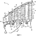
фиг. 1 - схематичный частичный вид в осевом разрезе турбины турбомашины;FIG. 1 is a schematic partial axial sectional view of a turbomachine turbine;
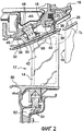
фиг. 2 - увеличенный вид части, показанной на фиг. 1, иллюстрирующий ступень турбины из предшествующего уровня техники;FIG. 2 is an enlarged view of the part shown in FIG. 1 illustrating a turbine stage of the prior art;
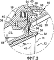
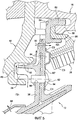
фиг. 3 - увеличенный вид детали I3, показанной на фиг. 2;FIG. 3 is an enlarged view of part I 3 shown in FIG. 2;
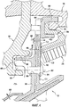
фиг. 4 - схематичный частичный вид в осевом разрезе ступени турбины в соответствии с настоящим изобретением;FIG. 4 is a schematic partial axial sectional view of a turbine stage in accordance with the present invention;
фиг. 5 - вид, соответствующий фиг. 4 и иллюстрирующий вариант выполнения изобретения.FIG. 5 is a view corresponding to FIG. 4 and illustrating an embodiment of the invention.
На фиг. 1 показана турбина 10 низкого давления турбомашины, содержащая четыре ступени, каждая из которых содержит сопловой аппарат 12, образованный кольцевым рядом неподвижных лопаток 14, установленных на наружном корпусе 16 турбины, и колесо 18, находящееся на выходе соплового аппарата 12.In FIG. 1 shows a low-
Колеса 18 содержат диски 20, соединенные друг с другом в осевом направлении при помощи кольцевых фланцев 22 и несущие на себе радиальные лопатки 24. Эти колеса 18 соединены с валом турбины (не показан) при помощи приводного конуса 26, закрепленного на кольцевых фланцах 22 дисков.The
Каждое колесо 18 снаружи окружено с небольшим зазором кольцом 28, образованным секторами, закрепленными в окружном направлении на корпусе 16 турбины при помощи органов стопорения, что будет подробнее описано ниже.Each
Сопловые аппараты 12 содержат соответственно внутреннюю 30 и наружную 32 круглые стенки, которые ограничивают между собой кольцевой газовоздушный тракт в турбине и между которыми в радиальном направлении расположены лопатки 14.The
Наружная стенка 32 соплового аппарата 16 входной ступени, более детально показанная на фиг. 2, содержит радиально наружные передний 34 и задний 36 кольцевые бортики, содержащие осевые кольцевые крепежные лапки 38, направленные в сторону входа и предназначенные для установки в соответствующие осевые кольцевые желобки 40 корпуса 16 турбины.The
Лопатки 14 этого соплового аппарата 12 содержат каналы 42 для циркуляции охлаждающего воздуха, поступающего из камеры 44 питания (стрелки 46), находящейся радиально снаружи стенки 32 соплового аппарата. Этот воздух частично удаляется в газовоздушный тракт турбины через отверстия (не показаны), выполненные вблизи задней кромки лопаток 14 и выходящие в их каналы 42, и частично - в камеру 52, находящуюся радиально внутри стенки 30 соплового аппарата (стрелки 54). Охлаждающий воздух отбирается на входе из компрессора турбомашины и подается в камеру 44 питания при помощи соответствующих средств.The
Кольцо 28, находящееся на выходе соплового аппарата 12 входной ступени, содержит на своем переднем конце кольцевой крюк 56, который накладывается на соответствующую цилиндрическую направляющую 58 корпуса 16 и который удерживается в радиальном направлении на этой направляющей при помощи кольцевого органа 60 стопорения с сечением С-образной или U-образной формы, который заходит в осевом направлении от входа на крюк 56 и направляющую 5 (фиг. 3).The
Орган 60, крюк 56 и направляющая 58 размещены в кольцевом пространстве 62, которое расположено вокруг кольца 28 между корпусом 16 и сопловым аппаратом 12. Орган 60 опирается своим передним концом на заднюю сторону 64 заднего кольцевого бортика 36 соплового аппарата.The
Орган 60, направляющая 58 корпуса и крюк 56 кольца защищены термически кольцевым листом 66, который установлен между передним концом кольца 28 и задней стороной 64 кольцевого бортика 36 соплового аппарата и предназначен для ограничения прохождения газа из тракта турбины радиально наружу в кольцевое пространство 62.The
Направляющая 58 корпуса и крюк 56 кольца во время работы подвергаются воздействию высоких температур, которые могут привести к образованию надрывов или трещин и к их разрушению.The
Чтобы решить эти проблемы, уже было предложено отбирать часть относительно прохладного воздуха, циркулирующего в каналах 42 лопаток соплового аппарата, и подавать этот воздух в кольцевое пространство 62, чтобы понижать температуру внутри этого пространства.To solve these problems, it has already been proposed to take part of the relatively cool air circulating in the
Для этого соответственно в наружной стенке 32 и в наружном бортике 36 соплового аппарата выполняют каналы 68 и 70 для соединения каналов 42 лопаток с кольцевым пространством 62. Каналы 68, выполненные в наружной стенке 32 соплового аппарата, сообщаются одним своим концом с каналом 42 лопатки и другим концом с кольцевым проходом 72, находящимся радиально снаружи стенки 32 соплового аппарата и ограниченным в осевом направлении наружными кольцевыми бортиками 34, 36 соплового аппарата. Каналы 70, выполненные в наружном бортике 36 соплового аппарата 12, являются наклонными относительно оси турбины и направлены сзади наружу. Они выходят своими передними концами в кольцевой проход 72 и своими задними концами на заднюю сторону 64 наружного бортика 36 соплового аппарата.For this, respectively, in the
Однако сам кольцевой лист 66 еще не обеспечивает достаточного уплотнения между сопловым аппаратом 12 и кольцом 28, что выражается в наличии утечек воздуха, нагнетаемого в кольцевое пространство 62, радиально внутрь в тракт турбины.However, the
Изобретение позволяет получить простое решение этой проблемы, благодаря новым средствам уплотнения.The invention provides a simple solution to this problem, thanks to new means of sealing.
Средства уплотнения в соответствии с настоящим изобретением содержат кольцевой лист 80, который проходит в радиальном направлении между наружным бортиком 36 соплового аппарата и передним концом кольца 28 и который подвергают предварительному напряжению в осевом направлении за счет опоры с передней стороны его внутренней периферии и его наружной периферии на заднюю сторону 64 бортика 36 и за счет опоры с задней стороны на уровне его серединной кольцевой части на передний конец кольца 28.The sealing means in accordance with the present invention comprise an
В примере, показанном на фиг. 4, кольцевой лист 80 уплотнения является по существу плоским и закреплен заклепками 82 на наружном бортике 36 соплового аппарата. Заклепки являются по существу параллельными оси турбины и проходят через отверстия 84, выполненные в радиально внутренней концевой части листа 80, и через соответствующие отверстия 86, выполненные в радиально внутренней концевой части бортика 36 соплового аппарата.In the example shown in FIG. 4, the
Лист 80 полностью перекрывает кольцевой желобок 88 задней стороны 64 бортика 36. Этот желобок 88 имеет небольшую осевую глубину, например, по существу равную толщине листа, и радиальный размер, немного меньший радиального размера листа 80. Он выполнен в секторах соплового аппарата по всему угловому расстоянию этих секторов и может располагаться на 360° вокруг оси турбины. Лист выполнен из угловых секторов, каждый из которых закреплен на секторе соплового аппарата и может располагаться на 360° вокруг оси турбины.The
Внутренняя периферия листа 80 расположена на окружности, находящейся радиально внутри желобка 88, и эта внутренняя периферия опирается в осевом направлении на радиально внутреннюю часть задней стороны 64 бортика 36. Наружная периферия листа расположена на окружности, находящейся радиально снаружи желобка, и эта периферия опирается в осевом направлении на радиально наружную часть задней стороны 64 бортика 36.The inner periphery of the
В представленном примере отверстия 84 и 86 для установки заклепок 82 выходят одним из своих концов в кольцевой желобок 88 вблизи его внутренней периферии и расположены радиально внутри кольца 28. Передний конец кольца 28 упирается в осевом направлении на лист 80 в зоне, находящейся между заклепками и наружной периферией желобка 88.In the presented example, the
В положении монтажа лист 80 предварительно упруго напряжен кольцом, которое действует достаточным усилием в осевом направлении в сторону входа на лист, чтобы он претерпел небольшую упругую деформацию изгиба. Предварительное осевое напряжение листа 80 определяют, с одной стороны, для сглаживания допусков на обработку различных деталей и для сохранения трех кольцевых зон герметичной опоры на бортик соплового аппарата и на кольцо, несмотря на дифференциальные тепловые расширения деталей во время работы. Таким образом, деформация листа 80 может меняться во время рабочего цикла турбомашины.In the mounting position, the
Три опорные зоны обеспечивают хорошее уплотнение между трактом турбины и кольцевым пространством 62 размещения переднего бортика 56 кольца и направляющей 58 корпуса. Опоры в С1 между внутренней периферией листа 80 и бортиком 36 соплового аппарата, в С2 между листом и передним концом кольца 28 и в С3 между наружной периферией листа 80 и бортиком 36 соплового аппарата препятствуют прохождению газов из тракта турбины наружу в кольцевое пространство 62 и утечкам воздуха из пространства 62 внутрь в тракт турбины.Three support zones provide a good seal between the turbine path and the
Каналы 70, показанные на фиг. 3, которые обеспечивают сообщение между кольцевым проходом 72 и кольцевым пространством 62, в данном случае заменены осевыми отверстиями 90, выполненными в бортике 36 соплового аппарата, и осевыми пазами 92, выполненными в кольцевых лапках 38 этого бортика. Отверстия 90 своими задними концами выходят радиально снаружи листа 80. В варианте бортик 36 соплового аппарата может содержать каналы 70, аналогичные каналам, показанным на фиг. 3, при этом указанные каналы выходят своими задними концами радиально снаружи листа.
Перед монтажом кольца 28 на корпусе 16 турбины лист 80 может уже быть прижат при помощи заклепок к задней стороне 64 бортика соплового аппарата. В этом случае кольцо 28 устанавливают на направляющей 58 корпуса, и оно упирается в лист 80, предварительно напрягая его в осевом направлении.Before mounting the
В варианте, перед монтажном кольца 28 лист 80 удерживается заклепками и располагается от входа к выходу наружу таким образом, чтобы только его внутренняя периферия находилась в контакте с задней стороной бортика 36. Крепление кольца на корпусе позволяет прижать наружную периферию листа к наружному бортику соплового аппарата.In an embodiment, in front of the mounting
В другом варианте, показанном на фиг. 5, кольцевой лист 80' не является плоским, а является изогнутым и имеет вогнутость, направленную в осевом направлении в сторону входа. В представленном примере лист 80' содержит вблизи своей наружной периферии изогнутую кольцевую часть с сечением V-образной или U-образной формы, отверстие которой направлено в сторону входа. Этот лист 80' устанавливают так же, как и описанный выше лист 80, и его изогнутая часть ограничивает кольцевое пространство 94 вместе с задней стороной 64 наружного бортика 36 соплового аппарата. Поэтому нет необходимости предусматривать кольцевой желобок на этой стороне 64, как в варианте выполнения, показанном на фиг.3. Изогнутая часть листа 80' опирается на передний конец кольца (в С3), при этом кольцо действует достаточным усилием в осевом направлении в сторону входа на лист 80', чтобы он претерпел небольшую упругую деформацию изгиба, как было описано со ссылкой на фиг. 3.In another embodiment shown in FIG. 5, the annular sheet 80 'is not flat, but curved and has a concavity directed axially towards the entrance. In the presented example, the sheet 80 'contains near its outer periphery a curved annular part with a cross section of a V-shaped or U-shaped, the opening of which is directed towards the entrance. This sheet 80 'is installed in the same way as the
Лист 80, 80' уплотнения выполняют из металлического сплава, и он имеет относительно небольшую толщину порядка от одного до нескольких миллиметров.The
Лист 80, 80' в соответствии с настоящим изобретением был описан в примере, связанном с сопловым аппаратом, наружный бортик 36 которого содержит средства сообщения между кольцевым проходом 72 и кольцевым пространством 62, однако этот лист можно применять для соплового аппарата, не содержащего таких средств. Кроме того, лист можно закрепить на сопловом аппарате при помощи средств крепления, отличных от заклепок 82. В случае необходимости, его можно закрепить на переднем конце кольца 28.The
Claims (8)
Applications Claiming Priority (2)
| Application Number | Priority Date | Filing Date | Title |
|---|---|---|---|
| FR0707942 | 2007-11-13 | ||
| FR0707942A FR2923525B1 (en) | 2007-11-13 | 2007-11-13 | SEALING A ROTOR RING IN A TURBINE FLOOR |
Publications (2)
| Publication Number | Publication Date |
|---|---|
| RU2008144750A RU2008144750A (en) | 2010-05-20 |
| RU2476710C2 true RU2476710C2 (en) | 2013-02-27 |
Family
ID=39535452
Family Applications (1)
| Application Number | Title | Priority Date | Filing Date |
|---|---|---|---|
| RU2008144750/06A RU2476710C2 (en) | 2007-11-13 | 2008-11-12 | Rotor ring seal in turbine stage |
Country Status (9)
| Country | Link |
|---|---|
| US (1) | US8100644B2 (en) |
| EP (1) | EP2060743B1 (en) |
| JP (1) | JP5210804B2 (en) |
| CN (1) | CN101435346B (en) |
| CA (1) | CA2644309C (en) |
| DE (1) | DE602008004061D1 (en) |
| ES (1) | ES2356701T3 (en) |
| FR (1) | FR2923525B1 (en) |
| RU (1) | RU2476710C2 (en) |
Cited By (1)
| Publication number | Priority date | Publication date | Assignee | Title |
|---|---|---|---|---|
| RU2534671C1 (en) * | 2013-11-25 | 2014-12-10 | Российская Федерация, от имени которой выступает Министерство промышленности и торговли Российской Федерации (Минпромторг России) | Turbine stator |
Families Citing this family (38)
| Publication number | Priority date | Publication date | Assignee | Title |
|---|---|---|---|---|
| EP1965311A1 (en) | 2007-03-01 | 2008-09-03 | Research In Motion Limited | System and method for transformation of syndicated content for mobile delivery |
| FR2923525B1 (en) * | 2007-11-13 | 2009-12-18 | Snecma | SEALING A ROTOR RING IN A TURBINE FLOOR |
| EP2184445A1 (en) * | 2008-11-05 | 2010-05-12 | Siemens Aktiengesellschaft | Axial segmented vane support for a gas turbine |
| US8277172B2 (en) * | 2009-03-23 | 2012-10-02 | General Electric Company | Apparatus for turbine engine cooling air management |
| FR2949810B1 (en) * | 2009-09-04 | 2013-06-28 | Turbomeca | DEVICE FOR SUPPORTING A TURBINE RING, TURBINE WITH SUCH A DEVICE AND TURBOMOTOR WITH SUCH A TURBINE |
| FR2954401B1 (en) * | 2009-12-23 | 2012-03-23 | Turbomeca | METHOD FOR COOLING TURBINE STATORS AND COOLING SYSTEM FOR ITS IMPLEMENTATION |
| DE102010005153A1 (en) * | 2010-01-21 | 2011-07-28 | MTU Aero Engines GmbH, 80995 | Housing system for an axial flow machine |
| US20120128472A1 (en) * | 2010-11-23 | 2012-05-24 | General Electric Company | Turbomachine nozzle segment having an integrated diaphragm |
| US20130004306A1 (en) * | 2011-06-30 | 2013-01-03 | General Electric Company | Chordal mounting arrangement for low-ductility turbine shroud |
| EP2639408B1 (en) * | 2012-03-12 | 2019-05-08 | MTU Aero Engines GmbH | Gas turbine, guide vane for a housing of a gas turbine and method of manufacturing a guide vane |
| US8961108B2 (en) * | 2012-04-04 | 2015-02-24 | United Technologies Corporation | Cooling system for a turbine vane |
| US9771818B2 (en) * | 2012-12-29 | 2017-09-26 | United Technologies Corporation | Seals for a circumferential stop ring in a turbine exhaust case |
| WO2014165182A1 (en) * | 2013-03-13 | 2014-10-09 | United Technologies Corporation | Assembly for sealing a gap between components of a turbine engine |
| ES2935815T3 (en) * | 2013-09-06 | 2023-03-10 | MTU Aero Engines AG | (Dis)assembly of a gas turbine rotor, in particular front |
| EP2863020A1 (en) * | 2013-10-16 | 2015-04-22 | Siemens Aktiengesellschaft | Turbine vane, shroud segment, corresponding turbine vane assembly, stator, rotor, turbine and power plant |
| US10400627B2 (en) * | 2015-03-31 | 2019-09-03 | General Electric Company | System for cooling a turbine engine |
| FR3041993B1 (en) * | 2015-10-05 | 2019-06-21 | Safran Aircraft Engines | TURBINE RING ASSEMBLY WITH AXIAL RETENTION |
| EP3181827B1 (en) * | 2015-12-15 | 2021-03-03 | MTU Aero Engines GmbH | Turbomachine component connection |
| CN105386797B (en) * | 2015-12-29 | 2017-06-16 | 中国航空工业集团公司沈阳发动机设计研究所 | A kind of stators structure |
| DE102016115610A1 (en) | 2016-08-23 | 2018-03-01 | Rolls-Royce Deutschland Ltd & Co Kg | A gas turbine and method for suspending a turbine vane segment of a gas turbine |
| US10648362B2 (en) | 2017-02-24 | 2020-05-12 | General Electric Company | Spline for a turbine engine |
| US10655495B2 (en) | 2017-02-24 | 2020-05-19 | General Electric Company | Spline for a turbine engine |
| FR3066225B1 (en) * | 2017-05-12 | 2019-05-10 | Safran Aircraft Engines | TURBINE FOR TURBOMACHINE |
| US10895167B2 (en) * | 2017-05-30 | 2021-01-19 | Raytheon Technologies Corporation | Metering hole geometry for cooling holes in gas turbine engine |
| EP3412871B1 (en) * | 2017-06-09 | 2021-04-28 | Ge Avio S.r.l. | Sealing arrangement for a turbine vane assembly |
| CN108487940B (en) * | 2018-04-04 | 2024-04-02 | 西安交通大学 | Nozzle structure of disk turbine |
| FR3080145B1 (en) * | 2018-04-17 | 2020-05-01 | Safran Aircraft Engines | DISTRIBUTOR IN CMC WITH RESUMPTION OF EFFORT BY A WATERPROOF CLAMP |
| US10982559B2 (en) * | 2018-08-24 | 2021-04-20 | General Electric Company | Spline seal with cooling features for turbine engines |
| FR3092869B1 (en) * | 2019-02-18 | 2023-01-13 | Safran Aircraft Engines | TURBOMACHINE DISTRIBUTORS INCLUDING A CONTACT INSERT |
| FR3095830B1 (en) | 2019-05-10 | 2021-05-07 | Safran Aircraft Engines | TURBOMACHINE MODULE EQUIPPED WITH A SEALING FLAP HOLDING DEVICE |
| US11840930B2 (en) * | 2019-05-17 | 2023-12-12 | Rtx Corporation | Component with feather seal slots for a gas turbine engine |
| FR3100838B1 (en) * | 2019-09-13 | 2021-10-01 | Safran Aircraft Engines | TURBOMACHINE SEALING RING |
| FR3109402B1 (en) | 2020-04-15 | 2022-07-15 | Safran Aircraft Engines | Turbine for a turbomachine |
| FR3109792B1 (en) * | 2020-04-30 | 2022-04-29 | Safran Aircraft Engines | Assembly of a sealing ring on an aeronautical turbomachine |
| FR3129980A1 (en) * | 2021-12-03 | 2023-06-09 | Safran Aircraft Engines | TURBINE FOR TURBOMACHINE |
| FR3129981A1 (en) * | 2021-12-03 | 2023-06-09 | Safran Aircraft Engines | TURBINE FOR TURBOMACHINE |
| CN113931872B (en) * | 2021-12-15 | 2022-03-18 | 成都中科翼能科技有限公司 | Double-layer drum barrel reinforced rotor structure of gas compressor of gas turbine |
| CN114688100B (en) * | 2022-05-31 | 2022-09-02 | 成都中科翼能科技有限公司 | Assembly method of gas compressor of gas turbine engine |
Citations (6)
| Publication number | Priority date | Publication date | Assignee | Title |
|---|---|---|---|---|
| SU1663202A1 (en) * | 1988-05-12 | 1991-07-15 | Государственный научно-исследовательский институт гражданской авиации | Stator of turbo-driven set |
| SU1436572A1 (en) * | 1987-01-15 | 1992-06-23 | Казанский Авиационный Институт Им.А.Н.Туполева | Controlled nozzle diaphragm of turbine |
| US5333995A (en) * | 1993-08-09 | 1994-08-02 | General Electric Company | Wear shim for a turbine engine |
| US5562408A (en) * | 1995-06-06 | 1996-10-08 | General Electric Company | Isolated turbine shroud |
| WO1998053228A1 (en) * | 1997-05-21 | 1998-11-26 | Allison Advanced Development Company | Interstage vane seal apparatus |
| EP1538306A1 (en) * | 2003-11-17 | 2005-06-08 | Snecma Moteurs | Joining device between a vane and its cooling fluid supply in a turbomachine |
Family Cites Families (36)
| Publication number | Priority date | Publication date | Assignee | Title |
|---|---|---|---|---|
| US4199151A (en) * | 1978-08-14 | 1980-04-22 | General Electric Company | Method and apparatus for retaining seals |
| US4425078A (en) * | 1980-07-18 | 1984-01-10 | United Technologies Corporation | Axial flexible radially stiff retaining ring for sealing in a gas turbine engine |
| FR2635562B1 (en) * | 1988-08-18 | 1993-12-24 | Snecma | TURBINE STATOR RING ASSOCIATED WITH A TURBINE HOUSING BINDING SUPPORT |
| JPH06506037A (en) * | 1991-04-02 | 1994-07-07 | ロールス・ロイス・ピーエルシー | turbine casing |
| US5188507A (en) * | 1991-11-27 | 1993-02-23 | General Electric Company | Low-pressure turbine shroud |
| US5797723A (en) * | 1996-11-13 | 1998-08-25 | General Electric Company | Turbine flowpath seal |
| US6164656A (en) * | 1999-01-29 | 2000-12-26 | General Electric Company | Turbine nozzle interface seal and methods |
| US6402466B1 (en) * | 2000-05-16 | 2002-06-11 | General Electric Company | Leaf seal for gas turbine stator shrouds and a nozzle band |
| US6652226B2 (en) * | 2001-02-09 | 2003-11-25 | General Electric Co. | Methods and apparatus for reducing seal teeth wear |
| US6464457B1 (en) * | 2001-06-21 | 2002-10-15 | General Electric Company | Turbine leaf seal mounting with headless pins |
| FR2829525B1 (en) * | 2001-09-13 | 2004-03-12 | Snecma Moteurs | ASSEMBLY OF SECTORS OF A TURBINE DISTRIBUTOR TO A CRANKCASE |
| FR2835563B1 (en) * | 2002-02-07 | 2004-04-02 | Snecma Moteurs | ARRANGEMENT FOR HANGING SECTORS IN A CIRCLE OF A CIRCLE OF A BLADE-BEARING DISTRIBUTOR |
| ITMI20021219A1 (en) * | 2002-06-05 | 2003-12-05 | Nuovo Pignone Spa | SIMPLIFIED SUPPORT DEVICE FOR NOZZLES OF A STAGE OF A GAS TURBINE |
| US6722846B2 (en) * | 2002-07-30 | 2004-04-20 | General Electric Company | Endface gap sealing of steam turbine bucket tip static seal segments and retrofitting thereof |
| US6893217B2 (en) * | 2002-12-20 | 2005-05-17 | General Electric Company | Methods and apparatus for assembling gas turbine nozzles |
| JP4269828B2 (en) * | 2003-07-04 | 2009-05-27 | 株式会社Ihi | Shroud segment |
| US7186078B2 (en) * | 2003-07-04 | 2007-03-06 | Ishikawajima-Harima Heavy Industries Co., Ltd. | Turbine shroud segment |
| JP4269829B2 (en) * | 2003-07-04 | 2009-05-27 | 株式会社Ihi | Shroud segment |
| FR2858652B1 (en) * | 2003-08-06 | 2006-02-10 | Snecma Moteurs | DEVICE FOR CONTROLLING PLAY IN A GAS TURBINE |
| PL1654440T3 (en) * | 2003-08-11 | 2009-06-30 | Siemens Ag | Gas turbine having a sealing element in the area of the vane ring or of the moving blade ring of the turbine part |
| JP4395716B2 (en) * | 2003-09-16 | 2010-01-13 | 株式会社Ihi | Seal plate structure |
| US7207771B2 (en) * | 2004-10-15 | 2007-04-24 | Pratt & Whitney Canada Corp. | Turbine shroud segment seal |
| US7217089B2 (en) * | 2005-01-14 | 2007-05-15 | Pratt & Whitney Canada Corp. | Gas turbine engine shroud sealing arrangement |
| FR2885168A1 (en) * | 2005-04-27 | 2006-11-03 | Snecma Moteurs Sa | SEALING DEVICE FOR A TURBOMACHINE ENCLOSURE, AND AIRCRAFT ENGINE EQUIPPED WITH SAME |
| FR2899275A1 (en) * | 2006-03-30 | 2007-10-05 | Snecma Sa | Ring sector fixing device for e.g. turboprop of aircraft, has cylindrical rims engaged on casing rail, where each cylindrical rim comprises annular collar axially clamped on casing rail using annular locking unit |
| FR2899281B1 (en) * | 2006-03-30 | 2012-08-10 | Snecma | DEVICE FOR COOLING A TURBINE HOUSING OF A TURBOMACHINE |
| FR2899274B1 (en) * | 2006-03-30 | 2012-08-17 | Snecma | DEVICE FOR FASTENING RING SECTIONS AROUND A TURBINE WHEEL OF A TURBOMACHINE |
| GB0619426D0 (en) * | 2006-10-03 | 2006-11-08 | Rolls Royce Plc | A vane arrangement |
| FR2906846B1 (en) * | 2006-10-06 | 2008-12-26 | Snecma Sa | CHANNEL TRANSITION BETWEEN TWO TURBINE STAGES |
| US7665961B2 (en) * | 2006-11-28 | 2010-02-23 | United Technologies Corporation | Turbine outer air seal |
| FR2918103B1 (en) * | 2007-06-27 | 2013-09-27 | Snecma | DEVICE FOR COOLING ALVEOLES OF A TURBOMACHINE ROTOR DISK. |
| FR2918104B1 (en) * | 2007-06-27 | 2009-10-09 | Snecma Sa | DEVICE FOR COOLING THE ALVEOLS OF A TURBOMACHINE ROTOR DISC WITH DOUBLE AIR SUPPLY. |
| FR2923525B1 (en) * | 2007-11-13 | 2009-12-18 | Snecma | SEALING A ROTOR RING IN A TURBINE FLOOR |
| FR2925119A1 (en) * | 2007-12-14 | 2009-06-19 | Snecma Sa | SEALING A HUB CAVITY OF AN EXHAUST CASE IN A TURBOMACHINE |
| FR2925107B1 (en) * | 2007-12-14 | 2010-01-22 | Snecma | SECTORIZED DISPENSER FOR A TURBOMACHINE |
| FR2928963B1 (en) * | 2008-03-19 | 2017-12-08 | Snecma | TURBINE DISPENSER FOR A TURBOMACHINE. |
-
2007
- 2007-11-13 FR FR0707942A patent/FR2923525B1/en not_active Expired - Fee Related
-
2008
- 2008-09-03 DE DE602008004061T patent/DE602008004061D1/en active Active
- 2008-09-03 EP EP08163591A patent/EP2060743B1/en active Active
- 2008-09-03 ES ES08163591T patent/ES2356701T3/en active Active
- 2008-09-16 US US12/211,482 patent/US8100644B2/en active Active
- 2008-11-05 JP JP2008284151A patent/JP5210804B2/en active Active
- 2008-11-10 CA CA2644309A patent/CA2644309C/en active Active
- 2008-11-12 RU RU2008144750/06A patent/RU2476710C2/en active
- 2008-11-13 CN CN2008101764708A patent/CN101435346B/en active Active
Patent Citations (6)
| Publication number | Priority date | Publication date | Assignee | Title |
|---|---|---|---|---|
| SU1436572A1 (en) * | 1987-01-15 | 1992-06-23 | Казанский Авиационный Институт Им.А.Н.Туполева | Controlled nozzle diaphragm of turbine |
| SU1663202A1 (en) * | 1988-05-12 | 1991-07-15 | Государственный научно-исследовательский институт гражданской авиации | Stator of turbo-driven set |
| US5333995A (en) * | 1993-08-09 | 1994-08-02 | General Electric Company | Wear shim for a turbine engine |
| US5562408A (en) * | 1995-06-06 | 1996-10-08 | General Electric Company | Isolated turbine shroud |
| WO1998053228A1 (en) * | 1997-05-21 | 1998-11-26 | Allison Advanced Development Company | Interstage vane seal apparatus |
| EP1538306A1 (en) * | 2003-11-17 | 2005-06-08 | Snecma Moteurs | Joining device between a vane and its cooling fluid supply in a turbomachine |
Cited By (1)
| Publication number | Priority date | Publication date | Assignee | Title |
|---|---|---|---|---|
| RU2534671C1 (en) * | 2013-11-25 | 2014-12-10 | Российская Федерация, от имени которой выступает Министерство промышленности и торговли Российской Федерации (Минпромторг России) | Turbine stator |
Also Published As
| Publication number | Publication date |
|---|---|
| JP2009121461A (en) | 2009-06-04 |
| EP2060743A1 (en) | 2009-05-20 |
| FR2923525A1 (en) | 2009-05-15 |
| CN101435346B (en) | 2013-01-23 |
| ES2356701T3 (en) | 2011-04-12 |
| CN101435346A (en) | 2009-05-20 |
| RU2008144750A (en) | 2010-05-20 |
| US8100644B2 (en) | 2012-01-24 |
| US20090129917A1 (en) | 2009-05-21 |
| FR2923525B1 (en) | 2009-12-18 |
| DE602008004061D1 (en) | 2011-02-03 |
| EP2060743B1 (en) | 2010-12-22 |
| CA2644309A1 (en) | 2009-05-13 |
| JP5210804B2 (en) | 2013-06-12 |
| CA2644309C (en) | 2015-12-29 |
Similar Documents
| Publication | Publication Date | Title |
|---|---|---|
| RU2476710C2 (en) | Rotor ring seal in turbine stage | |
| RU2504662C2 (en) | Gas turbine engine high-pressure turbine ventilation | |
| RU2435039C2 (en) | Case for turbine, turbine and turbo-machine containing such turbine | |
| RU2416028C2 (en) | Device for cooling case of turbine in turbo-machine | |
| JP5484474B2 (en) | Sealing between combustion chamber and turbine distributor in turbine engine | |
| US8662835B2 (en) | Nozzle for a turbomachine turbine | |
| US10100670B2 (en) | Heatshield assembly with double lap joint for a gas turbine engine | |
| US8684680B2 (en) | Sealing and cooling at the joint between shroud segments | |
| JP6399894B2 (en) | Exhaust device and gas turbine | |
| RU2470169C2 (en) | Turbo machine with diffuser | |
| US20110255991A1 (en) | Integrally bladed rotor disk for a turbine | |
| JP5129633B2 (en) | Cover for cooling passage, method for manufacturing the cover, and gas turbine | |
| JPH06317101A (en) | Axial-flow gas-turbine engine | |
| US20080267768A1 (en) | High-pressure turbine of a turbomachine | |
| CN101845996A (en) | Interstage seal for gas turbine and corresponding gas turbine | |
| RU2678861C1 (en) | Gas turbine device | |
| US11255257B2 (en) | Turbocharger | |
| US20120244001A1 (en) | Retaining ring assembly and supporting flange for said ring | |
| US20200182257A1 (en) | Turbocharger | |
| US11035242B2 (en) | Sealing assembly for a turbine rotor of a turbomachine and a turbine of a turbomachine comprising such an assembly | |
| WO2021025831A1 (en) | Seal assembly | |
| US9488069B2 (en) | Cooling-air guidance in a housing structure of a turbomachine | |
| JP4195692B2 (en) | Gas turbine having a stator shroud in the lower cavity of the chamber | |
| US11814967B2 (en) | Cooling device for a turbomachine casing | |
| JPH08151935A (en) | Flow passage of gas turbine |
Legal Events
| Date | Code | Title | Description |
|---|---|---|---|
| PD4A | Correction of name of patent owner |