JP2005291095A - Exhaust emission control device for engine - Google Patents
Exhaust emission control device for engine Download PDFInfo
- Publication number
- JP2005291095A JP2005291095A JP2004107534A JP2004107534A JP2005291095A JP 2005291095 A JP2005291095 A JP 2005291095A JP 2004107534 A JP2004107534 A JP 2004107534A JP 2004107534 A JP2004107534 A JP 2004107534A JP 2005291095 A JP2005291095 A JP 2005291095A
- Authority
- JP
- Japan
- Prior art keywords
- engine
- air
- catalyst
- fuel ratio
- exhaust passage
- Prior art date
- Legal status (The legal status is an assumption and is not a legal conclusion. Google has not performed a legal analysis and makes no representation as to the accuracy of the status listed.)
- Pending
Links
- 239000003054 catalyst Substances 0.000 claims abstract description 46
- 239000000446 fuel Substances 0.000 claims abstract description 36
- 230000008929 regeneration Effects 0.000 claims abstract description 24
- 238000011069 regeneration method Methods 0.000 claims abstract description 24
- 238000011144 upstream manufacturing Methods 0.000 claims abstract description 12
- 230000007423 decrease Effects 0.000 claims description 10
- 238000002485 combustion reaction Methods 0.000 claims description 9
- 238000000746 purification Methods 0.000 claims description 6
- 238000002347 injection Methods 0.000 description 7
- 239000007924 injection Substances 0.000 description 7
- 239000012041 precatalyst Substances 0.000 description 6
- 230000006866 deterioration Effects 0.000 description 3
- 238000010586 diagram Methods 0.000 description 3
- 238000000034 method Methods 0.000 description 3
- 239000003638 chemical reducing agent Substances 0.000 description 2
- 241000255777 Lepidoptera Species 0.000 description 1
- 230000003247 decreasing effect Effects 0.000 description 1
- 238000012986 modification Methods 0.000 description 1
- 230000004048 modification Effects 0.000 description 1
- 230000001172 regenerating effect Effects 0.000 description 1
- 230000035939 shock Effects 0.000 description 1
- 239000000779 smoke Substances 0.000 description 1
Images
Landscapes
- Exhaust Gas After Treatment (AREA)
- Electrical Control Of Air Or Fuel Supplied To Internal-Combustion Engine (AREA)
- Combined Controls Of Internal Combustion Engines (AREA)
Abstract
Description
本発明は、エンジンの排ガスを浄化する触媒装置に関し、特に、触媒上流の排気通路に燃料(還元剤)を噴射して、触媒の再生を図る装置に関する。 The present invention relates to a catalyst device for purifying exhaust gas from an engine, and more particularly to a device for regenerating a catalyst by injecting fuel (reducing agent) into an exhaust passage upstream of the catalyst.
従来、ディーゼルエンジンの排気管にNOx吸蔵還元触媒が設けられた排ガス浄化装置が知られている(例えば、特許文献1、2参照)。このようなNOx触媒を用いた排ガス浄化装置は、吸蔵したNOxを還元・放出するためにNOx吸蔵還元触媒の排気上流側に軽油等の還元剤を供給することにより触媒に入るガスの空気過剰率(以下、「触媒前λ」と称する)を低下させるリッチスパイクと呼ばれる動作が必要となる。具体的には空気過剰率をおよそ1程度もしくは1以下まで下げる。
2. Description of the Related Art Conventionally, exhaust gas purification apparatuses in which a NOx storage reduction catalyst is provided in an exhaust pipe of a diesel engine are known (see, for example,
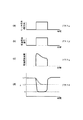
リッチスパイクは、触媒過昇温防止及び燃費悪化防止の観点からエンジン側の吸気量制御によりエンジンから出たガスの空気過剰率(以下、「エンジンλ」と称する)も合せて低下させて行うのが一般的である。図3のグラフα〜グラフδは触媒再生のタイミング及び各値の変化を示す説明図である。図3に示すように、触媒に再生動作が必要になったことが判定されると、再生動作開始信号が発生し、リッチ信号(エンジン燃焼制御信号)が発生する(グラフα)。これにより、EGRや吸気スロットルを絞る等の方法でエンジンλの低下が開始される。同時に軽油添加信号が発生し(グラフβ)、軽油が添加される。グラフγは軽油添加流量を示している。このような動作により、通常運転時には触媒前λが1.7〜10であったものを1程度まで低下する(グラフδ)。なお、EGRや吸気スロットルを絞る等の吸気系のみの動作でエンジンλを低下させる場合に、トルクショックの回避や黒煙悪化を回避しようとするとグラフδ中点線で示すように、触媒前λは1.3程度までしか低下せず、十分なリッチスパイクができない。
上述した排ガス浄化装置であると次のような問題があった。すなわち、エンジンλの低下と、軽油添加とを同時に行った場合、吸気系の応答遅れのためにエンジンλが十分に低下しないうちに、軽油の添加が開始されることになり、軽油の添加量が増え、燃費が悪化するという問題があった。また、軽油の添加量が増大して触媒が過昇温するという問題もあった。 The exhaust gas purification device described above has the following problems. That is, when the decrease in engine λ and the addition of light oil are performed at the same time, the addition of light oil is started before the engine λ is sufficiently decreased due to a delay in response of the intake system. There was a problem that the fuel consumption was worsened. There is also a problem that the amount of light oil added increases and the catalyst overheats.
そこで本発明は、リッチスパイク時の軽油添加量を最小限に抑えるとともに、触媒の過昇温を防止できるエンジンの排ガス浄化装置を提供することを目的としている。 Accordingly, an object of the present invention is to provide an exhaust gas purifying apparatus for an engine that can minimize the amount of light oil added at the time of a rich spike and prevent an excessive temperature rise of a catalyst.
上記課題を解決し目的を達成するために、本発明のエンジンの排ガス浄化装置は次のように構成されている。 In order to solve the above problems and achieve the object, the engine exhaust gas purification apparatus of the present invention is configured as follows.
(1)エンジンの排気通路に設けられ、前記排気通路に流入する排ガス中のNOxを吸蔵し、かつ、前記排ガスの空燃比が低下したときに再生処理される触媒と、前記触媒より排気上流側の排気通路に設けられ、通路内の空燃比を計測する空燃比センサと、前記触媒より排気上流側の排気通路に設けられ、通路内に軽油を噴射可能な軽油添加部と、前記触媒の再生開始時期を判定する再生開始時期判定手段と、この再生開始判定手段の判定結果に基づいて、前記排気通路内の空燃比を第1の値まで低下させるようにエンジンの燃焼を制御する制御部とを備え、前記制御部は、前記排気通路内の空燃比が前記第1の値に達した時点で前記排気通路内の空燃比をさらに第2の値まで低下させるように前記軽油添加部により軽油を噴射させることを特徴とする。 (1) A catalyst that is provided in an exhaust passage of the engine, stores NOx in exhaust gas flowing into the exhaust passage, and is regenerated when the air-fuel ratio of the exhaust gas decreases, and an exhaust upstream side of the catalyst An air-fuel ratio sensor that measures the air-fuel ratio in the passage, a light oil addition portion that is provided in an exhaust passage upstream of the catalyst and that can inject light oil into the passage, and regeneration of the catalyst A regeneration start timing determining means for determining a start timing; and a control unit for controlling combustion of the engine so as to lower the air-fuel ratio in the exhaust passage to a first value based on a determination result of the regeneration start determining means; And the control unit uses the light oil addition unit to reduce the air oil ratio in the exhaust passage to a second value when the air fuel ratio in the exhaust passage reaches the first value. To inject And butterflies.
(2)エンジンの排気通路に設けられ、前記排気通路に流入する排ガス中のNOxを吸蔵し、かつ、前記排ガスの空燃比が低下したときに再生処理される触媒と、前記触媒より排気上流側の排気通路に設けられ、通路内の空燃比を計測する空燃比センサと、前記触媒より排気上流側の排気通路に設けられ、通路内に軽油を噴射可能な軽油添加部と、前記触媒の再生開始時期を判定する再生開始判定手段と、この再生開始判定手段の判定結果に基づいて、前記排気通路内の空燃比を低下させるようにエンジンの燃焼を制御する制御部とを備え、前記制御部は、前記排気通路内の空燃比をエンジンの燃焼制御により低下させ始めてから所定時間経過後に前記排気通路内の空燃比を所定の値まで低下させるように前記軽油添加部における前記軽油の噴射させることを特徴とする。 (2) a catalyst that is provided in the exhaust passage of the engine, stores NOx in the exhaust gas flowing into the exhaust passage, and is regenerated when the air-fuel ratio of the exhaust gas decreases, and an exhaust upstream side of the catalyst An air-fuel ratio sensor that measures the air-fuel ratio in the passage, a light oil addition portion that is provided in an exhaust passage upstream of the catalyst and that can inject light oil into the passage, and regeneration of the catalyst A regeneration start determining means for determining a start time; and a control unit for controlling combustion of the engine so as to lower an air-fuel ratio in the exhaust passage based on a determination result of the regeneration start determining means, The air-fuel ratio in the light oil adding section is reduced so that the air-fuel ratio in the exhaust passage is lowered to a predetermined value after a lapse of a predetermined time from the start of lowering the air-fuel ratio in the exhaust passage by engine combustion control. And characterized in that Isa.
本発明によれば、リッチスパイク時の軽油添加量を最小限に抑えるとともに、触媒の過昇温の防止が可能となる。 According to the present invention, it is possible to minimize the amount of light oil added at the time of rich spike and to prevent the catalyst from being overheated.
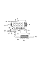
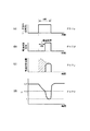
図1は本発明の一実施の形態に係るエンジンシステム10の構成を示す説明図、図2のグラフα〜グラフδはエンジンシステム10における触媒再生のタイミング及び各値の変化を示す説明図である。グラフαは再生動作を示すリッチ信号(エンジンの燃焼制御のリッチ信号)、グラフβは軽油添加信号、グラフγは軽油添加流量、グラフδは触媒前λを示している。
FIG. 1 is an explanatory diagram showing a configuration of an
エンジンシステム10は、ディーゼルエンジン20を備えている。ディーゼルエンジン20の入口側には吸気配管30が接続され、出口側には排気配管40が接続されている。さらにディーゼルエンジン20の排気側と吸気配管30とは、排ガス(EGRガス)を吸気配管30に還流するEGR配管50とで接続されている。なお、図1中60は過給機、100は各部を連携制御する制御部を示している。
The
吸気配管30には、吸気側からエアフローセンサ31、過給機60のコンプレッサ61と、インタークーラ32と、吸気スロットル33と、EGR配管50との接続部34とが設けられている。
The
排気配管40には、ディーゼルエンジン20側から、過給機60のタービン62と、排気配管40内の空燃比を計測するλセンサ41と、排気軽油添加インジェクタ42と、NOx吸蔵触媒43とが設けられている。
From the
NOx吸蔵触媒43は排気配管40に流入する排ガス中のNOxを吸蔵し、かつ、排ガスの空燃比を低下させたときに吸蔵したNOxを再生処理する。
The
EGR配管50には、排気配管40側から排気ガスを冷却するEGRクーラ51と、排ガスの流量を調節するEGRバルブ52とが設けられている。
The EGR
制御部100の制御入力部には、エンジン回転速度、アクセル開度信号、エアフローセンサ31、λセンサ41の出力等が入力され、制御出力部には、吸気スロットル33、EGRバルブ52、排気軽油添加インジェクタ42が接続されている。なお、図1中101は再生開始判定手段であり、再生開始判定手段101は再生開始のタイミングを決めるタイマの機能を有している。
The engine input speed, the accelerator opening signal, the output of the
このように構成されたエンジンシステム10では、次のような動作でリッチスパイクを行い、NOx吸蔵触媒43を再生させる。すなわち、通常のエンジン動作が行われている状況下で、再生開始タイミングが再生開始判定手段101により判定される。再生開始タイミングは、一定時間(例えば1分)の経過として設定されている。
In the
再生開始判定手段101からの判定信号により、リッチスパイクが開始されると図2のグラフαに示すように、最初にエンジンλの低下が開始される。具体的にはエンジンの吸気スロットル33の開度を絞ったり、EGRを増大させて燃料を制御することによりエンジンλの低下が行われる。この時間は例えば4秒間である。グラフδに示すように、低下開始から約2秒間で、触媒前λが1.7であったものが1.3まで低下してゆく。なお、ここでのλ=1.3はエンジンの燃焼制御における目標値であり、排気エミッションの急激な悪化を伴うこと無く制御可能なλとして設定される。リッチスパイク開始から2秒経過後に排気軽油添加インジェクタ42から軽油が噴射される(グラフβ)。この時間は例えば2秒間である。グラフγは軽油添加流量を示している。
When the rich spike is started by the determination signal from the reproduction
すなわち、触媒前λが1.3に達した時点で排気軽油添加インジェクタ42から軽油が噴射されることになるので短時間で目標の触媒前λが1に達することとなり、NOx吸蔵触媒43が再生される。なお、グラフδ中点線は排気軽油添加インジェクタ42から軽油が噴射されなかった場合の触媒前λの変化を示している。
That is, when the pre-catalyst λ reaches 1.3, the light oil is injected from the exhaust gas
リッチスパイクの開始から4秒後に、EGRバルブ52、吸気スロットル33が定常時の位置に戻るとともに、排気軽油添加インジェクタ42からの軽油の噴射が停止し、リッチスパイク動作が終了する。これにより、触媒前λが1.7に戻り、通常のエンジン動作が行われることとなる。
After 4 seconds from the start of the rich spike, the
その結果、図2のグラフλにおいて、破線で示されたエンジンλの低下と軽油添加を同時に行った場合の軽油添加量に対して、斜線で示された領域分の添加量を低減することができるのである。 As a result, in the graph λ of FIG. 2, the addition amount of the region indicated by the oblique line can be reduced with respect to the addition amount of the light oil when the decrease in the engine λ indicated by the broken line and the addition of the light oil are performed simultaneously. It can be done.
上述したように、本実施の形態に係るエンジンシステム10においては、エンジンλが十分に低下した状態で、排気軽油添加インジェクタ42からの軽油の噴射を開始するようにしているので、軽油の添加流量を減らすことができ、燃費の悪化を防止できるとともに、NOx吸蔵触媒43に過剰な軽油が添加されないため、NOx吸蔵触媒43の過昇温を防止することができる。
As described above, in the
なお、上述した再生開始タイミングとして、一定時間の経過としたが、再生開始時期判定手段により排気ガスの積算流量やNOx吸蔵触媒43の吸蔵量等を算出して、一定量に達した時点を再生開始タイミングとしてもよい。
Although the regeneration start timing described above has passed for a certain period of time, the regeneration start timing determination means calculates the accumulated flow rate of exhaust gas, the storage amount of the
さらに、再生開始タイミングから一定の遅延時間経過後に排気軽油添加インジェクタ42からの軽油の噴射を開始するようにしているが、λセンサ41による排気配管40内の空燃比の実測値が例えば1.3に達した時点で排気軽油添加インジェクタ42からの軽油の噴射を開始するようにしてもよい。また、λセンサ41による排気配管40内の空燃比の実測値ではなく、エアフローセンサ31によって計測される吸入空気重量とディーゼルエンジン20の噴射系ECUの噴射量指示値とによる計算値を用いるようにしても良い。
Further, the injection of the light oil from the exhaust gas
この他、エンジンλの低下方法としては、上記の吸気絞りやEGRの増大に加えてディーゼルエンジン20におけるポスト燃料噴射により調整する方法を用いても良い。
In addition, as a method for lowering the engine λ, a method of adjusting by post fuel injection in the
なお、本発明は前記実施の形態に限定されるものではなく、本発明の要旨を逸脱しない範囲で種々変形実施可能であるのは勿論である。 Note that the present invention is not limited to the above-described embodiment, and various modifications can be made without departing from the scope of the present invention.
10…エンジンシステム、20…ディーゼルエンジン、30…吸気配管、33…吸気スロットル、40…排気配管、41…λセンサ、42…排気軽油添加インジェクタ、50…EGR配管、60…過給機、100…制御部、101…再生開始時期判定手段。
DESCRIPTION OF
Claims (2)
前記触媒より排気上流側の排気通路に設けられ、通路内の空燃比を計測する空燃比センサと、
前記触媒より排気上流側の排気通路に設けられ、通路内に軽油を噴射可能な軽油添加部と、
前記触媒の再生開始時期を判定する再生開始時期判定手段と、
この再生開始判定手段の判定結果に基づいて、前記排気通路内の空燃比を第1の値まで低下させるようにエンジンの燃焼を制御する制御部とを備え、
前記制御部は、前記排気通路内の空燃比が前記第1の値に達した時点で前記排気通路内の空燃比をさらに第2の値まで低下させるように前記軽油添加部により軽油を噴射させることを特徴とするエンジンの排ガス浄化装置。 A catalyst provided in the exhaust passage of the engine, storing NOx in the exhaust gas flowing into the exhaust passage, and being regenerated when the air-fuel ratio of the exhaust gas decreases;
An air-fuel ratio sensor provided in an exhaust passage upstream of the catalyst and measuring an air-fuel ratio in the passage;
A light oil addition section provided in an exhaust passage upstream of the catalyst and capable of injecting light oil into the passage;
Regeneration start time determining means for determining the catalyst regeneration start time;
A control unit that controls combustion of the engine so as to lower the air-fuel ratio in the exhaust passage to a first value based on a determination result of the regeneration start determination unit;
The control unit causes the light oil addition unit to inject light oil so that the air-fuel ratio in the exhaust passage further decreases to a second value when the air-fuel ratio in the exhaust passage reaches the first value. An exhaust gas purification device for an engine characterized by the above.
前記触媒より排気上流側の排気通路に設けられ、通路内の空燃比を計測する空燃比センサと、
前記触媒より排気上流側の排気通路に設けられ、通路内に軽油を噴射可能な軽油添加部と、
前記触媒の再生開始時期を判定する再生開始判定手段と、
この再生開始判定手段の判定結果に基づいて、前記排気通路内の空燃比を低下させるようにエンジンの燃焼を制御する制御部とを備え、
前記制御部は、前記排気通路内の空燃比をエンジンの燃焼制御により低下させ始めてから所定時間経過後に前記排気通路内の空燃比を所定の値まで低下させるように前記軽油添加部における前記軽油の噴射させることを特徴とするエンジンの排ガス浄化装置。 A catalyst provided in the exhaust passage of the engine, storing NOx in the exhaust gas flowing into the exhaust passage, and being regenerated when the air-fuel ratio of the exhaust gas decreases;
An air-fuel ratio sensor provided in an exhaust passage upstream of the catalyst and measuring an air-fuel ratio in the passage;
A light oil addition section provided in an exhaust passage upstream of the catalyst and capable of injecting light oil into the passage;
Regeneration start determining means for determining the regeneration start time of the catalyst;
A controller for controlling combustion of the engine so as to lower the air-fuel ratio in the exhaust passage based on the determination result of the regeneration start determining means;
The control unit is configured to reduce the air-fuel ratio in the light oil addition unit so as to decrease the air-fuel ratio in the exhaust passage to a predetermined value after a lapse of a predetermined time from the start of reducing the air-fuel ratio in the exhaust passage by engine combustion control. An exhaust gas purification apparatus for an engine characterized by being injected.
Priority Applications (1)
| Application Number | Priority Date | Filing Date | Title |
|---|---|---|---|
| JP2004107534A JP2005291095A (en) | 2004-03-31 | 2004-03-31 | Exhaust emission control device for engine |
Applications Claiming Priority (1)
| Application Number | Priority Date | Filing Date | Title |
|---|---|---|---|
| JP2004107534A JP2005291095A (en) | 2004-03-31 | 2004-03-31 | Exhaust emission control device for engine |
Publications (1)
| Publication Number | Publication Date |
|---|---|
| JP2005291095A true JP2005291095A (en) | 2005-10-20 |
Family
ID=35324308
Family Applications (1)
| Application Number | Title | Priority Date | Filing Date |
|---|---|---|---|
| JP2004107534A Pending JP2005291095A (en) | 2004-03-31 | 2004-03-31 | Exhaust emission control device for engine |
Country Status (1)
| Country | Link |
|---|---|
| JP (1) | JP2005291095A (en) |
Cited By (2)
| Publication number | Priority date | Publication date | Assignee | Title |
|---|---|---|---|---|
| JP2007126991A (en) * | 2005-11-01 | 2007-05-24 | Toyota Motor Corp | Exhaust gas purification system for internal combustion engine |
| WO2008105544A1 (en) * | 2007-02-23 | 2008-09-04 | Toyota Jidosha Kabushiki Kaisha | Exhaust purification system for internal combustion engine |
-
2004
- 2004-03-31 JP JP2004107534A patent/JP2005291095A/en active Pending
Cited By (5)
| Publication number | Priority date | Publication date | Assignee | Title |
|---|---|---|---|---|
| JP2007126991A (en) * | 2005-11-01 | 2007-05-24 | Toyota Motor Corp | Exhaust gas purification system for internal combustion engine |
| WO2008105544A1 (en) * | 2007-02-23 | 2008-09-04 | Toyota Jidosha Kabushiki Kaisha | Exhaust purification system for internal combustion engine |
| JP2008208724A (en) * | 2007-02-23 | 2008-09-11 | Toyota Motor Corp | Exhaust gas purification system for internal combustion engine |
| US8272209B2 (en) | 2007-02-23 | 2012-09-25 | Toyota Jidosha Kabushiki Kaisha | Exhaust gas purification system for internal combustion engine |
| EP2119896A4 (en) * | 2007-02-23 | 2015-05-27 | Toyota Motor Co Ltd | EXHAUST GAS CLEANING SYSTEM FOR INTERNAL COMBUSTION ENGINE |
Similar Documents
| Publication | Publication Date | Title |
|---|---|---|
| US8266898B2 (en) | Control apparatus for internal combustion engine | |
| US20100132334A1 (en) | Method and device for monitoring the regeneration of a pollution-removal system | |
| US8261535B2 (en) | Enhanced post injection control system for diesel particulate filters | |
| US7993582B2 (en) | Sulfur purge control device for an internal combustion engine | |
| US6792751B2 (en) | Exhaust gas purification device and method for diesel engine | |
| JP2004293339A (en) | Exhaust emission control device | |
| JP5311082B2 (en) | Operation method of diesel engine equipped with exhaust gas purification device having nitrogen oxide storage catalyst | |
| JP2005291100A (en) | Exhaust emission control device for engine | |
| JP6268684B2 (en) | Engine exhaust purification system | |
| JP2002129945A (en) | Exhaust gas purification device for internal combustion engine | |
| JP4244562B2 (en) | Exhaust gas purification device for internal combustion engine | |
| US7594390B2 (en) | Combustion control apparatus and method for internal combustion engine | |
| WO2011048706A1 (en) | Air/fuel ratio control device for internal combustion engine | |
| JP6230006B1 (en) | Engine exhaust purification system | |
| US9347359B2 (en) | Air dithering for internal combustion engine system | |
| JP2002161733A (en) | Exhaust gas purification device for internal combustion engine | |
| JP4247616B2 (en) | Fuel injection control device for diesel engine | |
| JP6230007B1 (en) | Engine exhaust purification system | |
| JP4063743B2 (en) | Fuel injection timing control device for internal combustion engine | |
| JP2019132165A (en) | Exhaust emission control device for engine | |
| JP4404841B2 (en) | Control device for internal combustion engine | |
| WO2009008395A1 (en) | Exhaust purification device for internal combustion engine | |
| JP4433945B2 (en) | Exhaust gas purification system for internal combustion engine | |
| JP3855817B2 (en) | Control device for internal combustion engine | |
| JP2018009486A (en) | Engine exhaust purification system |
Legal Events
| Date | Code | Title | Description |
|---|---|---|---|
| A621 | Written request for application examination |
Free format text: JAPANESE INTERMEDIATE CODE: A621 Effective date: 20070112 |
|
| A977 | Report on retrieval |
Free format text: JAPANESE INTERMEDIATE CODE: A971007 Effective date: 20090831 |
|
| A131 | Notification of reasons for refusal |
Free format text: JAPANESE INTERMEDIATE CODE: A131 Effective date: 20090901 |
|
| A02 | Decision of refusal |
Free format text: JAPANESE INTERMEDIATE CODE: A02 Effective date: 20100105 |