JP2005291100A - Exhaust emission control device for engine - Google Patents
Exhaust emission control device for engine Download PDFInfo
- Publication number
- JP2005291100A JP2005291100A JP2004107807A JP2004107807A JP2005291100A JP 2005291100 A JP2005291100 A JP 2005291100A JP 2004107807 A JP2004107807 A JP 2004107807A JP 2004107807 A JP2004107807 A JP 2004107807A JP 2005291100 A JP2005291100 A JP 2005291100A
- Authority
- JP
- Japan
- Prior art keywords
- catalyst
- temperature
- rich spike
- engine
- purge
- Prior art date
- Legal status (The legal status is an assumption and is not a legal conclusion. Google has not performed a legal analysis and makes no representation as to the accuracy of the status listed.)
- Withdrawn
Links
Images


Classifications
-
- F—MECHANICAL ENGINEERING; LIGHTING; HEATING; WEAPONS; BLASTING
- F01—MACHINES OR ENGINES IN GENERAL; ENGINE PLANTS IN GENERAL; STEAM ENGINES
- F01N—GAS-FLOW SILENCERS OR EXHAUST APPARATUS FOR MACHINES OR ENGINES IN GENERAL; GAS-FLOW SILENCERS OR EXHAUST APPARATUS FOR INTERNAL-COMBUSTION ENGINES
- F01N9/00—Electrical control of exhaust gas treating apparatus
-
- F—MECHANICAL ENGINEERING; LIGHTING; HEATING; WEAPONS; BLASTING
- F01—MACHINES OR ENGINES IN GENERAL; ENGINE PLANTS IN GENERAL; STEAM ENGINES
- F01N—GAS-FLOW SILENCERS OR EXHAUST APPARATUS FOR MACHINES OR ENGINES IN GENERAL; GAS-FLOW SILENCERS OR EXHAUST APPARATUS FOR INTERNAL-COMBUSTION ENGINES
- F01N3/00—Exhaust or silencing apparatus having means for purifying, rendering innocuous, or otherwise treating exhaust
- F01N3/08—Exhaust or silencing apparatus having means for purifying, rendering innocuous, or otherwise treating exhaust for rendering innocuous
- F01N3/0807—Exhaust or silencing apparatus having means for purifying, rendering innocuous, or otherwise treating exhaust for rendering innocuous by using absorbents or adsorbents
- F01N3/0871—Exhaust or silencing apparatus having means for purifying, rendering innocuous, or otherwise treating exhaust for rendering innocuous by using absorbents or adsorbents using means for controlling, e.g. purging, the absorbents or adsorbents
-
- F—MECHANICAL ENGINEERING; LIGHTING; HEATING; WEAPONS; BLASTING
- F01—MACHINES OR ENGINES IN GENERAL; ENGINE PLANTS IN GENERAL; STEAM ENGINES
- F01N—GAS-FLOW SILENCERS OR EXHAUST APPARATUS FOR MACHINES OR ENGINES IN GENERAL; GAS-FLOW SILENCERS OR EXHAUST APPARATUS FOR INTERNAL-COMBUSTION ENGINES
- F01N3/00—Exhaust or silencing apparatus having means for purifying, rendering innocuous, or otherwise treating exhaust
- F01N3/08—Exhaust or silencing apparatus having means for purifying, rendering innocuous, or otherwise treating exhaust for rendering innocuous
- F01N3/0807—Exhaust or silencing apparatus having means for purifying, rendering innocuous, or otherwise treating exhaust for rendering innocuous by using absorbents or adsorbents
- F01N3/0828—Exhaust or silencing apparatus having means for purifying, rendering innocuous, or otherwise treating exhaust for rendering innocuous by using absorbents or adsorbents characterised by the absorbed or adsorbed substances
- F01N3/0842—Nitrogen oxides
-
- F—MECHANICAL ENGINEERING; LIGHTING; HEATING; WEAPONS; BLASTING
- F01—MACHINES OR ENGINES IN GENERAL; ENGINE PLANTS IN GENERAL; STEAM ENGINES
- F01N—GAS-FLOW SILENCERS OR EXHAUST APPARATUS FOR MACHINES OR ENGINES IN GENERAL; GAS-FLOW SILENCERS OR EXHAUST APPARATUS FOR INTERNAL-COMBUSTION ENGINES
- F01N3/00—Exhaust or silencing apparatus having means for purifying, rendering innocuous, or otherwise treating exhaust
- F01N3/08—Exhaust or silencing apparatus having means for purifying, rendering innocuous, or otherwise treating exhaust for rendering innocuous
- F01N3/0807—Exhaust or silencing apparatus having means for purifying, rendering innocuous, or otherwise treating exhaust for rendering innocuous by using absorbents or adsorbents
- F01N3/0871—Exhaust or silencing apparatus having means for purifying, rendering innocuous, or otherwise treating exhaust for rendering innocuous by using absorbents or adsorbents using means for controlling, e.g. purging, the absorbents or adsorbents
- F01N3/0885—Regeneration of deteriorated absorbents or adsorbents, e.g. desulfurization of NOx traps
-
- F—MECHANICAL ENGINEERING; LIGHTING; HEATING; WEAPONS; BLASTING
- F02—COMBUSTION ENGINES; HOT-GAS OR COMBUSTION-PRODUCT ENGINE PLANTS
- F02D—CONTROLLING COMBUSTION ENGINES
- F02D41/00—Electrical control of supply of combustible mixture or its constituents
- F02D41/02—Circuit arrangements for generating control signals
- F02D41/021—Introducing corrections for particular conditions exterior to the engine
- F02D41/0235—Introducing corrections for particular conditions exterior to the engine in relation with the state of the exhaust gas treating apparatus
- F02D41/024—Introducing corrections for particular conditions exterior to the engine in relation with the state of the exhaust gas treating apparatus to increase temperature of the exhaust gas treating apparatus
- F02D41/025—Introducing corrections for particular conditions exterior to the engine in relation with the state of the exhaust gas treating apparatus to increase temperature of the exhaust gas treating apparatus by changing the composition of the exhaust gas, e.g. for exothermic reaction on exhaust gas treating apparatus
-
- F—MECHANICAL ENGINEERING; LIGHTING; HEATING; WEAPONS; BLASTING
- F02—COMBUSTION ENGINES; HOT-GAS OR COMBUSTION-PRODUCT ENGINE PLANTS
- F02D—CONTROLLING COMBUSTION ENGINES
- F02D41/00—Electrical control of supply of combustible mixture or its constituents
- F02D41/02—Circuit arrangements for generating control signals
- F02D41/021—Introducing corrections for particular conditions exterior to the engine
- F02D41/0235—Introducing corrections for particular conditions exterior to the engine in relation with the state of the exhaust gas treating apparatus
- F02D41/027—Introducing corrections for particular conditions exterior to the engine in relation with the state of the exhaust gas treating apparatus to purge or regenerate the exhaust gas treating apparatus
- F02D41/0275—Introducing corrections for particular conditions exterior to the engine in relation with the state of the exhaust gas treating apparatus to purge or regenerate the exhaust gas treating apparatus the exhaust gas treating apparatus being a NOx trap or adsorbent
- F02D41/028—Desulfurisation of NOx traps or adsorbent
-
- F—MECHANICAL ENGINEERING; LIGHTING; HEATING; WEAPONS; BLASTING
- F02—COMBUSTION ENGINES; HOT-GAS OR COMBUSTION-PRODUCT ENGINE PLANTS
- F02D—CONTROLLING COMBUSTION ENGINES
- F02D41/00—Electrical control of supply of combustible mixture or its constituents
- F02D41/02—Circuit arrangements for generating control signals
- F02D41/04—Introducing corrections for particular operating conditions
-
- F—MECHANICAL ENGINEERING; LIGHTING; HEATING; WEAPONS; BLASTING
- F01—MACHINES OR ENGINES IN GENERAL; ENGINE PLANTS IN GENERAL; STEAM ENGINES
- F01N—GAS-FLOW SILENCERS OR EXHAUST APPARATUS FOR MACHINES OR ENGINES IN GENERAL; GAS-FLOW SILENCERS OR EXHAUST APPARATUS FOR INTERNAL-COMBUSTION ENGINES
- F01N2430/00—Influencing exhaust purification, e.g. starting of catalytic reaction, filter regeneration, or the like, by controlling engine operating characteristics
- F01N2430/06—Influencing exhaust purification, e.g. starting of catalytic reaction, filter regeneration, or the like, by controlling engine operating characteristics by varying fuel-air ratio, e.g. by enriching fuel-air mixture
-
- F—MECHANICAL ENGINEERING; LIGHTING; HEATING; WEAPONS; BLASTING
- F01—MACHINES OR ENGINES IN GENERAL; ENGINE PLANTS IN GENERAL; STEAM ENGINES
- F01N—GAS-FLOW SILENCERS OR EXHAUST APPARATUS FOR MACHINES OR ENGINES IN GENERAL; GAS-FLOW SILENCERS OR EXHAUST APPARATUS FOR INTERNAL-COMBUSTION ENGINES
- F01N2570/00—Exhaust treating apparatus eliminating, absorbing or adsorbing specific elements or compounds
- F01N2570/04—Sulfur or sulfur oxides
-
- F—MECHANICAL ENGINEERING; LIGHTING; HEATING; WEAPONS; BLASTING
- F01—MACHINES OR ENGINES IN GENERAL; ENGINE PLANTS IN GENERAL; STEAM ENGINES
- F01N—GAS-FLOW SILENCERS OR EXHAUST APPARATUS FOR MACHINES OR ENGINES IN GENERAL; GAS-FLOW SILENCERS OR EXHAUST APPARATUS FOR INTERNAL-COMBUSTION ENGINES
- F01N2570/00—Exhaust treating apparatus eliminating, absorbing or adsorbing specific elements or compounds
- F01N2570/14—Nitrogen oxides
-
- F—MECHANICAL ENGINEERING; LIGHTING; HEATING; WEAPONS; BLASTING
- F01—MACHINES OR ENGINES IN GENERAL; ENGINE PLANTS IN GENERAL; STEAM ENGINES
- F01N—GAS-FLOW SILENCERS OR EXHAUST APPARATUS FOR MACHINES OR ENGINES IN GENERAL; GAS-FLOW SILENCERS OR EXHAUST APPARATUS FOR INTERNAL-COMBUSTION ENGINES
- F01N3/00—Exhaust or silencing apparatus having means for purifying, rendering innocuous, or otherwise treating exhaust
- F01N3/08—Exhaust or silencing apparatus having means for purifying, rendering innocuous, or otherwise treating exhaust for rendering innocuous
- F01N3/0807—Exhaust or silencing apparatus having means for purifying, rendering innocuous, or otherwise treating exhaust for rendering innocuous by using absorbents or adsorbents
- F01N3/0814—Exhaust or silencing apparatus having means for purifying, rendering innocuous, or otherwise treating exhaust for rendering innocuous by using absorbents or adsorbents combined with catalytic converters, e.g. NOx absorption/storage reduction catalysts
-
- F—MECHANICAL ENGINEERING; LIGHTING; HEATING; WEAPONS; BLASTING
- F01—MACHINES OR ENGINES IN GENERAL; ENGINE PLANTS IN GENERAL; STEAM ENGINES
- F01N—GAS-FLOW SILENCERS OR EXHAUST APPARATUS FOR MACHINES OR ENGINES IN GENERAL; GAS-FLOW SILENCERS OR EXHAUST APPARATUS FOR INTERNAL-COMBUSTION ENGINES
- F01N3/00—Exhaust or silencing apparatus having means for purifying, rendering innocuous, or otherwise treating exhaust
- F01N3/08—Exhaust or silencing apparatus having means for purifying, rendering innocuous, or otherwise treating exhaust for rendering innocuous
- F01N3/10—Exhaust or silencing apparatus having means for purifying, rendering innocuous, or otherwise treating exhaust for rendering innocuous by thermal or catalytic conversion of noxious components of exhaust
- F01N3/24—Exhaust or silencing apparatus having means for purifying, rendering innocuous, or otherwise treating exhaust for rendering innocuous by thermal or catalytic conversion of noxious components of exhaust characterised by constructional aspects of converting apparatus
- F01N3/36—Arrangements for supply of additional fuel
-
- F—MECHANICAL ENGINEERING; LIGHTING; HEATING; WEAPONS; BLASTING
- F02—COMBUSTION ENGINES; HOT-GAS OR COMBUSTION-PRODUCT ENGINE PLANTS
- F02B—INTERNAL-COMBUSTION PISTON ENGINES; COMBUSTION ENGINES IN GENERAL
- F02B29/00—Engines characterised by provision for charging or scavenging not provided for in groups F02B25/00, F02B27/00 or F02B33/00 - F02B39/00; Details thereof
- F02B29/04—Cooling of air intake supply
- F02B29/0406—Layout of the intake air cooling or coolant circuit
-
- F—MECHANICAL ENGINEERING; LIGHTING; HEATING; WEAPONS; BLASTING
- F02—COMBUSTION ENGINES; HOT-GAS OR COMBUSTION-PRODUCT ENGINE PLANTS
- F02B—INTERNAL-COMBUSTION PISTON ENGINES; COMBUSTION ENGINES IN GENERAL
- F02B37/00—Engines characterised by provision of pumps driven at least for part of the time by exhaust
-
- F—MECHANICAL ENGINEERING; LIGHTING; HEATING; WEAPONS; BLASTING
- F02—COMBUSTION ENGINES; HOT-GAS OR COMBUSTION-PRODUCT ENGINE PLANTS
- F02D—CONTROLLING COMBUSTION ENGINES
- F02D2200/00—Input parameters for engine control
- F02D2200/02—Input parameters for engine control the parameters being related to the engine
- F02D2200/08—Exhaust gas treatment apparatus parameters
- F02D2200/0802—Temperature of the exhaust gas treatment apparatus
-
- F—MECHANICAL ENGINEERING; LIGHTING; HEATING; WEAPONS; BLASTING
- F02—COMBUSTION ENGINES; HOT-GAS OR COMBUSTION-PRODUCT ENGINE PLANTS
- F02M—SUPPLYING COMBUSTION ENGINES IN GENERAL WITH COMBUSTIBLE MIXTURES OR CONSTITUENTS THEREOF
- F02M26/00—Engine-pertinent apparatus for adding exhaust gases to combustion-air, main fuel or fuel-air mixture, e.g. by exhaust gas recirculation [EGR] systems
- F02M26/02—EGR systems specially adapted for supercharged engines
- F02M26/04—EGR systems specially adapted for supercharged engines with a single turbocharger
- F02M26/05—High pressure loops, i.e. wherein recirculated exhaust gas is taken out from the exhaust system upstream of the turbine and reintroduced into the intake system downstream of the compressor
-
- F—MECHANICAL ENGINEERING; LIGHTING; HEATING; WEAPONS; BLASTING
- F02—COMBUSTION ENGINES; HOT-GAS OR COMBUSTION-PRODUCT ENGINE PLANTS
- F02M—SUPPLYING COMBUSTION ENGINES IN GENERAL WITH COMBUSTIBLE MIXTURES OR CONSTITUENTS THEREOF
- F02M26/00—Engine-pertinent apparatus for adding exhaust gases to combustion-air, main fuel or fuel-air mixture, e.g. by exhaust gas recirculation [EGR] systems
- F02M26/13—Arrangement or layout of EGR passages, e.g. in relation to specific engine parts or for incorporation of accessories
- F02M26/22—Arrangement or layout of EGR passages, e.g. in relation to specific engine parts or for incorporation of accessories with coolers in the recirculation passage
- F02M26/23—Layout, e.g. schematics
-
- Y—GENERAL TAGGING OF NEW TECHNOLOGICAL DEVELOPMENTS; GENERAL TAGGING OF CROSS-SECTIONAL TECHNOLOGIES SPANNING OVER SEVERAL SECTIONS OF THE IPC; TECHNICAL SUBJECTS COVERED BY FORMER USPC CROSS-REFERENCE ART COLLECTIONS [XRACs] AND DIGESTS
- Y02—TECHNOLOGIES OR APPLICATIONS FOR MITIGATION OR ADAPTATION AGAINST CLIMATE CHANGE
- Y02A—TECHNOLOGIES FOR ADAPTATION TO CLIMATE CHANGE
- Y02A50/00—TECHNOLOGIES FOR ADAPTATION TO CLIMATE CHANGE in human health protection, e.g. against extreme weather
- Y02A50/20—Air quality improvement or preservation, e.g. vehicle emission control or emission reduction by using catalytic converters
-
- Y—GENERAL TAGGING OF NEW TECHNOLOGICAL DEVELOPMENTS; GENERAL TAGGING OF CROSS-SECTIONAL TECHNOLOGIES SPANNING OVER SEVERAL SECTIONS OF THE IPC; TECHNICAL SUBJECTS COVERED BY FORMER USPC CROSS-REFERENCE ART COLLECTIONS [XRACs] AND DIGESTS
- Y02—TECHNOLOGIES OR APPLICATIONS FOR MITIGATION OR ADAPTATION AGAINST CLIMATE CHANGE
- Y02T—CLIMATE CHANGE MITIGATION TECHNOLOGIES RELATED TO TRANSPORTATION
- Y02T10/00—Road transport of goods or passengers
- Y02T10/10—Internal combustion engine [ICE] based vehicles
- Y02T10/12—Improving ICE efficiencies
Landscapes
- Engineering & Computer Science (AREA)
- Chemical & Material Sciences (AREA)
- Combustion & Propulsion (AREA)
- Mechanical Engineering (AREA)
- General Engineering & Computer Science (AREA)
- Exhaust Gas After Treatment (AREA)
- Electrical Control Of Air Or Fuel Supplied To Internal-Combustion Engine (AREA)
- Combined Controls Of Internal Combustion Engines (AREA)
Abstract
Description
本発明は、内燃機関の排気に含まれる有害成分を浄化する排気浄化機能を備えたエンジンの排ガス浄化装置に関し、特にSパージ運転時の触媒昇温制御に関する。 The present invention relates to an exhaust gas purification apparatus for an engine having an exhaust gas purification function for purifying harmful components contained in exhaust gas of an internal combustion engine, and more particularly to catalyst temperature increase control during an S purge operation.
従来、エンジンの排気管にNOx吸蔵触媒が設けられた排ガス浄化装置が知られている。このようなNOx触媒を用いた排ガス浄化装置は、吸蔵したNOxを放出・還元するためにNOx還元触媒の排気上流側に軽油等の還元剤を供給することにより触媒に入るガスの空気過剰率(以下、「触媒前λ」と称する)を1以下に低下させるリッチスパイクを定期的(例えば1分に1回)に行う必要がある。具体的には、エンジンの吸気系の制御やポスト噴射等によりλを低下させると共に触媒上流の排気管に燃料を噴射してリッチスパイクが行われる。 2. Description of the Related Art Conventionally, an exhaust gas purification device in which an NOx storage catalyst is provided in an engine exhaust pipe is known. In such an exhaust gas purification apparatus using a NOx catalyst, an excess air ratio of gas entering the catalyst by supplying a reducing agent such as light oil to the exhaust upstream side of the NOx reduction catalyst in order to release and reduce the stored NOx ( Hereinafter, it is necessary to periodically perform a rich spike (referred to as “before catalyst λ”) to 1 or less (for example, once per minute). Specifically, λ is lowered by controlling the intake system of the engine, post-injection, and the like, and fuel is injected into the exhaust pipe upstream of the catalyst to perform rich spike.
また、リッチスパイクを実施する場合に触媒温度に応じてリーン燃焼の度合いとリッチ燃焼の度合いを変更する技術が知られている(例えば、特許文献1参照)。 In addition, a technique is known that changes the degree of lean combustion and the degree of rich combustion in accordance with the catalyst temperature when performing rich spike (see, for example, Patent Document 1).
一方、NOx吸蔵触媒は燃料中の硫黄分により硫黄被毒が発生する。この硫黄の除去のため、定期的(例えば5000km走行に1回)に硫黄分を除去するための放出のSパージ運転を1分程度行う必要がある。Sパージ運転は、例えば600℃(Sパージ温度)以上の触媒温度が必要である。このために排気配管中に軽油を添加したり、ポスト噴射等によりHCの供給を行うことでNOx吸蔵触媒の温度を上昇させる技術が知られている(例えば、特許文献1参照)。
上述したエンジンの排ガス浄化装置であると次のような問題があった。図6のグラフH1〜グラフH4は、排ガス浄化装置におけるリッチスパイク動作を行うためのリッチスパイク信号のタイミング、Sパージ運転を行うためのSパージ信号のタイミングと、排気配管中に供給されるCO,HC供給量と、触媒温度(触媒出口ガス温度)の時間変化を示すグラフである。 The engine exhaust gas purification device described above has the following problems. Graphs H1 to H4 in FIG. 6 show the timing of the rich spike signal for performing the rich spike operation in the exhaust gas purification apparatus, the timing of the S purge signal for performing the S purge operation, and the CO, It is a graph which shows the time change of HC supply amount and a catalyst temperature (catalyst exit gas temperature).
グラフH1,H2からわかるように、リッチスパイク制御とSパージ制御とは独立して行われているため、リッチスパイク動作とSパージ運転とが同時に行われることがあった。リッチスパイク動作とSパージ運転はいずれも、排気軽油添加やポスト噴射によるHC供給によるものであるため、タイミングによっては触媒に供給されるHC供給が過剰となり、触媒の過昇温が生じる虞があった。 As can be seen from the graphs H1 and H2, since the rich spike control and the S purge control are performed independently, the rich spike operation and the S purge operation may be performed at the same time. Since both the rich spike operation and the S purge operation are based on the addition of exhaust gas oil and HC supply by post injection, depending on the timing, there is a risk that the HC supply supplied to the catalyst will be excessive and the catalyst will overheat. It was.
このため、Sパージ運転時のCO,HC供給量を減らすことで、HC供給が過剰にならないようにすることが考えられるが、逆にSパージ温度に達する時間が長くなったり、Sパージ温度に達しないという問題があった。 For this reason, it is conceivable to reduce the amount of CO and HC supplied during the S purge operation so that the HC supply does not become excessive, but conversely, the time to reach the S purge temperature becomes longer or the S purge temperature is increased. There was a problem of not reaching.
そこで本発明は、リッチスパイク制御とSパージ運転とを効率良く行うと共に、リッチスパイク動作に伴う触媒の過昇温を防止することができるエンジンの排ガス浄化装置を提供することを目的としている。 SUMMARY OF THE INVENTION An object of the present invention is to provide an exhaust gas purifying apparatus for an engine that can efficiently perform rich spike control and S purge operation and prevent an excessive temperature rise of a catalyst accompanying a rich spike operation.
前記課題を解決し目的を達成するために、本発明のエンジンの排ガス浄化装置は次のように構成されている。 In order to solve the above problems and achieve the object, an exhaust gas purification apparatus for an engine of the present invention is configured as follows.
(1)エンジンの排気通路に設けられ、前記排気通路に流入する排ガス中のNOxを吸蔵し、かつ、前記排ガスの空燃比がリッチになったときにNOxが還元処理される触媒と、前記排気通路内にHCを含む還元剤成分を供給する還元剤供給部と、前記還元剤供給部を作動させて空燃比を一時的にリッチ側に制御するリッチスパイク動作を所定時間毎に行うリッチスパイク制御部と、前記触媒にHC成分を加えるとともに、所定の温度以上に加熱することで触媒に吸蔵した硫黄分を除去するSパージ運転の要否を判定するSパージ制御部と、前記触媒の温度を計測する触媒温度計測センサとを備え、前記Sパージ制御部によりSパージが必要であると判定された場合に前記リッチスパイク制御部は、前記触媒温度計測センサにより計測された温度に対する前記所定温度との偏差に基づいて、前記リッチスパイク動作の動作周期を制御することを特徴とする。 (1) A catalyst provided in an exhaust passage of an engine, storing NOx in exhaust gas flowing into the exhaust passage, and reducing NOx when the air-fuel ratio of the exhaust gas becomes rich, and the exhaust Rich spike control that performs a reducing spike supply unit that supplies a reducing agent component containing HC in the passage and a rich spike operation that operates the reducing agent supply unit to temporarily control the air-fuel ratio to the rich side every predetermined time. An S purge control unit that determines whether or not an S purge operation is required to remove sulfur content stored in the catalyst by adding an HC component to the catalyst and heating the catalyst to a predetermined temperature or higher, and a temperature of the catalyst. A catalyst temperature measurement sensor for measuring, and when the S purge control unit determines that S purge is necessary, the rich spike control unit is measured by the catalyst temperature measurement sensor. Based on the deviation between the predetermined temperature for degrees, and controlling the operation period of the rich-spike operation.
(2)前記(1)に記載されたエンジンの排ガス浄化装置であって、前記偏差が大きい程、前記周期を短くするものであることを特徴とする。 (2) The engine exhaust gas purifying apparatus described in (1) above, wherein the cycle is shortened as the deviation is larger.
(3)エンジンの排気通路に設けられ、前記排気通路に流入する排ガス中のNOxを吸蔵し、かつ、前記排ガスの空燃比がリッチになったときにNOxが還元処理される触媒と、前記排気通路内にHCを含む還元剤成分を供給する還元剤供給部と、前記還元剤供給部を作動させて空燃比を一時的にリッチ側に制御するリッチスパイク動作を所定時間毎に行うリッチスパイク制御部と、前記触媒にHC成分を加えるとともに、所定の温度以上に加熱することで触媒に吸蔵した硫黄分を除去するSパージ運転の要否を判定するSパージ制御部と、前記触媒の温度を計測する触媒温度計測センサとを備え、前記Sパージ制御部によりSパージが必要であると判定された場合に前記リッチスパイク制御部は、前記触媒温度計測センサにより計測された温度に対する前記所定温度との偏差に基づいて、前記リッチスパイク動作の動作期間を制御することを特徴とする。 (3) a catalyst that is provided in the exhaust passage of the engine, stores NOx in the exhaust gas flowing into the exhaust passage, and reduces NOx when the air-fuel ratio of the exhaust gas becomes rich; and the exhaust Rich spike control that performs a reducing spike supply unit that supplies a reducing agent component containing HC in the passage and a rich spike operation that operates the reducing agent supply unit to temporarily control the air-fuel ratio to the rich side every predetermined time. An S purge control unit that determines whether or not an S purge operation is required to remove sulfur content stored in the catalyst by adding an HC component to the catalyst and heating the catalyst to a predetermined temperature or higher, and a temperature of the catalyst. A catalyst temperature measurement sensor for measuring, and when the S purge control unit determines that S purge is necessary, the rich spike control unit is measured by the catalyst temperature measurement sensor. Based on the deviation between the predetermined temperature for degrees, and controlling the operation period of the rich-spike operation.
(4)前記(3)に記載されたエンジンの排ガス浄化装置であって、前記偏差が大きい程、前記周期を長くするものであることを特徴とする。 (4) In the exhaust gas purifying apparatus for an engine described in (3), the cycle is lengthened as the deviation increases.
本発明によれば、リッチスパイク制御とSパージ運転とを効率よく実施できると共にリッチスパイク動作に伴う触媒の過昇温を防止することが可能となる。 According to the present invention, it is possible to efficiently perform rich spike control and S purge operation, and it is possible to prevent overheating of the catalyst accompanying the rich spike operation.
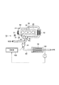
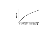
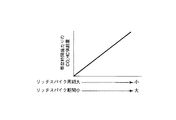
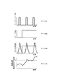
図1は本発明の一実施の形態に係るエンジンの排ガス浄化装置10の構成を示す図、図2は単位時間当りのCO,HC供給量と触媒温度との関係を示す図、図3はリッチスパイク周期及びリッチスパイク期間と単位時間当りのCO,HC供給量との関係を示す図、図4のグラフG1〜グラフG4は、排ガス浄化装置におけるリッチスパイク動作を行うためのリッチスパイク信号のタイミング、Sパージ運転を行うためのSパージ信号のタイミングと、排気配管中に供給されるCO,HC供給量と、触媒温度(触媒出口ガス温度)の時間変化を示すグラフである。
FIG. 1 is a diagram showing the configuration of an exhaust
エンジンシステム10は、ディーゼルエンジン20を備えている。ディーゼルエンジン20の吸気側には吸気配管30が接続され、排気側には排気配管40が接続されている。さらにディーゼルエンジン20の排気側と吸気配管30とは、排ガス(EGRガス)を吸気配管30に還流するEGR配管50とで接続されている。なお、図3中60は過給機、100は制御装置を示している。
The
吸気配管30には、吸気側からエアフローセンサ31、過給機60のコンプレッサ61と、インタークーラ32と、吸気スロットル33と、EGR配管50との接続部34とが設けられている。
The
排気配管40には、ディーゼルエンジン20側から、過給機60のタービン62と、排気配管40内に軽油を供給する排気軽油添加インジェクタ41と、NOx吸蔵触媒42とが設けられている。NOx吸蔵触媒42は排気配管40に流入する排ガス中のNOxを吸蔵し、かつ、排ガスがリッチになったときに吸蔵したNOxを還元処理する。
The
EGR配管50には、排気配管40側から排気ガスを冷却するEGRクーラ51と、排ガスの流量を調節するEGRバルブ52とが設けられている。
The EGR
制御部100には、排気配管40のNOx吸蔵触媒42の出口側に配置された触媒温度計測センサ101の出力が接続され、NOx吸蔵触媒42の触媒温度が常にフィードバックされている。
The
このように構成されたエンジンシステム10では、次のような動作でSパージ運転を行う。すなわち、通常のエンジン運転中は、所定の間隔でリッチスパイク動作が行われており、エンジンの燃焼制御及び排気軽油添加インジェクタ41から排気配管40内部にHCを含む軽油添加により実施される。このとき、Sパージ運転の要求があると、排気配管40内に排気軽油添加インジェクタ41からHC供給を行うことでNOx吸蔵触媒42の昇温を行う。このとき、触媒温度がSパージ温度Tに達していない場合には、昇温速度が増す方向、すなわちリッチスパイク動作の周期(図4中M)が短くなるようにリッチスパイク動作が制御される。
In the
触媒温度がSパージ温度Tに達すると、リッチスパイク動作を元の間隔に戻す。このため、触媒温度がSパージ温度T前後を推移し、過昇温とはならない。なお、触媒温度がSパージ温度Tより高い場合には、リッチスパイク周期を長くするように制御してもよい。なお、Sパージ運転が終了し通常のエンジン運転に戻ると、リッチスパイク動作は通常の周期に戻される。 When the catalyst temperature reaches the S purge temperature T, the rich spike operation is returned to the original interval. For this reason, the catalyst temperature changes around the S purge temperature T and does not become excessively high. When the catalyst temperature is higher than the S purge temperature T, the rich spike cycle may be controlled to be longer. When the S purge operation is completed and the normal engine operation is resumed, the rich spike operation is returned to the normal cycle.
上述したように、本実施の形態に係るエンジンシステム10においては、Sパージ運転が開始されると、Sパージ温度Tに対する触媒温度の偏差が大きい程、リッチスパイク周期を短くすることで、HC供給を増やし、短時間で触媒温度がSパージ温度Tに達するように制御することができる。これは図2及び図3から分かる様に、リッチスパイク周期を短くする程、単位時間当たりのCO,HCの供給量が増大し、結果的に触媒の温度上昇量を大きくできることを意味する。このため、リッチスパイクを実施しつつSパージ運転によるNOx吸蔵触媒42に吸蔵した硫黄分除去を円滑に行うことができるとともに、過昇温を防止することができる。
As described above, in the
図5のグラフL1〜L4はエンジンシステム10の変形例に係る排ガス浄化装置におけるリッチスパイク動作を行うためのリッチスパイク信号のタイミング、Sパージ運転を行うためのSパージ信号のタイミングと、排気配管中に供給されるCO,HC供給量と、触媒温度(触媒出口ガス温度)の時間変化を示すグラフである。
Graphs L1 to L4 in FIG. 5 are the timing of the rich spike signal for performing the rich spike operation, the timing of the S purge signal for performing the S purge operation, and the exhaust pipe in the exhaust gas purifying apparatus according to the modified example of the
上述した例ではリッチスパイク動作の周期を調整するようにしているが、本変形例では、リッチスパイク期間(1回当りのリッチスパイクを行っている時間)を調整するものである。すなわち、通常のエンジン運転中は、所定の間隔で、かつ、一定の期間のリッチスパイク動作が行われている。このとき、Sパージ運転の要求があると、排気配管40内にHC供給を行うことでNOx吸蔵触媒42の昇温を行う。このとき、触媒温度がSパージ温度Tに達していない場合には、昇温速度が増す方向、すなわちリッチスパイク動作の期間(図5中N)が長くなるようにリッチスパイク動作が制御される。
In the example described above, the cycle of the rich spike operation is adjusted, but in this modification, the rich spike period (time during which rich spike is performed once) is adjusted. That is, during normal engine operation, a rich spike operation is performed at a predetermined interval and for a certain period. At this time, if there is a request for the S purge operation, the temperature of the
触媒温度がSパージ温度Tに達すると、リッチスパイク期間が元の長さに戻る。このため、触媒温度がSパージ温度T前後を推移し、過昇温とはならない。なお、触媒温度がSパージ温度Tより高い場合には、リッチスパイク期間を短くするように制御してもよい。なお、Sパージ運転が終了し通常のエンジン運転に戻ると、リッチスパイク期間は通常の長さに戻される。本変形例においても、上述したリッチスパイク周期を制御する場合と同様の効果を得ることができる。 When the catalyst temperature reaches the S purge temperature T, the rich spike period returns to the original length. For this reason, the catalyst temperature changes around the S purge temperature T and does not become excessively high. When the catalyst temperature is higher than the S purge temperature T, the rich spike period may be controlled to be shortened. When the S purge operation is finished and the normal engine operation is resumed, the rich spike period is returned to the normal length. Also in this modification, the same effect as the case of controlling the rich spike cycle described above can be obtained.
なお、本発明は前記実施の形態に限定されるものではない。例えば、上述した例では、リッチスパイク周期、リッチスパイク期間のいずれかを制御しているが、両者を同時に制御するようにしてもよい。この他、本発明の要旨を逸脱しない範囲で種々変形実施可能であるのは勿論である。 The present invention is not limited to the above embodiment. For example, in the above-described example, either the rich spike cycle or the rich spike period is controlled, but both may be controlled simultaneously. Of course, various modifications can be made without departing from the scope of the present invention.
10…エンジンシステム、20…ディーゼルエンジン、30…吸気配管、40…排気配管、41…排気軽油添加インジェクタ、42…NOx吸蔵触媒、50…EGR配管、52…EGRバルブ、60…過給機、100…制御部、101…触媒温度測定センサ。
DESCRIPTION OF
Claims (4)
前記排気通路内にHCを含む還元剤成分を供給する還元剤供給部と、
前記還元剤供給部を作動させて空燃比を一時的にリッチ側に制御するリッチスパイク動作を所定時間毎に行うリッチスパイク制御部と、
前記触媒にHC成分を加えるとともに、所定の温度以上に加熱することで触媒に吸蔵した硫黄分を除去するSパージ運転の要否を判定するSパージ制御部と、
前記触媒の温度を計測する触媒温度計測センサとを備え、
前記Sパージ制御部によりSパージが必要であると判定された場合に前記リッチスパイク制御部は、前記触媒温度計測センサにより計測された温度に対する前記所定温度との偏差に基づいて、前記リッチスパイク動作の動作周期を制御することを特徴とするエンジンの排ガス浄化装置。 A catalyst that is provided in the exhaust passage of the engine, stores NOx in the exhaust gas flowing into the exhaust passage, and NOx is reduced when the air-fuel ratio of the exhaust gas becomes rich;
A reducing agent supply unit for supplying a reducing agent component containing HC into the exhaust passage;
A rich spike control unit that performs a rich spike operation for operating the reducing agent supply unit to temporarily control the air-fuel ratio to the rich side every predetermined time;
An S purge control unit that determines whether or not an S purge operation is required to remove the sulfur content stored in the catalyst by adding an HC component to the catalyst and heating the catalyst to a predetermined temperature or higher;
A catalyst temperature measuring sensor for measuring the temperature of the catalyst,
When the S purge control unit determines that S purge is necessary, the rich spike control unit performs the rich spike operation based on a deviation from the predetermined temperature with respect to the temperature measured by the catalyst temperature measurement sensor. An exhaust gas purifying device for an engine characterized by controlling the operation cycle of the engine.
前記排気通路内にHCを含む還元剤成分を供給する還元剤供給部と、
前記還元剤供給部を作動させて空燃比を一時的にリッチ側に制御するリッチスパイク動作を所定時間毎に行うリッチスパイク制御部と、
前記触媒にHC成分を加えるとともに、所定の温度以上に加熱することで触媒に吸蔵した硫黄分を除去するSパージ運転の要否を判定するSパージ制御部と、
前記触媒の温度を計測する触媒温度計測センサとを備え、
前記Sパージ制御部によりSパージが必要であると判定された場合に前記リッチスパイク制御部は、前記触媒温度計測センサにより計測された温度に対する前記所定温度との偏差に基づいて、前記リッチスパイク動作の動作期間を制御することを特徴とするエンジンの排ガス浄化装置。 A catalyst that is provided in the exhaust passage of the engine, stores NOx in the exhaust gas flowing into the exhaust passage, and NOx is reduced when the air-fuel ratio of the exhaust gas becomes rich;
A reducing agent supply unit for supplying a reducing agent component containing HC into the exhaust passage;
A rich spike control unit that performs a rich spike operation for operating the reducing agent supply unit to temporarily control the air-fuel ratio to the rich side every predetermined time;
An S purge control unit that determines whether or not an S purge operation is required to remove the sulfur content stored in the catalyst by adding an HC component to the catalyst and heating the catalyst to a predetermined temperature or higher;
A catalyst temperature measurement sensor for measuring the temperature of the catalyst,
When the S purge control unit determines that S purge is necessary, the rich spike control unit performs the rich spike operation based on a deviation from the predetermined temperature with respect to the temperature measured by the catalyst temperature measurement sensor. An exhaust gas purifying apparatus for an engine characterized by controlling an operation period of the engine.
Priority Applications (5)
| Application Number | Priority Date | Filing Date | Title |
|---|---|---|---|
| JP2004107807A JP2005291100A (en) | 2004-03-31 | 2004-03-31 | Exhaust emission control device for engine |
| US11/093,027 US20050229589A1 (en) | 2004-03-31 | 2005-03-29 | Exhaust gas purifying device for engine |
| DE102005014873A DE102005014873A1 (en) | 2004-03-31 | 2005-03-30 | Emission control device for a motor |
| KR1020050027048A KR100629205B1 (en) | 2004-03-31 | 2005-03-31 | Exhaust gas cleaning device for engine |
| CNA2005100562122A CN1676892A (en) | 2004-03-31 | 2005-03-31 | Exhaust gas purifying device for engine |
Applications Claiming Priority (1)
| Application Number | Priority Date | Filing Date | Title |
|---|---|---|---|
| JP2004107807A JP2005291100A (en) | 2004-03-31 | 2004-03-31 | Exhaust emission control device for engine |
Publications (1)
| Publication Number | Publication Date |
|---|---|
| JP2005291100A true JP2005291100A (en) | 2005-10-20 |
Family
ID=35049595
Family Applications (1)
| Application Number | Title | Priority Date | Filing Date |
|---|---|---|---|
| JP2004107807A Withdrawn JP2005291100A (en) | 2004-03-31 | 2004-03-31 | Exhaust emission control device for engine |
Country Status (5)
| Country | Link |
|---|---|
| US (1) | US20050229589A1 (en) |
| JP (1) | JP2005291100A (en) |
| KR (1) | KR100629205B1 (en) |
| CN (1) | CN1676892A (en) |
| DE (1) | DE102005014873A1 (en) |
Cited By (2)
| Publication number | Priority date | Publication date | Assignee | Title |
|---|---|---|---|---|
| JP2013053583A (en) * | 2011-09-05 | 2013-03-21 | Mitsubishi Motors Corp | Exhaust emission control device of internal combustion engine |
| JP5293735B2 (en) * | 2009-03-31 | 2013-09-18 | トヨタ自動車株式会社 | Exhaust gas purification system for internal combustion engine |
Families Citing this family (12)
| Publication number | Priority date | Publication date | Assignee | Title |
|---|---|---|---|---|
| JP4241784B2 (en) * | 2006-08-30 | 2009-03-18 | トヨタ自動車株式会社 | Exhaust gas purification system for internal combustion engine |
| DE102007004602B4 (en) * | 2007-01-30 | 2009-05-28 | Continental Automotive Gmbh | A heating device for heating a complex salt storage |
| US20090199547A1 (en) * | 2008-02-08 | 2009-08-13 | Gm Global Technology Operations, Inc. | Method and apparatus for exhaust aftertreatment in a spark-ignition direct-injection internal combustion engine |
| WO2009130800A1 (en) * | 2008-04-25 | 2009-10-29 | トヨタ自動車株式会社 | Exhaust purification system for internal combustion engine |
| US8161731B2 (en) * | 2008-05-12 | 2012-04-24 | Caterpillar Inc. | Selective catalytic reduction using controlled catalytic deactivation |
| JPWO2011101898A1 (en) * | 2010-02-17 | 2013-06-17 | トヨタ自動車株式会社 | Exhaust gas purification device for internal combustion engine |
| GB2478721B (en) * | 2010-03-15 | 2017-07-05 | Gm Global Tech Operations Llc | Method for managing a desulphurization phase of a catalyst device of an internal combustion engine. |
| JP2011252447A (en) * | 2010-06-02 | 2011-12-15 | Mitsubishi Heavy Ind Ltd | Internal combustion engine with denitration part and ship having the same |
| KR101619184B1 (en) * | 2010-11-03 | 2016-05-10 | 현대자동차 주식회사 | System for desulfurization of oxidation catalyst and method thereof |
| JP2013036393A (en) * | 2011-08-08 | 2013-02-21 | Hitachi Constr Mach Co Ltd | Engine control system of work machine |
| JP6733651B2 (en) * | 2017-12-27 | 2020-08-05 | トヨタ自動車株式会社 | Exhaust gas purification device for internal combustion engine |
| JP6729543B2 (en) * | 2017-12-27 | 2020-07-22 | トヨタ自動車株式会社 | Exhaust gas purification device for internal combustion engine |
Family Cites Families (7)
| Publication number | Priority date | Publication date | Assignee | Title |
|---|---|---|---|---|
| DE59807160D1 (en) * | 1997-07-19 | 2003-03-20 | Volkswagen Ag | Method and device for monitoring the de-sulfation in NOx storage catalysts |
| JP3518368B2 (en) | 1998-10-13 | 2004-04-12 | 日産自動車株式会社 | Engine exhaust purification device |
| DE19961165A1 (en) * | 1999-12-17 | 2001-08-02 | Volkswagen Ag | Process for the desulfurization of a NO¶x¶ storage catalytic converter arranged in an exhaust gas duct of an internal combustion engine |
| JP3757856B2 (en) * | 2001-12-07 | 2006-03-22 | トヨタ自動車株式会社 | Exhaust gas purification device |
| JP3896925B2 (en) * | 2002-08-26 | 2007-03-22 | トヨタ自動車株式会社 | Exhaust gas purification method for internal combustion engine |
| US6758035B2 (en) * | 2002-09-18 | 2004-07-06 | Arvin Technologies, Inc. | Method and apparatus for purging SOX from a NOX trap |
| US6779339B1 (en) * | 2003-05-02 | 2004-08-24 | The United States Of America As Represented By The Environmental Protection Agency | Method for NOx adsorber desulfation in a multi-path exhaust system |
-
2004
- 2004-03-31 JP JP2004107807A patent/JP2005291100A/en not_active Withdrawn
-
2005
- 2005-03-29 US US11/093,027 patent/US20050229589A1/en not_active Abandoned
- 2005-03-30 DE DE102005014873A patent/DE102005014873A1/en not_active Withdrawn
- 2005-03-31 CN CNA2005100562122A patent/CN1676892A/en active Pending
- 2005-03-31 KR KR1020050027048A patent/KR100629205B1/en not_active Expired - Fee Related
Cited By (3)
| Publication number | Priority date | Publication date | Assignee | Title |
|---|---|---|---|---|
| JP5293735B2 (en) * | 2009-03-31 | 2013-09-18 | トヨタ自動車株式会社 | Exhaust gas purification system for internal combustion engine |
| US8650863B2 (en) | 2009-03-31 | 2014-02-18 | Toyota Jidosha Kabushiki Kaisha | Exhaust gas purification system for an internal combustion engine |
| JP2013053583A (en) * | 2011-09-05 | 2013-03-21 | Mitsubishi Motors Corp | Exhaust emission control device of internal combustion engine |
Also Published As
| Publication number | Publication date |
|---|---|
| DE102005014873A1 (en) | 2005-11-17 |
| KR100629205B1 (en) | 2006-09-27 |
| US20050229589A1 (en) | 2005-10-20 |
| CN1676892A (en) | 2005-10-05 |
| KR20060045081A (en) | 2006-05-16 |
Similar Documents
| Publication | Publication Date | Title |
|---|---|---|
| US7993582B2 (en) | Sulfur purge control device for an internal combustion engine | |
| US6792751B2 (en) | Exhaust gas purification device and method for diesel engine | |
| CN101784769B (en) | Exhaust gas purification system for internal combustion engine | |
| JP2005048716A (en) | Exhaust gas recirculation control device for internal combustion engine | |
| JP4349423B2 (en) | Exhaust gas purification system for internal combustion engine | |
| KR100629205B1 (en) | Exhaust gas cleaning device for engine | |
| US20070277509A1 (en) | Exhaust gas purification system and method of purifying exhaust gas | |
| JP6268688B1 (en) | Engine exhaust purification control system | |
| JP4572709B2 (en) | Exhaust gas purification system for internal combustion engine | |
| JP4311169B2 (en) | Exhaust gas purification device for internal combustion engine | |
| JP6230007B1 (en) | Engine exhaust purification system | |
| JP6230006B1 (en) | Engine exhaust purification system | |
| EP1887202B1 (en) | Sulfur purge control device for an internal combustion engine | |
| JP2002161733A (en) | Exhaust gas purification device for internal combustion engine | |
| JP4893493B2 (en) | Exhaust gas purification device for internal combustion engine | |
| JP2010053813A (en) | Hydrogen internal combustion engine | |
| JP6230008B1 (en) | Engine exhaust purification system | |
| JP3632582B2 (en) | Exhaust gas purification device for internal combustion engine | |
| JP6268685B1 (en) | Engine exhaust purification control system | |
| JP2008175194A (en) | Control device for internal combustion engine | |
| JP2004360488A (en) | Exhaust purification device for internal combustion engine | |
| JP7347345B2 (en) | Purification control device | |
| JP2005291095A (en) | Exhaust emission control device for engine | |
| JP4063743B2 (en) | Fuel injection timing control device for internal combustion engine | |
| JP2008075571A (en) | Control device for internal combustion engine |
Legal Events
| Date | Code | Title | Description |
|---|---|---|---|
| A621 | Written request for application examination |
Free format text: JAPANESE INTERMEDIATE CODE: A621 Effective date: 20070112 |
|
| A761 | Written withdrawal of application |
Free format text: JAPANESE INTERMEDIATE CODE: A761 Effective date: 20070806 |