JP2005291013A - Cooling structure for cylinder block - Google Patents
Cooling structure for cylinder block Download PDFInfo
- Publication number
- JP2005291013A JP2005291013A JP2004103660A JP2004103660A JP2005291013A JP 2005291013 A JP2005291013 A JP 2005291013A JP 2004103660 A JP2004103660 A JP 2004103660A JP 2004103660 A JP2004103660 A JP 2004103660A JP 2005291013 A JP2005291013 A JP 2005291013A
- Authority
- JP
- Japan
- Prior art keywords
- cylinder block
- water jacket
- cooling
- bore
- cooling water
- Prior art date
- Legal status (The legal status is an assumption and is not a legal conclusion. Google has not performed a legal analysis and makes no representation as to the accuracy of the status listed.)
- Granted
Links
- 238000001816 cooling Methods 0.000 title claims abstract description 62
- XLYOFNOQVPJJNP-UHFFFAOYSA-N water Substances O XLYOFNOQVPJJNP-UHFFFAOYSA-N 0.000 claims abstract description 99
- 239000000498 cooling water Substances 0.000 claims abstract description 88
- 125000006850 spacer group Chemical group 0.000 claims abstract description 62
- 239000002826 coolant Substances 0.000 claims abstract description 30
- 230000001737 promoting effect Effects 0.000 claims abstract description 16
- 238000000034 method Methods 0.000 description 6
- 229910000838 Al alloy Inorganic materials 0.000 description 4
- 230000000694 effects Effects 0.000 description 4
- 239000000463 material Substances 0.000 description 4
- 230000002093 peripheral effect Effects 0.000 description 3
- 238000011144 upstream manufacturing Methods 0.000 description 3
- 229910001018 Cast iron Inorganic materials 0.000 description 2
- 230000007423 decrease Effects 0.000 description 2
- 238000004512 die casting Methods 0.000 description 2
- 238000001746 injection moulding Methods 0.000 description 2
- 238000003754 machining Methods 0.000 description 2
- 238000004519 manufacturing process Methods 0.000 description 2
- 229910000640 Fe alloy Inorganic materials 0.000 description 1
- XAGFODPZIPBFFR-UHFFFAOYSA-N aluminium Chemical compound [Al] XAGFODPZIPBFFR-UHFFFAOYSA-N 0.000 description 1
- 229910052782 aluminium Inorganic materials 0.000 description 1
- 238000013459 approach Methods 0.000 description 1
- 238000002485 combustion reaction Methods 0.000 description 1
- 238000005520 cutting process Methods 0.000 description 1
- 238000009826 distribution Methods 0.000 description 1
- 238000005553 drilling Methods 0.000 description 1
- 239000012530 fluid Substances 0.000 description 1
- 229910010272 inorganic material Inorganic materials 0.000 description 1
- 239000011147 inorganic material Substances 0.000 description 1
- 239000007769 metal material Substances 0.000 description 1
- 238000012986 modification Methods 0.000 description 1
- 230000004048 modification Effects 0.000 description 1
- 238000003672 processing method Methods 0.000 description 1
- 239000011347 resin Substances 0.000 description 1
- 229920005989 resin Polymers 0.000 description 1
- 238000007789 sealing Methods 0.000 description 1
Images
Classifications
-
- F—MECHANICAL ENGINEERING; LIGHTING; HEATING; WEAPONS; BLASTING
- F01—MACHINES OR ENGINES IN GENERAL; ENGINE PLANTS IN GENERAL; STEAM ENGINES
- F01P—COOLING OF MACHINES OR ENGINES IN GENERAL; COOLING OF INTERNAL-COMBUSTION ENGINES
- F01P3/00—Liquid cooling
- F01P3/02—Arrangements for cooling cylinders or cylinder heads
-
- F—MECHANICAL ENGINEERING; LIGHTING; HEATING; WEAPONS; BLASTING
- F01—MACHINES OR ENGINES IN GENERAL; ENGINE PLANTS IN GENERAL; STEAM ENGINES
- F01P—COOLING OF MACHINES OR ENGINES IN GENERAL; COOLING OF INTERNAL-COMBUSTION ENGINES
- F01P9/00—Cooling having pertinent characteristics not provided for in, or of interest apart from, groups F01P1/00 - F01P7/00
-
- F—MECHANICAL ENGINEERING; LIGHTING; HEATING; WEAPONS; BLASTING
- F02—COMBUSTION ENGINES; HOT-GAS OR COMBUSTION-PRODUCT ENGINE PLANTS
- F02F—CYLINDERS, PISTONS OR CASINGS, FOR COMBUSTION ENGINES; ARRANGEMENTS OF SEALINGS IN COMBUSTION ENGINES
- F02F1/00—Cylinders; Cylinder heads
- F02F1/02—Cylinders; Cylinder heads having cooling means
- F02F1/10—Cylinders; Cylinder heads having cooling means for liquid cooling
- F02F1/108—Siamese-type cylinders, i.e. cylinders cast together
-
- F—MECHANICAL ENGINEERING; LIGHTING; HEATING; WEAPONS; BLASTING
- F02—COMBUSTION ENGINES; HOT-GAS OR COMBUSTION-PRODUCT ENGINE PLANTS
- F02F—CYLINDERS, PISTONS OR CASINGS, FOR COMBUSTION ENGINES; ARRANGEMENTS OF SEALINGS IN COMBUSTION ENGINES
- F02F1/00—Cylinders; Cylinder heads
- F02F1/02—Cylinders; Cylinder heads having cooling means
- F02F1/10—Cylinders; Cylinder heads having cooling means for liquid cooling
- F02F1/14—Cylinders with means for directing, guiding or distributing liquid stream
Landscapes
- Engineering & Computer Science (AREA)
- Chemical & Material Sciences (AREA)
- Combustion & Propulsion (AREA)
- Mechanical Engineering (AREA)
- General Engineering & Computer Science (AREA)
- Physics & Mathematics (AREA)
- Thermal Sciences (AREA)
- Cylinder Crankcases Of Internal Combustion Engines (AREA)
Abstract
Description
この発明は、シリンダブロックの冷却構造に関し、より特定的には、シリンダブロックのボア壁を均一に冷却することができる、シリンダブロックの冷却構造に関するものである。 The present invention relates to a cylinder block cooling structure, and more particularly to a cylinder block cooling structure capable of uniformly cooling a bore wall of a cylinder block.
従来、シリンダブロックの冷却構造は、たとえば特開2002−30989号公報(特許文献1)に開示されている。
上記文献では、シリンダブロックのウォータジャケットに、シリンダブロックとは別体のウォータジャケットスペーサを挿入し、ボアの周方向のボア壁温度の均一化を図る技術が開示されている。 In the above document, a technique is disclosed in which a water jacket spacer that is separate from the cylinder block is inserted into the water jacket of the cylinder block to achieve uniform bore wall temperature in the circumferential direction of the bore.
しかしながら、上述の技術であっても、ボア壁温度の均一化を十分に図ることができなかった。 However, even with the above-described technique, the bore wall temperature cannot be sufficiently uniformed.
さらに、冷却水が直接当たらないために高温となる部分にドリルパスを設けても、ボア間領域が十分に冷却されないという問題があった。その理由として、ドリルパスの出入口をウォータジャケットスペーサが塞いでしまうため、ドリルパス内での冷却水の流量が低下することが考えられる。 Further, since the cooling water is not directly applied, there is a problem that the area between the bores is not sufficiently cooled even if a drill path is provided in a portion where the temperature becomes high. As the reason, it is conceivable that the flow rate of the cooling water in the drill path decreases because the water jacket spacer blocks the entrance / exit of the drill path.
そこで、この発明は上述のような問題点を解決するためになされたものであり、シリンダブロックを均一に冷却できる、シリンダブロックの冷却構造を提供することを目的とする。 Accordingly, the present invention has been made to solve the above-described problems, and an object thereof is to provide a cylinder block cooling structure capable of uniformly cooling the cylinder block.
この発明に従ったシリンダブロックの冷却構造は、複数のボア領域を取囲むボア壁周囲にウォータジャケット部が連続して設けられたシリンダブロックと、ウォータジャケット部に挿入されるウォータジャケットスペーサとを備え、ウォータジャケット部に冷却媒体を供給し、ボア壁温度を均一化するシリンダブロックの冷却構造であって、シリンダブロックには、隣り合うボア領域の境界近傍に位置するボア間領域と、ボア間領域近傍に位置する冷却媒体を他の領域に移送するための通路とが設けられている。通路を流れる冷却媒体の流量を増加させるための流通促進手段をさらに備える。 A cylinder block cooling structure according to the present invention includes a cylinder block in which a water jacket portion is continuously provided around a bore wall surrounding a plurality of bore regions, and a water jacket spacer inserted into the water jacket portion. A cooling structure for a cylinder block that supplies a cooling medium to the water jacket portion and makes the bore wall temperature uniform, and the cylinder block includes an inter-bore region located in the vicinity of the boundary between adjacent bore regions, and an inter-bore region A passage for transferring a cooling medium located in the vicinity to another area is provided. The apparatus further includes a flow promoting means for increasing the flow rate of the cooling medium flowing through the passage.
このように構成されたシリンダブロックの冷却構造では、通路を流れる冷却媒体の流量を増加させるための流通促進手段をさらに備えているため、ボア間領域における冷却の必要な部位の十分な冷却が可能となる。 The cylinder block cooling structure configured as described above further includes a flow promoting means for increasing the flow rate of the cooling medium flowing through the passage, so that sufficient cooling can be performed for a portion requiring cooling in the region between the bores. It becomes.
好ましくは、通路はドリルパスであり、流通促進手段は、ドリルパス開口近傍でのウォータジャケットスペーサの切欠形状である。この場合、切欠がドリルパス開口近傍に設けられるため、ドリルパス開口への冷却媒体の流入および流出を妨げることがない。その結果、ドリルパスでの冷却媒体の流通を促進することができる。 Preferably, the passage is a drill path, and the flow promoting means is a notch shape of the water jacket spacer in the vicinity of the drill path opening. In this case, since the notch is provided in the vicinity of the drill path opening, the inflow and outflow of the cooling medium to the drill path opening is not hindered. As a result, circulation of the cooling medium in the drill path can be promoted.
好ましくは、通路はドリルパスであり、流通促進手段は、ドリルパス開口近傍でのウォータジャケットスペーサの貫通孔である。この場合、ドリルパス近傍でウォータジャケットスペーサに貫通孔が存在するため、貫通孔によりドリルパスの開口近傍での冷却媒体の流出および流入を妨げることがない。その結果、ドリルパスでの冷却媒体の流通を促進することができる。 Preferably, the passage is a drill path, and the flow promoting means is a through hole of the water jacket spacer in the vicinity of the drill path opening. In this case, since the water jacket spacer has a through hole in the vicinity of the drill path, the through hole does not prevent the coolant from flowing out and flowing in near the opening of the drill path. As a result, circulation of the cooling medium in the drill path can be promoted.
より好ましくは、ウォータジャケットスペーサの外表面には溝が設けられており、この溝が貫通孔と、シリンダブロックに冷却媒体を供給するための穴とを接続する。この場合、穴から供給された冷たい冷却媒体は外表面に設けられた溝を通って貫通孔まで達し、この貫通孔からドリルパスへ供給される。その結果、ドリルパスに冷たい冷却媒体を流通させることができ、ボア間領域をさらに十分に冷却することができる。 More preferably, a groove is provided on the outer surface of the water jacket spacer, and this groove connects the through hole and a hole for supplying a cooling medium to the cylinder block. In this case, the cold cooling medium supplied from the hole reaches the through hole through the groove provided on the outer surface, and is supplied from the through hole to the drill path. As a result, a cold cooling medium can be circulated through the drill path, and the region between the bores can be further sufficiently cooled.
好ましくは、流通促進手段はウォータジャケットスペーサと一体に設けられた堰部分である。この場合、ウォータジャケットスペーサに堰部分を設けるだけで通路での冷却媒体の流通を促進することができ、簡単な加工により冷却促進手段を実現することができる。 Preferably, the distribution promoting means is a dam portion provided integrally with the water jacket spacer. In this case, the circulation of the cooling medium in the passage can be promoted only by providing the weir portion in the water jacket spacer, and the cooling promoting means can be realized by simple processing.
この発明に従えば、均一な冷却を実現できるシリンダブロックの冷却構造を提供することができる。 According to the present invention, it is possible to provide a cylinder block cooling structure capable of realizing uniform cooling.
以下、この発明の実施の形態について、図面を参照して説明する。なお、以下の実施の形態では同一または相当する部分については同一の参照符号を付し、その説明については繰返さない。 Embodiments of the present invention will be described below with reference to the drawings. In the following embodiments, the same or corresponding parts are denoted by the same reference numerals, and description thereof will not be repeated.
(実施の形態1)
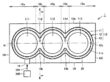
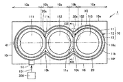
図1は、この発明の実施の形態1に従ったシリンダブロックの冷却構造の平面図である。図1を参照して、この発明の実施の形態1に従ったシリンダブロックの冷却構造1では、シリンダブロック10が冷却媒体としての冷却水により冷却される。シリンダブロック10は、シリンダライナ集合体11、シリンダライナ集合体11を取囲む溝形状のウォータジャケット部12およびウォータジャケット部12を取囲むシリンダブロックベース部13から構成される。
(Embodiment 1)
1 is a plan view of a cooling structure for a cylinder block according to
シリンダライナ集合体11は、3つのボア領域111,112,113を有し、ボア領域111,112,113を取囲む鉄合金を、アルミニウム合金で取囲んだ構造とされる。シリンダライナ集合体11は、冷却媒体を流すためのウォータジャケット部12により取囲まれる。ウォータジャケット部12は凹形状であり、シリンダライナ集合体11に沿った形状である。シリンダブロックベース部13はエンジンブロック本体であり、アルミニウム合金により構成される。
The
シリンダブロックベース部13は冷却媒体の入口としての冷却水入口14が設けられる。シリンダブロックベース部13を覆うようにガスケットが設けられ、このガスケットには、冷却媒体の通路となるガスケット孔41が設けられる。ガスケット上にはエンジンヘッドが載置され、ガスケット孔41に繋がるような通路がエンジンヘッド内に設けられており、この通路内を冷却媒体が通過することでエンジンヘッドを冷却することができる。
The cylinder
ウォータジャケットスペーサ20はウォータジャケット部12に嵌め合わされ、シリンダライナ集合体11のボア壁11bとの間で所定の隙間を有するように構成される。
The
ウォータジャケット部12内での冷却水の流れについて説明すると、冷却水入口14が流れの上流であり、ガスケット孔41が流れの下流であり、上流から下流において、シリンダライナ集合体11のボア壁11bと、ウォータジャケットスペーサ20との間を冷却水が流れる。また、ウォータジャケットスペーサ20とシリンダブロックベース部13との間も冷却水が流れる。
The flow of the cooling water in the
シリンダブロック10のフロント側10fで流れはUターンし、吸気側10iから排気側10eへ流れが転ずる。リア側10rではガスケット孔41に流れが繋がり、エンジンヘッド側へ冷却水が導かれる。上述の冷却水の流れは、ブロック先行Uターン冷却の例である。なお、図中の矢印101は、冷却水の流れを示す。なお、この冷却水の流れに限定されるものではなく、Uターンしない方式、すなわち、リア側10rから冷却水を入力してフロント側10fへ冷却水を流す方式、これとは逆に、フロント側10fからリア側10rへ冷却水を流す方式を採用してもよい。
The flow makes a U-turn on the
ウォータジャケットスペーサ20は、シリンダブロックベース部13との間においても所定の隙間が生じるように配置される。この隙間をも冷却水が流れ、シリンダブロックベース部13の熱を冷却水が奪い取る。冷却水は、冷却水入口14から導かれ、それぞれのボア領域111,112,113を取囲むボア壁11bに沿って流れ、このときボア壁11bから熱を奪い取る。これにより、それぞれのボア領域111,112,113の温度を低下させることができる。
The
それぞれのボア領域111,112,113の接続領域である境界10k近傍がボア間領域10bとなる。ボア間領域10bは、その他の領域10aの間に配置される。ボア間領域10bでは、流れの方向が急激に変化しているため、流れに淀みが生じやすい。そこで、このボア間領域10bを冷却するためにドリルパス11dが設けられている。ドリルパス11dはボア間領域10bにおいてシリンダライナ集合体11を貫通するように設けられ、ドリルパス11d内には冷却水が流れる。これにより、ボア間領域10bを構成するシリンダライナ集合体11から熱を奪い取ることが可能である。ドリルパス11dは、複数のボア領域111,112,113を繋ぐ中心線10cを跨ぐように配置される。
The vicinity of the
ウォータポンプ300から矢印101で示す方向に冷却水入口14に供給された冷却水のうち、一部はボア壁11bに沿って流れることでボア壁11bを冷却し、また他の一部は、ドリルパス11d内を流れることでシリンダライナ集合体11を冷却する。
Of the cooling water supplied from the
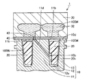
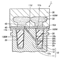
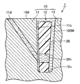
図2は、図1中のII−II線に沿った断面図である。図2を参照して、この発明の実施の形態1に従ったシリンダブロックの冷却構造1において、シリンダブロック10は、内部に位置するシリンダライナ集合体11と、シリンダライナ集合体11を取囲むように配置される、冷却媒体通路としてのウォータジャケット部12と、ウォータジャケット部12を取囲み、かつシリンダライナ集合体11に向かい合うシリンダブロックベース部13とを有する。
FIG. 2 is a cross-sectional view taken along the line II-II in FIG. Referring to FIG. 2, in cylinder
シリンダライナ集合体11は、ボア壁11bを有し、ボア壁11bは、冷却媒体としての冷却水100Wに接触している。
The
ウォータジャケット部12はシリンダライナ集合体11とシリンダブロックベース部13との間に設けられた領域であり、冷却媒体の通路としての作用を有する。なお、ウォータジャケット部12は底部12uを有し、この底部12uにおいてシリンダライナ集合体11とシリンダブロックベース部13とが接続されている。ウォータジャケット部12の幅については特に制限されるものではなく、幅がほぼ一定に構成されていてもよく、ウォータジャケット部12がV字状に形成されてもよい。この場合、ウォータジャケット部12に面するボア壁11bがテーパ面を有する。
The
シリンダブロックベース部13はアルミニウム合金製であり、ダイキャストなどの方法で構成される。なお、シリンダブロックベース部13およびシリンダライナ集合体11の材質は特に限定されるものではなく、アルミニウム合金だけでなく、鋳鉄により構成してもよい。シリンダブロックベース部13はエンジンブロックとなり、エンジンに設けられるさまざまな補機類が取付けられる。
The cylinder
シリンダブロックベース部13には、図示しない冷却水の入口が設けられており、この入口としての穴には、ウォータポンプからの冷却水100Wが導入される。なお、冷却媒体として、冷却水100Wだけでなく、ロングライフクーラント、油などのさまざまな流体を用いることが可能である。
The cylinder
シリンダブロック10の上面であるデッキ面10dにはウォータジャケット部12が露出しており、オープンデッキタイプとなっている。デッキ面10d上にはガスケット40およびエンジンヘッド30が取付けられている。ガスケット40はウォータジャケット部12を流れる冷却水100Wを封止する働きがある。
The
ウォータジャケット部12には、ウォータジャケットスペーサ20が挿入される。ウォータジャケットスペーサ20はウォータジャケット部12に沿った形状を有し、かつ、シリンダライナ集合体11を取囲む形状となっている。ウォータジャケットスペーサ20の材質としては、特に制限されるものではなく、アルミニウム、鋳鉄、その他の非金属材料、無機材料、および樹脂などのさまざまなものを採用することが可能である。
A
シリンダライナ集合体11には、貫通孔としてのドリルパス11dが設けられている。ドリルパス11dはボア壁11bからデッキ面10dにまで延び、かつガスケット孔43と連なる。そして、ガスケット孔43はヘッド通路32に一致している。
The
ドリルパス11dは、ドリルによりシリンダライナ集合体11を加工することにより構成される。なお、ドリルパス11dは、ドリル加工だけでなく、他の加工により形成されていてもよい。さらに、シリンダブロック10をダイキャストで構成する際に、鋳型の段階でドリルパス11dを設けてもよい。すなわち、ドリルパス11dは、ボア壁11bと他の領域とを接続する穴であればよく、その加工法には限定されるものではない。
The
したがって、ドリルパス11dが向かい合うボア壁11b同士を接続していてもよい。また、図2では、ドリルパス11dは直線形状であるが、これに限定されるものではなく、ドリルパス11dが曲線状であってもよい。ドリルパス11d内の冷却水の流れとしては、主として下側から上側、すなわち、ボア壁11bからデッキ面10d側へ冷却水100Wが流れる。この流れが大きくなれば大きくなるほどボア間領域10bが冷却される。したがって、ボア間領域10bを積極的に冷却するためには、この流れを妨げないような構造とする必要がある。本発明では、ウォータジャケットスペーサ20に凹みとしての切欠20kを設けている。
Therefore, the
すなわち、ドリルパス11dの冷却水の入口に対向する部分に凹部としての切欠20kを設けているため、ドリルパス11dの入口での閉塞がなくなるため、ドリルパス11d内を十分な冷却水が流れる。
That is, since the
この発明に従ったシリンダブロックの冷却構造1は、図1および図2を参照して、複数のボア領域111,112,113を取囲むボア壁11b周囲にウォータジャケット部12が連続して設けられたシリンダブロック10と、ウォータジャケット部12に挿入されるウォータジャケットスペーサ20とを備える。ウォータジャケット部12に冷却媒体としての冷却水100Wを供給し、ボア壁11b温度を均一化する。シリンダブロック10には、隣り合うボア領域111,112,113の境界10k近傍に位置するボア間領域10bと、ボア間領域10b近傍に位置する冷却媒体を他の領域に移送するための通路としてのドリルパス11dとが設けられている。ドリルパス11dを流れる冷却媒体の流量を増加させるための流通促進手段としての切欠20kがウォータジャケットスペーサ20に設けられている。
1 and 2, a cylinder
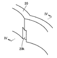
図3は、図1および図2で示すウォータジャケットスペーサの部分的な斜視図である。図2を参照して、ウォータジャケットスペーサ20の内周面側に切欠20kが設けられている。切欠20kは、ウォータジャケットスペーサ20の内周面のうち、最も張り出した部分、すなわち峰状部分を切欠くことで構成されており、一部分が切欠かれることで、この部分での冷却水の流れを促進することが可能である。なお、図2では、ウォータジャケットスペーサ20の下部領域のみに切欠20kを設けているが、これに限定されるものではなく、上部から下部に連なるように、すなわち、図2の底部12uからデッキ面10d近傍まで切欠20kが設けられている構造としてもよい。
FIG. 3 is a partial perspective view of the water jacket spacer shown in FIGS. 1 and 2. Referring to FIG. 2, a
図4は、図3中のIV−IV線に沿った断面図である。図4を参照して、切欠20kは矩形状であり、ほぼ長方形状の領域がウォータジャケットスペーサ20の一部分から切欠かれることで切欠20kが構成される。なお、切欠20kの製造方法としては、特に限定されるものではなく、たとえばウォータジャケットスペーサ20を射出成形で形成する場合には、切欠20kを有するような型内にプラスチック材料を流し込んで切欠20kを形成してもよい。また、一旦断面が長方形状のウォータジャケットスペーサ20を構成し、一部分を機械加工することで切欠20kを構成してもよい。また、切欠20kの形状としては、矩形に限定されず、曲面形状の切欠20kを採用してもよい。
4 is a cross-sectional view taken along line IV-IV in FIG. Referring to FIG. 4, the
以上のように構成された、この発明の実施の形態1に従ったシリンダブロックの冷却構造1では、ドリルパス11d内を流れる冷却水100Wの流れを妨げないために、ウォータジャケットスペーサ20に切欠20kを設けている。この切欠が存在することで、ドリルパス11dの入口付近に大きな空間が形成され、この空間からドリルパス11dへ冷却水100Wが積極的に流れ込む。そのため、ドリルパス11d内での冷却水100Wの流れを促進することができ、ボア間領域10bにおいて熱を冷却水100Wにより奪い取ることが可能となる。その結果、ボア間領域10bを十分に冷却することができ、均一な冷却が可能なシリンダブロックの冷却構造1を提供することが可能となる。
In the cylinder
(実施の形態2)
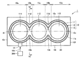
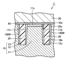
図5は、この発明の実施の形態2に従ったシリンダブロックの冷却構造の平面図である。図6は、図5中のVI−VI線に沿った断面図である。図5および図6を参照して、この発明の実施の形態2に従ったシリンダブロックの冷却構造1では、ウォータジャケットスペーサ20に貫通孔20hが形成されている。貫通孔20hは、ウォータジャケットスペーサ20の内表面から外表面20uまで貫通し、かつドリルパス11dの入口に向かい合う。
(Embodiment 2)
FIG. 5 is a plan view of a cylinder block cooling structure according to the second embodiment of the present invention. 6 is a cross-sectional view taken along line VI-VI in FIG. Referring to FIGS. 5 and 6, in the
すなわち、実施の形態2では、通路はドリルパス11dであり、流通促進手段は、ドリルパス11d開口近傍でのウォータジャケットスペーサ20の貫通孔である。貫通孔20hが存在することで、ドリルパス11dの入口、つまり、ドリルパス11dのうち、ボア壁11bに設けられた開口における水の流入を促進することができる。ドリルパス11dにウォータジャケット部12から冷却水100Wが流入すると、開口近傍の圧力が低くなるが、図6で示すように貫通孔20hを設けることにより、ウォータジャケットスペーサ20とシリンダブロックベース部13との間の領域から、ドリルパス11dへ冷却水100Wを積極的に供給することが可能となる。
That is, in the second embodiment, the passage is the
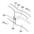
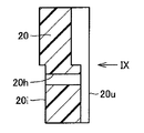
図7は、図5および図6で示すウォータジャケットスペーサの部分的な斜視図である。図8は、図7中のVIII−VIII線に沿った断面図である。図9は、図8中のIXで示す方向から見たウォータジャケットスペーサの側面図である。図7から図9を参照して、ウォータジャケットスペーサ20は、複数の筒状領域を繋ぎ合わせた形状を有し、その内周面20iに切欠20kが形成されている。切欠20kはウォータジャケットスペーサ20のうち、最も内側にせり出した峰状部分を切欠くことで構成され、その端部に貫通孔20hが設けられる。
FIG. 7 is a partial perspective view of the water jacket spacer shown in FIGS. 5 and 6. 8 is a cross-sectional view taken along line VIII-VIII in FIG. FIG. 9 is a side view of the water jacket spacer as viewed from the direction indicated by IX in FIG. 7 to 9, the
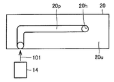
貫通孔20hを設けることで、ドリルパス内の冷却水の流量はさらに増加し、冷却性能が向上する。貫通孔20hには、冷却水通路20pが接続されている。冷却水通路20pは、図9で示すように、冷却水入口14と接続される。ウォータジャケットスペーサ20の外表面20uには、溝としての冷却水通路20pが設けられており、この冷却水通路20pが、貫通孔20hと、シリンダブロック10に冷却水を供給するための冷却水入口14とを接続する。
By providing the through
これにより、冷却水入口14から供給された冷たい冷却水は、外表面20uに設けられた冷却水通路20pを通って貫通孔20hまで達し、この貫通孔20hからドリルパス11dへ冷たい冷却水を直接供給することができる。図9で示すように、冷却水通路20pは「L」字状であるが、これに限定されるものではなく、冷却水通路20pは直線状であってもよい。さらに、冷却水通路20pが曲線状であってもよい。冷却水通路20pは、冷却水入口14と貫通孔20hとを繋ぐものであれば、その形状に関しては限定されるものではない。
Thereby, the cold cooling water supplied from the cooling
冷却水通路20pの製造方法としては、さまざまなものが考えられるが、たとえば、機械加工により冷却水通路20pを構成してもよい。また、射出成形などでウォータジャケットスペーサ20を形成する場合には、金型内に冷却水通路20pの型を設けておき、この型に沿ってプラスチックを流し込むことで冷却水通路20pを構成することができる。
Various methods for manufacturing the
冷却水通路20pの深さについては特に限定されるものではなく、外表面20uの浅い部分にのみ冷却水通路20pが設けられていてもよく、また、ほぼウォータジャケットスペーサ20を貫通するまでの深さに冷却水通路20pを設けてもよい。
The depth of the cooling
このように構成された、実施の形態2に従ったシリンダブロックの冷却構造1では、実施の形態1に従ったシリンダブロックの冷却構造1と同様の効果がある。
The cylinder
(実施の形態3)
図10は、この発明の実施の形態3に従ったシリンダブロックの冷却構造の断面図である。図10を参照し、この発明の実施の形態3に従ったシリンダブロックの冷却構造1では、ウォータジャケットスペーサ20に切欠が設けられていない点で、実施の形態2に従ったウォータジャケットスペーサ20と異なる。切欠は設けられていないものの、実施の形態3では、流通促進手段としての貫通孔20hがドリルパス11dの開口と向かい合うように配置される。
(Embodiment 3)
FIG. 10 is a cross-sectional view of a cylinder block cooling structure according to the third embodiment of the present invention. Referring to FIG. 10, in cylinder
図10では、ウォータジャケットスペーサ20とボア壁11bとの間には所定の隙間が設けられているが、この隙間を限りなく小さくしてもよい。隙間を小さくする手法としては、ウォータジャケットスペーサ20とシリンダブロックベース部13との間にたとえば、板ばねにより付勢手段を圧入するが考えられる。付勢手段を圧入することで、ウォータジャケットスペーサ20はボア壁11b側へ押される。これにより、これにより、ウォータジャケットスペーサ20とボア壁11bとを密着させることが可能である。
In FIG. 10, a predetermined gap is provided between the
また、図10では、貫通孔20hは、水平方向に延びている。しかしながら、この構成に限られるものではなく、貫通孔20hは、ドリルパス11dと同様に、右下がりに構成されていてもよい。また、右上がりに構成されていてもよい。実施の形態3では、貫通孔20hの内径はほぼ一定であるが、この内径についても特に限定されるものではなく、ドリルパス11dからシリンダブロックベース部13に近づくにつれて内径が大きくなる構成を採用してもよく、内径が小さくなる構成を採用してもよい。
In FIG. 10, the through
ウォータジャケットスペーサ20において、ドリルパス11dの入口に対向する部分に貫通孔20hを設けているため、ドリルパス11dの入口部を閉塞することを回避できる。
In the
このように構成された、この発明の実施の形態3に従ったシリンダブロックの冷却構造1でも、実施の形態1に従ったシリンダブロックの冷却構造1と同様の効果がある。
The cylinder
(実施の形態4)
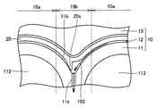
図11は、この発明の実施の形態4に従ったシリンダブロックの冷却構造の平面図である。図12は、図11中のXIIで囲んだ部分を拡大して示す平面図である。図13は、図11中のXIII−XIII線に沿った断面図である。図11から図13を参照して、この発明の実施の形態4に従ったシリンダブロックの冷却構造1では、シリンダライナ集合体11にスリット11sが設けられており、スリット11sに冷却水を導入するための堰20sがウォータジャケットスペーサ20に一体的に設けられている。
(Embodiment 4)
FIG. 11 is a plan view of a cylinder block cooling structure according to the fourth embodiment of the present invention. FIG. 12 is an enlarged plan view showing a portion surrounded by XII in FIG. 13 is a cross-sectional view taken along line XIII-XIII in FIG. 11 to 13, in cylinder
スリット11sは、シリンダライナ集合体11を貫通するように中心線10cを横切るように形成される。ボア間領域10bをスリット11sが貫通するため、スリット11sに十分に冷却水が供給されれば、ボア間領域10bを冷却することができる。しかしながら、スリット11sの両端部での圧力差が小さくなる。特に、冷却水が平行にながれる場合には、圧力差が小さい。具体的には、シリンダブロック10のリア側10rから冷却水が導入され、この導入された冷却水が二手に分かれてボア壁11bを冷却し、フロント側10fへ排出される冷却方法、または、フロント側10fから冷却水が導入され、導入された冷却水がボア壁11bを冷却した後リア側10rへ排出される冷却方法では、スリット11sの出入り口における差圧がほとんど得られず、スリット11sによっては、ボア間領域10bが十分に冷却されない。
The
また、図11で示すように、冷却水入口14から冷却水が導入され、ガスケット孔41から冷却水が抜ける冷却方法においても、スリット11sの上流と下流側での差圧は、冷却水通路の圧力損失分であるため、十分な差圧が得られず、冷却不足となる問題があった。
Further, as shown in FIG. 11, also in the cooling method in which the cooling water is introduced from the cooling
本発明では、ウォータジャケットスペーサ20に、一体的に堰20sを設けている。堰20sを設けることにより、堰20s近辺で冷却水の圧力が上昇し、スリット11sへ積極的に冷却水を導入することが可能となる。これにより、ボア間領域10bを十分に冷却することが可能となる。すなわち、冷却促進手段は、ウォータジャケットスペーサ20と一体的に設けられた堰20sであり、ボア間領域10b近傍に位置する冷却媒体を他の領域に移送するための通路としてのスリット11sが設けられている。
In the present invention, the
このように構成された、実施の形態4に従ったシリンダブロックの冷却構造でも、実施の形態1に従ったシリンダブロックの冷却構造と同様の効果がある。 The cylinder block cooling structure according to the fourth embodiment configured as described above has the same effect as the cylinder block cooling structure according to the first embodiment.
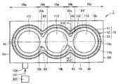
(実施の形態5)
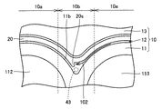
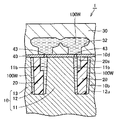
図14は、この発明の実施の形態5に従ったシリンダブロックの冷却構造の平面図である。図15は、図14中のXVで囲んだ部分を拡大して示す平面図である。図16は、図14中のXVI−XVI線に沿った断面図である。図14から図16を参照して、この発明の実施の形態5に従ったシリンダブロックの冷却構造1では、ウォータジャケットスペーサ20に、一体的に堰20sが設けられており、堰20s近傍には、ガスケット孔43が設けられている。ガスケット孔43はヘッド通路32に連なっており、ガスケット孔43はヘッド通路32とウォータジャケット部12との間の経路となる。ヘッドガスケット孔としてガスケット孔43はボア間領域10bに設けられており、ボア間領域10b近傍に位置する冷却媒体を他の領域に移送するための通路としての役割を果たす。ガスケット孔43の形状としては、図14および図15では円形状としているが、これに限られるものではなく、多角形の形状とされてもよい。ガスケット孔43はガスケット40を貫通し、ヘッド内の冷却水通路としてのヘッド通路32内の冷却水100Wをウォータジャケット部12へ導き、かつウォータジャケット部12内の冷却水100Wをヘッド通路32へ導く。
(Embodiment 5)
FIG. 14 is a plan view of a cylinder block cooling structure according to the fifth embodiment of the present invention. FIG. 15 is an enlarged plan view showing a portion surrounded by XV in FIG. 16 is a cross-sectional view taken along line XVI-XVI in FIG. 14 to 16, in cylinder
ウォータジャケットスペーサ20に堰20sを一体的に設けることにより、ガスケット孔43付近で冷却水100Wの圧力が上昇する。このため、ガスケット孔43からヘッド通路32に抜ける冷却水の流量が増加するため、ボア間領域10bでの冷却水の流通を促進でき、ボア間領域10bを積極的に冷却することができる。
By integrally providing the
このように構成された、実施の形態5に従ったシリンダブロックの冷却構造1では、実施の形態1に従ったシリンダブロックの冷却構造と同様の効果がある。
The cylinder
以上、この発明の実施の形態について説明したが、ここで示した実施の形態はさまざまに変形することが可能である。まず、1つのシリンダブロック10に設けられるボア領域の数は実施の形態に限定されず、2つ以上のボア領域が設けられてもよい。
Although the embodiment of the present invention has been described above, the embodiment shown here can be variously modified. First, the number of bore regions provided in one
また、この発明が適用されるエンジンとしては、ディーゼルエンジンおよびガソリンエンジンがあり、エンジンの型式として、直列型、V型、W型、水平対向型などさまざまなエンジンに本発明を適用することが可能である。 Engines to which the present invention is applied include diesel engines and gasoline engines, and the present invention can be applied to various types of engines such as inline, V, W, and horizontally opposed types. It is.
今回開示された実施の形態はすべての点で例示であって制限的なものではないと考えられるべきである。本発明の範囲は上記した説明ではなくて特許請求の範囲によって示され、特許請求の範囲と均等の意味および範囲内でのすべての変更が含まれることが意図される。 The embodiment disclosed this time should be considered as illustrative in all points and not restrictive. The scope of the present invention is defined by the terms of the claims, rather than the description above, and is intended to include any modifications within the scope and meaning equivalent to the terms of the claims.
この発明は、内燃機関のシリンダブロックの冷却構造の分野において適用することが可能である。 The present invention can be applied in the field of a cooling structure for a cylinder block of an internal combustion engine.
1 シリンダブロックの冷却構造、10 シリンダブロック、10b ボア間領域、11 シリンダライナ集合体、11b ボア壁、11d ドリルパス、12 ウォータジャケット部、13 シリンダブロックベース部、20 ウォータジャケットスペーサ、100W 冷却水。
DESCRIPTION OF
Claims (6)
前記ウォータジャケット部に挿入されるウォータジャケットスペーサとを備え、
前記ウォータジャケット部に冷却媒体を供給し、前記ボア壁温度を均一化するシリンダブロックの冷却構造であって、
前記シリンダブロックには、前記隣り合うボア領域の境界近傍に位置するボア間領域と、前記ボア間領域に位置する冷却媒体を他の領域に移送するための通路とが設けられ、
前記通路を流れる冷却媒体の流量を増加させるための流通促進手段をさらに備えた、シリンダブロックの冷却構造。 A cylinder block in which a water jacket portion is continuously provided around a bore wall surrounding a plurality of bore regions;
A water jacket spacer to be inserted into the water jacket portion;
A cooling structure of a cylinder block that supplies a cooling medium to the water jacket portion and equalizes the bore wall temperature,
The cylinder block is provided with an inter-bore region located in the vicinity of the boundary between the adjacent bore regions, and a passage for transferring a cooling medium located in the inter-bore region to another region,
A cylinder block cooling structure, further comprising a flow promoting means for increasing a flow rate of the cooling medium flowing through the passage.
Priority Applications (4)
| Application Number | Priority Date | Filing Date | Title |
|---|---|---|---|
| JP2004103660A JP4279714B2 (en) | 2004-03-31 | 2004-03-31 | Cylinder block cooling structure |
| US11/082,876 US7278381B2 (en) | 2004-03-31 | 2005-03-18 | Cooling structure of cylinder block |
| FR0503003A FR2868478B1 (en) | 2004-03-31 | 2005-03-25 | COOLING STRUCTURE OF A CYLINDERS BLOCK |
| DE102005014755.0A DE102005014755B8 (en) | 2004-03-31 | 2005-03-31 | Cooling structure for a cylinder block |
Applications Claiming Priority (1)
| Application Number | Priority Date | Filing Date | Title |
|---|---|---|---|
| JP2004103660A JP4279714B2 (en) | 2004-03-31 | 2004-03-31 | Cylinder block cooling structure |
Publications (2)
| Publication Number | Publication Date |
|---|---|
| JP2005291013A true JP2005291013A (en) | 2005-10-20 |
| JP4279714B2 JP4279714B2 (en) | 2009-06-17 |
Family
ID=34982648
Family Applications (1)
| Application Number | Title | Priority Date | Filing Date |
|---|---|---|---|
| JP2004103660A Expired - Fee Related JP4279714B2 (en) | 2004-03-31 | 2004-03-31 | Cylinder block cooling structure |
Country Status (4)
| Country | Link |
|---|---|
| US (1) | US7278381B2 (en) |
| JP (1) | JP4279714B2 (en) |
| DE (1) | DE102005014755B8 (en) |
| FR (1) | FR2868478B1 (en) |
Cited By (7)
| Publication number | Priority date | Publication date | Assignee | Title |
|---|---|---|---|---|
| JP2014208992A (en) * | 2013-03-22 | 2014-11-06 | 本田技研工業株式会社 | Internal combustion engine cooling structure |
| JP2015083791A (en) * | 2013-10-25 | 2015-04-30 | マツダ株式会社 | Cooling device of engine |
| JP2015108345A (en) * | 2013-12-05 | 2015-06-11 | マツダ株式会社 | Multicylinder engine cooling structure |
| JP2015190403A (en) * | 2014-03-28 | 2015-11-02 | マツダ株式会社 | Engine cooling structure |
| JP2015224627A (en) * | 2014-05-30 | 2015-12-14 | マツダ株式会社 | Cooling structure for multi-cylinder engine |
| WO2017104555A1 (en) * | 2015-12-16 | 2017-06-22 | ニチアス株式会社 | Water jacket spacer manufacturing method and water jacket spacer |
| US10006400B2 (en) | 2015-12-07 | 2018-06-26 | Hyundai Motor Company | Block insert and cylinder structure of vehicle engine including the same |
Families Citing this family (29)
| Publication number | Priority date | Publication date | Assignee | Title |
|---|---|---|---|---|
| JP4446989B2 (en) * | 2006-09-08 | 2010-04-07 | トヨタ自動車株式会社 | Cylinder block and internal combustion engine |
| DE102007041010A1 (en) * | 2007-08-29 | 2009-03-05 | Mahle International Gmbh | Cylinder crankcase for an internal combustion engine |
| DE102008015002B4 (en) | 2008-03-19 | 2024-04-25 | Dr. Ing. H.C. F. Porsche Aktiengesellschaft | Cooling of the cylinder head and crankcase of an internal combustion engine |
| EP2309114B1 (en) * | 2009-07-30 | 2012-09-12 | Ford Global Technologies, LLC | Cooling system |
| DE102010047325B4 (en) * | 2010-10-01 | 2021-11-18 | Daimler Ag | Internal combustion engine with a cylinder housing made of light metal cast and with cylinder liners made of rough cast |
| DE102012200527A1 (en) * | 2012-01-16 | 2013-07-18 | Bayerische Motoren Werke Aktiengesellschaft | Internal combustion engine with at least three cylinders |
| JP5864401B2 (en) * | 2012-11-09 | 2016-02-17 | 本田技研工業株式会社 | Water jacket structure of internal combustion engine |
| JP6199911B2 (en) * | 2014-03-31 | 2017-09-20 | トヨタ自動車株式会社 | Water jacket spacer |
| US9488127B2 (en) * | 2014-04-16 | 2016-11-08 | Ford Global Technologies, Llc | Bore bridge and cylinder cooling |
| US9334828B2 (en) * | 2014-06-23 | 2016-05-10 | Ford Global Technologies, Llc | Bore bridge and cylinder cooling |
| DE102014214376A1 (en) * | 2014-07-23 | 2016-01-28 | Volkswagen Aktiengesellschaft | Engine component of a reciprocating engine |
| US9470176B2 (en) * | 2014-08-01 | 2016-10-18 | Ford Global Technologies, Llc | Bore bridge and cylinder cooling |
| US9670822B2 (en) * | 2014-09-08 | 2017-06-06 | Ford Global Technologies, Llc | Bore bridge and cylinder cooling |
| US10161352B2 (en) * | 2014-10-27 | 2018-12-25 | GM Global Technology Operations LLC | Engine block assembly |
| KR101601224B1 (en) * | 2014-10-29 | 2016-03-08 | 현대자동차주식회사 | Engine cooling system that separately cools head and block |
| DE102015007507A1 (en) * | 2015-06-11 | 2016-12-15 | Volkswagen Aktiengesellschaft | Internal combustion engine |
| JP6718222B2 (en) * | 2015-11-13 | 2020-07-08 | ダイハツ工業株式会社 | Internal combustion engine |
| JP6299737B2 (en) | 2015-12-18 | 2018-03-28 | マツダ株式会社 | Multi-cylinder engine cooling structure |
| JP6350584B2 (en) * | 2016-04-19 | 2018-07-04 | マツダ株式会社 | Multi-cylinder engine cooling structure |
| AT518537B1 (en) * | 2016-06-09 | 2017-11-15 | Avl List Gmbh | Internal combustion engine |
| JP6919800B2 (en) * | 2017-02-15 | 2021-08-18 | ニチアス株式会社 | Water jacket spacer |
| DE102017206714A1 (en) | 2017-04-21 | 2018-10-25 | Ford Global Technologies, Llc | Apparatus for the casting production of a cylinder crankcase and manufacturing method |
| DE202017104327U1 (en) | 2017-04-21 | 2017-08-09 | Ford Global Technologies, Llc | Device for the casting production of a cylinder crankcase |
| DE102017206715A1 (en) | 2017-04-21 | 2018-10-25 | Ford Global Technologies, Llc | Apparatus for the casting production of a cylinder crankcase and manufacturing method |
| JP6575578B2 (en) * | 2017-10-13 | 2019-09-18 | マツダ株式会社 | Multi-cylinder engine cooling structure |
| DE102018206560A1 (en) * | 2018-04-27 | 2019-10-31 | Bayerische Motoren Werke Aktiengesellschaft | Liquid-cooled internal combustion engine |
| KR20200098939A (en) * | 2019-02-13 | 2020-08-21 | 현대자동차주식회사 | Block insert and cylinder structure of vehicle engine including the same |
| JP2020204272A (en) * | 2019-06-14 | 2020-12-24 | トヨタ自動車株式会社 | Engine cooling structure |
| CN110773722A (en) * | 2019-11-22 | 2020-02-11 | 龙南龙钇重稀土科技股份有限公司 | Vacuum furnace cooling mold device |
Family Cites Families (17)
| Publication number | Priority date | Publication date | Assignee | Title |
|---|---|---|---|---|
| DE1220203B (en) | 1962-10-30 | 1966-06-30 | Steyr Daimler Puch Ag | Device for coolant supply in the cylinder block of liquid-cooled internal combustion engines |
| DE2756120A1 (en) | 1977-12-16 | 1979-06-21 | Daimler Benz Ag | CYLINDER BLOCK FOR A PARTICULAR AIR COMPRESSING COMBUSTION MACHINE |
| US4369739A (en) * | 1979-05-07 | 1983-01-25 | Nissan Motor Company, Limited | Structure of a cylinder assembly for an internal combustion engine |
| DE3741838A1 (en) | 1986-12-18 | 1988-06-30 | Volkswagen Ag | Cylinder block for a water-cooled reciprocating internal-combustion engine |
| CA1335643C (en) * | 1986-12-23 | 1995-05-23 | Brian Edward Cheadle | Corrosion inhibiting coolant filter |
| JPH04119330A (en) | 1990-09-10 | 1992-04-20 | Pioneer Electron Corp | Photoconductive liquid crystal light valve |
| US5188071A (en) * | 1992-01-27 | 1993-02-23 | Hyundai Motor Company | Cylinder block structure |
| JP2604041Y2 (en) | 1993-09-16 | 2000-04-10 | 日産ディーゼル工業株式会社 | Cylinder block for internal combustion engine |
| JPH07259555A (en) * | 1994-03-18 | 1995-10-09 | Toyota Motor Corp | Cooling system of internal combustion engine |
| US5669339A (en) | 1995-03-20 | 1997-09-23 | Kubota Corporation | Cylinder cooling apparatus of multi-cylinder engine |
| SE504107C2 (en) | 1995-12-22 | 1996-11-11 | Volvo Ab | Device for controlling a flow of refrigerant |
| DE19840379C2 (en) | 1998-09-04 | 2000-09-28 | Daimler Chrysler Ag | Cylinder block of a liquid-cooled internal combustion engine |
| US6581550B2 (en) | 2000-06-30 | 2003-06-24 | Toyota Jidosha Kabushiki Kaisha | Cooling structure of cylinder block |
| JP3596438B2 (en) | 2000-07-13 | 2004-12-02 | トヨタ自動車株式会社 | Cylinder block cooling structure |
| JP3967636B2 (en) | 2002-06-12 | 2007-08-29 | トヨタ自動車株式会社 | Engine cooling system |
| JP3936247B2 (en) | 2002-06-12 | 2007-06-27 | トヨタ自動車株式会社 | Engine cooling system |
| US6883471B1 (en) * | 2003-12-09 | 2005-04-26 | Brunswick Corporation | Vortex enhanced cooling for an internal combustion engine |
-
2004
- 2004-03-31 JP JP2004103660A patent/JP4279714B2/en not_active Expired - Fee Related
-
2005
- 2005-03-18 US US11/082,876 patent/US7278381B2/en active Active
- 2005-03-25 FR FR0503003A patent/FR2868478B1/en not_active Expired - Fee Related
- 2005-03-31 DE DE102005014755.0A patent/DE102005014755B8/en active Active
Cited By (8)
| Publication number | Priority date | Publication date | Assignee | Title |
|---|---|---|---|---|
| JP2014208992A (en) * | 2013-03-22 | 2014-11-06 | 本田技研工業株式会社 | Internal combustion engine cooling structure |
| JP2015083791A (en) * | 2013-10-25 | 2015-04-30 | マツダ株式会社 | Cooling device of engine |
| JP2015108345A (en) * | 2013-12-05 | 2015-06-11 | マツダ株式会社 | Multicylinder engine cooling structure |
| JP2015190403A (en) * | 2014-03-28 | 2015-11-02 | マツダ株式会社 | Engine cooling structure |
| US10202932B2 (en) | 2014-03-28 | 2019-02-12 | Mazda Motor Corporation | Engine cooling structure |
| JP2015224627A (en) * | 2014-05-30 | 2015-12-14 | マツダ株式会社 | Cooling structure for multi-cylinder engine |
| US10006400B2 (en) | 2015-12-07 | 2018-06-26 | Hyundai Motor Company | Block insert and cylinder structure of vehicle engine including the same |
| WO2017104555A1 (en) * | 2015-12-16 | 2017-06-22 | ニチアス株式会社 | Water jacket spacer manufacturing method and water jacket spacer |
Also Published As
| Publication number | Publication date |
|---|---|
| JP4279714B2 (en) | 2009-06-17 |
| FR2868478A1 (en) | 2005-10-07 |
| DE102005014755A1 (en) | 2005-10-27 |
| FR2868478B1 (en) | 2012-12-21 |
| DE102005014755B4 (en) | 2014-12-04 |
| DE102005014755B8 (en) | 2015-02-19 |
| US7278381B2 (en) | 2007-10-09 |
| US20050217615A1 (en) | 2005-10-06 |
Similar Documents
| Publication | Publication Date | Title |
|---|---|---|
| JP4279714B2 (en) | Cylinder block cooling structure | |
| US7278380B2 (en) | Cooling structure of cylinder block | |
| US7216611B2 (en) | Cooling structure of cylinder block | |
| US20090000578A1 (en) | Method for Making Cooling Channels in the Cylinder Head of an Internal Combustion Engine | |
| JP5091989B2 (en) | Spacer | |
| EP1493909B1 (en) | Cylinder head | |
| JP2007127066A (en) | Cooling structure and water passage forming member for internal combustion engine | |
| JP2006207459A (en) | Cooling structure of internal combustion engine and waterway forming member | |
| JP6575578B2 (en) | Multi-cylinder engine cooling structure | |
| JP2005315118A (en) | Cooling structure of cylinder block | |
| JP2007285197A (en) | Spacer for water jacket and cooling structure for internal combustion engine | |
| US11045869B1 (en) | Methods, assemblies, and apparatuses for forming a water jacket in a cast part of a marine engine | |
| JPH09323149A (en) | Structure of pin for hole as cast in die for casting | |
| JP4267487B2 (en) | Cylinder block cooling structure | |
| JP2005282509A (en) | Cooling structure of cylinder block | |
| JP2012036744A (en) | Spacer | |
| KR101163824B1 (en) | Cooling device and insert for water jacket of internal combustion engine | |
| JP2005273469A (en) | Cooling structure of cylinder block | |
| JP3551722B2 (en) | Manufacturing method of cylinder head | |
| JP2012036741A (en) | Spacer | |
| JP2002180831A (en) | Cooling system and cylinder block for internal combustion engine | |
| JP2019073991A (en) | Cooling structure of multi-cylinder engine | |
| JP6238663B2 (en) | Cylinder head structure | |
| JP6642244B2 (en) | Cylinder block | |
| JP2005325712A (en) | Internal combustion engine |
Legal Events
| Date | Code | Title | Description |
|---|---|---|---|
| A621 | Written request for application examination |
Free format text: JAPANESE INTERMEDIATE CODE: A621 Effective date: 20061207 |
|
| A977 | Report on retrieval |
Free format text: JAPANESE INTERMEDIATE CODE: A971007 Effective date: 20080829 |
|
| A131 | Notification of reasons for refusal |
Free format text: JAPANESE INTERMEDIATE CODE: A131 Effective date: 20080902 |
|
| A521 | Request for written amendment filed |
Free format text: JAPANESE INTERMEDIATE CODE: A523 Effective date: 20081031 |
|
| TRDD | Decision of grant or rejection written | ||
| A01 | Written decision to grant a patent or to grant a registration (utility model) |
Free format text: JAPANESE INTERMEDIATE CODE: A01 Effective date: 20090303 |
|
| A01 | Written decision to grant a patent or to grant a registration (utility model) |
Free format text: JAPANESE INTERMEDIATE CODE: A01 |
|
| A61 | First payment of annual fees (during grant procedure) |
Free format text: JAPANESE INTERMEDIATE CODE: A61 Effective date: 20090312 |
|
| FPAY | Renewal fee payment (event date is renewal date of database) |
Free format text: PAYMENT UNTIL: 20120319 Year of fee payment: 3 |
|
| FPAY | Renewal fee payment (event date is renewal date of database) |
Free format text: PAYMENT UNTIL: 20120319 Year of fee payment: 3 |
|
| FPAY | Renewal fee payment (event date is renewal date of database) |
Free format text: PAYMENT UNTIL: 20120319 Year of fee payment: 3 |
|
| FPAY | Renewal fee payment (event date is renewal date of database) |
Free format text: PAYMENT UNTIL: 20130319 Year of fee payment: 4 |
|
| FPAY | Renewal fee payment (event date is renewal date of database) |
Free format text: PAYMENT UNTIL: 20130319 Year of fee payment: 4 |
|
| FPAY | Renewal fee payment (event date is renewal date of database) |
Free format text: PAYMENT UNTIL: 20140319 Year of fee payment: 5 |
|
| R250 | Receipt of annual fees |
Free format text: JAPANESE INTERMEDIATE CODE: R250 |
|
| R250 | Receipt of annual fees |
Free format text: JAPANESE INTERMEDIATE CODE: R250 |
|
| LAPS | Cancellation because of no payment of annual fees |
