JP2005287804A - Therapeutic heating apparatus, and abnormality notification method for therapeutic heating apparatus - Google Patents
Therapeutic heating apparatus, and abnormality notification method for therapeutic heating apparatus Download PDFInfo
- Publication number
- JP2005287804A JP2005287804A JP2004107667A JP2004107667A JP2005287804A JP 2005287804 A JP2005287804 A JP 2005287804A JP 2004107667 A JP2004107667 A JP 2004107667A JP 2004107667 A JP2004107667 A JP 2004107667A JP 2005287804 A JP2005287804 A JP 2005287804A
- Authority
- JP
- Japan
- Prior art keywords
- cooling water
- time
- filling
- water container
- heat treatment
- Prior art date
- Legal status (The legal status is an assumption and is not a legal conclusion. Google has not performed a legal analysis and makes no representation as to the accuracy of the status listed.)
- Withdrawn
Links
Images


Classifications
-
- A—HUMAN NECESSITIES
- A61—MEDICAL OR VETERINARY SCIENCE; HYGIENE
- A61M—DEVICES FOR INTRODUCING MEDIA INTO, OR ONTO, THE BODY; DEVICES FOR TRANSDUCING BODY MEDIA OR FOR TAKING MEDIA FROM THE BODY; DEVICES FOR PRODUCING OR ENDING SLEEP OR STUPOR
- A61M1/00—Suction or pumping devices for medical purposes; Devices for carrying-off, for treatment of, or for carrying-over, body-liquids; Drainage systems
- A61M1/71—Suction drainage systems
- A61M1/77—Suction-irrigation systems
- A61M1/774—Handpieces specially adapted for providing suction as well as irrigation, either simultaneously or independently
-
- A—HUMAN NECESSITIES
- A61—MEDICAL OR VETERINARY SCIENCE; HYGIENE
- A61B—DIAGNOSIS; SURGERY; IDENTIFICATION
- A61B18/00—Surgical instruments, devices or methods for transferring non-mechanical forms of energy to or from the body
- A61B18/04—Surgical instruments, devices or methods for transferring non-mechanical forms of energy to or from the body by heating
- A61B18/12—Surgical instruments, devices or methods for transferring non-mechanical forms of energy to or from the body by heating by passing a current through the tissue to be heated, e.g. high-frequency current
-
- A—HUMAN NECESSITIES
- A61—MEDICAL OR VETERINARY SCIENCE; HYGIENE
- A61B—DIAGNOSIS; SURGERY; IDENTIFICATION
- A61B18/00—Surgical instruments, devices or methods for transferring non-mechanical forms of energy to or from the body
- A61B18/18—Surgical instruments, devices or methods for transferring non-mechanical forms of energy to or from the body by applying electromagnetic radiation, e.g. microwaves
- A61B18/1815—Surgical instruments, devices or methods for transferring non-mechanical forms of energy to or from the body by applying electromagnetic radiation, e.g. microwaves using microwaves
-
- A—HUMAN NECESSITIES
- A61—MEDICAL OR VETERINARY SCIENCE; HYGIENE
- A61B—DIAGNOSIS; SURGERY; IDENTIFICATION
- A61B18/00—Surgical instruments, devices or methods for transferring non-mechanical forms of energy to or from the body
- A61B18/18—Surgical instruments, devices or methods for transferring non-mechanical forms of energy to or from the body by applying electromagnetic radiation, e.g. microwaves
- A61B18/20—Surgical instruments, devices or methods for transferring non-mechanical forms of energy to or from the body by applying electromagnetic radiation, e.g. microwaves using laser
-
- A—HUMAN NECESSITIES
- A61—MEDICAL OR VETERINARY SCIENCE; HYGIENE
- A61N—ELECTROTHERAPY; MAGNETOTHERAPY; RADIATION THERAPY; ULTRASOUND THERAPY
- A61N5/00—Radiation therapy
- A61N5/02—Radiation therapy using microwaves
- A61N5/022—Apparatus adapted for a specific treatment
- A61N5/025—Warming the body, e.g. hyperthermia treatment
-
- A—HUMAN NECESSITIES
- A61—MEDICAL OR VETERINARY SCIENCE; HYGIENE
- A61N—ELECTROTHERAPY; MAGNETOTHERAPY; RADIATION THERAPY; ULTRASOUND THERAPY
- A61N5/00—Radiation therapy
- A61N5/06—Radiation therapy using light
-
- A—HUMAN NECESSITIES
- A61—MEDICAL OR VETERINARY SCIENCE; HYGIENE
- A61B—DIAGNOSIS; SURGERY; IDENTIFICATION
- A61B18/00—Surgical instruments, devices or methods for transferring non-mechanical forms of energy to or from the body
- A61B2018/00005—Cooling or heating of the probe or tissue immediately surrounding the probe
- A61B2018/00011—Cooling or heating of the probe or tissue immediately surrounding the probe with fluids
- A61B2018/00029—Cooling or heating of the probe or tissue immediately surrounding the probe with fluids open
-
- A—HUMAN NECESSITIES
- A61—MEDICAL OR VETERINARY SCIENCE; HYGIENE
- A61B—DIAGNOSIS; SURGERY; IDENTIFICATION
- A61B18/00—Surgical instruments, devices or methods for transferring non-mechanical forms of energy to or from the body
- A61B2018/00636—Sensing and controlling the application of energy
- A61B2018/00696—Controlled or regulated parameters
- A61B2018/00714—Temperature
-
- A—HUMAN NECESSITIES
- A61—MEDICAL OR VETERINARY SCIENCE; HYGIENE
- A61B—DIAGNOSIS; SURGERY; IDENTIFICATION
- A61B18/00—Surgical instruments, devices or methods for transferring non-mechanical forms of energy to or from the body
- A61B2018/00636—Sensing and controlling the application of energy
- A61B2018/00773—Sensed parameters
- A61B2018/00791—Temperature
-
- A—HUMAN NECESSITIES
- A61—MEDICAL OR VETERINARY SCIENCE; HYGIENE
- A61B—DIAGNOSIS; SURGERY; IDENTIFICATION
- A61B18/00—Surgical instruments, devices or methods for transferring non-mechanical forms of energy to or from the body
- A61B18/02—Surgical instruments, devices or methods for transferring non-mechanical forms of energy to or from the body by cooling, e.g. cryogenic techniques
- A61B2018/0231—Characteristics of handpieces or probes
- A61B2018/0237—Characteristics of handpieces or probes with a thermoelectric element in the probe for cooling purposes
- A61B2018/0243—Characteristics of handpieces or probes with a thermoelectric element in the probe for cooling purposes cooling of the hot side of the junction, e.g. heat sink
- A61B2018/025—Characteristics of handpieces or probes with a thermoelectric element in the probe for cooling purposes cooling of the hot side of the junction, e.g. heat sink by circulating liquid
-
- A—HUMAN NECESSITIES
- A61—MEDICAL OR VETERINARY SCIENCE; HYGIENE
- A61F—FILTERS IMPLANTABLE INTO BLOOD VESSELS; PROSTHESES; DEVICES PROVIDING PATENCY TO, OR PREVENTING COLLAPSING OF, TUBULAR STRUCTURES OF THE BODY, e.g. STENTS; ORTHOPAEDIC, NURSING OR CONTRACEPTIVE DEVICES; FOMENTATION; TREATMENT OR PROTECTION OF EYES OR EARS; BANDAGES, DRESSINGS OR ABSORBENT PADS; FIRST-AID KITS
- A61F7/00—Heating or cooling appliances for medical or therapeutic treatment of the human body
- A61F2007/0001—Body part
- A61F2007/0048—Genitals
-
- A—HUMAN NECESSITIES
- A61—MEDICAL OR VETERINARY SCIENCE; HYGIENE
- A61F—FILTERS IMPLANTABLE INTO BLOOD VESSELS; PROSTHESES; DEVICES PROVIDING PATENCY TO, OR PREVENTING COLLAPSING OF, TUBULAR STRUCTURES OF THE BODY, e.g. STENTS; ORTHOPAEDIC, NURSING OR CONTRACEPTIVE DEVICES; FOMENTATION; TREATMENT OR PROTECTION OF EYES OR EARS; BANDAGES, DRESSINGS OR ABSORBENT PADS; FIRST-AID KITS
- A61F7/00—Heating or cooling appliances for medical or therapeutic treatment of the human body
- A61F2007/0054—Heating or cooling appliances for medical or therapeutic treatment of the human body with a closed fluid circuit, e.g. hot water
- A61F2007/0056—Heating or cooling appliances for medical or therapeutic treatment of the human body with a closed fluid circuit, e.g. hot water for cooling
-
- A—HUMAN NECESSITIES
- A61—MEDICAL OR VETERINARY SCIENCE; HYGIENE
- A61F—FILTERS IMPLANTABLE INTO BLOOD VESSELS; PROSTHESES; DEVICES PROVIDING PATENCY TO, OR PREVENTING COLLAPSING OF, TUBULAR STRUCTURES OF THE BODY, e.g. STENTS; ORTHOPAEDIC, NURSING OR CONTRACEPTIVE DEVICES; FOMENTATION; TREATMENT OR PROTECTION OF EYES OR EARS; BANDAGES, DRESSINGS OR ABSORBENT PADS; FIRST-AID KITS
- A61F7/00—Heating or cooling appliances for medical or therapeutic treatment of the human body
- A61F2007/0093—Heating or cooling appliances for medical or therapeutic treatment of the human body programmed
-
- A—HUMAN NECESSITIES
- A61—MEDICAL OR VETERINARY SCIENCE; HYGIENE
- A61F—FILTERS IMPLANTABLE INTO BLOOD VESSELS; PROSTHESES; DEVICES PROVIDING PATENCY TO, OR PREVENTING COLLAPSING OF, TUBULAR STRUCTURES OF THE BODY, e.g. STENTS; ORTHOPAEDIC, NURSING OR CONTRACEPTIVE DEVICES; FOMENTATION; TREATMENT OR PROTECTION OF EYES OR EARS; BANDAGES, DRESSINGS OR ABSORBENT PADS; FIRST-AID KITS
- A61F7/00—Heating or cooling appliances for medical or therapeutic treatment of the human body
- A61F2007/0095—Heating or cooling appliances for medical or therapeutic treatment of the human body with a temperature indicator
- A61F2007/0096—Heating or cooling appliances for medical or therapeutic treatment of the human body with a temperature indicator with a thermometer
-
- A—HUMAN NECESSITIES
- A61—MEDICAL OR VETERINARY SCIENCE; HYGIENE
- A61F—FILTERS IMPLANTABLE INTO BLOOD VESSELS; PROSTHESES; DEVICES PROVIDING PATENCY TO, OR PREVENTING COLLAPSING OF, TUBULAR STRUCTURES OF THE BODY, e.g. STENTS; ORTHOPAEDIC, NURSING OR CONTRACEPTIVE DEVICES; FOMENTATION; TREATMENT OR PROTECTION OF EYES OR EARS; BANDAGES, DRESSINGS OR ABSORBENT PADS; FIRST-AID KITS
- A61F7/00—Heating or cooling appliances for medical or therapeutic treatment of the human body
- A61F7/12—Devices for heating or cooling internal body cavities
-
- A—HUMAN NECESSITIES
- A61—MEDICAL OR VETERINARY SCIENCE; HYGIENE
- A61M—DEVICES FOR INTRODUCING MEDIA INTO, OR ONTO, THE BODY; DEVICES FOR TRANSDUCING BODY MEDIA OR FOR TAKING MEDIA FROM THE BODY; DEVICES FOR PRODUCING OR ENDING SLEEP OR STUPOR
- A61M2205/00—General characteristics of the apparatus
- A61M2205/33—Controlling, regulating or measuring
- A61M2205/3368—Temperature
-
- A—HUMAN NECESSITIES
- A61—MEDICAL OR VETERINARY SCIENCE; HYGIENE
- A61M—DEVICES FOR INTRODUCING MEDIA INTO, OR ONTO, THE BODY; DEVICES FOR TRANSDUCING BODY MEDIA OR FOR TAKING MEDIA FROM THE BODY; DEVICES FOR PRODUCING OR ENDING SLEEP OR STUPOR
- A61M2205/00—General characteristics of the apparatus
- A61M2205/33—Controlling, regulating or measuring
- A61M2205/3379—Masses, volumes, levels of fluids in reservoirs, flow rates
- A61M2205/3382—Upper level detectors
-
- A—HUMAN NECESSITIES
- A61—MEDICAL OR VETERINARY SCIENCE; HYGIENE
- A61M—DEVICES FOR INTRODUCING MEDIA INTO, OR ONTO, THE BODY; DEVICES FOR TRANSDUCING BODY MEDIA OR FOR TAKING MEDIA FROM THE BODY; DEVICES FOR PRODUCING OR ENDING SLEEP OR STUPOR
- A61M2205/00—General characteristics of the apparatus
- A61M2205/33—Controlling, regulating or measuring
- A61M2205/3379—Masses, volumes, levels of fluids in reservoirs, flow rates
- A61M2205/3386—Low level detectors
-
- A—HUMAN NECESSITIES
- A61—MEDICAL OR VETERINARY SCIENCE; HYGIENE
- A61M—DEVICES FOR INTRODUCING MEDIA INTO, OR ONTO, THE BODY; DEVICES FOR TRANSDUCING BODY MEDIA OR FOR TAKING MEDIA FROM THE BODY; DEVICES FOR PRODUCING OR ENDING SLEEP OR STUPOR
- A61M2205/00—General characteristics of the apparatus
- A61M2205/36—General characteristics of the apparatus related to heating or cooling
- A61M2205/3606—General characteristics of the apparatus related to heating or cooling cooled
Abstract
Description
本発明は、血管、尿道、腹腔などの生体内腔あるいは管腔に挿入部を挿入し、あるいは外科手術的に生体組織に押し当て部分を押し当て、または体表に押し当て部分を押し当てた後に、挿入部や押し当て部分に設置された照射部から、レーザ光、マイクロ波、ラジオ波、超音波などのエネルギーを、生体組織の病変部位に照射して加熱治療を行う加熱治療装置に関する。 In the present invention, an insertion portion is inserted into a living body lumen or lumen such as a blood vessel, urethra, and abdominal cavity, or a pressing portion is pressed against a living tissue or a pressing portion is pressed against a body surface. The present invention relates to a heat treatment apparatus that performs heat treatment by irradiating a lesion site of a living tissue with energy such as laser light, microwaves, radio waves, and ultrasonic waves from an irradiation unit installed in an insertion part or a pressing part.
生体の体腔を利用しあるいは生体に小切開を施すことによって生体内に挿入される長尺状の挿入部を用い、その生体の病変部位にレーザ光、マイクロ波、ラジオ波、超音波などのエネルギーを照射して、その病変部位の組織を加温、変性、壊死、凝固、焼灼あるいは蒸散させて消滅させることにより、病変部位を加熱治療する加熱治療装置が知られている。この加熱治療装置は、一般に、生体組織の表層またはその近傍に位置する病変部位に、エネルギーを直接照射するものである。 Using a long insertion part that is inserted into the living body by using a body cavity of the living body or by making a small incision in the living body, energy such as laser light, microwave, radio wave, or ultrasonic wave is applied to the lesion site of the living body. There is known a heat treatment apparatus that heats and treats a lesion site by irradiating and irradiating the lesion site by heating, degeneration, necrosis, coagulation, cauterization or evaporation. In general, this heat treatment apparatus directly irradiates energy to a lesion site located on or near the surface of a living tissue.
また前立腺などのように生体組織の深部に位置する病変部位の治療を目的として、生体組織の深部へエネルギーを照射する技術も知られている。 In addition, a technique for irradiating energy to a deep part of a living tissue for the purpose of treating a lesion site located in the deep part of the living tissue such as a prostate is also known.
この加熱治療装置は、例えば前立腺の治療を行う場合、一般に次の手順で行われている。術者は、自らの操作で、尿道に加熱治療装置の挿入部を挿入し、内視鏡で尿道を観察しつつ、照射部を前立腺近傍の尿道に到達させる。そして、尿道を軸に挿入部を回転させて、所望のエネルギー照射方向に照射部の向きを合わせ、エネルギーを照射する。 This heat treatment apparatus is generally performed in the following procedure when, for example, prostate treatment is performed. The surgeon inserts the insertion portion of the heat treatment apparatus into the urethra by his / her own operation, and observes the urethra with an endoscope while allowing the irradiation unit to reach the urethra near the prostate. Then, the insertion portion is rotated around the urethra, the direction of the irradiation portion is aligned with a desired energy irradiation direction, and energy is irradiated.
エネルギーは、挿入部内の照射部から照射される。照射部は非常に狭小な密閉された空間内でエネルギーを照射するので、高温に加熱されやすい。照射部が高温になると、照射部自信および照射部に隣接する生体組織が熱障害により破損されてしまう。これを防止するために、加熱治療装置では、照射部近傍に冷却水を流している。 Energy is irradiated from the irradiation part in the insertion part. Since the irradiation unit irradiates energy in a very narrow sealed space, it is easily heated to a high temperature. When the irradiation unit becomes hot, the irradiation unit confidence and the living tissue adjacent to the irradiation unit are damaged due to thermal failure. In order to prevent this, in the heat treatment apparatus, cooling water is allowed to flow in the vicinity of the irradiation unit.
冷却水は、冷却装置によって冷却され、ポンプによって照射部近傍まで送られる。冷却装置と挿入部とは、循環チューブによって接続されており、照射部近傍の冷却に用いられた冷却水は、循環チューブを通って、冷却装置に戻される。 The cooling water is cooled by a cooling device and sent to the vicinity of the irradiation unit by a pump. The cooling device and the insertion portion are connected by a circulation tube, and the cooling water used for cooling in the vicinity of the irradiation portion passes through the circulation tube and is returned to the cooling device.
また、冷却水は、照射部近傍の冷却用に循環されるだけでなく、挿入部外表面の洗浄にも用いられ、体内に流入されることもある。したがって、冷却水は、常に清潔に保たれ、新鮮なものが使用されなくてはならない。このため、手術ごとに、新鮮な冷却水が貯蔵された貯蔵タンクを用意し、冷却装置に接続している。 Further, the cooling water is not only circulated for cooling in the vicinity of the irradiation unit, but also used for cleaning the outer surface of the insertion unit, and may flow into the body. Therefore, the cooling water must always be kept clean and fresh must be used. For this reason, for each operation, a storage tank storing fresh cooling water is prepared and connected to a cooling device.
冷却水を生体の洗浄に用いた場合、冷却装置内の冷却液が少なくなるので、必要に応じて貯蔵タンクから冷却装置に冷却水が充填される(たとえば、特許文献1参照)。
上記のように、冷却水が生体内の洗浄にも用いられる加熱治療装置では、洗浄のために頻繁に生体内に冷却水を流出した場合、貯蔵タンク内の冷却水もなくなってしまい、冷却装置に冷却水が充填されない虞がある。この場合、貯蔵タンクから冷却装置に冷却水を充填するモードに装置を切り替えても、冷却装置に冷却水が充填されない。 As described above, in the heat treatment apparatus in which the cooling water is also used for cleaning the living body, if the cooling water frequently flows out into the living body for cleaning, the cooling water in the storage tank disappears, and the cooling apparatus The cooling water may not be filled. In this case, the cooling device is not filled with the cooling water even if the device is switched to the mode in which the cooling device is filled with the cooling water from the storage tank.
また、上記加熱装置では、循環チューブが裂けたり、穴が開いたりしている場合、冷却水が漏れてしまい、冷却装置内の冷却水が不十分になってしまう。 Moreover, in the said heating apparatus, when a circulation tube is torn or a hole is opened, cooling water leaks and the cooling water in a cooling device will become inadequate.
しかし、上記加熱治療装置では、上述のような異常状態までは検知できないという問題がある。 However, the above-described heat treatment apparatus has a problem that even the abnormal state as described above cannot be detected.
本発明の目的は、上記問題に鑑みてなされたものであり、貯蔵タンクが空になったことや、冷却水が漏れたことの可能性を検知できる加熱治療装置および加熱治療装置の異常通知方法を提供することである。 The object of the present invention has been made in view of the above problems, and is capable of detecting the possibility that the storage tank has been emptied or that the cooling water has leaked. Is to provide.
本発明の目的は、下記する手段により達成される。 The object of the present invention is achieved by the following means.
(1)アプリケータを生体内に挿入して、該アプリケータから生体組織にエネルギーを照射して加熱治療を行う加熱治療装置において、前記エネルギーが照射されている生体表面および前記アプリケータを冷却するために、前記アプリケータに循環させる冷却水を貯留する冷却水容器と、前記冷却水容器に充填するための前記冷却水を貯蔵する貯蔵部と、前記冷却水容器内に貯留されている前記冷却水の量が所定量以上か否かを検出する上限センサと、前記冷却水容器内の冷却水の量が前記所定量より少ない場合、前記貯蔵部から前記冷却水容器へ前記冷却水を充填させる充填制御手段と、前記貯蔵部から前記冷却水容器に前記冷却水が充填されている総充填時間を計測する総充填時間計測タイマと、前記総充填時間が所定時間以上になった場合に異常を通知する異常通知手段と、を有することを特徴とする加熱治療装置。 (1) Inserting an applicator into a living body and cooling the living body surface irradiated with the energy and the applicator in a heat treatment apparatus that performs heat treatment by irradiating energy to the living tissue from the applicator Therefore, a cooling water container that stores cooling water to be circulated through the applicator, a storage unit that stores the cooling water for filling the cooling water container, and the cooling that is stored in the cooling water container An upper limit sensor for detecting whether or not the amount of water is equal to or greater than a predetermined amount, and when the amount of cooling water in the cooling water container is less than the predetermined amount, the cooling water container is filled with the cooling water from the storage unit A filling control means, a total filling time measuring timer for measuring a total filling time in which the cooling water container is filled with the cooling water from the storage unit, and the total filling time is a predetermined time or more Thermal treatment apparatus, characterized in that it comprises an abnormality notifying means for notifying an abnormality in case the.
(2)アプリケータを生体内に挿入して、該アプリケータから生体組織にエネルギーを照射して加熱治療を行う加熱治療装置において、前記エネルギーが照射されている生体表面および前記アプリケータを冷却するために、前記アプリケータに循環させる冷却水を貯留する冷却水容器と、前記冷却水容器に充填するための前記冷却水を貯蔵する貯蔵部と、前記冷却水容器内に貯留されている前記冷却水の量が所定量以上か否かを検出する上限センサと、前記冷却水容器内の冷却水の量が前記所定量より少なくなった場合、前記貯蔵部から前記冷却水容器へ前記冷却水を充填させる充填制御手段と、前記貯蔵部から前記冷却水容器に前記冷却水が充填されている一回の充填時間を計測する充填時間計測タイマと、前記充填時間が所定時間以上になった場合に異常を通知する異常通知手段と、を有することを特徴とする加熱治療装置。 (2) Inserting an applicator into a living body, and cooling the living body surface irradiated with the energy and the applicator in a heat treatment apparatus that performs heat treatment by irradiating the living tissue with energy from the applicator Therefore, a cooling water container that stores cooling water to be circulated through the applicator, a storage unit that stores the cooling water for filling the cooling water container, and the cooling that is stored in the cooling water container An upper limit sensor that detects whether the amount of water is equal to or greater than a predetermined amount, and when the amount of cooling water in the cooling water container is less than the predetermined amount, the cooling water is supplied from the storage unit to the cooling water container. A filling control means for filling, a filling time measuring timer for measuring a filling time for filling the cooling water container from the storage unit with the cooling water, and the filling time being a predetermined time or more. And abnormality notification means for notifying abnormality when Tsu, thermal treatment apparatus, characterized in that it comprises a.
(3)生体組織にエネルギーを照射するアプリケータに循環させる冷却水を、加熱治療装置の冷却水容器に充填するステップと、前記冷却水容器に冷却水が充填されている時間を計測するステップと、計測した時間が所定時間以上になった場合に異常を通知するステップと、を有することを特徴とする加熱治療装置の異常通知方法。 (3) filling the cooling water container of the heat treatment apparatus with cooling water to be circulated through the applicator for irradiating the living tissue with energy, and measuring the time during which the cooling water container is filled with cooling water; An abnormality notification method for a heat treatment apparatus, comprising: notifying an abnormality when the measured time exceeds a predetermined time.
上記(1)の加熱治療装置によれば、総充填時間が所定時間以上になった場合に異常を通知するので、貯蔵部が空になっていたり、貯蔵部から冷却水容器までで液漏れが起こっていたりしても術者が容易に気づくことができる。 According to the heat treatment apparatus of (1) above, an abnormality is notified when the total filling time exceeds a predetermined time, so that the storage part is empty or there is a liquid leak from the storage part to the cooling water container. Even if it is happening, the surgeon can easily notice it.
上記(2)の加熱治療装置によれば、一回の充填時間が所定時間以上になった場合に異常を通知するので、貯蔵部が空になっていたり、貯蔵部から冷却水容器までで液漏れが起こっていたりしても術者が容易に気づくことができる。 According to the heat treatment apparatus of (2) above, an abnormality is notified when the filling time of one time exceeds a predetermined time, so that the storage part is empty or the liquid is discharged from the storage part to the cooling water container. Even if a leak occurs, the surgeon can easily notice.
上記(3)の加熱治療装置によれば、充填されている時間が所定時間以上になった場合に異常を通知するので、貯蔵部が空になっていたり、貯蔵部から冷却水容器までで液漏れが起こっていたりしても術者が容易に気づくことができる。 According to the heat treatment apparatus of (3) above, since an abnormality is notified when the filling time exceeds a predetermined time, the storage unit is empty, or the liquid is transferred from the storage unit to the cooling water container. Even if a leak occurs, the surgeon can easily notice.
以下、図面を参照して、本発明の実施の形態を説明する。 Embodiments of the present invention will be described below with reference to the drawings.
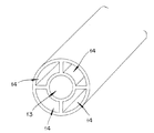
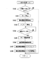
図1は本発明に係る加熱治療装置の概略構成図、図2は往チューブおよび復チューブの断面図、図3は往チューブおよび復チューブの変形例を示す図である。 FIG. 1 is a schematic configuration diagram of a heat treatment apparatus according to the present invention, FIG. 2 is a cross-sectional view of a forward tube and a return tube, and FIG. 3 is a view showing a modification of the forward tube and the return tube.
本発明に係る加熱治療装置は、アプリケータ1、レーザ光源装置2、フットスイッチ3、ディスプレイ装置4、貯蔵タンク5(貯蔵部)および制御本体6を有する。アプリケータ1、レーザ光源装置2、フットスイッチ3、ディスプレイ装置4および貯蔵タンク5は、いずれも制御本体6に接続されており、該制御本体6によりそれぞれの動作が制御されている。以下、各構成について説明する。
The heat treatment apparatus according to the present invention includes an
アプリケータ1は、生体内に挿入するための長尺状の挿入部11を有する。挿入部11には、先端内部にレーザ光を照射するレーザ照射部(図示せず)が設けられている。アプリケータ1は、レーザ照射部から側方の生体組織に向けてレーザ光を照射する。照射するレーザ光は、光ファイバ12を通じて、レーザ光源装置2から供給される。アプリケータ1は、レーザ光の照射によって、たとえば、前立腺肥大症や、各種の癌などの腫瘍の治療を行う。
The
レーザ光の発生により、レーザ照射部自体も加熱され、レーザ照射部に接触する生体表面も加熱される。しかし、レーザ照射部が高温になりすぎると故障する虞があり、また、生体表面の正常な組織まで加熱することは避けたい。そこで、挿入部11内には、レーザ照射部を通るように、冷却水が循環されている。 Due to the generation of the laser light, the laser irradiation unit itself is also heated, and the living body surface in contact with the laser irradiation unit is also heated. However, there is a risk of failure if the laser irradiation part becomes too hot, and it is desirable to avoid heating to normal tissue on the surface of the living body. Therefore, cooling water is circulated in the insertion portion 11 so as to pass through the laser irradiation portion.
アプリケータ1は、冷却水が循環されるように、冷却水が供給される往チューブ13と、冷却水が排出される復チューブ14とに接続されている。冷却水は、往チューブ13を通り、アプリケータ1を循環して、復チューブ14を通って戻る。これにより、挿入部11内のレーザ照射部自体が冷却されると共に、挿入部11に接触している生体表面が冷却される。往チューブ13および復チューブ14は、共に、後述する制御本体6に内蔵されている冷却装置に接続されている。往チューブ13および復チューブ14は、たとえば、図2に示すように、2本のチューブを並行に一体的に成形している。
The
また、往チューブ13および復チューブ14は、図3に示すように、1本のチューブ内に同軸形状として、内部に往チューブ13を形成し、外部に復チューブ14を形成してもよい。
Further, as shown in FIG. 3, the
アプリケータ1には、さらに、図示しないフラッシュルーメンが設けられている。フラッシュルーメンは、挿入部11内で、冷却水の循環通路から分岐して、挿入部11の先端まで形成されている通路である。フラッシュルーメンは、通常閉塞されている。挿入部11先端近傍におけるレーザの照射窓や、内視鏡観察窓を洗浄する際に、閉塞が解除され、挿入部11外部に向けて冷却液が噴出される。洗浄にも冷却液を用いるので、フラッシュ操作により、制御本体6内の冷却液は減少する。
The
レーザ光源装置2は、生体に照射するためのレーザ光を発生する。レーザ光源装置2は、たとえば、レーザ出力値、レーザパルス時間、レーザパルス間隔などの出力条件を、スイッチやダイヤルで設定できる。
The laser
レーザ光源装置2は、制御本体6を介して、フットスイッチ3に接続されている。術者がフットスイッチ3を踏み込んでいる間、レーザ光源装置2は、電源ONに制御され、レーザ光を発生する。これにより、術者が任意のタイミングおよび出力時間でレーザ光を病変部に照射できる。
The laser
フットスイッチ3は、術者の足元に置かれ、踏まれることによって制御本体6にレーザ光の照射を促すON、OFF信号を出力する。レーザ照射準備が完了しているときにフットスイッチ3を踏むとレーザ光源装置2はレーザ光を発生する。
The
ディスプレイ装置4は、制御本体6の上部に配置されている。ディスプレイ装置4は、術者に対して所定の情報を表示すると共に、所定の設定や操作を受け付けるユーザインタフェースである。ディスプレイ装置4は、タッチパネル方式を採用し、術者が画面に触れて操作可能となっている。
The
貯蔵タンク5は、内部に冷却水が貯蔵されており、制御本体6に内蔵されている冷却装置に冷却水を補充するための装置である。貯蔵する冷却水としては、滅菌水、滅菌蒸留水、または滅菌生理食塩水が用いられる。冷却水は、管状の補充チューブ51を介して、貯蔵タンク5から制御本体6に充填される。貯蔵タンク5は、底がゴムキャップにより塞がれている。また、補充チューブ51の貯蔵タンク側の先端は針状に形成されている。貯蔵タンク5を制御本体6に接続する際には、補充チューブ51の針状の先端を、貯蔵タンク5の底に差し込む。この構成により、貯蔵タンク5の接続、交換が簡単で、かつ、密封性が保たれる。
The
貯蔵タンク5は、内部が陰圧になった時に、大気圧によって変形可能な柔軟なバッグ形状のものが好ましい。また、仮に貯蔵タンク5がハードケースの場合には、通気孔を設けるのが好ましい。
The
制御本体6は、上述の通り、加熱治療装置の各構成と接続されており、フットスイッチ3から出力されるON、OFF信号などを用いて、加熱治療装置全体の動作を制御する。また、制御本体6は、貯蔵タンク5からの冷却水の充填も制御する。特に、本発明では、制御本体6は、貯蔵タンク5から冷却水を充填するにあたって、冷却水の枯渇や漏れなどの異常事態を検知し、これに対応する構成を特徴としている。
As described above, the control
したがって、以下では、制御本体6の詳細な構成を説明する。
Therefore, a detailed configuration of the
(制御本体)
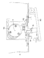
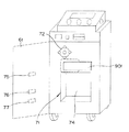
図4は制御本体を示す図である。
(Control body)
FIG. 4 is a diagram showing the control body.
制御本体6は、開閉式の扉61を有し、扉61で閉ざされた制御本体内部に冷却装置7が設けられている。
The control
扉61には、図示しない開閉検出センサが設けられている。扉61が開いているときには、冷却水の充填が行われない。
The
冷却装置7は、格納庫71と、ロータリポンプ72と、流量センサ73と、温度調節部74と、上限水位センサ75と、下限水位センサ76と、温度センサ77と、閉塞機構9とを有する。
The
格納庫71は、扉61が閉まったときに、所定の内部空間ができるように、制御本体6に設けられた凹部である。格納庫71は、冷却水の容器である冷却水バッグ8(図5参照)を格納する。冷却水バッグ8は、格納庫71内に設けられた取り付けピン(不図示)により、位置決めされ、取り付けられている。冷却水バッグ8からは、上述の往チューブ13および復チューブ14が延びている。冷却水バッグ8について、詳細は図5を参照しつつ後述する。
The
ロータリポンプ72は、格納庫71の上部に設けられている。ロータリポンプ72は、回転自在に取り付けられ、外周に球状部材が取り付けられている。ロータリポンプ72は回転しながら、冷却水バッグ8から延びる往チューブ13の一部を球状部材によりしごいて、チューブ内の冷却水がアプリケータ1に循環するための圧力を付与する。
The
流量センサ73は、たとえば近接センサ(フォトダイオード等)である。復チューブ14内に配置された、たとえば金属製の水車の回転を検出することにより、冷却水の流量を検出する。
The
温度調節部74は、格納庫71内に設けられている。冷却水バッグ8が格納庫71内に配置され、冷却水が充填されたときに、冷却水バッグ8と接触し、該冷却水バッグ8を冷却または加熱することにより、冷却水の温度を調節する。
The
温度調節部74は、ペルチェ素子からなる。ペルチェ素子とは、所定の方向に直流電流を流すことにより冷却でき、また、逆方向に直流電流を流すことにより加温できる素子である。ペルチェ素子に加える電力を変化させることによって、冷却力または加温力を変更することもできる。
The
上限水位センサ75は、扉61に設けられており、冷却水バッグ8内の冷却水量が所定の上限量以上かどうかを検出する。下限水位センサ76は、冷却水バッグ8内の冷却水量が所定の下限量以下かどうかを検出する。上限水位センサ75および下限水位センサ76は、共に、静電容量式近接センサである。これに限らず、水位を光学的に検出するものや、冷却水バッグ8内で水位を直接的に検出できるタイプのものでもよい。
The upper limit
温度センサ77は、扉61に設けられており、冷却水バッグ8と接触することにより、冷却水の温度を検出する。
The
閉塞機構9は、貯蔵タンク5および冷却水バッグ8を接続する上述の補充チューブ51を閉塞または開放する。これにより、貯蔵タンク5から冷却水バッグ8への冷却水の補填を制御する。
The
冷却水バッグ8および閉塞機構9について、より詳細に説明する。
The cooling
(冷却水バッグ)
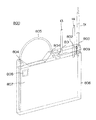
図5は冷却装置に取り付けられた冷却水バッグの様子を示す図である。
(Cooling water bag)
FIG. 5 is a view showing a state of the cooling water bag attached to the cooling device.
冷却水バッグ8は、図5に示すように、ハンガー部81と、バッグ部82とを有する。
As shown in FIG. 5, the cooling
ハンガー部81は、厚さ5mmのポリカーボネート等の硬質部材からなり、また、バッグ部82は、厚さ100μmのPET等の軟性部材からなる。
The
ハンガー部81には、冷却水バッグ8を格納庫71内に配置する際に、格納庫71内の取り付けピン(不図示)に引っ掛けられる穴部811と穴部812とが設けられている。穴部811と穴部812とは異なる形状を有しており、また、格納庫71内の取り付けピンも対応して異なる形状を有している。したがって、冷却水バッグ8は、格納庫71に対して一定の方向に取り付けられる。これにより、冷却水バッグ8から延びる往チューブ13および復チューブ14が、アプリケータ1に逆向きに取り付けられることがない。
The
またハンガー部81には、往チューブポート83、復チューブポート84、補充チューブポート85、およびエアベント86が設けられている。
In addition, the
往チューブポート83は、往チューブ13に接続されている。往チューブポート83は、冷却水バッグ8内の冷却水を吸いだす方なので、バッグ部82内の深くまで伸延している。往チューブ13には、ポンプチューブ131が設けられている。ポンプチューブ131は、冷却水バッグ8が格納庫71に取り付けられると、ロータリポンプ72に接触する。この状態で、図5に示すように、時計回りにロータリポンプ72を回転させることにより、ポンプチューブ131がしごかれ、ポンプチューブ131内の冷却水には、アプリケータ1に向かって循環する圧力が付与される。
The
復チューブポート84は、復チューブ14に接続されている。復チューブ14には、水車部141が設けられている。水車部141では、内部に、たとえば、金属製の水車が設けられている。この水車は、図4に示す流量センサ73により、回転数が検出可能である。流量センサ73によって、回転が検出され、該復チューブ14に流れる冷却水の流量が検出される。
The
補充チューブポート85は、補充チューブ51に接続されている。補充チューブ51は、部位511において、後述する閉塞機構に保持され、閉塞または開放される。エアベント86は、冷却水バッグ8内の冷却水は通過させることなく、空気のみを通過できるフィルタである。
The
バッグ部82は、シートを2枚張り合わせて内部を中空にして形成されている。バッグ部82は、ハンガー部81の下に接着されている。このため、ハンガー部81が格納庫71内に取り付けられれば、バッグ部82は、自然と所定の位置に位置決めされる。所定の位置とは、冷却水バッグ8に冷却水が充填された際に、扉61を閉めると、自動的にバッグ部82の広い表面が温度調節部74と密着し、さらに、扉61内側の上限水位センサ75と、下限水位センサ76と、温度センサ77とも密着する位置である。
The
なお、バッグ部82は、上述の通り、軟性部材から形成されている。したがって、冷却水充填前は萎んでいるが、冷却水が充填されるに従って広がるので、充填時には、温度調節部74等と密着する。
In addition, the
(閉塞機構)
図6は開放状態の閉塞機構を示す図、図7は閉塞状態の閉塞機構を示す図である。なお、図6および図7では、閉塞機構9を平面方向から見ている。補充チューブ51については、断面を示している。
(Occlusion mechanism)
FIG. 6 is a view showing the closing mechanism in the open state, and FIG. 7 is a view showing the closing mechanism in the closed state. 6 and 7, the
閉塞機構9は、小扉90、固定片91、可動片92、ロータリーソレノイド93、押え片94を含む。
The
小扉90は、制御本体6に開閉自在に取り付けられている。小扉90を開けると、制御本体6には、切り欠きが設けられており、固定片91および可動片92が突出している。
The
固定片91および可動片92は、互いに向かって幅が小さくなるように形成されている。図6に示すように、可動片92が動いていない状態では、固定片91および可動片92の間が略V字型となる。冷却水バッグ8が冷却装置7に取り付けられると、補充チューブ51が固定片91および可動片92の中央、すなわちV字の底に位置する。
The fixed
可動片92は、ロータリーソレノイド93に取り付けられており、ロータリーソレノイド93の弾性力によって、固定片91に突き当たる方向(図6中では時計回り)に常に付勢されている。
The
ロータリーソレノイド93は、通電による内部のコイルと永久磁石との間に吸引・反発力を利用し、軸Aを中心として回転可能である。
The
押え片94は、小扉90の内側に取り付けられており、先端が滑らかに窪んでいる。押え片94は、小扉90を閉めると、先端の窪みに補充チューブ51を引っ掛け、固定片91および可動片92側に補充チューブ51を押す。押された補充チューブ51は、固定片91および可動片92の隙間に入っていく。ここで、可動片92は、図7に示すように、補充チューブ51の移動に伴って、ロータリーソレノイド93の弾性力に逆らいながら、軸Aを中心に反時計回りに回転する。
The
小扉90が完全に閉まった状態では、補充チューブ51は、固定片91および可動片92の間に挟まれ、ロータリーソレノイド93の弾性力が付勢されるので、図7に示すように断面楕円状につぶされ、通路が閉塞される。
In a state where the
閉塞機構9により閉塞された補充チューブ51の閉塞を解除するには、ロータリーソレノイド93に通電する。通電により、ロータリーソレノイド93が弾性力とは反対向きに回転され、すなわち、可動片92が固定片91から離れる方向に移動する。これにより、固定片91および可動片92の間隔が広くなり、補充チューブ51の断面形状が元に戻る。したがって、補充チューブ51に冷却水が通過できるようになる。
In order to release the blockage of the refilling
このように、ロータリーソレノイド93に通電すれば、補充チューブ51の閉塞を解除でき、通電を止めれば閉塞できる。補充チューブ51は、貯蔵タンク5から冷却水バッグ8に冷却水を充填する際には閉塞が解除され、充填を中止する際には閉塞される。
In this way, if the
なお、固定片91と可動片92とでは、対向する直線部分の長さが、可動片92の方が長い。したがって、補充チューブ51が、固定片91と可動片92の間に押し込まれ始めるときには、固定片91の直線部分よりも先に可動片92の直線部分に接触する。これにより、補充チューブ51の押し込み力は可動片92が回転しやすいように作用する。
In the fixed
次に、制御本体6の内部構成をブロック図で示し、説明する。
Next, the internal configuration of the
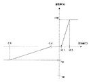
図8は制御本体6の内部構成を示すブロック図、図9は目標駆動率テーブルを示す図、図10は駆動率制限テーブルを示す図である。
FIG. 8 is a block diagram showing an internal configuration of the
図8に示すように、上述の構成のほかに、制御本体6内には、制御部62、充填タイマ63、総充填タイマ64、ポンプ駆動タイマ65、目標駆動率テーブル66、駆動率制限テーブル67、および温度調節部駆動タイマ68を有する。充填タイマ63、総充填タイマ64、ポンプ駆動タイマ65、目標駆動率テーブル66、駆動率制限テーブル67、および温度調節部駆動タイマ68は、いずれも、制御部62に接続されている。
As shown in FIG. 8, in addition to the configuration described above, the
制御部62は、加熱治療装置の各構成と接続されており、加熱治療装置全体の動作を統括的に制御する。制御部62は、上限水位センサ75、下限水位センサ76および温度センサ77からの検出信号を受信して、冷却装置7および閉塞機構9を制御する。
The
充填タイマ63は、閉塞機構9が開放している時間、すなわち、冷却水が貯蔵タンク5から冷却水バッグ8に充填されている時間を、制御部62を介して計測する。
The filling
総充填タイマ64は、1回の治療を通じて、閉塞機構9が開放されている合計時間を、制御部62を介して計測する。
The
ポンプ駆動タイマ65は、ロータリポンプ72が駆動開始してからの時間を、制御部62を介して計測する。
The
目標駆動率テーブル66は、測定温度と目標温度(所定の設定温度)との差分値と、温度調節部74に印加する電力強度との関係を示すテーブルであり、図9に示される。図9において、横軸に示す差分値は、温度センサ77による冷却水の測定温度から所定の設定温度を引いた値である。縦軸に示す駆動率は、温度調節部74を最大出力の何%で駆動するかを示す値である。ここで、駆動率が+100%であれば、温度調節部74を100%駆動し冷却することを示し、電力強度が−50%であれば、温度調節部74を50%で駆動し加温することを示す。冷却するか加温するかは、電流を流す向きで調節し、何%の駆動率で駆動するかは流す電流の大きさで調節できる。
The target drive rate table 66 is a table showing the relationship between the difference value between the measured temperature and the target temperature (predetermined set temperature) and the power intensity applied to the
図9によれば、本実施形態では、差分値が+0.1℃以上で冷却が開始され、+0.5度以上では100%駆動で冷却し、また、差分値が−0.4℃以下で加温が開始され、−2.4度以下になると、50%駆動で加温する設定になっている。 According to FIG. 9, in this embodiment, cooling is started when the difference value is + 0.1 ° C. or more, cooling is performed by 100% driving at + 0.5 ° C. or more, and the difference value is −0.4 ° C. or less. When the heating is started and becomes −2.4 degrees or less, the heating is set to 50% driving.
駆動率制限テーブル67は、温度調節部駆動タイマ68の計測値と、温度調節部74の最大駆動率との関係を示すテーブルであり、図10に示される。図10において、横軸に示す計測値は、温度調節部74が駆動を開始してからの経過時間(秒)を示す値である。縦軸に示す最大駆動率は、温度調節部74を最大出力の何%で駆動するかを示す値である。
The drive rate restriction table 67 is a table showing the relationship between the measured value of the temperature adjustment
温度調節駆動タイマ68は、温度調節部74が駆動を開始してからの時間を計測する。
The temperature
上記目標駆動率テーブル66、駆動率制限テーブル67、温度調節部駆動タイマ68の計測値がどのように参照されて、温度調節の制御が行われるかを、例を挙げて説明する。
An example of how temperature adjustment control is performed by referring to the measurement values of the target drive rate table 66, the drive rate limit table 67, and the temperature adjustment
たとえば、冷却水の設定温度が22℃であり、現在の冷却水の測定温度が23℃である場合、図9の目標駆動率テーブル66が参照されて、設定温度と測定温度との差分値が+1℃である。したがって、目標駆動率は、+100%、すなわち、100%の駆動率で冷却水を冷却することが決定される。 For example, when the set temperature of the cooling water is 22 ° C. and the current measured temperature of the cooling water is 23 ° C., the target drive rate table 66 of FIG. 9 is referred to, and the difference value between the set temperature and the measured temperature is + 1 ° C. Therefore, the target drive rate is determined to cool the cooling water at + 100%, that is, 100% drive rate.
ここで、さらに、温度調節部駆動タイマ68の計測時間に基づいて、図10の駆動率制限テーブル67が参照される。すなわち、いきなり温度調節部74の駆動率を100%で駆動し、冷却するのではなく、温度調節部駆動タイマ68の計測時間に基づいて徐々に駆動率を上げていく。駆動を開始してから、5秒後には、駆動率を50%とし、9秒後以降は100%とする。これにより、急激な冷却水の冷却を防止する。
Here, the drive rate restriction table 67 of FIG. 10 is referred to based on the measurement time of the temperature adjustment
なお、図9の目標駆動率テーブル66に基づいて、たとえば、目標駆動率が50%に決定された場合、温度調節部74の駆動時間が5秒を経過した後は、そのまま、温度調節部74の駆動率が50%に維持される。冷却水の温度が設定温度に到達したら、温度調節部74の駆動が停止される。
For example, when the target drive rate is determined to be 50% based on the target drive rate table 66 of FIG. 9, after the drive time of the
逆に、温度調節部74が停止する場合は、温度調節部駆動タイマ68は減算され、温度調節部74の駆動率が徐々に低下され、最終的に0%とされて停止する。
On the other hand, when the
このように、温度調節部74の冷却および加温を段階的に調節することによって、急激な温度変化を抑え、温度調節部74に用いているペルチェ素子の劣化を防止できる。
Thus, by adjusting the cooling and heating of the
(作用)
以上、本発明の加熱治療装置の構成について説明してきた。以下では、上記構成の加熱治療装置がどのように作用するかについて、前立腺治療を行う際の加熱治療装置の動作を例として説明する。冷却水バッグ8はすでに冷却装置7に取り付けられているものとする。
(Function)
The configuration of the heat treatment apparatus of the present invention has been described above. In the following, how the heat treatment apparatus having the above configuration works will be described by taking the operation of the heat treatment apparatus when performing prostate treatment as an example. It is assumed that the cooling
加熱治療装置では、まず、充填モードとして、治療開始前に、貯蔵タンク5を補充チューブ51に取り付けて、貯蔵タンク5から冷却水バッグ8に冷却水を充填して、その後、治療モードとして、アプリケータ1を体内に挿入して加熱治療を開始する。以下では、充填モードと、治療モードの場合に分けて、加熱治療装置の作用を説明する。加熱治療装置の動作は、上述の制御部62により制御されている。
In the heat treatment apparatus, first, as a filling mode, the
<充填モード>
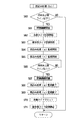
図11は充填モードの加熱治療装置の動作の流れを示すフローチャートである。
<Filling mode>
FIG. 11 is a flowchart showing an operation flow of the heat treatment apparatus in the filling mode.
充填モードでは、レーザ照射の際の尿道表面冷却用の冷却水を、冷却装置7内の冷却水バッグ8に充填する。
In the filling mode, the cooling water for cooling the urethra surface at the time of laser irradiation is filled in the cooling
最初に、閉塞機構9において、補充チューブ51の部位511における閉塞が開放される(ステップS1)。これにより、補充チューブ51を冷却水が通過可能となり、冷却水バッグ8よりも高位置にある貯蔵タンク5から自然落下により冷却水が冷却水バッグ8に充填される。
First, in the
ここで、総充填タイマ64の計測が開始される(ステップS2)。同時に、割込み処理(a)を行うかどうかの監視が開始される(ステップS3)。この監視は、制御部62により行われる。割込み処理(a)に移行する場合については、後述する。
Here, measurement of the
下限水位センサ76の検出に基づいて、冷却水が冷却水バッグ8の下限以上まで充填されたかどうかが判断される(ステップS4)。冷却水がまだ下限以上まで充填されていない場合(ステップS4:NO)は、下限水位センサ76の検出を続行する。
Based on the detection by the lower limit
冷却水が下限以上まで充填された場合(ステップS4:YES)、温度調節部74の駆動が開始され(ステップS5)、同時に温度調節部駆動タイマ68の計測が開始される(ステップS6)。ここでは、上述の通り、図9の目標駆動率テーブル66、図10の駆動率制限テーブル67、および温度調節部駆動タイマ68の計測時間が参照されつつ、冷却水の温度が調節される。
When the cooling water is filled up to the lower limit or more (step S4: YES), driving of the
そして、上限水位センサ75の検出に基づいて、冷却水が冷却水バッグ8の上限まで、すなわち冷却水バッグ8が満杯になったかどうかが判断される(ステップS7)。冷却水が満杯になっていない場合(ステップS7:NO)、引き続き冷却水の充填を続ける。
Based on the detection by the upper limit
冷却水が満杯になっている場合(ステップS:YES)、割込み処理(a)の監視が終了され(ステップS8)、閉塞機構9により補充チューブ51が閉塞される(ステップS9)。これにより、冷却水バッグ8への冷却水の充填が中止される。同時に、総充填タイマ64の計測を一時停止される(ステップS10)。これまでの総充填タイマ64の計測結果は維持される。
When the cooling water is full (step S: YES), the monitoring of the interruption process (a) is ended (step S8), and the refilling
割込み処理(a)
上記充填モードにおけるステップS3〜ステップS8までに実行されうる割込み処理(a)について説明する。
Interrupt processing (a)
The interrupt process (a) that can be executed from step S3 to step S8 in the filling mode will be described.
図12は、割込み処理(a)の際の加熱治療装置の動作の流れを示すフローチャートである。 FIG. 12 is a flowchart showing an operation flow of the heat treatment apparatus during the interruption process (a).
総充填タイマ64の計測時間が一定時間(たとえば、300秒)を超過したかどうかが判断され(ステップS40)、300秒を超過した場合(ステップS40:YES)には、実質的に割込み処理(a)に移行する。300秒を経過していない場合(ステップS40:NO)には、割込み処理(a)はされず、充填モードが継続される。
It is determined whether or not the measurement time of the
割込み処理(a)に移行すると、閉塞機構9により、補充チューブ51が閉塞される(ステップS41)。ロータリポンプ72が作動している場合には、ロータリポンプ72の駆動が停止され(ステップS42)、温度調節部74の駆動も停止される(ステップS43)。
When the interruption process (a) is entered, the
そして、ディスプレイ装置4にメッセージが表示される(ステップS44)。表示されるメッセージは、たとえば、「貯蔵タンクの残量を確認してください」、「補充チューブの抜けまたは破れがないか確認してください」、「冷却水バッグが破れていないか確認してください」などである。 Then, a message is displayed on the display device 4 (step S44). The displayed messages are, for example, “Check the remaining capacity of the storage tank”, “Check that the refill tube is not pulled out or torn”, “Check that the cooling water bag is not torn. And so on.
制御部62は、ディスプレイ装置4に表示される確認ボタンが押されたかどうかを判断し(ステップS45)、確認ボタンが押されるまで待機する。確認ボタンが押されると(ステップS45:YES)、再度、<充填モード>に戻るべく、閉塞機構9が開放される(ステップS46)。必要であれば、ロータリポンプ72の駆動が再開される(ステップS47)。温度調節部74の駆動も再開される(ステップS48)。
The
そして、温度調節部駆動タイマ68が一度リセットされてから(ステップS49)、再度計測が開始される(ステップS50)。
Then, after the temperature adjustment
なお、通常、<充填モード>から割込み処理(a)に移行した場合には、ロータリポンプ72は駆動されていない。しかし、割込み処理(a)は、後述する割込み処理(b)からも移行することがあるので、ロータリポンプ72の駆動について、ステップS42およびステップS47が設けられている。
Normally, the
以上のように、<充填モード>では、冷却水バッグ8に冷却水を充填している間、総充填タイマ64に基づいて所定時間(たとえば、300秒)が経過したかどうかを監視し、経過している場合には、異常と判断して、警告のメッセージを表示する。したがって、補充チューブ51の抜けまたは破れや、冷却水バッグ8の破れが発生している可能性を検出して、術者に知らせることができる。
As described above, in the <filling mode>, while the cooling
<治療モード>
次に治療モードについて説明する。
<Treatment mode>
Next, the treatment mode will be described.
図13は、治療モードの加熱治療装置の動作の流れを示すフローチャートである。 FIG. 13 is a flowchart showing an operation flow of the heat treatment apparatus in the treatment mode.
上記<充填モード>が終了した後に、手術を行う際の工程が<治療モード>である。 After the above <filling mode> is completed, a step when performing an operation is <treatment mode>.
まず、術者の指示によりロータリポンプ72の駆動が開始され(ステップS21)、ポンプ駆動タイマ65による時間の計測が開始される(ステップS22)。また、割込み処理(b)に移行するかどうかの監視も開始される(ステップS23)。割込み処理(b)に移行した場合の処理については、後述する。
First, the drive of the
ポンプ駆動タイマ65による計測時間が30秒を経過したかどうかが判断される(ステップS24)。ポンプ駆動タイマ65の計測時間が30秒を経過していない場合(ステップS24:NO)、経過するまで待機する。
It is determined whether the measurement time by the
計測時間が30秒を経過すると(ステップS24:YES)、ポンプ駆動タイマ65がリセットされ(ステップS25)、流量センサ73による冷却水の流量の検出が開始される(ステップS26)。続けて、割込み処理(d)に移行するか否かの監視が開始される(ステップS27)。
When the measurement time has passed 30 seconds (step S24: YES), the
術者によって、フットスイッチ3が踏まれ、レーザ光の照射が開始される(ステップS28)。治療が終了するまでレーザ光の照射が連続的または断続的に行われる。治療が終了すると(ステップS29:YES)、割込み処理(d)に移行するかどうかの監視が終了され(ステップS30)、流量センサ73による検出も停止される(ステップS31)。
The surgeon steps on the
さらに、割込み処理(b)に移行するかどうかの監視が終了され(ステップS32)、ロータリポンプ72の駆動が停止され(ステップS33)、温度調節部74の駆動が停止される(ステップS34)。
Further, the monitoring of whether or not to proceed to the interrupt process (b) is finished (step S32), the drive of the
上記<治療モード>におけるステップS23〜ステップS32までに実行されうる割込み処理(b)について説明する。 The interrupt process (b) that can be executed from step S23 to step S32 in the <treatment mode> will be described.
割込み処理(b)
図14は、割込み処理(b)の際の加熱治療装置の動作の流れを示すフローチャートである。
Interrupt processing (b)
FIG. 14 is a flowchart showing an operation flow of the heat treatment apparatus during the interruption process (b).
上限水位センサ75の検出に基づいて、冷却水バッグ8内の冷却水が上限以下になったかどうかが判断され(ステップS60)、上限以下になった場合(ステップS60:YES)には、実質的に割込み処理(b)に移行する。冷却水が上限以下になっていない場合(ステップS60:NO)には、割込み処理(b)はされず、<治療モード>が継続される。
Based on the detection by the upper limit
割込み処理(b)に移行すると、閉塞機構9により、補充チューブ51が開放される(ステップS61)。これにより、冷却水バッグ8への冷却水の充填が始まる。これと同時に、充填タイマ63による計測が0から開始され(ステップS62)、また、総充填タイマ64による計測が停止した状態から再開される(ステップS63)。ここで、さらに、割込み処理(a)に移行するかどうか、および割込み処理(c)に移行するかどうかの監視が開始される(ステップS64、ステップS65)。
When the interruption process (b) is entered, the
そして、冷却水の充填により、冷却水が上限以上になったかどうかが判断され(ステップS66)、上限以上になるまで待機される。上限以上になると(ステップS66:YES)、冷却水は十分に充填されているので、閉塞機構9により、補充チューブ51が閉塞される(ステップS67)。
Then, it is determined whether or not the cooling water has exceeded the upper limit due to the filling of the cooling water (step S66), and the system waits until it reaches the upper limit or more. When the upper limit is exceeded (step S66: YES), the
ここで、割込み処理(a)、割込み処理(c)の監視が終了する(ステップS68、ステップS69)。充填タイマ63がリセットされ(ステップS70)、総充填タイマ64の計測が一時停止される(ステップS71)。
Here, the monitoring of the interrupt process (a) and the interrupt process (c) ends (steps S68 and S69). The filling
以上のように、本発明では、<治療モード>の途中でも、冷却水が少なくなると、割込み処理(b)により自動的に冷却水が充填されるようになっている。 As described above, in the present invention, the cooling water is automatically filled by the interruption process (b) when the cooling water is reduced even during the <treatment mode>.
上記割込み処理(b)の途中においても、さらに、割込み処理(a)および割込み処理(c)に移行する場合がある。割込み処理(a)は、上記割込み処理(b)におけるステップS64〜ステップS68までに実行される。割込み処理(a)への移行条件および処理内容は、上述したので、その説明を省略する。割込み処理(c)について説明する。 Even in the middle of the interrupt process (b), the process may further shift to the interrupt process (a) and the interrupt process (c). The interrupt process (a) is executed from step S64 to step S68 in the interrupt process (b). Since the transition condition to interrupt processing (a) and the processing contents have been described above, the description thereof will be omitted. The interrupt process (c) will be described.
割込み処理(c)
割込み処理(c)は、上記割込み処理(b)におけるステップS65〜ステップS69までに実行されうる。
Interrupt processing (c)
The interrupt process (c) can be executed from step S65 to step S69 in the interrupt process (b).
図15は、割込み処理(c)の際の加熱治療装置の動作の流れを示すフローチャートである。 FIG. 15 is a flowchart showing an operation flow of the heat treatment apparatus during the interruption process (c).
割込み処理(b)のステップS62で開始した充填タイマ63の計測時間が20秒を経過したかどうかが判断され(ステップS80)、20秒以上経過した場合(ステップS80:YES)には、実質的に割込み処理(c)に移行する。20秒経過していない場合(ステップS80:NO)には、割込み処理(b)が継続される。
It is determined whether or not the measurement time of the filling
割込み処理(c)に移行すると、閉塞機構9により、補充チューブ51が閉塞される(ステップS81)。これにより、冷却水バッグ8への冷却水の充填が停止される。ロータリポンプ72の駆動が停止され(ステップS82)、温度調節部74の駆動も停止される(ステップS83)。
When the interruption process (c) is entered, the
そして、ディスプレイ装置4にメッセージが表示される(ステップS84)。表示されるメッセージは、たとえば、「補充チューブの抜けまたは破れがないか確認してください」、「冷却水バッグが破れていないか確認してください」などである。 Then, a message is displayed on the display device 4 (step S84). The displayed message is, for example, “Check if the refill tube is not pulled out or torn”, “Check if the cooling water bag is not torn”, or the like.
制御部62は、ディスプレイ装置4に表示される確認ボタンが押されたかどうかを判断し(ステップS85)、確認ボタンが押されるまで待機する。確認ボタンが押されると(ステップS85:YES)、割込み処理(b)に戻るべく、閉塞機構9が開放される(ステップS86)。ロータリポンプ72の駆動が再開される(ステップS87)。温度調節部74の駆動も再開される(ステップS88)。
The
そして、温度調節部駆動タイマ68が一度リセットされてから(ステップS89)、再度計測が開始される(ステップS90)。
Then, after the temperature adjustment
以上のように、割込み処理(b)では、充填タイマ63により、冷却水を冷却水バッグ8に充填する時間を計測し、所定時間(たとえば、20秒)より長いときに異常と判断して、ディスプレイ装置4に警告のメッセージを表示する。したがって、補充チューブ51の抜けまたは破れや、冷却水バッグ8の破れが発生している可能性を検出して、術者に知らせることができる。
As described above, in the interruption process (b), the filling
上記<治療モード>におけるステップS27〜ステップS30までに実行されうる割込み処理(d)について説明する。 The interrupt process (d) that can be executed from step S27 to step S30 in the <treatment mode> will be described.
割込み処理(d)
図16は、割込み処理(d)の際の加熱治療装置の動作の流れを示すフローチャートである。
Interrupt processing (d)
FIG. 16 is a flowchart showing an operation flow of the heat treatment apparatus during the interruption process (d).
<治療モード>のステップS26で開始した流量センサ73による計測に基づいて、アプリケータ1と冷却水バッグ8との間を循環中の冷却水の流量が、所定の流量(たとえば、100ml/分)以下かどうかが判断され(ステップS100)、所定の流量以下である場合(ステップS100:YES)、実質的に割込み処理(d)に移行する。所定の流量以上である場合(ステップS100:NO)には、<治療モード>が続行される。
Based on the measurement by the
割込み処理(d)に移行すると、ロータリポンプ72の駆動が停止され(ステップS101)、温度調節部74の駆動が停止される(ステップS102)。
When the interruption process (d) is entered, the driving of the
そして、ディスプレイ装置4にメッセージが表示される(ステップS103)。表示されるメッセージは、たとえば、「往チューブまたは復チューブの水漏れを確認してください」、「往チューブまたは復チューブの折れ/詰まりを確認してください」などである。 Then, a message is displayed on the display device 4 (step S103). The displayed message is, for example, “Check for water leakage in the forward tube or the return tube”, “Check for breakage / clogging of the forward tube or the return tube”, etc.
制御部62は、ディスプレイ装置4に表示される確認ボタンが押されたかどうかを判断し(ステップS104)、確認ボタンが押されるまで待機する。確認ボタンが押されると(ステップS104:YES)、<治療モード>に戻るべく、ロータリポンプ72の駆動が再開される(ステップS105)。温度調節部74の駆動も再開される(ステップS106)。
The
そして、温度調節部駆動タイマ68が一度リセットされてから(ステップS107)、再度計測が開始される(ステップS108)。
Then, after the temperature adjustment
以上のように、割込み処理(d)では、流量センサ73により、循環する冷却水の流量を計測し、所定の流量よりも少ないときに異常と判断して、ディスプレイ装置4に警告のメッセージを表示する。したがって、往チューブ13または復チューブ14の水漏れ、折れ、詰まり等が発生している可能性を検出して、術者に知らせることができる。
As described above, in the interrupt process (d), the flow rate of the circulating cooling water is measured by the
なお、<治療モード>では、ロータリポンプ72の駆動開始30秒後から、流量センサ73により流量を検出している。これは、ロータリポンプ72は、往チューブ13に設けられ、流量センサ73は復チューブ14に設けられているからである。すなわち、ロータリポンプ72の駆動直後には、復チューブ14の流量センサ73近傍までは冷却水が到達しておらず、到達までにタイムラグがあるからである。
In the <treatment mode>, the flow rate is detected by the
タイムラグ分(たとえば、30秒)だけ、流量センサ73の検出を遅らせることによって、往チューブ13および復チューブ14に詰まり等が発生していなくても、発生していると誤って判断されるのを防止できる。このタイムラグ分の補正は、往チューブ13および復チューブ14の長さに応じて適宜変更される。
By delaying detection of the
以上のように、本発明では、充填モードおよび<治療モード>の最中にも、割込み処理(a)〜(d)に移行するかどうかを判断し、適宜移行するので、水漏れ等の可能性を早期に発見し、術者に知らせることができる。 As described above, in the present invention, it is determined whether or not to proceed to the interrupt processing (a) to (d) even during the filling mode and the <treatment mode>, and since the transition is made appropriately, water leakage or the like is possible. It is possible to detect sex early and inform the surgeon.
なお、上記実施形態における各構成については、当業者が適宜改変可能である。たとえば、以下のようないくつかの変形例が考えられる。 In addition, about the structure in the said embodiment, those skilled in the art can change suitably. For example, several modifications as follows can be considered.
(変形例1)
冷却水バッグの変形例
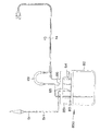
上記実施形態では、冷却水を充填する容器として、充填することで膨らむ冷却水バッグ8を用いている。しかし、膨らんだり縮んだりせずに、予め形状が固定された冷却水カセットを用いることもできる。
(Modification 1)
Modification of Cooling Water Bag In the above embodiment, the cooling
図17は、冷却水カセットを示す図である。 FIG. 17 is a diagram illustrating a cooling water cassette.
冷却水カセット800は、略全体がポリカーボネート等の硬質部材からなる。冷却水カセット800の上部には、往チューブポート801、復チューブポート802、補充チューブポート803およびポンプチューブポート804が設けられている。
The cooling
往チューブポート801には往チューブ13が接続され、復チューブポート802には復チューブ14が接続され、さらに、補充チューブポート803には補充チューブ51が接続されている。
The
ポンプチューブポート804の先端には、ポンプチューブ805が取り付けられている。ポンプチューブ805は、冷却水カセット800を冷却装置7に取り付けたときに、ロータリポンプ72によりしごかれる。
A
また、冷却水カセット800の下部には、冷却水が貯留されるタンク部806が設けられている。タンク部806は、表面積が大きな側面のうち片側に、フィルム部807が設けられている。フィルム部807は、硬質部材ではなく、フィルム材から形成されている。冷却カセット800を冷却装置7に取り付ける際には、フィルム部807が温度調節部74と密着される。密着させることにより、温度調節部74の温度を効率よく冷却水に伝達できる。
In addition, a
タンク部806の上部には、エアフィルタ808が設けられている。エアフィルタ808は、タンク部806内の空気だけを通過させるフィルタである。
An
また冷却カセット800は、ポンプチューブポート804と、往チューブポート801との間に、水車部809が設けられている。水車部809の内部構成は、上記実施形態の水車部141と同様である。
In addition, the cooling
冷却水カセット800を冷却装置7に取り付けると、ポンプチューブ805はロータリチューブ131と接触する位置に、水車部809は流量センサ73により検出可能な位置に、それぞれ自然と位置決めされる。
When the cooling
以上のように、変形例1では、水車部809が内蔵され、冷却水カセット800を冷却装置7に取り付けると、自然と、水車部809が流量センサ73の検出可能位置に位置決めされるので、取り付け作業に手間がかからず、効率的に治療を行える。
As described above, in the first modification, when the
(変形例2)
冷却水バッグの変形例2
図18は、冷却水バッグのさらなる変形例を示す図である。
(Modification 2)
FIG. 18 is a view showing a further modification of the cooling water bag.
図18に示す冷却水バッグ850は、上記実施形態の冷却水バッグ8と比較して、ハンガー部851が各チューブを保持するホルダーの役割も果たす点で異なる。
The cooling
変形例2における冷却水バッグ850では、図18に示すように、ハンガー部851に、往チューブ13、復チューブ14、補充チューブ51およびエアベント86が挿通されている。これにより、これらのチューブが垂れ下がることなく、保持されている。
In the cooling
この構成を採用することにより、冷却水バッグ850を冷却装置7に取り付ける際に、チューブ類を把持して立たせておく必要がなく、容易に取り付けられる。
By adopting this configuration, when the cooling
(変形例3)
閉塞機構の変形例
図19は制御本体を示す図、図20は閉塞機構を示す図である。
(Modification 3)
FIG. 19 is a diagram showing a control main body, and FIG. 20 is a diagram showing a closing mechanism.
図19に示すように、変形例3では、閉塞機構9の小扉901が、上記実施形態に比較して図中右側に長くなっており、流量センサ73を覆うようになっている。小扉901の内面には、水車部押さえ片902が設けられている。水車部押さえ片902は、小扉901が閉まった状態において、流量センサ73と対向する位置に設けられている。
As shown in FIG. 19, in
このように水車部押さえ片902を設けることによって、冷却水バッグ8を冷却装置7に取り付け、小扉901を閉じると、水車部141が水車部押さえ片902に押される。したがって、水車部141が、自動的に確実に流量センサ73に取り付けられる。
By providing the water wheel
「付記」
(付記項1)
前記冷却水バッグ内の冷却水量が一旦所定量以上になった後に、該所定量より少なくなった場合、前記貯蔵タンクから前記冷却水バッグに前記冷却水が充填されている一回の充填時間を計測する充填時間計測タイマと、
前記充填時間が所定時間以上になった場合に異常を通知する異常通知手段と、
をさらに有する請求項1に記載の加熱治療装置。
"Appendix"
(Additional item 1)
When the amount of cooling water in the cooling water bag once exceeds a predetermined amount and then becomes less than the predetermined amount, a single filling time for filling the cooling water bag from the storage tank with the cooling water is set. A filling time measuring timer to measure,
An abnormality notification means for notifying an abnormality when the filling time is equal to or longer than a predetermined time;
The heat treatment apparatus according to
1…アプリケータ、
2…レーザ光源装置、
3…フットスイッチ、
4…ディスプレイ装置、
5…貯蔵タンク、
6…制御本体、
7…冷却装置、
8…冷却水バッグ、
9…閉塞機構、
11…挿入部、
12…光ファイバ、
13…往チューブ、
14…復チューブ、
51…補充チューブ、
61…扉、
62…制御部、
63…充填タイマ、
64…総充填タイマ、
65…ポンプ駆動タイマ、
66…目標駆動率テーブル、
67…駆動率制限テーブル、
68…温度調節駆動タイマ、
68…温度調節部駆動タイマ、
71…格納庫、
72…ロータリチューブ、
72…ロータリポンプ、
73…流量センサ、
74…温度調節部、
74…度調節部、
75…上限センサ、
75…上限水位センサ、
76…下限水位センサ、
77…温度センサ、
81…ハンガー部、
82…バッグ部、
83…往チューブポート、
84…復チューブポート、
85…補充チューブポート、
86…エアベント、
90…小扉、
91…固定片、
92…可動片、
93…ロータリーソレノイド、
94…押さえ片、
131…ポンプチューブ、
141…水車部、
511…部位、
800…冷却水カセット、
801…往チューブポート、
802…復チューブポート、
803…補充チューブポート、
804…ポンプチューブポート、
805…ポンプチューブ、
806…タンク部、
807…フィルム部、
808…エアフィルタ、
809…水車部、
850…冷却水バッグ。
1 ... applicator,
2 ... Laser light source device,
3 ... Foot switch,
4 ... display device,
5 ... Storage tank,
6 ... Control body,
7 ... Cooling device,
8 ... Cooling water bag,
9: Occlusion mechanism,
11 ... Insertion part,
12: optical fiber,
13 ... Out tube,
14 ...
51. Refill tube,
61 ... door,
62 ... control unit,
63 ... Filling timer,
64: Total filling timer,
65 ... pump drive timer,
66 ... target drive rate table,
67 ... Driving rate limit table,
68 ... Temperature control drive timer,
68 ... Temperature controller drive timer,
71 ... Hangar,
72. Rotary tube,
72 ... Rotary pump,
73 ... Flow sensor
74 ... temperature control unit,
74. Degree adjustment unit,
75: Upper limit sensor,
75: Upper water level sensor,
76 ... lower limit water level sensor,
77 ... Temperature sensor,
81 ... hanger part,
82 ... Bag part,
83 ... Out tube port,
84 ... Return tube port,
85 ... Refill tube port,
86 ... Air vent,
90 ... small door,
91 ... a fixed piece,
92 ... movable piece,
93 ... Rotary solenoid,
94 ... holding piece,
131 ... pump tube,
141 ... watermill,
511 ... site,
800 ... cooling water cassette,
801 ... Out tube port,
802 ... Return tube port,
803 ... refill tube port,
804 ... pump tube port,
805 ... pump tube,
806 ... tank part,
807 ... Film part,
808 ... an air filter,
809 ... turbine section,
850 ... Cooling water bag.
Claims (9)
前記エネルギーが照射されている生体表面および前記アプリケータを冷却するために、前記アプリケータに循環させる冷却水を貯留する冷却水容器と、
前記冷却水容器に充填するための前記冷却水を貯蔵する貯蔵部と、
前記冷却水容器内に貯留されている前記冷却水の量が所定量以上か否かを検出する上限センサと、
前記冷却水容器内の冷却水の量が前記所定量より少ない場合、前記貯蔵部から前記冷却水容器へ前記冷却水を充填させる充填制御手段と、
前記貯蔵部から前記冷却水容器に前記冷却水が充填されている総充填時間を計測する総充填時間計測タイマと、
前記総充填時間が所定時間以上になった場合に異常を通知する異常通知手段と、
を有することを特徴とする加熱治療装置。 In a heat treatment apparatus for performing heat treatment by inserting an applicator into a living body and irradiating energy to the living tissue from the applicator,
A cooling water container for storing cooling water to be circulated through the applicator in order to cool the living body surface irradiated with the energy and the applicator;
A storage unit for storing the cooling water for filling the cooling water container;
An upper limit sensor for detecting whether or not the amount of the cooling water stored in the cooling water container is a predetermined amount or more;
When the amount of cooling water in the cooling water container is less than the predetermined amount, filling control means for filling the cooling water container from the storage unit to the cooling water container,
A total filling time measuring timer for measuring a total filling time in which the cooling water container is filled with the cooling water from the storage unit;
An abnormality notification means for notifying an abnormality when the total filling time exceeds a predetermined time;
The heat treatment apparatus characterized by having.
前記エネルギーが照射されている生体表面および前記アプリケータを冷却するために、前記アプリケータに循環させる冷却水を貯留する冷却水容器と、
前記冷却水容器に充填するための前記冷却水を貯蔵する貯蔵部と、
前記冷却水容器内に貯留されている前記冷却水の量が所定量以上か否かを検出する上限センサと、
前記冷却水容器内の冷却水の量が前記所定量より少なくなった場合、前記貯蔵部から前記冷却水容器へ前記冷却水を充填させる充填制御手段と、
前記貯蔵部から前記冷却水容器に前記冷却水が充填されている一回の充填時間を計測する充填時間計測タイマと、
前記充填時間が所定時間以上になった場合に異常を通知する異常通知手段と、
を有することを特徴とする加熱治療装置。 In a heat treatment apparatus for performing heat treatment by inserting an applicator into a living body and irradiating energy to the living tissue from the applicator,
A cooling water container for storing cooling water to be circulated through the applicator in order to cool the living body surface irradiated with the energy and the applicator;
A storage unit for storing the cooling water for filling the cooling water container;
An upper limit sensor for detecting whether or not the amount of the cooling water stored in the cooling water container is a predetermined amount or more;
When the amount of cooling water in the cooling water container is less than the predetermined amount, filling control means for filling the cooling water container from the storage unit to the cooling water container,
A filling time measuring timer for measuring a single filling time in which the cooling water container is filled with the cooling water from the storage unit;
An abnormality notification means for notifying an abnormality when the filling time is equal to or longer than a predetermined time;
The heat treatment apparatus characterized by having.
前記充填制御手段は、
前記閉塞手段を制御して、前記チューブを閉塞することによって、前記貯蔵部から前記冷却水容器への前記冷却水の充填を禁止し、前記チューブの閉塞を開放することで、前記貯蔵部から前記冷却水容器への前記冷却水の充填を許容する請求項1または請求項2に記載の加熱治療装置。 Having a closing mechanism for closing the passage by sandwiching the tube connecting the storage unit and the cooling water container, or opening the sandwich,
The filling control means includes
By controlling the closing means and closing the tube, charging of the cooling water from the storage unit to the cooling water container is prohibited, and opening of the tube is released from the storage unit. The heat treatment apparatus according to claim 1, wherein the cooling water container is allowed to be filled with the cooling water.
前記ポンプの駆動時間を計測するポンプ駆動時間計測タイマと、
循環の復路に設けられ、前記アプリケータから前記冷却水容器に戻る前記冷却水の流量を計測する流量センサと、
を有し、
前記異常通知手段は、前記ポンプの駆動時間が所定時間以上で、かつ前記流量センサにより計測された流量が所定値以下の場合に異常を通知する請求項1〜3のいずれか一項に記載の加熱治療装置。 A pump provided in the forward path of circulation for circulating the cooling water from the cooling water container to the applicator;
A pump driving time measuring timer for measuring the driving time of the pump;
A flow rate sensor for measuring the flow rate of the cooling water provided in the return path of the circulation and returning from the applicator to the cooling water container;
Have
The said abnormality notification means notifies abnormality when the drive time of the said pump is more than predetermined time, and the flow volume measured by the said flow sensor is below a predetermined value. Heat treatment device.
前記冷却水の温度を測定する温度測定手段と、
前記冷却水容器と密着し、該冷却水容器を冷却または加温する温度調節手段と、
前記温度調節手段が駆動してからの時間を計測する温度調節駆動タイマと、
前記冷却水の設定温度および測定温度の差に従って、前記温度調節手段による冷却または加温の際の温度調節手段の目標駆動率を決定し、前記温度調節手段の駆動時間に従って、前記目標駆動率まで段階的に駆動率が高まるように、前記温度調節手段を制御する温度制御手段と、
をさらに有する請求項1〜4のいずれか一項に記載の加熱治療装置。 Temperature setting means for setting the temperature of the cooling water;
Temperature measuring means for measuring the temperature of the cooling water;
Temperature adjusting means for closely contacting the cooling water container and cooling or heating the cooling water container;
A temperature adjustment drive timer for measuring the time since the temperature adjustment means is driven;
In accordance with the difference between the set temperature of the cooling water and the measured temperature, a target driving rate of the temperature adjusting means at the time of cooling or heating by the temperature adjusting means is determined, and up to the target driving rate according to the driving time of the temperature adjusting means Temperature control means for controlling the temperature adjusting means so that the driving rate increases stepwise;
The heat treatment apparatus according to claim 1, further comprising:
前記冷却水容器に冷却水が充填されている時間を計測するステップと、
計測した時間が所定時間以上になった場合に異常を通知するステップと、
を有することを特徴とする加熱治療装置の異常通知方法。 Filling the cooling water container of the heat treatment apparatus with cooling water to be circulated through the applicator for irradiating the living tissue with energy; and
Measuring the time that the cooling water container is filled with cooling water; and
A step of notifying an abnormality when the measured time exceeds a predetermined time; and
An abnormality notification method for a heat treatment apparatus, comprising:
前記冷却水容器内の冷却水の量が前記所定量より少ない場合、前記貯蔵部から前記冷却水容器へ前記冷却水を再充填させるステップと、
再充填が開始されてからの時間を計測するステップと、
再充填の時間が、所定時間以上になった場合に異常を通知するステップと、
をさらに含む請求項6に記載の加熱治療装置の異常通知方法。 Detecting whether the amount of cooling water filled in the cooling water container is a predetermined amount or more;
When the amount of cooling water in the cooling water container is less than the predetermined amount, refilling the cooling water from the storage unit to the cooling water container;
Measuring the time since refilling started;
A step of notifying abnormality when the time of refilling exceeds a predetermined time; and
The abnormality notification method for the heat treatment apparatus according to claim 6, further comprising:
前記アプリケータを循環して前記冷却水容器に戻る冷却水の流量を計測するステップと、
前記ポンプの駆動時間が所定時間以上で、かつ前記流量センサにより計測された流量が所定値以下の場合に異常を通知するステップと、
をさらに有する請求項6または請求項7に記載の加熱治療装置の異常通知方法。 Measuring the drive time of a pump driven to circulate cooling water through the applicator;
Measuring the flow rate of cooling water circulating through the applicator and returning to the cooling water container;
A step of notifying an abnormality when the driving time of the pump is not less than a predetermined time and the flow rate measured by the flow sensor is not more than a predetermined value;
The abnormality notification method of the heat treatment apparatus according to claim 6 or 7, further comprising:
前記冷却水の温度を測定するステップと、
前記冷却水の温度を調節する温度調節手段が駆動してからの時間を計測するステップと、
前記冷却水の設定温度および測定温度の差に従って、前記温度調節手段による冷却または加温の際の温度調節手段の目標駆動率を決定し、前記温度調節手段の駆動時間に従って、前記目標駆動率まで段階的に駆動率が高まるように、前記温度調節手段を制御するステップと、
をさらに有する請求項6〜8のいずれか一項に記載の加熱治療装置の異常通知方法。 Setting the temperature of the cooling water;
Measuring the temperature of the cooling water;
Measuring the time since the temperature adjusting means for adjusting the temperature of the cooling water is driven;
In accordance with the difference between the set temperature of the cooling water and the measured temperature, a target driving rate of the temperature adjusting means at the time of cooling or heating by the temperature adjusting means is determined, and up to the target driving rate according to the driving time of the temperature adjusting means Controlling the temperature adjusting means so that the driving rate increases stepwise;
The method for notifying abnormality of the heat treatment apparatus according to any one of claims 6 to 8, further comprising:
Priority Applications (2)
| Application Number | Priority Date | Filing Date | Title |
|---|---|---|---|
| JP2004107667A JP2005287804A (en) | 2004-03-31 | 2004-03-31 | Therapeutic heating apparatus, and abnormality notification method for therapeutic heating apparatus |
| US11/094,577 US20050234530A1 (en) | 2004-03-31 | 2005-03-31 | Apparatus for hyperthermia treatment and abnormality notification method thereof |
Applications Claiming Priority (1)
| Application Number | Priority Date | Filing Date | Title |
|---|---|---|---|
| JP2004107667A JP2005287804A (en) | 2004-03-31 | 2004-03-31 | Therapeutic heating apparatus, and abnormality notification method for therapeutic heating apparatus |
Publications (1)
| Publication Number | Publication Date |
|---|---|
| JP2005287804A true JP2005287804A (en) | 2005-10-20 |
Family
ID=35097293
Family Applications (1)
| Application Number | Title | Priority Date | Filing Date |
|---|---|---|---|
| JP2004107667A Withdrawn JP2005287804A (en) | 2004-03-31 | 2004-03-31 | Therapeutic heating apparatus, and abnormality notification method for therapeutic heating apparatus |
Country Status (2)
| Country | Link |
|---|---|
| US (1) | US20050234530A1 (en) |
| JP (1) | JP2005287804A (en) |
Cited By (3)
| Publication number | Priority date | Publication date | Assignee | Title |
|---|---|---|---|---|
| JP2011143252A (en) * | 2010-01-13 | 2011-07-28 | Vivant Medical Inc | Ablation device with user interface at device handle, system including the same, and method for ablating tissue using the same |
| JP2015116356A (en) * | 2013-12-19 | 2015-06-25 | Hoya株式会社 | Endoscope apparatus |
| JP2019514589A (en) * | 2016-05-03 | 2019-06-06 | コヴィディエン リミテッド パートナーシップ | Recirculation cooling system for use with an energy delivery device |
Families Citing this family (4)
| Publication number | Priority date | Publication date | Assignee | Title |
|---|---|---|---|---|
| JP2006061195A (en) * | 2004-08-24 | 2006-03-09 | Intelex Co Ltd | Microwave hyperthermia treatment apparatus, and medical treating system |
| WO2006117781A2 (en) * | 2005-05-02 | 2006-11-09 | Ultraspect Ltd. | System for image reconstruction |
| JP6728037B2 (en) * | 2013-05-20 | 2020-07-22 | ストライカー コーポレイションStryker Corporation | Thermal control unit |
| US10022265B2 (en) * | 2015-04-01 | 2018-07-17 | Zoll Circulation, Inc. | Working fluid cassette with hinged plenum or enclosure for interfacing heat exchanger with intravascular temperature management catheter |
Family Cites Families (11)
| Publication number | Priority date | Publication date | Assignee | Title |
|---|---|---|---|---|
| US4137913A (en) * | 1975-02-28 | 1979-02-06 | Ivac Corporation | Fluid flow control system |
| US4459468A (en) * | 1982-04-14 | 1984-07-10 | Bailey David F | Temperature control fluid circulating system |
| US4561291A (en) * | 1983-01-17 | 1985-12-31 | Ainlay John A | Leak detector for underground storage tanks |
| DE3308553C2 (en) * | 1983-03-10 | 1986-04-10 | Udo Prof. Dr.med. 4130 Moers Smidt | Means for reducing the human body weight |
| US4840064A (en) * | 1988-03-15 | 1989-06-20 | Sundstrand Corp. | Liquid volume monitoring apparatus and method |
| US5412616A (en) * | 1993-09-03 | 1995-05-02 | Gonzalez; Earnest R. | Safety monitoring and control system |
| US5871526A (en) * | 1993-10-13 | 1999-02-16 | Gibbs; Roselle | Portable temperature control system |
| US5691706A (en) * | 1995-03-08 | 1997-11-25 | Filmax, Inc. | Transformer leak alarm |
| US6670585B2 (en) * | 1999-09-28 | 2003-12-30 | Henny Penny Corporation | Humidity cabinet with automatic fluid fill system |
| US6802084B2 (en) * | 2002-02-05 | 2004-10-12 | Ghertner Automation, Inc. | Tank leak detection and reporting system |
| US20040199989A1 (en) * | 2003-04-11 | 2004-10-14 | Trolio Anthony M. | Toilet and urinal leak detection and warning system and method |
-
2004
- 2004-03-31 JP JP2004107667A patent/JP2005287804A/en not_active Withdrawn
-
2005
- 2005-03-31 US US11/094,577 patent/US20050234530A1/en not_active Abandoned
Cited By (3)
| Publication number | Priority date | Publication date | Assignee | Title |
|---|---|---|---|---|
| JP2011143252A (en) * | 2010-01-13 | 2011-07-28 | Vivant Medical Inc | Ablation device with user interface at device handle, system including the same, and method for ablating tissue using the same |
| JP2015116356A (en) * | 2013-12-19 | 2015-06-25 | Hoya株式会社 | Endoscope apparatus |
| JP2019514589A (en) * | 2016-05-03 | 2019-06-06 | コヴィディエン リミテッド パートナーシップ | Recirculation cooling system for use with an energy delivery device |
Also Published As
| Publication number | Publication date |
|---|---|
| US20050234530A1 (en) | 2005-10-20 |
Similar Documents
| Publication | Publication Date | Title |
|---|---|---|
| US6544257B2 (en) | Thermal treatment apparatus | |
| CA2725750C (en) | Balloon catheter systems and methods for treating uterine disorders | |
| EP2170198B1 (en) | Medical system | |
| US5733319A (en) | Liquid coolant supply system | |
| US5045056A (en) | Method and device for thermal ablation of hollow body organs | |
| US20090082837A1 (en) | Hand-held Thermal Ablation Device | |
| US20050234530A1 (en) | Apparatus for hyperthermia treatment and abnormality notification method thereof | |
| EP3244820A2 (en) | Method and apparatus for tissue ablation | |
| JP2001046528A (en) | Thermotherapeutic device | |
| US20210387024A1 (en) | Body cavity insertable ultrasound apparatus having structure for circulation of ultrasound transmission medium | |
| US20200038672A1 (en) | Radiofrequency balloon catheter system | |
| JP4083398B2 (en) | Heat treatment device | |
| JP2009540993A (en) | Thermal excision device that excises local lesions such as tumor tissue with heat | |
| JP2019080783A (en) | Esophageal catheter, and esophageal temperature control system | |
| WO2001085012A2 (en) | Apparatus and method for controlling electrosurgical instruments using pressure feedback | |
| JP2002017747A (en) | Thermotherapeutic device | |
| JP2003010229A (en) | Thermotherapeutic apparatus | |
| JP2001046388A (en) | Heating treatment device | |
| JP6950947B2 (en) | Medical high frequency device with cooling function | |
| JP3813038B2 (en) | Medical laser irradiation equipment | |
| JP2001046389A (en) | Heating treatment device | |
| JP2001079015A (en) | Prostate thermotherapy device | |
| JP2003010207A (en) | Thermotherapy instrument | |
| US10722283B2 (en) | Apparatus for thermal ablation | |
| JPH07275376A (en) | Hyperthermic treatment apparatus |
Legal Events
| Date | Code | Title | Description |
|---|---|---|---|
| A300 | Application deemed to be withdrawn because no request for examination was validly filed |
Free format text: JAPANESE INTERMEDIATE CODE: A300 Effective date: 20070605 |