JP2005282961A - Plate type heat exchanger - Google Patents
Plate type heat exchanger Download PDFInfo
- Publication number
- JP2005282961A JP2005282961A JP2004098469A JP2004098469A JP2005282961A JP 2005282961 A JP2005282961 A JP 2005282961A JP 2004098469 A JP2004098469 A JP 2004098469A JP 2004098469 A JP2004098469 A JP 2004098469A JP 2005282961 A JP2005282961 A JP 2005282961A
- Authority
- JP
- Japan
- Prior art keywords
- herringbone
- plate
- heat exchanger
- plates
- fluid
- Prior art date
- Legal status (The legal status is an assumption and is not a legal conclusion. Google has not performed a legal analysis and makes no representation as to the accuracy of the status listed.)
- Pending
Links
Images

Abstract
Description
本発明は、プレート式熱交換器に関する。 The present invention relates to a plate heat exchanger.
複数のヘリンボーンプレートを積層し、各ヘリンボーンプレートの間に熱交換を行う2流体の流路を形成したプレート式熱交換器が公知である(特許文献1参照)。
このようなプレート式熱交換器では、用途に応じて様々に加圧された流体が流路に進入するので、この圧力により熱交換器が破損する場合がある。特に、2流体の圧力差が大きい場合や、圧力の変動が激しい場合等には破損し易い。
A plate-type heat exchanger in which a plurality of herringbone plates are stacked and a two-fluid flow path for performing heat exchange is formed between the herringbone plates is known (see Patent Document 1).
In such a plate-type heat exchanger, variously pressurized fluids enter the flow path depending on the application, and this pressure may damage the heat exchanger. In particular, when the pressure difference between the two fluids is large or the pressure fluctuates greatly, the fluid is easily damaged.
破損の原因としては、上下に配置されたヘリンボーンプレートのヘリンボーン模様が逆向きに形成されると共に、その交差する頂部どうしが点接触してロウ付けされ、この結果、ロウ付け面積が十分でなく、耐圧力が弱いためであることが多い。
従来、流体の出入り口を有する端板と逆側の端板において、流体通路孔に臨む位置を補強して、流体の圧力による端板自体の変形や亀裂を防いだり、プレートが破損しても2流体が混じり合わないように、2流体の流路間に中間熱交換流体を介在したプレート式熱交換器が提案されているが(特許文献2参照)、ロウ付け接合部を補強したものは知られていなかった。
As a cause of breakage, the herringbone pattern of the herringbone plates arranged up and down is formed in the opposite direction, and the intersecting tops are brazed in point contact, and as a result, the brazing area is not sufficient, This is often due to weak pressure resistance.
Conventionally, in the end plate opposite to the end plate having the fluid inlet / outlet, the position facing the fluid passage hole is reinforced to prevent the end plate itself from being deformed or cracked due to the pressure of the fluid, or even if the plate is damaged. A plate-type heat exchanger has been proposed in which an intermediate heat exchange fluid is interposed between the two fluid passages so that the fluids do not mix (see Patent Document 2), but what reinforces the brazed joint is known. It was not done.
本発明が解決しようとする課題は、ロウ付け面積が広くて、内部を流れる流体の圧力によって破損しにくいプレート式熱交換器を提供することにある。 The problem to be solved by the present invention is to provide a plate heat exchanger that has a wide brazing area and is not easily damaged by the pressure of fluid flowing inside.
本発明のプレート式熱交換器は、凹凸状のヘリンボーン模様を有するヘリンボーンプレートを複数枚積層すると共に、各ヘリンボーンプレートの間に流路を形成して成り、各ヘリンボーンプレートの間にそれぞれ補強プレートを積層し、前記ヘリンボーン模様の頂部と前記補強プレートとを線接触してロウ付け接合し、前記補強プレートのロウ付け接合部を除いた部分に多数の透孔を形成してある。 The plate heat exchanger according to the present invention is formed by laminating a plurality of herringbone plates having an uneven herringbone pattern and forming a flow path between each herringbone plate, and a reinforcing plate is provided between each herringbone plate. The top portions of the herringbone pattern and the reinforcing plate are line-contacted and brazed and joined, and a plurality of through holes are formed in a portion excluding the brazed joint portion of the reinforcing plate.
本発明によれば、ヘリンボーンプレートが線状にロウ付け接合されるので、ロウ付け面積が広くなって耐圧力が高まり、このため、内部を流れる流体の圧力によって破損するのを防ぐことができる。
また、補強プレートには多数の透孔が形成されているので、ヘリンボーンプレート間に形成された流路内における流体の流れを阻害することはない。
According to the present invention, since the herringbone plate is brazed linearly, the brazing area is widened and the pressure resistance is increased. Therefore, the herringbone plate can be prevented from being damaged by the pressure of the fluid flowing inside.
In addition, since the reinforcing plate has a large number of through holes, the fluid flow in the flow path formed between the herringbone plates is not hindered.
以下、本発明の実施例を図面に基づいて詳細に説明する。
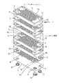
図1及び図2に示すように、本発明のプレート式熱交換器1は、上下のカバープレート2,3の間にヘリンボーンプレート4が複数枚積層されると共に、各ヘリンボーンプレート4の間にそれぞれ補強プレート18が積層されて成り、カバープレート2,3とヘリンボーンプレート4の間及び各ヘリンボーンプレート4の間に、熱交換される2流体の流路が形成されている。
なお、カバープレート2,3、ヘリンボーンプレート4及び補強プレート18は、チタン、ステンレス等のロウ付けで接合できる金属を素材とする。
Hereinafter, embodiments of the present invention will be described in detail with reference to the drawings.
As shown in FIGS. 1 and 2, the plate heat exchanger 1 according to the present invention includes a plurality of herringbone plates 4 stacked between upper and
The
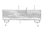
上下のカバープレート2,3は平板よりなり、図3に示すように、下のカバープレート3の四隅には、それぞれ2流体の出入り口となる第1乃至第4の透孔5,6,7,8が穿設されている。
そして、カバープレート3の第1の透孔5には、一方の流体を供給するための第1のニップル9が連結され、その対角線上に対向する第2の透孔6には、一方の流体を排出するための第2のニップル10が連結される。
また、他の対角線の一端部にある第3の透孔7には、他方の流体を供給するための第3のニップル11が連結され、これに対向する第4の透孔8には、他方の流体を排出するための第4のニップル12が連結される。
The upper and
A first nipple 9 for supplying one fluid is connected to the first through-hole 5 of the
A
図1に示すように、ヘリンボーンプレート4には、面積を増大させると共に、流路を流れる流体に乱流を発生させるために、凹凸状のヘリンボーン模様13が形成されている。また、ヘリンボーンプレート4の周縁に沿って、ヘリンボーンプレート4の間に形成される流路の厚みよりやや高い縁壁14が立設されている。
ヘリンボーンプレート4の四隅には、それぞれ2流体が上昇及び下降するための円形孔15が穿設されると共に、一方の対角線の両端部に形成された円形孔15の周縁には、それぞれスペーサとなる筒部16が立設されている。
As shown in FIG. 1, an
なお、最も上段のヘリンボーンプレート4には、図1に示すように、円形孔15が穿設されず、1本の対角線の両端部にそれぞれ3個の補強用突起17が形成されている。
これらのヘリンボーンプレート4は、上下に配置されたもののヘリンボーン模様13が逆向きになるように、且つ、円形孔15の周囲に形成された筒部16が一枚おきに上下に対向するように、補強プレート18を挟んで積層される。
As shown in FIG. 1, the uppermost herringbone plate 4 is not provided with
These herringbone plates 4 are arranged up and down so that the
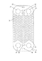
補強プレート18は、ヘリンボーンプレート4とほぼ同形の平板より成り、図4に示すように、補強プレート18の四隅部において、ヘリンボーンプレート4の円形孔15と対応する位置に、円形の切除部21が形成されている。
また、補強プレート18には、その上下に配置されたヘリンボーンプレート4のヘリンボーン模様13がない部分に、多数の透孔20が形成され、ヘリンボーンプレート4間に形成された流路における流体の流れを阻害しないようになっている。
透孔20の形状は、ヘリンボーン模様13の位置を避けるものであれば、円形、三角形、四角形、不規則形等のいかなる形状であっても良い。
The
The reinforcing
The shape of the through
上記のように、上下のカバープレート2,3と、複数のヘリンボーンプレート4及び補強プレート18が、ヘリンボーンプレート4間にそれぞれ補強プレート18を挟んで積層され、上下に配置されたカバープレート2,3とヘリンボーンプレート4の周縁がロウ付け接合される。
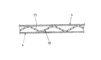
また、図5に示すように、ヘリンボーンプレート4のヘリンボーン模様13の頂部と、その上下に配置されたカバープレート2,3及び補強プレート18がロウ付け接合される。補強プレート18の透孔20は、ヘリンボーン模様13を避けた位置に形成されているので、ヘリンボーン模様13の頂部は補強プレート18に対して線接触し、ロウ付け接合部は帯状に延びる。
As described above, the upper and
Further, as shown in FIG. 5, the top of the
さらに、ヘリンボーンプレート4の筒部16の先端と、その上段のヘリンボーンプレート4の下面とがロウ付け接合される。
従って、カバープレート2,3及びヘリンボーンプレート4の間に形成される流路は、1層おきに連通している。
また、第1のニップル9及び第2のニップル10は下のカバープレート3にロウ付けされ、第3のニップル11及び第4のニップル12は、最も下段のヘリンボーンプレート4にロウ付けされる。
Further, the distal end of the
Therefore, the flow paths formed between the
The first nipple 9 and the
そして、第1のニップル9及び第2のニップル10が連結される第1の透孔5及び第2の透孔6の直上には、最も下段のヘリンボーンプレート4の筒部16を有する円形孔15が配置され、第3のニップル11及び第4のニップル12が連結される第3の透孔7及び第4の透孔8の直上には、最も下段のヘリンボーンプレート4の筒部16を有しない円形孔15が配置される。
従って、一方の流体は、第1のニップル9及び第1の透孔5を通して、プレート式熱交換器1の内部に流入し、筒部16で遮られて他方の流体の流路に進入することなく、その流体圧力によって一方の流体流路の最も上段に達し、1層おきに連通する流路を下って、第2のニップル10及び第2の透孔6からプレート式熱交換器1の外部に排出される。
A
Accordingly, one fluid flows into the plate heat exchanger 1 through the first nipple 9 and the first through-hole 5, is blocked by the
他方の流体は、第3のニップル11及び第3の透孔7を通して、プレート式熱交換器1の内部に流入し、同様にして、一方の流体の流路に進入することなく、他方の流体流路の最も上段に達し、1層おきに連通する流路を下って、第4のニップル12及び第4の透孔8からプレート式熱交換器1の外部に排出される。
そして、この間に、一方の流体と他方の流体との間で効率よく熱交換が行われる。また、ヘリンボーンプレート4と補強プレート18とは線接触して広い面積でロウ付けされているので、流体の圧力によってロウ付け接合部が破損する心配がない。
なお、プレート式熱交換器の細部の構造は、上記実施例に限定されない。例えば、ヘリンボーンプレート4及び補強プレート18の枚数、ヘリンボーン模様の形状等は、必要に応じて適宜選択することができる。
The other fluid flows into the plate heat exchanger 1 through the
During this time, heat exchange is efficiently performed between one fluid and the other fluid. In addition, since the herringbone plate 4 and the
The detailed structure of the plate heat exchanger is not limited to the above embodiment. For example, the number of the herringbone plates 4 and the reinforcing
1 プレート式熱交換器
2 上のカバープレート
3 下のカバープレート
4 ヘリンボーンプレート
5 第1の透孔
6 第2の透孔
7 第3の透孔
8 第4の透孔
9 第1のニップル
10 第2のニップル
11 第3のニップル
12 第4のニップル
13 ヘリンボーン模様
14 縁壁
15 円形孔
16 筒部
17 突起
18 補強プレート
20 透孔
21 切除部
DESCRIPTION OF SYMBOLS 1 Plate
Claims (1)
In a plate heat exchanger in which a plurality of herringbone plates having an uneven herringbone pattern are stacked and a flow path is formed between each herringbone plate, a reinforcing plate is stacked between each herringbone plate, and the herringbone pattern The plate-type heat exchanger is characterized in that a top portion of the reinforcing plate and the reinforcing plate are line-contacted and brazed and a large number of through holes are formed in a portion excluding the brazed joint portion of the reinforcing plate.
Priority Applications (1)
| Application Number | Priority Date | Filing Date | Title |
|---|---|---|---|
| JP2004098469A JP2005282961A (en) | 2004-03-30 | 2004-03-30 | Plate type heat exchanger |
Applications Claiming Priority (1)
| Application Number | Priority Date | Filing Date | Title |
|---|---|---|---|
| JP2004098469A JP2005282961A (en) | 2004-03-30 | 2004-03-30 | Plate type heat exchanger |
Publications (1)
| Publication Number | Publication Date |
|---|---|
| JP2005282961A true JP2005282961A (en) | 2005-10-13 |
Family
ID=35181556
Family Applications (1)
| Application Number | Title | Priority Date | Filing Date |
|---|---|---|---|
| JP2004098469A Pending JP2005282961A (en) | 2004-03-30 | 2004-03-30 | Plate type heat exchanger |
Country Status (1)
| Country | Link |
|---|---|
| JP (1) | JP2005282961A (en) |
Cited By (5)
| Publication number | Priority date | Publication date | Assignee | Title |
|---|---|---|---|---|
| JP2007183071A (en) * | 2006-01-10 | 2007-07-19 | Tokyo Bureizu Kk | High-pressure-resistant compact heat exchanger and manufacturing method of the same |
| WO2010090557A1 (en) * | 2009-02-04 | 2010-08-12 | Alfa Laval Corporate Ab | A plate heat exchanger |
| JP2010249432A (en) * | 2009-04-16 | 2010-11-04 | Mitsubishi Electric Corp | Plate type heat exchanger and refrigerating cycle device using the same |
| WO2022045607A1 (en) * | 2020-08-31 | 2022-03-03 | 주식회사 경동나비엔 | Heat exchanger assembly and water heater comprising same |
| US11486657B2 (en) | 2018-07-17 | 2022-11-01 | Tranter, Inc. | Heat exchanger heat transfer plate |
-
2004
- 2004-03-30 JP JP2004098469A patent/JP2005282961A/en active Pending
Cited By (5)
| Publication number | Priority date | Publication date | Assignee | Title |
|---|---|---|---|---|
| JP2007183071A (en) * | 2006-01-10 | 2007-07-19 | Tokyo Bureizu Kk | High-pressure-resistant compact heat exchanger and manufacturing method of the same |
| WO2010090557A1 (en) * | 2009-02-04 | 2010-08-12 | Alfa Laval Corporate Ab | A plate heat exchanger |
| JP2010249432A (en) * | 2009-04-16 | 2010-11-04 | Mitsubishi Electric Corp | Plate type heat exchanger and refrigerating cycle device using the same |
| US11486657B2 (en) | 2018-07-17 | 2022-11-01 | Tranter, Inc. | Heat exchanger heat transfer plate |
| WO2022045607A1 (en) * | 2020-08-31 | 2022-03-03 | 주식회사 경동나비엔 | Heat exchanger assembly and water heater comprising same |
Similar Documents
| Publication | Publication Date | Title |
|---|---|---|
| JP6163190B2 (en) | Heat exchanger | |
| DK1794529T3 (en) | Heat exchanger with recess pattern | |
| EP1998132B1 (en) | Rib plate type heat exchanger | |
| JP5838048B2 (en) | Oil cooler | |
| JP5872859B2 (en) | Heat exchanger | |
| JP2008116138A (en) | Heat exchange plate | |
| JP2005282961A (en) | Plate type heat exchanger | |
| JP2006183945A (en) | Oil cooler | |
| JP5105183B2 (en) | Heat exchange unit and heat exchanger using the same | |
| US20070151717A1 (en) | Heat exchange plate | |
| JP2016176618A (en) | Heat exchanger | |
| JP6938960B2 (en) | Micro flow path heat exchanger | |
| JP5341549B2 (en) | heatsink | |
| JP2010249399A (en) | Plate type heat exchanger | |
| JP2005291671A (en) | Stacked heat exchanger | |
| JP6153818B2 (en) | Oil cooler | |
| JP2014126258A (en) | Heat exchanger | |
| KR200275401Y1 (en) | Resisting pressure construction of board type heat exchange | |
| JP2007024343A (en) | Safety heat exchanging plate and safety heat exchanger using the same | |
| JP2005134073A (en) | Plate type heat exchanger | |
| JP6786868B2 (en) | Perforated plate for liquid filling nozzle, laminated plate for liquid filling nozzle and liquid filling device | |
| JP6079410B2 (en) | Plate heat exchanger | |
| KR20020025137A (en) | Resisting pressure construction of board type heat exchange | |
| JP2005207725A (en) | Heat exchanger | |
| JP3040213B2 (en) | Plate heat exchanger |
Legal Events
| Date | Code | Title | Description |
|---|---|---|---|
| A977 | Report on retrieval |
Effective date: 20061129 Free format text: JAPANESE INTERMEDIATE CODE: A971007 |
|
| A131 | Notification of reasons for refusal |
Free format text: JAPANESE INTERMEDIATE CODE: A131 Effective date: 20061212 |
|
| A02 | Decision of refusal |
Effective date: 20070508 Free format text: JAPANESE INTERMEDIATE CODE: A02 |