JP2005291671A - Stacked heat exchanger - Google Patents
Stacked heat exchanger Download PDFInfo
- Publication number
- JP2005291671A JP2005291671A JP2004111005A JP2004111005A JP2005291671A JP 2005291671 A JP2005291671 A JP 2005291671A JP 2004111005 A JP2004111005 A JP 2004111005A JP 2004111005 A JP2004111005 A JP 2004111005A JP 2005291671 A JP2005291671 A JP 2005291671A
- Authority
- JP
- Japan
- Prior art keywords
- heat transfer
- end plate
- tank
- transfer plates
- plate
- Prior art date
- Legal status (The legal status is an assumption and is not a legal conclusion. Google has not performed a legal analysis and makes no representation as to the accuracy of the status listed.)
- Pending
Links
- 239000012530 fluid Substances 0.000 claims abstract description 52
- 238000004891 communication Methods 0.000 claims abstract description 28
- 238000010030 laminating Methods 0.000 claims description 3
- 238000005219 brazing Methods 0.000 abstract description 5
- 230000003014 reinforcing effect Effects 0.000 abstract 2
- 238000007789 sealing Methods 0.000 abstract 1
- 238000000034 method Methods 0.000 description 6
- 230000002093 peripheral effect Effects 0.000 description 5
- 238000005452 bending Methods 0.000 description 3
- 239000007788 liquid Substances 0.000 description 2
- 239000002184 metal Substances 0.000 description 1
Images

Landscapes
- Heat-Exchange Devices With Radiators And Conduit Assemblies (AREA)
Abstract
Description
本発明は、複数枚の伝熱プレートを積層することで伝熱プレート間に流体通路を構成した積層型熱交換器に関するものである。 The present invention relates to a stacked heat exchanger in which a plurality of heat transfer plates are stacked to form a fluid passage between the heat transfer plates.
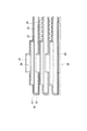
従来の積層型熱交換器としては、図5に示すように、タンク部構成用の連通孔35、36を有した複数の伝熱プレート31、32を順次積層することにより、隣接する伝熱プレート31、32間に流体通路27、28を形成すると共に、前記連通孔35、36を連ねることで、伝熱プレート31、32の積層体に、流体通路27に連通するタンク部34を形成したものが知られている。
As shown in FIG. 5, a conventional stacked heat exchanger includes a plurality of
この場合、伝熱プレート31、32は1対で扁平なチューブ30を構成しており、1対の伝熱プレート31、32よりなるチューブ30を多段に積層することで、伝熱プレート31、32の積層体が構成されている。
In this case, the
図示のタンク部34は、チューブ30内の第1流体通路27の一端に連通し、図示外のタンク部が第1流体通路27の他端に連通している。従って、一方のタンク部から第1熱交換流体を導入し他方のタンク部から導出することで、第1熱交換流体を第1流体通路27の内部に流すことができる。そして、第1流体通路27を第1熱交換流体が流れる間に、伝熱プレート31、32を介して隣接する第2流体通路28内を流れる第2熱交換流体との間で熱交換を行う。
The illustrated
なお、隣接するチューブ30とチューブ30との間に確保される第2流体通路28を、開放した通路として、空気を流通させる場合には、図示のように、第2流体通路28にアウタフィン33を設けるのが一般的である。また、第2流体通路28を、第1流体通路27と同様に閉じた流路空間として、液体等の熱交換流体を流通させる場合には、伝熱プレート31、32の積層体に更にもう1組の別系統のタンク部を設けて、流体(第2熱交換流体)を流通させるようにする。また、閉じた空間として構成する場合には、流体通路27、28に必要に応じて図示しないインナフィンを設けるのが一般的である。
When the
また、伝熱プレート31、32の積層体の積層方向の両側部には、伝熱プレート31を補強し且つ前記タンク部24に連通する出入口(通常、出入口パイプが取り付けられる)を有する第1エンドプレート(図示略)と、伝熱プレート32を補強し且つ前記タンク部24の端部を封止する第2エンドプレート38とがそれぞれ配設されている。伝熱プレート31、32は各層共通のものを用いることが多く、下側の第2エンドプレート38はタンク部24の端部を直接塞ぐことになるため、タンク部24の内圧が直接的に第2エンドプレート38にかかることになる。
A first end having an inlet / outlet (usually attached with an inlet / outlet pipe) that reinforces the
なお、このような熱交換器の類似技術は、特許文献1に開示されている。
上述したように複数枚の伝熱プレートを積層して構成した積層型熱交換器では、耐圧性能の向上のために積層方向の最外部にエンドプレートを配置しているのが一般的であるが、従来では、伝熱プレートとエンドプレートの位置決めがないために、ロウ付け時に位置ズレを起こしてしまうことがあった。その点、特許文献1に記載の技術では、伝熱プレートの周縁部にリブが設けられており、そのリブの働きにより、ある程度エンドプレートの位置決め機能が期待できるようになっているが、リブがある分だけ重くなってしまう可能性があった。 As described above, in a stacked heat exchanger configured by stacking a plurality of heat transfer plates, the end plate is generally arranged at the outermost part in the stacking direction in order to improve the pressure resistance performance. Conventionally, since there is no positioning between the heat transfer plate and the end plate, there has been a case where a positional deviation occurs during brazing. In that respect, in the technique described in Patent Document 1, ribs are provided on the peripheral edge of the heat transfer plate, and the function of the ribs can be expected to provide a certain end plate positioning function. There was a possibility of getting heavier by a certain amount.
本発明の目的は、大幅な重量増加を招くことなく、ロウ付け時の伝熱プレートとエンドプレートの位置合わせを確実に行うことができ、製品の品質向上が図れるようにした積層型熱交換器を提供することにある。 An object of the present invention is to provide a stacked heat exchanger capable of reliably aligning a heat transfer plate and an end plate during brazing without causing a significant increase in weight and improving product quality. Is to provide.
請求項1の発明は、タンク部構成用の連通孔を有した複数の伝熱プレートを積層することにより、隣接する伝熱プレート間に流体通路を形成すると共に、前記連通孔を連ねることで、伝熱プレートの積層体に、前記各流体通路に連通するタンク部を形成し、伝熱プレートの積層体の積層方向の両端部にそれぞれ、伝熱プレートを補強し且つタンク部に連通する出入口を有した第1エンドプレートと、伝熱プレートを補強し且つタンク部の端部を封止する第2エンドプレートとを配設した積層型熱交換器において、前記第2エンドプレートの内面に、該エンドプレートに隣接する伝熱プレートの前記連通孔に嵌まる凸部を設けたことを特徴とする。 The invention of claim 1 forms a fluid passage between adjacent heat transfer plates by laminating a plurality of heat transfer plates having communication holes for tank part configuration, and connects the communication holes. A tank portion communicating with each of the fluid passages is formed in the laminated body of the heat transfer plates, and an inlet / outlet that reinforces the heat transfer plate and communicates with the tank portion is provided at both ends of the laminated body of the heat transfer plate. In a stacked heat exchanger in which a first end plate having a second end plate that reinforces the heat transfer plate and seals the end of the tank portion is disposed on the inner surface of the second end plate, Protrusions that fit into the communication holes of the heat transfer plate adjacent to the end plate are provided.
請求項2の発明は、請求項1において、前記凸部を前記第2エンドプレートを局部的に凸に湾曲させることで形成したことを特徴とする。 According to a second aspect of the present invention, in the first aspect, the convex portion is formed by locally bending the second end plate so as to be convex.
請求項3の発明は、請求項1において、前記凸部を、前記第2エンドプレートの内面に当板を張り付けることで形成したことを特徴とする。 According to a third aspect of the present invention, in the first aspect, the convex portion is formed by attaching a contact plate to an inner surface of the second end plate.
請求項4の発明は、請求項1乃至3のいずれか一項において、前記タンク部が、前記伝熱プレートの積層体の4箇所に配置されており、4つのタンク部を頂点とする四角形の対角位置にあるタンク部の位置に対応させて前記凸部を設けたことを特徴とする。 A fourth aspect of the present invention is the method according to any one of the first to third aspects, wherein the tank portion is disposed at four locations of the laminated body of the heat transfer plates, and is a quadrangular shape having four tank portions as apexes. The convex portion is provided corresponding to the position of the tank portion at the diagonal position.
請求項5の発明は、請求項1乃至4のいずれか一項において、前記連通孔を円孔とし、前記凸部を連通孔の径に合致する円形状に形成したことを特徴とする。 According to a fifth aspect of the present invention, in any one of the first to fourth aspects, the communication hole is a circular hole, and the convex portion is formed in a circular shape that matches the diameter of the communication hole.
請求項1の発明によれば、伝熱プレートを補強し且つタンク部の端部を封止する第2エンドプレートの内面に、該エンドプレートに隣接する伝熱プレートのタンク部構成用の連通孔に嵌まる凸部を設けたので、その凸部を伝熱プレートの連通孔に嵌めることにより、伝熱プレートの積層体と第2エンドプレートとの位置決めを行うことができる。従って、位置ズレなくエンドプレートをロウ付けすることができ、製品の品質の向上を図ることができる。 According to the first aspect of the present invention, the inner surface of the second end plate that reinforces the heat transfer plate and seals the end of the tank portion has a communication hole for the tank portion configuration of the heat transfer plate adjacent to the end plate. Since the convex part which fits in is provided, the positioning of the laminated body of the heat transfer plate and the second end plate can be performed by fitting the convex part into the communication hole of the heat transfer plate. Therefore, it is possible to braze the end plate without positional deviation, and to improve the quality of the product.
しかも、タンク部の内方に突出した凸部が、タンク部の内圧を受けることになるから、耐圧性能的に弱部であったタンク部の位置におけるエンドプレートの耐圧性を高めることができる。その結果、エンドプレート全体の肉厚軽減が可能となり、軽量化を図ることができる。 And since the convex part which protruded inward of the tank part will receive the internal pressure of a tank part, the pressure resistance of the end plate in the position of the tank part which was weak in pressure resistance performance can be improved. As a result, the thickness of the entire end plate can be reduced, and the weight can be reduced.
すなわち、最外端の伝熱プレートは、特別なもの(連通孔が塞がったタイプのもの)を用いない限り、他の伝熱プレートと同様の連通孔を有しており、この部分を封止する第2エンドプレートにはタンク部の内圧が直にかかる。従って、エンドプレート上の他の部分は、伝熱プレートとの重なりによって内圧を受けることができるが、タンク部の位置では、エンドプレートのみでタンク部の内圧を受けなくてはならないから、この部分が耐圧上の弱部となる。このため、その弱部の耐圧性を十分にカバーできるように、エンドプレートの肉厚を決めざるを得ず、それにより、他の部分については、過剰な肉厚となる傾向があった。 In other words, the outermost heat transfer plate has the same communication holes as other heat transfer plates unless special ones (types with closed communication holes) are used. The internal pressure of the tank portion is directly applied to the second end plate. Therefore, other parts on the end plate can receive the internal pressure due to the overlap with the heat transfer plate, but at the position of the tank part, the internal pressure of the tank part must be received only by the end plate. Is a weak part on the pressure resistance. For this reason, the thickness of the end plate has to be determined so as to sufficiently cover the pressure resistance of the weak portion, and as a result, the other portions tend to be excessively thick.
この点、請求項1の発明では、前記凸部を設けることで、1枚のプレートとしての耐圧性の強化を図ることができるので、その分、エンドプレートの肉厚軽減に貢献することができる。また、エンドプレートの内面に凸部を設けるだけの簡単な構成であるから、特許文献1に記載の技術のように、伝熱プレートの周縁部のリブを利用するものと違って、重量増加を最小限に留めることができる。 In this respect, in the invention of claim 1, by providing the convex portion, it is possible to enhance the pressure resistance as a single plate, and accordingly, it can contribute to the reduction of the thickness of the end plate. . Moreover, since it is a simple structure which only provides a convex part in the inner surface of an end plate, unlike what uses the rib of the peripheral part of a heat exchanger plate like the technique of patent document 1, a weight increase is carried out. Can be kept to a minimum.
請求項2の発明によれば、第2エンドプレートを局部的に凸に湾曲させることにより前記凸部を形成したので、プレスのみで加工でき、加工が容易となる。
According to invention of
請求項3の発明によれば、前記第2エンドプレートの内面に当板を張り付けることにより前記凸部を形成したので、凸部の周縁の段差を明確に出すことができ、位置決めの確実化と耐圧強化を図ることができる。 According to the invention of claim 3, since the convex portion is formed by attaching the contact plate to the inner surface of the second end plate, the step of the peripheral edge of the convex portion can be made clear, and the positioning is ensured. Withstand pressure can be increased.
請求項4の発明によれば、4つのタンク部を頂点とする四角形の対角位置にあるタンク部の位置に対応させて前記凸部を設けたので、最低限の加工で確実な位置決めを行うことができる。 According to the fourth aspect of the present invention, since the convex portions are provided corresponding to the positions of the square diagonal positions with the four tank portions as apexes, reliable positioning is performed with a minimum of processing. be able to.
請求項5の発明によれば、タンク部構成用の連通孔を円孔とし、前記凸部を連通孔の径に合致する円形状に形成したので、位置決めの確実化を図ることができる。 According to the fifth aspect of the present invention, since the communication hole for configuring the tank portion is a circular hole and the convex portion is formed in a circular shape that matches the diameter of the communication hole, the positioning can be ensured.
以下、本発明を実施するための最良の形態となる実施例を図面に基づいて説明する。 DESCRIPTION OF THE PREFERRED EMBODIMENTS Embodiments that are the best mode for carrying out the present invention will be described below with reference to the drawings.
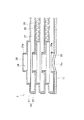
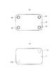
図1は実施例1に係わる積層型熱交換器(以下、熱交換器という)の部分断面図であり、図2のA−A断面を示す。図2は実施例1に係わる熱交換器の概略斜視図である。 FIG. 1 is a partial cross-sectional view of a stacked heat exchanger (hereinafter referred to as a heat exchanger) according to Example 1, and shows a cross section taken along the line AA of FIG. FIG. 2 is a schematic perspective view of the heat exchanger according to the first embodiment.
実施例1に係わる熱交換器1は、図2に示すように、熱交換流体の流れるコア部2と、コア部2の両端に配設された第1エンドプレート10及び第2エンドプレート11と、第1エンドプレート10に連結された出入口パイプ3、4、5、6とから構成されている。出入口パイプ3、4、5、6は、平面視矩形状のコア部2の四隅に配置されており、対角位置にあるもの同士が対をなし、対をなすもののうちの一方がコア部2に流体を導入する側、他方がコア部2から流体を導出する側となっている。これらの出入口パイプ3〜6は、コア部2に形成された4つのタンク部にそれぞれ連通している。
As shown in FIG. 2, the heat exchanger 1 according to the first embodiment includes a
コア部2は、図1に示すように、プレスにより成形され、タンク部構成用の円形の連通孔25、26を有した複数の金属製の伝熱プレート21、22を順次積層することにより構成されている。これにより、隣接する伝熱プレート21、22間に第1、第2流体通路27、28が形成されると共に、連通孔25、26の連なりによって、伝熱プレート21、22の積層体に、流体通路27、28に連通するタンク部24(他のタンク部は図示していない)が形成されている。
As shown in FIG. 1, the
この場合、伝熱プレート21、22は1対で扁平なチューブ20を構成しており、1対の伝熱プレート21、22よりなるチューブ20を多段に積層することで、コア部(伝熱プレートの積層体)2が構成されている。なお、各伝熱プレート21、22の連通孔25、26の周縁部には、同方向を向いた起立壁25a、26aがバーリング加工されており、これら起立壁25a、25bを互いに嵌合することで、伝熱プレート21、22同士の位置決めがなされている。
In this case, the
図1に示すタンク部24は、チューブ20内の第1流体通路27の一端に連通し、図示していないタンク部が第1流体通路27の他端に連通している。従って、一方のタンク部から第1熱交換流体を導入し、他方のタンク部から導出することで、第1熱交換流体を第1流体通路27の内部に流すことができるようになっている。そして、第1流体通路27内を第1熱交換流体が流れる間に、伝熱プレート31、32を介して隣接する第2流体通路28内を流れる第2熱交換流体との間で熱交換を行うようになっている。
The
ここでは、隣接するチューブ20とチューブ20との間に確保される第2流体通路28も、閉じた流路空間として構成されており、内部に液体等の第2熱交換流体を流通させることができるようになっている。従って、図2に示す一方の対の出入口パイプ3、5がタンク部を介して第1流体通路27に接続されている場合は、他方の対の出入口パイプ4、6がタンク部を介して第2流体通路28に接続されている。
Here, the
なお、各流体通路27、28には必要に応じてインナフィン(図示略)が設けられている。但し、図1に示す第2流体通路28内の符号33は、第2流体通路28を開放した空気通路として利用する場合のアウタフィンを示している。
Each
ところで、コア部2の両側部に配設されたエンドプレート10、11のうち、第1エンドプレート10は、伝熱プレート31を補強し且つタンク部24(合計4つある)に連通する出入口(出入口パイプ3〜6が取り付けられている)を有している。また、第2エンドプレート11は、伝熱プレート32を補強し且つタンク部24の端部を封止する役目を担っている。
By the way, of the
第2エンドプレート11の内面には、該エンドプレート11に隣接する伝熱プレート22の連通孔26に嵌まる凸部11aが、エンドプレート11を局部的に湾曲させることにより形成されている。連通孔26が円形孔として形成されているので、凸部11aも連通孔26の径に合致した円形状に形成されている。そして、この凸部11aが連通孔26に嵌まることで、エンドプレート11がコア部2に対して位置決めされており、その状態で、エンドプレート11とコア部2がロウ付けされている。これにより、ロウ付け時に位置ズレを生じることなくエンドプレート11とコア部2とを接合することができるため、ロウ付け作業の確実化と品質の向上を達成することができる。
On the inner surface of the
この凸部11aは、図3(a),(b)に示すように、4つのタンク部24を頂点とする四角形の対角位置にあるタンク部の位置に対応させて配置されている。本実施例では、対角位置の2箇所に凸部11aを配置しているが、4つのタンク部24のすべての位置に対応させて凸部11aを配置していもよい。
As shown in FIGS. 3A and 3B, the
なお、第2エンドプレート11が、タンク部24の端部を封止するのは、最下層の伝熱プレート32が連通孔26を持つためである。このため、第2エンドプレート11には、タンク部24の内圧が直接かかることになる。
The
しかし、タンク部24の内方に突出した凸部11aが、タンク部24の内圧を受けることになるため、耐圧性能的に弱部であったタンク部24の位置におけるエンドプレート11の耐圧性を高めることができる。その結果、エンドプレート11全体の肉厚軽減が可能となり、軽量化を図ることができる。
However, since the
このように、本実施例の熱交換器1では、第2エンドプレート11に凸部11aを設けているので、それを伝熱プレート22の連通孔26に嵌めることにより、エンドプレート11を確実に位置決めしながらコア部2とロウ付けすることができる。しかも、エンドプレート11に凸部11aを設けるだけで位置決めできるから、特別な重量増を招くことはない。
Thus, in the heat exchanger 1 of the present embodiment, since the
また、その凸部11aは、エンドプレート11を局部的に凸に湾曲させることで形成してあるので、プレスのみで加工でき、容易に加工することができる。また、凸部11aは、4つのタンク部24を頂点とする四角形の対角位置にあるタンク部24の位置に対応させて配置しているので、最低限の加工で確実な位置決めを行うことができる。
Moreover, since the
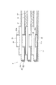
図4は、実施例2に係わる熱交換器の要部断面図である。図4は図1と同じく図2のA−A線における部分断面図に相当する。実施例1と同等部分には同一符号を付している。 FIG. 4 is a cross-sectional view of a main part of the heat exchanger according to the second embodiment. 4 corresponds to a partial cross-sectional view taken along the line AA of FIG. 2 as in FIG. The same parts as those in the first embodiment are denoted by the same reference numerals.
この実施例2の熱交換器においては、凸部11bを第2エンドプレート11を湾曲させて形成するのではなく、第2エンドプレート11の内面に当板29を張り付けることで形成している。当板29の厚さは、バーリング加工した起立壁26aと同程度に設定される。
In the heat exchanger according to the second embodiment, the
このように、第2エンドプレート11の内面に当板29を張り付けることにより凸部11bを形成した場合は、凸部11bの周縁の段差を明確に出すことができるので、エンドプレート11の位置決めの確実化と耐圧強化の確実化を図ることができる。
Thus, when the
1…熱交換器
2…コア部
3〜6…出入口パイプ
10…第1エンドプレート
11…第2エンドプレート
11a,11b…凸部
20…チューブ
21,22…伝熱プレート
24…タンク部
25,26…連通孔
25a,26a…起立壁
27…流体通路
27…第1流体通路
28…第2流体通路
29…当板
DESCRIPTION OF SYMBOLS 1 ...
Claims (5)
前記第2エンドプレート(11)の内面に、該エンドプレート(11)に隣接する伝熱プレート(22)の前記連通孔(26)に嵌まる凸部(11a、11b)を設けたことを特徴とする積層型熱交換器。 By laminating a plurality of heat transfer plates (21, 22) having communication holes (25, 26) for tank part configuration, fluid passages (27, 28) are provided between adjacent heat transfer plates (21, 22). And connecting the communication holes (25, 26) to the laminated body (2) of the heat transfer plates (21, 22), the tank portion (24) communicating with the fluid passages (27, 28). ) And the inlet / outlet (3, 4,...) That reinforces the heat transfer plate (21) and communicates with the tank portion (24) at both ends in the stacking direction of the stacked body (2) of the heat transfer plates. 5 and 6) and a second end plate (11) that reinforces the heat transfer plate (22) and seals the end of the tank portion (24). In the installed laminated heat exchanger,
Protrusions (11a, 11b) that fit into the communication holes (26) of the heat transfer plate (22) adjacent to the end plate (11) are provided on the inner surface of the second end plate (11). A laminated heat exchanger.
The said communicating hole (26) was used as the circular hole, and the said convex part (11a, 11b) was formed in the circular shape corresponding to the diameter of the communicating hole (26), The one of Claims 1 thru | or 4 characterized by the above-mentioned. A stacked heat exchanger according to 1.
Priority Applications (1)
| Application Number | Priority Date | Filing Date | Title |
|---|---|---|---|
| JP2004111005A JP2005291671A (en) | 2004-04-05 | 2004-04-05 | Stacked heat exchanger |
Applications Claiming Priority (1)
| Application Number | Priority Date | Filing Date | Title |
|---|---|---|---|
| JP2004111005A JP2005291671A (en) | 2004-04-05 | 2004-04-05 | Stacked heat exchanger |
Publications (1)
| Publication Number | Publication Date |
|---|---|
| JP2005291671A true JP2005291671A (en) | 2005-10-20 |
Family
ID=35324789
Family Applications (1)
| Application Number | Title | Priority Date | Filing Date |
|---|---|---|---|
| JP2004111005A Pending JP2005291671A (en) | 2004-04-05 | 2004-04-05 | Stacked heat exchanger |
Country Status (1)
| Country | Link |
|---|---|
| JP (1) | JP2005291671A (en) |
Cited By (7)
| Publication number | Priority date | Publication date | Assignee | Title |
|---|---|---|---|---|
| JP2007263472A (en) * | 2006-03-28 | 2007-10-11 | Univ Of Tokyo | Micro heat exchanger and manufacturing method thereof |
| JP2008144977A (en) * | 2006-12-06 | 2008-06-26 | Mahle Filter Systems Japan Corp | Oil cooler |
| JP2009521659A (en) * | 2005-12-22 | 2009-06-04 | アルファ ラヴァル コーポレイト アクチボラゲット | Means for plate heat exchangers |
| JP2010203691A (en) * | 2009-03-04 | 2010-09-16 | Panasonic Corp | Heat storage device and water heater using the same |
| JP2012107783A (en) * | 2010-11-15 | 2012-06-07 | Toyota Motor Corp | Vehicle heat exchanger |
| KR101813048B1 (en) * | 2014-10-30 | 2017-12-29 | 린나이코리아 주식회사 | Plate type heat exchanger |
| WO2019117312A1 (en) * | 2017-12-11 | 2019-06-20 | 株式会社ティラド | Stacked heat exchanger |
Citations (3)
| Publication number | Priority date | Publication date | Assignee | Title |
|---|---|---|---|---|
| JPH0410274U (en) * | 1990-05-18 | 1992-01-29 | ||
| JPH0476914U (en) * | 1990-11-15 | 1992-07-06 | ||
| JP2001099588A (en) * | 1999-09-29 | 2001-04-13 | Hisaka Works Ltd | Plate heat exchanger |
-
2004
- 2004-04-05 JP JP2004111005A patent/JP2005291671A/en active Pending
Patent Citations (3)
| Publication number | Priority date | Publication date | Assignee | Title |
|---|---|---|---|---|
| JPH0410274U (en) * | 1990-05-18 | 1992-01-29 | ||
| JPH0476914U (en) * | 1990-11-15 | 1992-07-06 | ||
| JP2001099588A (en) * | 1999-09-29 | 2001-04-13 | Hisaka Works Ltd | Plate heat exchanger |
Cited By (10)
| Publication number | Priority date | Publication date | Assignee | Title |
|---|---|---|---|---|
| JP2009521659A (en) * | 2005-12-22 | 2009-06-04 | アルファ ラヴァル コーポレイト アクチボラゲット | Means for plate heat exchangers |
| JP2007263472A (en) * | 2006-03-28 | 2007-10-11 | Univ Of Tokyo | Micro heat exchanger and manufacturing method thereof |
| JP2008144977A (en) * | 2006-12-06 | 2008-06-26 | Mahle Filter Systems Japan Corp | Oil cooler |
| JP2010203691A (en) * | 2009-03-04 | 2010-09-16 | Panasonic Corp | Heat storage device and water heater using the same |
| JP2012107783A (en) * | 2010-11-15 | 2012-06-07 | Toyota Motor Corp | Vehicle heat exchanger |
| DE112011103775B4 (en) * | 2010-11-15 | 2019-03-21 | T.Rad Co., Ltd. | Automotive heat exchanger |
| KR101813048B1 (en) * | 2014-10-30 | 2017-12-29 | 린나이코리아 주식회사 | Plate type heat exchanger |
| WO2019117312A1 (en) * | 2017-12-11 | 2019-06-20 | 株式会社ティラド | Stacked heat exchanger |
| JPWO2019117312A1 (en) * | 2017-12-11 | 2020-12-03 | 株式会社ティラド | Laminated heat exchanger |
| JP7244438B2 (en) | 2017-12-11 | 2023-03-22 | 株式会社ティラド | Laminated heat exchanger |
Similar Documents
| Publication | Publication Date | Title |
|---|---|---|
| CN100510600C (en) | Inverted lid sealing plate for heat exchanger | |
| US6920916B2 (en) | Layered heat exchangers | |
| JP2007248047A (en) | Layered heat exchanger | |
| EP0932011A2 (en) | Oil cooler structure | |
| US7520319B2 (en) | Stacking-type, multi-flow, heat exchanger | |
| EP4006477A1 (en) | Plate heat exchanger | |
| JP2005291671A (en) | Stacked heat exchanger | |
| WO2015093625A1 (en) | Header plateless heat exchanger | |
| JP2005147427A (en) | Stacked heat exchanger | |
| WO2013138931A1 (en) | Fitting assembly sandwiched between two annular plate walls | |
| JP7456795B2 (en) | Stacked Heat Exchanger | |
| JP2006342997A (en) | Heat exchanger | |
| JP2008249241A (en) | Heat exchanger | |
| JPH07190650A (en) | Heat exchanger | |
| CN112414181B (en) | Plate Heat Exchanger | |
| CN212721042U (en) | Plate Heat Exchanger | |
| JP2005121297A (en) | Heat exchanger | |
| KR20220102578A (en) | Plate-type heat exchanger having bracket reinforce structure | |
| JP4312640B2 (en) | Stacked heat exchanger | |
| JP2004293880A (en) | Stacked heat exchanger | |
| JP2007147173A (en) | Heat exchanger and its manufacturing method | |
| JP2002062084A (en) | Heat exchanger | |
| JP2005274067A (en) | Stacked heat exchanger | |
| JP4471423B2 (en) | Plate heat exchanger | |
| JP2005315521A (en) | Heat exchange apparatus |
Legal Events
| Date | Code | Title | Description |
|---|---|---|---|
| A621 | Written request for application examination |
Free format text: JAPANESE INTERMEDIATE CODE: A621 Effective date: 20070329 |
|
| A977 | Report on retrieval |
Free format text: JAPANESE INTERMEDIATE CODE: A971007 Effective date: 20091210 |
|
| A131 | Notification of reasons for refusal |
Free format text: JAPANESE INTERMEDIATE CODE: A131 Effective date: 20091215 |
|
| A02 | Decision of refusal |
Free format text: JAPANESE INTERMEDIATE CODE: A02 Effective date: 20100413 |