JP2005178593A - Opening and closing device of lid - Google Patents
Opening and closing device of lid Download PDFInfo
- Publication number
- JP2005178593A JP2005178593A JP2003422653A JP2003422653A JP2005178593A JP 2005178593 A JP2005178593 A JP 2005178593A JP 2003422653 A JP2003422653 A JP 2003422653A JP 2003422653 A JP2003422653 A JP 2003422653A JP 2005178593 A JP2005178593 A JP 2005178593A
- Authority
- JP
- Japan
- Prior art keywords
- lid
- link arm
- closing device
- opening
- spring
- Prior art date
- Legal status (The legal status is an assumption and is not a legal conclusion. Google has not performed a legal analysis and makes no representation as to the accuracy of the status listed.)
- Granted
Links
- 230000000694 effects Effects 0.000 description 16
- 238000013016 damping Methods 0.000 description 6
- 238000005452 bending Methods 0.000 description 1
- 238000007796 conventional method Methods 0.000 description 1
- 230000000149 penetrating effect Effects 0.000 description 1
Images


Classifications
-
- B—PERFORMING OPERATIONS; TRANSPORTING
- B60—VEHICLES IN GENERAL
- B60R—VEHICLES, VEHICLE FITTINGS, OR VEHICLE PARTS, NOT OTHERWISE PROVIDED FOR
- B60R7/00—Stowing or holding appliances inside vehicle primarily intended for personal property smaller than suit-cases, e.g. travelling articles, or maps
- B60R7/04—Stowing or holding appliances inside vehicle primarily intended for personal property smaller than suit-cases, e.g. travelling articles, or maps in driver or passenger space, e.g. using racks
- B60R7/06—Stowing or holding appliances inside vehicle primarily intended for personal property smaller than suit-cases, e.g. travelling articles, or maps in driver or passenger space, e.g. using racks mounted on or below dashboards
-
- B—PERFORMING OPERATIONS; TRANSPORTING
- B65—CONVEYING; PACKING; STORING; HANDLING THIN OR FILAMENTARY MATERIAL
- B65D—CONTAINERS FOR STORAGE OR TRANSPORT OF ARTICLES OR MATERIALS, e.g. BAGS, BARRELS, BOTTLES, BOXES, CANS, CARTONS, CRATES, DRUMS, JARS, TANKS, HOPPERS, FORWARDING CONTAINERS; ACCESSORIES, CLOSURES, OR FITTINGS THEREFOR; PACKAGING ELEMENTS; PACKAGES
- B65D43/00—Lids or covers for rigid or semi-rigid containers
- B65D43/26—Mechanisms for opening or closing, e.g. pedal-operated
-
- E—FIXED CONSTRUCTIONS
- E05—LOCKS; KEYS; WINDOW OR DOOR FITTINGS; SAFES
- E05B—LOCKS; ACCESSORIES THEREFOR; HANDCUFFS
- E05B83/00—Vehicle locks specially adapted for particular types of wing or vehicle
- E05B83/28—Locks for glove compartments, console boxes, fuel inlet covers or the like
- E05B83/30—Locks for glove compartments, console boxes, fuel inlet covers or the like for glove compartments
-
- B—PERFORMING OPERATIONS; TRANSPORTING
- B60—VEHICLES IN GENERAL
- B60R—VEHICLES, VEHICLE FITTINGS, OR VEHICLE PARTS, NOT OTHERWISE PROVIDED FOR
- B60R11/00—Arrangements for holding or mounting articles, not otherwise provided for
- B60R2011/0001—Arrangements for holding or mounting articles, not otherwise provided for characterised by position
- B60R2011/0003—Arrangements for holding or mounting articles, not otherwise provided for characterised by position inside the vehicle
-
- B—PERFORMING OPERATIONS; TRANSPORTING
- B60—VEHICLES IN GENERAL
- B60R—VEHICLES, VEHICLE FITTINGS, OR VEHICLE PARTS, NOT OTHERWISE PROVIDED FOR
- B60R11/00—Arrangements for holding or mounting articles, not otherwise provided for
- B60R2011/0094—Arrangements for holding or mounting articles, not otherwise provided for characterised by means for covering after user, e.g. boxes, shutters or the like
Abstract
Description
この発明は、小物入れ等のリッドの開閉装置に関し、特に1本のスプリングのばね力を利用して、リッドを開方向と閉方向との両方向に開閉することができるようにしたものである。 The present invention relates to a lid opening / closing device such as an accessory case. In particular, the lid can be opened and closed in both an opening direction and a closing direction by utilizing the spring force of one spring.
従来、この種のリッドの開閉装置としては、リッドをスプリングにより、閉位置から開位置に付勢するものが知られている(特許文献1参照)。
しかし、上記した従来のリッドの開閉装置では、リッドを閉じる際に、手でリッドを閉じなければならず、面倒であるばかりでなく、スプリングのばね力に抗してリッドを閉じなければならないという問題点があった。
そこで、各請求項にそれぞれ記載された各発明は、上記した従来の技術の有する問題点に鑑みてなされたものであり、その目的とするところは、次の点にある。
(請求項1)
すなわち、請求項1に記載の発明は、1本のスプリングのばね力を利用して、リッドを開方向と閉方向との両方向に開閉することができるようにしたものである。
However, in the conventional lid opening and closing device described above, when the lid is closed, the lid must be closed by hand, which is troublesome and also requires that the lid be closed against the spring force of the spring. There was a problem.
Accordingly, each invention described in each claim has been made in view of the problems of the conventional techniques described above, and the object thereof is as follows.
(Claim 1)
That is, the invention according to
このため、請求項1に記載の発明によれば、スプリングが1本で済むので、部品点数が少なくて済むという利点がある。
また、請求項1に記載の発明によれば、リッドを閉方向にスプリングにより付勢しているので、リッドを確実に閉じることができる。
さらに、請求項1に記載の発明によれば、リッドを閉方向にスプリングにより付勢しているので、リッドが閉位置から不用意に開くのを防止することができる。
Therefore, according to the first aspect of the present invention, since only one spring is required, there is an advantage that the number of parts can be reduced.
According to the first aspect of the present invention, the lid is biased by the spring in the closing direction, so that the lid can be reliably closed.
Further, according to the first aspect of the present invention, since the lid is biased by the spring in the closing direction, the lid can be prevented from being inadvertently opened from the closed position.
このため、請求項1に記載の発明によれば、リッドを閉位置にロックするためのロック機構を省略することもできる。
(請求項2)
請求項2に記載の発明は、上記した請求項1に記載の発明の目的に加え、次の点を目的とする。
For this reason, according to the first aspect of the present invention, a lock mechanism for locking the lid in the closed position can be omitted.
(Claim 2)
The second aspect of the invention has the following object in addition to the object of the first aspect of the invention.
すなわち、請求項2に記載の発明は、比較的簡単な構造で、リッドを開方向と閉方向の両方向に開閉することができるようにしたものである。
(請求項3)
請求項3に記載の発明は、上記した請求項1又は請求項2に記載の発明の目的に加え、次の点を目的とする。
That is, the invention described in claim 2 is configured such that the lid can be opened and closed in both the opening direction and the closing direction with a relatively simple structure.
(Claim 3)
The invention described in claim 3 has the following object in addition to the object of the invention described in
すなわち、請求項3に記載の発明は、リッドを閉位置から45度、閉じることで、リッドをスプリングのばね力を利用して閉じることができるようにしたものである。
(請求項4)
請求項4に記載の発明は、上記した請求項1〜3のいずれか1項に記載の発明の目的に加え、次の点を目的とする。
That is, the invention according to claim 3 is configured such that the lid can be closed using the spring force of the spring by closing the lid 45 degrees from the closed position.
(Claim 4)
The invention according to claim 4 has the following object in addition to the object of the invention according to any one of
すなわち、請求項4に記載の発明は、ガイド溝とピンとの係合という比較的簡単な構造で、リッドを開方向と閉方向の両方向に開閉することができるようにしたものである。
(請求項5)
請求項5に記載の発明は、上記した請求項1〜4のいずれか1項に記載の発明の目的に加え、次の点を目的とする。
That is, the invention according to claim 4 is configured such that the lid can be opened and closed in both the opening direction and the closing direction with a relatively simple structure of engagement between the guide groove and the pin.
(Claim 5)
The invention described in claim 5 has the following object in addition to the object of the invention described in any one of
すなわち、請求項5に記載の発明は、ガイド溝にピンのロック部を設けることで、リッドを確実に開放することができるようにしたものである。
(請求項6)
請求項6に記載の発明は、上記した請求項1〜5のいずれか1項に記載の発明の目的に加え、次の点を目的とする。
That is, in the invention described in claim 5, the lid can be surely opened by providing the lock portion of the pin in the guide groove.
(Claim 6)
The invention described in claim 6 has the following object in addition to the object of the invention described in any one of
すなわち、請求項6に記載の発明は、リッドが開放する途中で、ピンをストッパーに係合させることで、ガイド溝中でピンを適正な位置に移動することができるようにしたものである。
(請求項7)
請求項7に記載の発明は、上記した請求項1〜6のいずれか1項に記載の発明の目的に加え、次の点を目的とする。
That is, according to the sixth aspect of the present invention, the pin can be moved to an appropriate position in the guide groove by engaging the pin with the stopper while the lid is being opened.
(Claim 7)
The invention described in claim 7 has the following object in addition to the object of the invention described in any one of
すなわち、請求項7に記載の発明は、プッシュアームを確実に復帰させることができるようにしたものである。
(請求項8)
請求項8に記載の発明は、上記した請求項1〜7のいずれか1項に記載の発明の目的に加え、次の点を目的とする。
That is, the invention described in claim 7 is configured to reliably return the push arm.
(Claim 8)
The invention according to claim 8 has the following object in addition to the object of the invention according to any one of
すなわち、請求項8に記載の発明は、ダンパー装置に減衰力により、ゆっくりと且つ静粛にリッドを開放させることができるようにしたものである。
これに加えて、請求項8に記載の発明は、ダンパー装置に減衰力により、ゆっくりと且つ静粛にリッドが閉じるようにすることができるようにしたものである。
That is, the invention according to claim 8 is configured such that the lid can be opened slowly and silently by the damping force of the damper device.
In addition, the invention according to claim 8 is configured such that the lid can be closed slowly and quietly by the damping force of the damper device.
各請求項にそれぞれ記載された各発明は、上記した各目的を達成するためになされたものであり、各発明の特徴点を図面に示した発明の実施の形態を用いて、以下に説明する。
なお、カッコ内の符号は、発明の実施の形態において用いた符号を示し、本発明の技術的範囲を限定するものではない。
また、図面番号も、発明の実施の形態において用いた図番を示し、本発明の技術的範囲を限定するものではない。
(請求項1)
請求項1に記載の発明は、次の点を特徴とする。
Each invention described in each claim has been made to achieve each of the above-mentioned objects, and features of each invention will be described below using embodiments of the invention shown in the drawings. .
In addition, the code | symbol in parenthesis shows the code | symbol used in embodiment of invention, and does not limit the technical scope of this invention.
Also, the drawing numbers indicate the drawing numbers used in the embodiments of the invention and do not limit the technical scope of the present invention.
(Claim 1)
The invention described in
すなわち、リッドの開閉装置は、例えば図1に示すように、次の構成を備える。
(1)ベース(30)
ベース(30)は、例えば図1に示すように、開口部(31)を有するものである。
(2)リッド(20)
リッド(20)は、例えば図1に示すように、ベース(30)に回転軸(35)を中心に回転可能に支持され、開口部(31)を開閉するものである。
That is, the lid opening / closing device has the following configuration, for example, as shown in FIG.
(1) Base (30)
For example, as shown in FIG. 1, the base (30) has an opening (31).
(2) Lid (20)
As shown in FIG. 1, for example, the lid (20) is supported by the base (30) so as to be rotatable about the rotation shaft (35), and opens and closes the opening (31).
(3)スプリング(70)
スプリング(70)は、例えば図1に示すように、1本である。
また、スプリング(70)は、例えば図2に示すように、ベース(30)とリッド(20)との間に掛け設けられている。
さらに、スプリング(70)は、リッド(20)が閉じた閉位置(例えば図2参照)を行き過ぎた押込位置(例えば図6参照)まで押し込まれることで引っ張られ、そのばね復元力により、リッド(20)を開放する方向に付勢するためのものである。
(3) Spring (70)
For example, as shown in FIG. 1, there is one spring (70).
The spring (70) is provided between the base (30) and the lid (20) as shown in FIG. 2, for example.
Further, the spring (70) is pulled by being pushed to the pushing position (for example, see FIG. 6) that has passed the closed position (for example, see FIG. 2) where the lid (20) is closed. 20) for urging in the opening direction.
また、スプリング(70)は、ばね復元力により開放されたリッド(20)が所定の角度(例えば図9参照)閉じられることで再度、引っ張られ、そのばね復元力により、リッド(20)を閉じる方向に付勢するためのものである。
(請求項2)
請求項2に記載の発明は、上記した請求項1に記載の発明の特徴点に加え、次の点を特徴とする。
The spring (70) is pulled again when the lid (20) opened by the spring restoring force is closed at a predetermined angle (see, for example, FIG. 9), and the lid (20) is closed by the spring restoring force. It is for urging in the direction.
(Claim 2)
The invention described in claim 2 is characterized by the following points in addition to the characteristics of the invention described in
すなわち、ベース(30)とリッド(20)との間には、例えば図1に示すように、次の構成を備える。
(1)第1リンクアーム(80)
第1リンクアーム(80)は、例えば図1に示すように、支持軸(37)により一端部がベース(30)に回転可能に支持されるものである。
That is, the following configuration is provided between the base (30) and the lid (20), for example, as shown in FIG.
(1) First link arm (80)
For example, as shown in FIG. 1, the first link arm (80) is rotatably supported at one end by a support shaft (37) on the base (30).
(2)第2リンクアーム(90)
第2リンクアーム(90)は、例えば図1に示すように、一端部が第1リンクアーム(80)にスライド可能に支持されている。
また、第2リンクアーム(90)は、例えば図1に示すように、他端部にピン(91)を有する。
(2) Second link arm (90)
For example, as shown in FIG. 1, the second link arm (90) is slidably supported by the first link arm (80) at one end.
Moreover, the 2nd link arm (90) has a pin (91) in the other end part, for example, as shown in FIG.
さらに、第2リンクアーム(90)は、例えば図2に示すように、第1リンクアーム(80)との間に掛け設けられたスプリング(70)のばね復元力により、第1リンクアーム(80)に接近する方向に付勢されるものである。
(3)プッシュアーム(100)
プッシュアーム(100)は、例えば図1に示すように、ベース(30)に支持され、リッド(20)が押込位置(例えば図6参照)まで押し込まれることで、第2リンクアーム(90)を第1リンクアーム(80)から離れる方向に移動させ、これによりスプリング(70)を引っ張るためのものである。
Further, as shown in FIG. 2, for example, the second link arm (90) is formed by the spring restoring force of the spring (70) provided between the first link arm (80) and the first link arm (80). ).
(3) Push arm (100)
For example, as shown in FIG. 1, the push arm (100) is supported by the base (30), and the lid (20) is pushed to the pushing position (see, for example, FIG. 6), so that the second link arm (90) is moved. The first link arm (80) is moved away from the first link arm (80), thereby pulling the spring (70).
(4)ガイド溝(24)
ガイド溝(24)は、例えば図1に示すように、リッド(20)に設けられ、ピン(91)を移動可能にガイドするとともに、リッド(20)が開放位置(例えば図8参照)から所定の角度(例えば図9参照)閉じられることで、ピン(91)を第1リンクアーム(80)から離れる方向に移動させ、これによりスプリング(70)を引っ張るためのものである。
(請求項3)
請求項3に記載の発明は、上記した請求項1又は請求項2に記載の発明の特徴点に加え、次の点を特徴とする。
(4) Guide groove (24)
For example, as shown in FIG. 1, the guide groove (24) is provided in the lid (20), guides the pin (91) so as to be movable, and the lid (20) is predetermined from an open position (for example, see FIG. 8). The pin (91) is moved in a direction away from the first link arm (80) by being closed at an angle (see, for example, FIG. 9), thereby pulling the spring (70).
(Claim 3)
The invention described in claim 3 is characterized by the following points in addition to the characteristics of the invention described in
すなわち、所定の角度は、45度(例えば図9参照)に設定されている。
(請求項4)
請求項4に記載の発明は、上記した請求項1〜3のいずれか1項に記載の発明の特徴点に加え、次の点を特徴とする。
第一に、ガイド溝(24)は、リッド(20)の回転軸(35)と、第1リンクアーム(80)の支持軸(37)とを結ぶ線の延長線(図示せず)を境にピン(91)の移動を許容するものである。
That is, the predetermined angle is set to 45 degrees (see, for example, FIG. 9).
(Claim 4)
The invention described in claim 4 is characterized by the following points in addition to the features of the invention described in any one of claims 1-3.
First, the guide groove (24) borders an extension line (not shown) of a line connecting the rotation shaft (35) of the lid (20) and the support shaft (37) of the first link arm (80). The pin (91) is allowed to move.
第二に、ピン(91)は、延長線(図示せず)を境に、リッド(20)の自由端部から離れる奥側に移動することで、リッド(20)を開放するようにしている(例えば図6〜7参照)。
ピン(91)は、延長線(図示せず)を境に、リッド(20)の自由端部に接近する手前側に移動することで、リッド(20)を閉じるようにしている(例えば図2及び図9参照)。
(請求項5)
請求項5に記載の発明は、上記した請求項1〜4のいずれか1項に記載の発明の特徴点に加え、次の点を特徴とする。
Second, the pin (91) moves to the back side away from the free end of the lid (20) with an extension line (not shown) as a boundary, thereby opening the lid (20). (See, for example, FIGS. 6-7).
The pin (91) moves to the front side approaching the free end of the lid (20) with an extension line (not shown) as a boundary, thereby closing the lid (20) (for example, FIG. 2). And FIG. 9).
(Claim 5)
The invention described in claim 5 is characterized by the following points in addition to the characteristics of the invention described in any one of
第一に、ガイド溝(24)は、リッド(20)が閉じた位置(例えば図2参照)で、第1リンクアーム(80)の支持軸(37)から離れる方向に延び、例えば図5に示すように、支持軸(37)に近い始端部(25)と、支持軸(37)から遠く離れるとともに、折れ曲がったロック部(26)とを備える。
第二に、プッシュアーム(100)は、例えば図6に示すように、第2リンクアーム(90)を第1リンクアーム(80)から離れる方向に移動させることで、ピン(91)を始端部(25)からロック部(26)に向かって移動するようにしている。
(請求項6)
請求項6に記載の発明は、上記した請求項1〜5のいずれか1項に記載の発明の特徴点に加え、次の点を特徴とする。
First, the guide groove (24) extends in a direction away from the support shaft (37) of the first link arm (80) when the lid (20) is closed (see, for example, FIG. 2). As shown, a start end portion (25) close to the support shaft (37) and a lock portion (26) which is far from the support shaft (37) and is bent.
Second, the push arm (100) moves the second link arm (90) away from the first link arm (80), for example, as shown in FIG. It moves from (25) toward the lock part (26).
(Claim 6)
The invention described in claim 6 is characterized by the following points in addition to the features of the invention described in any one of claims 1-5.
すなわち、ベース(30)には、例えば図7に示すように、リッド(20)が開放する途中でピン(91)に係合し、ピン(91)をロック部(26)から始端部(25)に向かって移動するためのストッパー(38)を設けている。
(請求項7)
請求項7に記載の発明は、上記した請求項1〜6のいずれか1項に記載の発明の特徴点に加え、次の点を特徴とする。
That is, for example, as shown in FIG. 7, the base (30) is engaged with the pin (91) while the lid (20) is being opened, and the pin (91) is moved from the lock portion (26) to the start end portion (25 ) Is provided with a stopper (38) for moving toward the head.
(Claim 7)
The invention described in claim 7 is characterized by the following points in addition to the characteristics of the invention described in any one of
第一に、プッシュアーム(100)は、例えば図1に示すように、次の構成を備える。
(1)軸止部(101)
軸止部(101)は、例えば図1に示すように、その長さの途中に位置し、ベース(30)に回転可能に支持されるものである。
(2)押圧部(例えばプッシュロッド120の押圧部123)
押圧部(例えばプッシュロッド120の押圧部123)は、例えば図1及び図2に示すように、軸止部(101)を挟んだ一端部に位置し、リッド(20)に向かって突出し、リッド(20)の自由端部により押し下げられるものである。
First, the push arm (100) has the following configuration, for example, as shown in FIG.
(1) Shaft stop (101)
For example, as shown in FIG. 1, the shaft stop portion (101) is positioned in the middle of its length and is rotatably supported by the base (30).
(2) Pressing part (for example, the pressing part 123 of the push rod 120)
The pressing portion (for example, the pressing portion 123 of the push rod 120) is located at one end of the shaft stopper portion (101) as shown in FIGS. 1 and 2, for example, and protrudes toward the lid (20). It is pushed down by the free end of (20).
(3)押上部(102)
押上部(102)は、例えば図1及び図6に示すように、軸止部(101)を挟んだ他端部に位置し、第1リンクアーム(80)から離れる方向に第2リンクアーム(90)を押し上げるためのものである。
第二に、プッシュアーム(100)とベース(30)との間には、例えば図6に示すように、リッド(20)の自由端部により押圧部(例えばプッシュロッド120の押圧部123)が押し下げられることで、軸止部(101)を中心に回転したプッシュアーム(100)を復帰させるための復帰ばね(110)を設けている。
(請求項8)
請求項8に記載の発明は、上記した請求項1〜7のいずれか1項に記載の発明の特徴点に加え、次の点を特徴とする。
(3) Pusher (102)
For example, as shown in FIGS. 1 and 6, the push-up portion (102) is located at the other end portion sandwiching the shaft stopper portion (101), and the second link arm (in the direction away from the first link arm (80)). 90) to push up.
Second, between the push arm (100) and the base (30), for example, as shown in FIG. 6, a pressing portion (for example, a pressing portion 123 of the push rod 120) is formed by the free end of the lid (20). A return spring (110) for returning the push arm (100) rotated about the shaft stop (101) by being pushed down is provided.
(Claim 8)
The invention described in claim 8 is characterized by the following points in addition to the characteristics of the invention described in any one of claims 1-7.
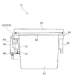
すなわち、ベース(30)とリッド(20)との間には、例えば図2に示すように、リッド(20)に作用する回転力を減衰するためのダンパー装置(50)を設けている。 That is, between the base (30) and the lid (20), for example, as shown in FIG. 2, a damper device (50) is provided for attenuating the rotational force acting on the lid (20).
本発明は、以上のように構成されているので、以下に記載されるような効果を奏する。
(請求項1)
請求項1に記載の発明によれば、次のような効果を奏する。
すなわち、請求項1に記載の発明によれば、1本のスプリングのばね力を利用して、リッドを開方向と閉方向との両方向に開閉することができる。
Since this invention is comprised as mentioned above, there exists an effect as described below.
(Claim 1)
According to invention of
That is, according to the first aspect of the present invention, the lid can be opened and closed in both the opening direction and the closing direction using the spring force of one spring.
このため、請求項1に記載の発明によれば、スプリングが1本で済むので、部品点数が少なくて済むという利点がある。
また、請求項1に記載の発明によれば、リッドを閉方向にスプリングにより付勢しているので、リッドを確実に閉じることができる。
さらに、請求項1に記載の発明によれば、リッドを閉方向にスプリングにより付勢しているので、リッドが閉位置から不用意に開くのを防止することができる。
Therefore, according to the first aspect of the present invention, since only one spring is required, there is an advantage that the number of parts can be reduced.
According to the first aspect of the present invention, the lid is biased by the spring in the closing direction, so that the lid can be reliably closed.
Further, according to the first aspect of the present invention, since the lid is biased by the spring in the closing direction, the lid can be prevented from being inadvertently opened from the closed position.
このため、請求項1に記載の発明によれば、リッドを閉位置にロックするためのロック機構を省略することもできる。
(請求項2)
請求項2に記載の発明によれば、上記した請求項1に記載の発明の効果に加え、次のような効果を奏する。
For this reason, according to the first aspect of the present invention, a lock mechanism for locking the lid in the closed position can be omitted.
(Claim 2)
According to the invention described in claim 2, in addition to the effect of the invention described in
すなわち、請求項2に記載の発明によれば、比較的簡単な構造で、リッドを開方向と閉方向の両方向に開閉することができる。
(請求項3)
請求項3に記載の発明によれば、上記した請求項1又は請求項2に記載の発明の効果に加え、次のような効果を奏する。
That is, according to the second aspect of the present invention, the lid can be opened and closed in both the opening direction and the closing direction with a relatively simple structure.
(Claim 3)
According to the invention described in claim 3, in addition to the effect of the invention described in
すなわち、請求項3に記載の発明によれば、リッドを閉位置から45度、閉じることで、リッドをスプリングのばね力を利用して閉じることができる。
(請求項4)
請求項4に記載の発明によれば、上記した請求項1〜3のいずれか1項に記載の発明の効果に加え、次のような効果を奏する。
That is, according to the third aspect of the invention, the lid can be closed using the spring force of the spring by closing the lid 45 degrees from the closed position.
(Claim 4)
According to the invention described in claim 4, in addition to the effect of the invention described in any one of claims 1-3, the following effect is provided.
すなわち、請求項4に記載の発明によれば、ガイド溝とピンとの係合という比較的簡単な構造で、リッドを開方向と閉方向の両方向に開閉することができる。
(請求項5)
請求項5に記載の発明によれば、上記した請求項1〜4のいずれか1項に記載の発明の効果に加え、次のような効果を奏する。
That is, according to the fourth aspect of the invention, the lid can be opened and closed in both the opening direction and the closing direction with a relatively simple structure of engagement between the guide groove and the pin.
(Claim 5)
According to the invention described in claim 5, in addition to the effect of the invention described in any one of claims 1-4, the following effect is provided.
すなわち、請求項5に記載の発明によれば、ガイド溝にピンのロック部を設けることで、リッドを確実に開放することができる。
(請求項6)
請求項6に記載の発明によれば、上記した請求項1〜5のいずれか1項に記載の発明の効果に加え、次のような効果を奏する。
That is, according to the fifth aspect of the present invention, the lid can be reliably opened by providing the pin locking portion in the guide groove.
(Claim 6)
According to the invention described in claim 6, in addition to the effect of the invention described in any one of
すなわち、請求項6に記載の発明によれば、リッドが開放する途中で、ピンをストッパーに係合させることで、ガイド溝中でピンを適正な位置に移動することができる。
(請求項7)
請求項7に記載の発明によれば、上記した請求項1〜6のいずれか1項に記載の発明の効果に加え、次のような効果を奏する。
That is, according to the sixth aspect of the present invention, the pin can be moved to an appropriate position in the guide groove by engaging the pin with the stopper while the lid is being opened.
(Claim 7)
According to the invention described in claim 7, in addition to the effect of the invention described in any one of
すなわち、請求項7に記載の発明によれば、プッシュアームを確実に復帰させることができる。
(請求項8)
請求項8に記載の発明によれば、上記した請求項1〜7のいずれか1項に記載の発明の効果に加え、次のような効果を奏する。
That is, according to the seventh aspect of the invention, the push arm can be reliably returned.
(Claim 8)
According to the invention described in claim 8, in addition to the effect of the invention described in any one of claims 1-7, the following effect is provided.
すなわち、請求項8に記載の発明によれば、ダンパー装置に減衰力により、ゆっくりと且つ静粛にリッドを開放させることができる。
これに加えて、請求項8に記載の発明によれば、ダンパー装置に減衰力により、ゆっくりと且つ静粛にリッドが閉じるようにすることができる。
That is, according to the invention described in claim 8, the lid can be opened slowly and silently by the damping force of the damper device.
In addition, according to the eighth aspect of the invention, the lid can be closed slowly and quietly by the damping force of the damper device.
(図面の説明)
図1〜9は、本発明の実施の形態の一例をそれぞれ示すものである。
図1は、リッドの開閉装置の分解斜視図、図2はリッドを閉じた状態を示す開閉装置の側面図、図3は図2の正面図、図4は図2の一部を断面にした平面図、図5はリッドのガイド溝の拡大図、図6は図2に対応し、閉じているリッドを押し込んだ状態を示す開閉装置の側面図、図7は図2に対応し、リッドが開く途中の状態を示す開閉装置の側面図、図8は図2に対応し、リッドの開放状態を示す開閉装置の側面図、図9は図2に対応し、開いているリッドを閉じる途中の状態を示す開閉装置の側面図をそれぞれ示すものである。
(リッド20の開閉装置10)
図中、10は、リッド20の開閉装置を示すものである。
(Explanation of drawings)
1 to 9 each show an example of an embodiment of the present invention.
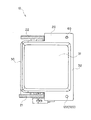
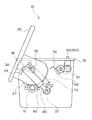
1 is an exploded perspective view of a lid opening / closing device, FIG. 2 is a side view of the opening / closing device showing a state in which the lid is closed, FIG. 3 is a front view of FIG. 2, and FIG. FIG. 5 is an enlarged view of the guide groove of the lid, FIG. 6 corresponds to FIG. 2, a side view of the opening / closing device showing a state where the closed lid is pushed in, and FIG. 7 corresponds to FIG. FIG. 8 corresponds to FIG. 2 and FIG. 9 corresponds to FIG. 2, and FIG. 9 corresponds to FIG. 2, and shows a state in the middle of closing the open lid. The side view of the switchgear which shows a state is each shown.
(Opening /
In the figure,
上記開閉装置10は、例えば、小物入れとして使用し、図示しないが、自動車のセンターコンソールに埋設状に固定される。
なお、開閉装置10の用途は、小物入れに限定されず、灰皿や、或いはコインケース等に使用しても良い。
また、開閉装置10の取付位置も、自動車のセンターコンソールに限定されず、自動車のインスツルメントパネル、ドアの内壁、ボディの内壁、シートの背面、肘掛け、或いはフロアー等でも良い。さらに、開閉装置10の取付位置は、自動車に限定されず、電車、船舶、事務機器、或いは家具等に取り付けても良い。
The opening /
The use of the opening /
Further, the attachment position of the opening /
上記開閉装置10は、図1〜4に示すように、大別すると、次のパーツを備える。
(1)ベース30
(2)リッド20
(3)ばね装置40
(4)ダンパー装置50
(5)クッション部材60
なお、開閉装置10のパーツは、上記した(1)〜(5)に限定されない。
(ベース30)
ベース30は、図1に示すように、上面に開口した開口部31を有する中空のケース状に形成されている。
As shown in FIGS. 1 to 4, the opening /
(1)
(2)
(3)
(4) Damper device 50
(5)
The parts of the opening /
(Base 30)
As shown in FIG. 1, the
ベース30には、図1に示すように、次の部位を有する。
なお、ベース30の部位は、次の(1)〜(5)に限定されない。
(1)フランジ32
フランジ32は、図1に示すように、開口部31の周囲から張り出すものである。
そして、フランジ32の左右両側には、図1に示すように、上下に貫通する貫通穴33〜34をそれぞれ設けている。左右の貫通穴33〜34のうち、図3に示すように、向かって左側の貫通穴33には、後述するプッシュロッド120の押圧部123が、上下方向にスライド可能に取り付けられる。また、左右の貫通穴33〜34のうち、向かって右側の貫通穴34には、後述するクッション部材60が取り付けられる。
As shown in FIG. 1, the
In addition, the site | part of the
(1)
As shown in FIG. 1, the
And as shown in FIG. 1, the through-holes 33-34 penetrated up and down are provided in the both right and left sides of the
(2)回転軸35
回転軸35は、左右一対設けられ、図1に示すように、ベース30の左右両側面から円筒形にそれぞれ突出している。左右の回転軸35は、図2に示すように、奥側に位置し、リッド20を開閉可能に支持するものである。
(3)揺動軸36
揺動軸36は、図1に示すように、ベース30の向かって左側の左側面から円筒形に突出している。揺動軸36は、図2に示すように、回転軸35に比較して手前側に位置し、後述するプッシュアーム100を揺動可能に支持するためのものである。
(2) Rotating
A pair of left and right
(3)
As shown in FIG. 1, the
(4)支持軸37
支持軸37は、図1に示すように、ベース30の左側面から円筒形に突出している。支持軸37は、図2に示すように、回転軸35及び揺動軸36の下側に位置し、後述する第1リンクアーム80を回転可能に支持するためのものである。
(5)ストッパー38
ストッパー38は、図1に示すように、ベース30の左側面から平面長円形に突出している。ストッパー38は、図7に示すように、後述するが、リッド20が開放する途中でピン91に係合し、ピン91をロック部26から始端部25に向かって移動するためのものである。
(リッド20)
リッド20は、図2に示すように、ベース30の左右の回転軸35に回転可能に支持され、開口部31を開閉するものである。
(4)
As shown in FIG. 1, the
(5)
As shown in FIG. 1, the
(Lid 20)
As shown in FIG. 2, the
なお、リッド20の開閉方向は、上下方向に限定されず、横方向、下向き、或いは斜め方向でも良い。
具体的には、リッド20には、図1に示すように、次の部位を有する。
なお、リッド20の部位は、次の(1)〜(4)に限定されない。
(1)ヒンジ部21〜22
ヒンジ部21〜22は、図1に示すように、リッド20の左右両側から一対延びている。
The opening / closing direction of the
Specifically, the
In addition, the site | part of the
(1) Hinge part 21-22
As shown in FIG. 1, the
(2)回転穴23
回転穴23は、図1に示すように、左右のヒンジ部21〜22のほぼ中央にそれぞれ設けられ、内外に貫通する円形にそれぞれ形成されている。そして、左右の回転穴23には、図1に示すように、ベース30の左右の両側面から突出する左右の回転軸35がそれぞれ挿入され、当該回転軸35を中心にリッド20は、ベース30に対して回転可能に支持される。
(2) Rotating
As shown in FIG. 1, the rotation holes 23 are provided at substantially the centers of the left and
(3)ガイド溝24
ガイド溝24は、図1に示すように、リッド20の向かって左側のヒンジ部21に設けられ、略V字形に屈曲して形成されている。そして、ガイド溝24には、図2に示すように、後述する第1リンクアーム80のピン91が挿入され、当該ピン91はガイド溝24に沿って移動する。
(3)
As shown in FIG. 1, the
また、ガイド溝24は、リッド20が開放位置(図8参照)から所定の角度、例えば45度(図9参照)、閉じられることで、ピン91を第1リンクアーム80から離れる方向に移動させ、これによりスプリング70を引っ張るためのものである。
すなわち、ガイド溝24は、リッド20の回転軸35と、第1リンクアーム80の支持軸37とを結ぶ線の延長線(図示せず)を境にピン91の移動を許容するものである。
The
That is, the
これに対し、ピン91は、前記延長線(図示せず)を境に、リッド20の自由端部から離れる奥側に移動することで、リッド20を開放するようにしている(図6〜7参照)。
一方、ガイド溝24は、リッド20が閉じた位置(図2参照)で、第1リンクアーム80の支持軸37から離れる方向に延び、例えば図5に示すように、支持軸37に近い始端部25と、支持軸37から遠く離れるとともに、略L字形に折れ曲がったロック部26とを備える。
On the other hand, the
On the other hand, the
(4)セクターギア27
セクターギア27は、図1に示すように、リッド20の左側のヒンジ部21に設けられ、円周の略1/4の円弧状に形成されている。そして、セクターギア27には、図2に示すように、後述する回転ダンパー51の制動ギアが噛み合う。
(ばね装置40)
ばね装置40は、図1に示すように、1本のスプリング70を中心に構成されている。
(4)
As shown in FIG. 1, the
(Spring device 40)
As shown in FIG. 1, the
上記1本のスプリング70は、図2に示すように、ベース30とリッド20との間、すなわち後述する第1リンクアーム80と第2リンクアーム90との間に掛け設けられている。
スプリング70は、リッド20が閉じた閉位置(図2参照)を行き過ぎた押込位置(図6参照)まで押し込まれることで引っ張られ、そのばね復元力により、リッド20を開放する方向に付勢するためのものである。
As shown in FIG. 2, the one
The
また、スプリング70は、ばね復元力により開放されたリッド20が所定の角度、例えば45度(図9参照)、閉じられることで再度、引っ張られ、そのばね復元力により、リッド20を閉じる方向に付勢するためのものである。
具体的には、ばね装置40は、上記した1本のスプリング70のほか、大別すると、次のパーツを備える。
The
Specifically, the
(1)第1リンクアーム80
(2)第2リンクアーム90
(3)スプリング70
(4)プッシュアーム100
(5)復帰ばね110
(6)プッシュロッド120
なお、ばね装置40のパーツは、上記した(1)〜(6)に限定されない。
(第1リンクアーム80)
第1リンクアーム80は、図1に示すように、支持軸37により一端部がベース30に回転可能に支持されるものである。
(1)
(2)
(3)
(4)
(5)
(6)
The parts of the
(First link arm 80)
As shown in FIG. 1, the
具体的には、第1リンクアーム80には、図1に示すように、次の部位を有する。
なお、第1リンクアーム80の部位は、次の(1)〜(2)に限定されない。
(1)支持穴81
支持穴81は、図1に示すように、第1リンクアーム80の一端部に形成され、図2に示すように、ベース30の左側面から突出した支持軸37に回転可能に支持される。
Specifically, the
In addition, the site | part of the
(1)
The
(2)ばね掛け部82
ばね掛け部82は、図1に示すように、支持穴81と同様に、第1リンクアーム80の一端部に形成され、スプリング70の一端部を掛け止めるためのものである。
(第2リンクアーム90)
第2リンクアーム90は、図1に示すように、一端部が第1リンクアーム80にスライド可能に支持されている。
(2)
As shown in FIG. 1, the
(Second link arm 90)
As shown in FIG. 1, one end of the
すなわち、第2リンクアーム90は、図1に示すように、一端部が開口され、他端部が閉塞された中空の角筒形に形成されている。そして、第2リンクアーム90の開口一端部から、第1リンクアーム80の他端部を挿入することで、第1リンクアーム80に対して、第2リンクアーム90をスライド可能としている。
また、第2リンクアーム90は、図1に示すように、他端部にピン91を有する。ピン91は、図2に示すように、前述したように、リッド20の左側のヒンジ部21に形成されたガイド溝24内にはまり込み、ガイド溝24に沿って移動する。
That is, as shown in FIG. 1, the
Further, the
ピン91は、前述した第1リンクアーム80の支持軸37とを結ぶ線の延長線(図示せず)を境に、リッド20の自由端部に接近する手前側に移動することで、リッド20を閉じるようにしている(図2及び図9参照)。
一方、第2リンクアーム90は、図2に示すように、第1リンクアーム80との間に掛け設けられたスプリング70のばね復元力により、第1リンクアーム80に接近する方向に付勢されるものである。
The
On the other hand, as shown in FIG. 2, the
すなわち、第2リンクアーム90のピン91の有る他端部には、図1に示すように、第1リンクアーム80のばね掛け部82と対向させて、スプリング70の一端部を掛け止めるためのばね掛け部92を形成している。そして、図2に示すように、第1リンクアーム80のばね掛け部82と、第2リンクアーム90のばね掛け部92とに、スプリング70の両端部を掛け止めている。
That is, the other end of the
一方、第2リンクアーム90には、図2に示すように、次の部位を有する。
なお、第2リンクアーム90の部位は、次の(1)に限定されない。
(1)ボス93
ボス93は、図2に示すように、第2リンクアーム90の長さの途中に位置し、ベース30のの左側面に対向する内側面から円柱形に突出するものである。ボス93は、図2に示すように、後述するプッシュアーム100の押上部102に当接する。
(プッシュアーム100)
プッシュアーム100は、図1に示すように、ベース30に支持され、リッド20が押込位置(図6参照)まで押し込まれることで、後述するプッシュロッド120を介して、第2リンクアーム90を第1リンクアーム80から離れる方向に移動させ、これによりスプリング70を引っ張るためのものである。
On the other hand, the
In addition, the site | part of the
(1)
As shown in FIG. 2, the
(Push arm 100)
As shown in FIG. 1, the
プッシュアーム100は、図6に示すように、第2リンクアーム90を第1リンクアーム80から離れる方向に移動させることで、ピン91を始端部25からロック部26に向かって移動するようにしている。
具体的には、プッシュアーム100には、図1に示すように、次の部位を有する。
なお、プッシュアーム100の部位は、次の(1)〜(3)に限定されない。
As shown in FIG. 6, the
Specifically, the
In addition, the site | part of the
(1)軸止部101
軸止部101は、図1に示すように、プッシュアーム100の長さの途中に位置し、ベース30、すなわちその左側面から突出した揺動軸36に、回転可能に支持されるものである。
(2)押上部102
押上部102は、図1及び図6に示すように、軸止部101を挟んだ一端部に位置し、第1リンクアーム80から離れる方向に第2リンクアーム90を押し上げるためのものである。
(1)
As shown in FIG. 1, the
(2)
As shown in FIGS. 1 and 6, the push-up
(3)連結軸103
連結軸103は、図1に示すように、軸止部101を挟んだ他端部に位置し、後述するプッシュロッド120に向かって円柱形に突出するものである。連結軸103は、図1〜2に示すように、後述するプッシュロッド120と連結するためのものである。
(復帰ばね110)
復帰ばね110は、プッシュアーム100とベース30との間に位置し、図6に示すように、リッド20の自由端部により、後述するプッシュロッド120が押し下げられることで、軸止部101を中心に回転したプッシュアーム100を復帰させるためのものである。
(プッシュロッド120)
プッシュロッド120には、次の部位を有する。
(3) Connecting
As shown in FIG. 1, the connecting
(Return spring 110)
The
(Push rod 120)
The
なお、プッシュロッド120の部位は、次の(1)〜(2)に限定されない。
(1)連結穴121
連結穴121は、図1に示すように、プッシュロッド120の一端部に形成され、内外に円形に貫通する。連結穴121には、図2に示すように、プッシュアーム100の連結軸103が挿入され、当該連結軸103を中心にプッシュロッド120は、プッシュアーム100に対して回転可能に支持される。
In addition, the site | part of the
(1) Connecting
As shown in FIG. 1, the connecting
(2)押圧部123
押圧部123は、図1に示すように、上記連結穴121から棒状に延びている。そして、押圧部123は、図2〜3に示すように、リッド20のフランジ32の左側の貫通穴33を通して、上方に向かって突出し、リッド20の自由端部により押し下げられるものである。
(ダンパー装置50)
ダンパー装置50は、図2に示すように、ベース30とリッド20との間に位置し、スプリング70のばね復元力により、リッド20に作用する回転力を減衰するためのものである。
(2) Pressing part 123
As shown in FIG. 1, the pressing portion 123 extends from the connecting
(Damper device 50)
As shown in FIG. 2, the damper device 50 is located between the base 30 and the
具体的には、ダンパー装置50は、図2に示すように、前述したリッド20の左側のヒンジ部21に設けられたセクターギア27のほか、次のパーツを備える。
なお、ダンパー装置50のパーツは、セクターギア27や、次の(1)に限定されない。例えば、回転ダンパー51に代えて、シリンダー型のエアーダンパーを使用しても良い。
(1)回転ダンパー51
回転ダンパー51には、オイル封入式のものが使用され、図2に示すように、ベース30の左側面に固定され、その制動ギアがセクターギア27に噛み合っている。
(クッション部材60)
クッション部材60は、例えばゴム製で、ベース30のフランジ32の右側の貫通穴34に取り付けられ、ベース30のフランジ32の上面から上方に向かって突出する。クッション部材60は、リッド20の自由端部の内面に弾性的に当接する。
(開閉装置10の使用方法)
上記した構成を備える開閉装置10は、次のように使用する。
Specifically, as shown in FIG. 2, the damper device 50 includes the following parts in addition to the
The parts of the damper device 50 are not limited to the
(1) Rotating
As the
(Cushion member 60)
The
(How to use switchgear 10)
The
まず、閉じたリッド20を開く際には、図6に示すように、リッド20の自由端部の上面を、ベース30に向かって押し下げれば良い。
リッド20を押し下げると、図6に示すように、その下面に押されて、プッシュロッド120の押圧部123が下降する。
プッシュロッド120が下降すると、図6に示すように、その連結穴121に挿入されたプッシュロッド120の連結軸103が下降する。
First, when the
When the
When the
プッシュロッド120の連結軸103の下降にともない、図6に示すように、ベース30の左側面から突出した揺動軸36を挟んで反対側に位置する押上部102が上昇する。
このため、プッシュロッド120の押上部102により、図6に示すように、第2リンクアーム90のボス93が押し上げられる。
第2リンクアーム90のボス93の上昇にともない、図6に示すように、第2リンクアーム90が第1リンクアーム80から離れる方向に移動し、これにより、スプリング70が引っ張られ、そのばね力を蓄積する。
As the connecting
Therefore, the
As the
このとき、第2リンクアーム90のピン91が、図6に示すように、ガイド溝24中を移動する。
すなわち、図2に示すように、ガイド溝24の支持軸37に近い始端部25に位置していたピン91が、図6に示すように、ロック部26に向かって移動し、やがてロック部26にはまり込んでロックされる。
At this time, the
That is, as shown in FIG. 2, the
その後、リッド20を押し下げる力を開放すると、リッド20は、図7〜8に示すように、スプリング70が短縮しようとするばね復元力により、開放する。
このとき、リッド20のセクターギア27とのかみ合いにより、図7〜8に示すように、回転ダンパー51の制動ギアが回転することで、回転ダンパー51の減衰力が作用し、リッド20は、ゆっくりと且つ静粛に開放する。
Thereafter, when the force that pushes down the
At this time, as shown in FIGS. 7 to 8 due to the meshing of the
一方、リッド20の開放する途中で、第2リンクアーム90のピン91が、図7に示すように、ベース30の左側面から突出したストッパー38に当接する。
このため、ガイド溝24のロック部26にはまり込んでいるピン91が、図7に示すように、始端部25に向かって移動する。そして、リッド20の開放位置では、図8に示すように、第2リンクアーム90のピン91は、ガイド溝24の始端部25に位置する。
On the other hand, while the
Therefore, the
一方、開放状態のリッド20を閉じる際には、図9に示すように、リッド20を45度、手で閉じれば良い。
このとき、リッド20の回転により、図9に示すように、ガイド溝24の位置が変位する。
このため、ガイド溝24にはまり込んでいるピン91が、ベース30の支持軸37から離れる方向に移動し、第2リンクアーム90は、図9に示すように、第1リンクアーム80から離れる方向に移動し、これにより、スプリング70が引っ張られ、そのばね力を蓄積する。
On the other hand, when the
At this time, the position of the
Therefore, the
なお、このとき、ガイド溝24の始端部25に位置していたピン91が、図示しないが、ロック部26に向かって少し移動する。
その後、リッド20から手を離すと、リッド20は、図9に示すように、スプリング70が短縮しようとするばね復元力により、閉じる。
このとき、リッド20のセクターギア27とのかみ合いにより、図9に示すように、回転ダンパー51の制動ギアが回転することで、回転ダンパー51の減衰力が作用し、リッド20は、ゆっくりと且つ静粛に閉じる。
At this time, the
Thereafter, when the hand is released from the
At this time, as shown in FIG. 9, due to the engagement of the
一方、リッド20が閉じた状態でも、スプリング70が若干引っ張られ、そのばね復元力により、リッド20は閉じる方向に付勢されている。
このため、車の振動等により、リッド20が不用意に開くことがない。
なお、車の振動等により、リッド20を開放する方向に力が更に作用しても、ガイド溝24の位置が変位することから、ピン91を介して第2リンクアーム90は、第1リンクアーム80から離れる方向に移動し、これにより、スプリング70が引っ張られる量が増加する。このため、仮にリッド20が少し開いても、スプリング70が短縮しようとするばね復元力により、リッド20が元通り閉じる。
On the other hand, even when the
For this reason, the
Even if a force further acts in the direction to open the
上記した理由から、本発明を実施するための最良の形態では、リッド20を閉じた状態にロックするための機構を敢えて設けなかったが、リッド20を閉じた状態にロックするための機構を設けても良い。リッド20を閉じた状態にロックするための機構を設けた場合には、悪路等の走行時のリッド20のバタ付きを防止することができる。
For the reasons described above, in the best mode for carrying out the present invention, a mechanism for locking the
10 開閉装置 20 リッド
21〜22 ヒンジ部 23 回転穴
24 ガイド溝 25 始端部
26 ロック部 27 セクターギア
30 ベース 31 開口部
32 フランジ 33〜34 貫通穴
35 回転軸 36 揺動軸
37 支持軸 38 ストッパー
40 ばね装置 50 ダンパー装置
51 回転ダンパー 60 クッション部材
70 スプリング 80 第1リンクアーム
81 支持穴 82 ばね掛け部
90 第2リンクアーム 91 ピン
92 ばね掛け部 93 ボス
100 プッシュアーム 101 軸止部
102 押上部 103 連結軸
110 復帰ばね 120 プッシュロッド
121〜22 連結穴 123 押圧部
10
21-22
24
26
30
32
35 Rotating
37
40 Spring device 50 Damper device
51
70
81
90
92
100
102 Push-up
110
121-22 Connecting hole 123 Pressing part
Claims (8)
前記ベースに回転軸を中心に回転可能に支持され、前記開口部を開閉するリッドと、
前記ベースと前記リッドとの間に掛け設けられ、前記リッドが閉じた閉位置を行き過ぎた押込位置まで押し込まれることで引っ張られ、そのばね復元力により、前記リッドを開放する方向に付勢し、前記ばね復元力により開放された前記リッドが所定の角度閉じられることで再度、引っ張られ、そのばね復元力により、前記リッドを閉じる方向に付勢するための1本のスプリングとを備えることを特徴とするリッドの開閉装置。 A base having an opening,
A lid that is rotatably supported by the base around a rotation axis, and that opens and closes the opening;
Hang between the base and the lid, the lid is pulled by being pushed to the pushed position that has passed the closed position closed, and is biased in the direction to open the lid by its spring restoring force, The lid opened by the spring restoring force is pulled again by being closed at a predetermined angle, and is provided with one spring for biasing the lid in the closing direction by the spring restoring force. The lid opening and closing device.
前記ベースと前記リッドとの間には、
支持軸により一端部がベースに回転可能に支持される第1リンクアームと、
一端部が前記第1リンクアームにスライド可能に支持され、他端部にピンを有し、前記第1リンクアームとの間に掛け設けられた前記スプリングのばね復元力により、前記第1リンクアームに接近する方向に付勢される第2リンクアームと、
前記ベースに支持され、前記リッドが前記押込位置まで押し込まれることで、前記第2リンクアームを前記第1リンクアームから離れる方向に移動させ、これにより前記スプリングを引っ張るためのプッシュアームと、
前記リッドに設けられ、前記ピンを移動可能にガイドするとともに、前記リッドが開放位置から所定の角度閉じられることで、前記ピンを前記第1リンクアームから離れる方向に移動させ、これにより前記スプリングを引っ張るためのガイド溝と
を備えていることを特徴とするリッドの開閉装置。 The lid opening and closing device according to claim 1,
Between the base and the lid,
A first link arm whose one end is rotatably supported by the base by a support shaft;
The first link arm is slidably supported by the first link arm, has a pin at the other end, and the spring restoring force of the spring provided between the first link arm and the first link arm. A second link arm biased in a direction approaching
A push arm that is supported by the base and moves the second link arm in a direction away from the first link arm by pushing the lid to the pushing position, thereby pulling the spring;
The pin is provided on the lid and guides the pin to be movable, and the lid is closed at a predetermined angle from the open position to move the pin in a direction away from the first link arm. A lid opening and closing device comprising a guide groove for pulling.
前記所定の角度は、
45度に設定されていることを特徴とするリッドの開閉装置。 The lid opening / closing device according to claim 1 or 2,
The predetermined angle is
A lid opening and closing device characterized by being set to 45 degrees.
前記ガイド溝は、
前記リッドの前記回転軸と、前記第1リンクアームの前記支持軸とを結ぶ線の延長線を境に前記ピンの移動を許容し、
前記ピンは、
前記延長線を境に、前記リッドの自由端部から離れる奥側に移動することで、前記リッドを開放するとともに、
前記延長線を境に、前記リッドの自由端部に接近する手前側に移動することで、前記リッドを閉じるようにしていることを特徴とするリッドの開閉装置。 The lid opening / closing device according to any one of claims 1 to 3,
The guide groove is
Allowing the pin to move on the boundary of an extension line connecting the rotation shaft of the lid and the support shaft of the first link arm;
The pin is
With the extension line as a boundary, by moving to the back side away from the free end of the lid, the lid is opened,
The lid opening and closing device characterized in that the lid is closed by moving to the near side approaching the free end of the lid with the extension line as a boundary.
前記ガイド溝は、
前記リッドが閉じた位置で、前記第1リンクアームの前記支持軸から離れる方向に延び、前記支持軸に近い始端部と、前記支持軸から遠く離れるとともに、折れ曲がったロック部とを備え、
前記プッシュアームは、
前記第2リンクアームを前記第1リンクアームから離れる方向に移動させることで、前記ピンを前記始端部から前記ロック部に向かって移動するようにしていることを特徴とするリッドの開閉装置。 In the lid opening and closing device according to any one of claims 1 to 4,
The guide groove is
The lid is closed, and extends in a direction away from the support shaft of the first link arm, and includes a start end portion close to the support shaft, a farther away from the support shaft, and a bent lock portion.
The push arm is
The lid opening and closing device characterized in that the pin is moved from the starting end toward the locking portion by moving the second link arm in a direction away from the first link arm.
前記ベースには、
前記リッドが開放する途中で前記ピンに係合し、前記ピンを前記ロック部から前記始端部に向かって移動するためのストッパーを設けていることを特徴とするリッドの開閉装置。 The lid opening / closing device according to any one of claims 1 to 5,
The base includes
A lid opening / closing device comprising a stopper that engages with the pin in the middle of opening of the lid and moves the pin from the lock portion toward the start end portion.
前記プッシュアームは、
その長さの途中に位置し、前記ベースに回転可能に支持される軸止部と、
前記軸止部を挟んだ一端部に位置し、前記リッドに向かって突出し、前記リッドの自由端部により押し下げられる押圧部と、
前記軸止部を挟んだ他端部に位置し、前記第1リンクアームから離れる方向に前記第2リンクアームを押し上げるための押上部とを備え、
前記プッシュアームと前記ベースとの間には、
前記リッドの自由端部により前記押圧部が押し下げられることで、前記軸止部を中心に回転した前記プッシュアームを復帰させるための復帰ばねを設けていることを特徴とするリッドの開閉装置。 The lid opening / closing device according to any one of claims 1 to 6,
The push arm is
A shaft stopper located in the middle of the length and rotatably supported by the base;
A pressing portion that is located at one end portion sandwiching the shaft stopping portion, protrudes toward the lid, and is pushed down by a free end portion of the lid;
A push-up portion for pushing up the second link arm in a direction away from the first link arm, located at the other end of the shaft stop portion;
Between the push arm and the base,
A lid opening / closing device comprising a return spring for returning the push arm rotated around the shaft stop when the pressing portion is pushed down by a free end portion of the lid.
前記ベースと前記リッドとの間には、
前記リッドに作用する回転力を減衰するためのダンパー装置を設けていることを特徴とするリッドの開閉装置。
The lid opening / closing device according to any one of claims 1 to 7,
Between the base and the lid,
A lid opening / closing device comprising a damper device for attenuating rotational force acting on the lid.
Priority Applications (4)
| Application Number | Priority Date | Filing Date | Title |
|---|---|---|---|
| JP2003422653A JP4293897B2 (en) | 2003-12-19 | 2003-12-19 | Lid opening and closing device |
| KR1020040104996A KR100598328B1 (en) | 2003-12-19 | 2004-12-13 | Lid opening/closing device |
| US11/012,232 US7451888B2 (en) | 2003-12-19 | 2004-12-16 | Lid opening and closing apparatus with mechanism for assisting opening and closing of lid |
| CNB2004101013645A CN100345730C (en) | 2003-12-19 | 2004-12-17 | Lid opening and closing apparatus |
Applications Claiming Priority (1)
| Application Number | Priority Date | Filing Date | Title |
|---|---|---|---|
| JP2003422653A JP4293897B2 (en) | 2003-12-19 | 2003-12-19 | Lid opening and closing device |
Publications (2)
| Publication Number | Publication Date |
|---|---|
| JP2005178593A true JP2005178593A (en) | 2005-07-07 |
| JP4293897B2 JP4293897B2 (en) | 2009-07-08 |
Family
ID=34675326
Family Applications (1)
| Application Number | Title | Priority Date | Filing Date |
|---|---|---|---|
| JP2003422653A Expired - Fee Related JP4293897B2 (en) | 2003-12-19 | 2003-12-19 | Lid opening and closing device |
Country Status (4)
| Country | Link |
|---|---|
| US (1) | US7451888B2 (en) |
| JP (1) | JP4293897B2 (en) |
| KR (1) | KR100598328B1 (en) |
| CN (1) | CN100345730C (en) |
Cited By (4)
| Publication number | Priority date | Publication date | Assignee | Title |
|---|---|---|---|---|
| JP2007297012A (en) * | 2006-05-02 | 2007-11-15 | Advanex Inc | Opening/closing mechanism |
| WO2011043356A1 (en) * | 2009-10-08 | 2011-04-14 | 株式会社ニフコ | Lid opening and closing device |
| JP2020517850A (en) * | 2017-04-21 | 2020-06-18 | ドンタイ・ハードウェア・プレシジョン・(ホンコン)・リミテッド | Mechanism to move furniture doors |
| JP2021098470A (en) * | 2019-12-23 | 2021-07-01 | 本田技研工業株式会社 | Storage part structure of saddle-riding type vehicle |
Families Citing this family (44)
| Publication number | Priority date | Publication date | Assignee | Title |
|---|---|---|---|---|
| US7613741B2 (en) * | 2002-08-01 | 2009-11-03 | Oracle International Corporation | Utilizing rules in a distributed information sharing system |
| JP4615269B2 (en) * | 2004-08-18 | 2011-01-19 | 株式会社ニフコ | Acceleration / deceleration mechanism and vehicle accessory case equipped with the acceleration / deceleration mechanism |
| US7152898B2 (en) * | 2005-01-06 | 2006-12-26 | Lear Corporation | System and method for reducing vehicle noise |
| JP4703287B2 (en) * | 2005-06-24 | 2011-06-15 | 株式会社ニフコ | Door opening and closing device |
| KR100982711B1 (en) * | 2005-06-29 | 2010-09-17 | 가부시키가이샤 니포 코포레이션 | Method of dust suppression disposal |
| US7621419B2 (en) * | 2005-08-05 | 2009-11-24 | Nifco Inc. | Door operating mechanism and unit |
| DE102005044436B4 (en) * | 2005-09-16 | 2009-02-12 | Lisa Dräxlmaier GmbH | Center console for a vehicle |
| JP2007145300A (en) * | 2005-11-30 | 2007-06-14 | Toyoda Gosei Co Ltd | Storage body |
| JP4785574B2 (en) * | 2006-03-15 | 2011-10-05 | キヤノン株式会社 | Image forming apparatus and opening / closing mechanism |
| KR100805476B1 (en) | 2006-10-31 | 2008-02-20 | 현대자동차주식회사 | Opening and shutting structure of switch cover for automotive rear armrest |
| KR100825402B1 (en) * | 2007-01-26 | 2008-04-29 | 쌍용자동차 주식회사 | Opening and closing device of glovebox for automobile |
| JP5108358B2 (en) * | 2007-04-06 | 2012-12-26 | 株式会社ニフコ | Lid opening / closing device |
| FR2916749B1 (en) * | 2007-06-04 | 2009-09-11 | Vygi Sarl | OPENING / CLOSING SYSTEM ASSISTED WITH A COVER AND A WASTE CONTAINER HAVING SUCH A COVER |
| US8141759B2 (en) * | 2008-01-08 | 2012-03-27 | Toyota Motor Engineering & Manufacturing North America, Inc. | Container assembly for a motor vehicle |
| US7731254B2 (en) * | 2008-01-09 | 2010-06-08 | Toyota Motor Engineering & Manufacturing North America, Inc. | Motor vehicle center console assembly having a container assembly with a flush door |
| JP5134388B2 (en) | 2008-02-14 | 2013-01-30 | 株式会社ニフコ | Lid device |
| US8177445B2 (en) * | 2008-04-01 | 2012-05-15 | Hewlett-Packard Development Company, L.P. | Over-center mechanism |
| JP2009263944A (en) * | 2008-04-24 | 2009-11-12 | Nifco Inc | Rotary mechanism |
| WO2010000951A1 (en) * | 2008-07-01 | 2010-01-07 | Vygi | System for the aided closing/opening of a lid, and waste container provided with such a lid |
| US8079446B2 (en) * | 2008-09-30 | 2011-12-20 | Nifco Inc. | Operational mechanism for movable body |
| JP5254151B2 (en) * | 2008-09-30 | 2013-08-07 | 株式会社ニフコ | Actuation mechanism of moving body |
| US20100200784A1 (en) * | 2009-02-12 | 2010-08-12 | Charles James Turner | Bellowphragm actuated fluid control swing valve |
| JP5193115B2 (en) | 2009-04-01 | 2013-05-08 | 株式会社ニフコ | Operating mechanism of movable body |
| US20110215606A1 (en) * | 2010-03-08 | 2011-09-08 | Nissan Technical Center North America, Inc. | Console lid friction hinge |
| CN102730294B (en) * | 2011-04-12 | 2016-05-04 | 江森自控(中国)投资有限公司 | For rising the swinging arm device of container lid and thering is lid and the container of this swinging arm device |
| KR101237167B1 (en) * | 2011-05-19 | 2013-02-25 | 주식회사 니프코코리아 | a console box |
| US8523010B2 (en) * | 2011-05-31 | 2013-09-03 | Hewlett-Packard Development Company, L.P. | Bistable cover assemblies |
| JP5965166B2 (en) * | 2012-03-14 | 2016-08-03 | 株式会社ニフコ | Storage device |
| CN104057888B (en) * | 2014-06-24 | 2016-06-15 | 延锋汽车饰件系统有限公司 | Automobile glove box |
| JP6570337B2 (en) * | 2014-07-17 | 2019-09-04 | キヤノン株式会社 | Image forming apparatus and damper apparatus |
| JP6413923B2 (en) * | 2015-05-19 | 2018-10-31 | 豊田合成株式会社 | Storage device with lid |
| DE102015225519A1 (en) * | 2015-12-16 | 2017-06-22 | Faurecia Innenraum Systeme Gmbh | Lid for a storage compartment for use in a vehicle interior |
| CN109153349B (en) * | 2016-05-18 | 2021-09-14 | 上海延锋金桥汽车饰件系统有限公司 | Console assembly for a vehicle interior |
| US10486568B2 (en) * | 2017-06-14 | 2019-11-26 | Gulfstream Aerospace Corporation | Seat assemblies including an armrest with an armrest lid and a hinge arrangement |
| CN107585421B (en) * | 2017-09-05 | 2019-05-21 | 安徽省无为天成纺织有限公司 | A kind of textile storage box |
| CN108128578A (en) * | 2018-01-28 | 2018-06-08 | 周建华 | A kind of dustbin with rubbish squeeze function |
| US11572723B2 (en) | 2019-02-27 | 2023-02-07 | Shanghai Yanfeng Jinqiao Automotive Triim Systems Co. Ltd. | Vehicle interior component |
| CN110040402A (en) * | 2019-05-09 | 2019-07-23 | 周建华 | A kind of waste bin |
| CN110040349B (en) * | 2019-05-15 | 2024-02-20 | 联特科技有限公司 | Flip buffering formula lid closes garbage bin |
| CN110547503B (en) * | 2019-08-27 | 2022-04-29 | 宁波帅特龙集团有限公司 | Ashtray for vehicle |
| CN110696725B (en) * | 2019-10-15 | 2021-06-04 | 宁波帅特龙集团有限公司 | Back-lifting device when cover plate is closed |
| CN113017453B (en) * | 2021-03-04 | 2022-04-22 | 深圳市康灵盾智能厨具设备有限公司 | Push away and cover device and condiment platform |
| CN113232976A (en) * | 2021-04-14 | 2021-08-10 | 刘泰湖 | Hardware material storage box |
| CN115420144A (en) * | 2022-08-30 | 2022-12-02 | 上海机电工程研究所 | Electromagnetic opening type cover opening device with self-locking function and cover opening device combination |
Citations (5)
| Publication number | Priority date | Publication date | Assignee | Title |
|---|---|---|---|---|
| JPH0635151U (en) * | 1992-10-09 | 1994-05-10 | 株式会社ホンダアクセス | Container with lid |
| JPH0737812U (en) * | 1993-12-24 | 1995-07-14 | 株式会社ニフコ | Vehicle accessory storage device |
| JP2000272426A (en) * | 1999-03-23 | 2000-10-03 | Araco Corp | Console box |
| JP2003002059A (en) * | 2001-06-19 | 2003-01-08 | Meiwa Kogyo Kk | Storage device for vehicle |
| JP2003118467A (en) * | 2001-10-11 | 2003-04-23 | Nifco Inc | Brake mechanism of opening/closing member, and cup holder and automobile door with the same |
Family Cites Families (13)
| Publication number | Priority date | Publication date | Assignee | Title |
|---|---|---|---|---|
| DE3720815A1 (en) * | 1986-07-04 | 1988-01-14 | Volkswagen Ag | Arrangement for decelerating the opening movement of a tiltable lid for a storage compartment |
| JP2594955Y2 (en) * | 1993-03-15 | 1999-05-24 | 株式会社ニフコ | Accessory storage device for vehicles |
| JPH08184237A (en) * | 1994-12-28 | 1996-07-16 | Nifco Inc | Lock mechanism of turning cover |
| JP3209027B2 (en) * | 1995-01-20 | 2001-09-17 | 三菱自動車工業株式会社 | Lid opening and closing device |
| JP3053540B2 (en) * | 1995-02-01 | 2000-06-19 | 本田技研工業株式会社 | Cup holder |
| JP3314903B2 (en) * | 1995-07-04 | 2002-08-19 | 株式会社ニフコ | Vehicle accessory storage device |
| JPH09142221A (en) * | 1995-11-24 | 1997-06-03 | Kanto Auto Works Ltd | Opening/closing mechanism for lid body |
| JP4028607B2 (en) * | 1996-07-24 | 2007-12-26 | 富山化学工業株式会社 | Novel cephalosporin derivatives or salts thereof |
| FR2752792B1 (en) * | 1996-09-03 | 1998-11-13 | Peugeot | GLOVE BOX, PARTICULARLY FOR MOTOR VEHICLES |
| US5971463A (en) * | 1998-07-30 | 1999-10-26 | Becker Group Europe Gmbh | Receptacle, such as an ashtray, glove compartment or the like for vehicles |
| JP2000272428A (en) * | 1999-03-25 | 2000-10-03 | Calsonic Kansei Corp | Lid body opening/closing mechanism of article pocket for vehicle |
| JP3833925B2 (en) * | 2001-10-29 | 2006-10-18 | 株式会社ニフコ | Door body opening / closing mechanism and opening / closing device using the same |
| KR100636964B1 (en) * | 2003-10-21 | 2006-10-19 | 가부시키가이샤 니프코 | Moving device |
-
2003
- 2003-12-19 JP JP2003422653A patent/JP4293897B2/en not_active Expired - Fee Related
-
2004
- 2004-12-13 KR KR1020040104996A patent/KR100598328B1/en not_active IP Right Cessation
- 2004-12-16 US US11/012,232 patent/US7451888B2/en not_active Expired - Fee Related
- 2004-12-17 CN CNB2004101013645A patent/CN100345730C/en not_active Expired - Fee Related
Patent Citations (5)
| Publication number | Priority date | Publication date | Assignee | Title |
|---|---|---|---|---|
| JPH0635151U (en) * | 1992-10-09 | 1994-05-10 | 株式会社ホンダアクセス | Container with lid |
| JPH0737812U (en) * | 1993-12-24 | 1995-07-14 | 株式会社ニフコ | Vehicle accessory storage device |
| JP2000272426A (en) * | 1999-03-23 | 2000-10-03 | Araco Corp | Console box |
| JP2003002059A (en) * | 2001-06-19 | 2003-01-08 | Meiwa Kogyo Kk | Storage device for vehicle |
| JP2003118467A (en) * | 2001-10-11 | 2003-04-23 | Nifco Inc | Brake mechanism of opening/closing member, and cup holder and automobile door with the same |
Cited By (7)
| Publication number | Priority date | Publication date | Assignee | Title |
|---|---|---|---|---|
| JP2007297012A (en) * | 2006-05-02 | 2007-11-15 | Advanex Inc | Opening/closing mechanism |
| WO2011043356A1 (en) * | 2009-10-08 | 2011-04-14 | 株式会社ニフコ | Lid opening and closing device |
| JP2011079457A (en) * | 2009-10-08 | 2011-04-21 | Honda Motor Co Ltd | Lid opening/closing device |
| JP2020517850A (en) * | 2017-04-21 | 2020-06-18 | ドンタイ・ハードウェア・プレシジョン・(ホンコン)・リミテッド | Mechanism to move furniture doors |
| JP7263668B2 (en) | 2017-04-21 | 2023-04-25 | グワンドン・ドンタイ・ハードウェア・プレシジョン・マニュファクチャリング・カンパニー・リミテッド | Mechanism for moving furniture doors |
| JP2021098470A (en) * | 2019-12-23 | 2021-07-01 | 本田技研工業株式会社 | Storage part structure of saddle-riding type vehicle |
| JP7177766B2 (en) | 2019-12-23 | 2022-11-24 | 本田技研工業株式会社 | Saddle type vehicle storage structure |
Also Published As
| Publication number | Publication date |
|---|---|
| US20050133507A1 (en) | 2005-06-23 |
| CN1629049A (en) | 2005-06-22 |
| CN100345730C (en) | 2007-10-31 |
| KR20050062387A (en) | 2005-06-23 |
| JP4293897B2 (en) | 2009-07-08 |
| US7451888B2 (en) | 2008-11-18 |
| KR100598328B1 (en) | 2006-07-10 |
Similar Documents
| Publication | Publication Date | Title |
|---|---|---|
| JP4293897B2 (en) | Lid opening and closing device | |
| US8376300B2 (en) | Apparatus with a rotating body | |
| JP4912318B2 (en) | Retraction mechanism | |
| US6019334A (en) | Cup holder with divided lid portions | |
| US20070096489A1 (en) | Hinge structure of glove box for vehicle | |
| JP5262689B2 (en) | Door opening / closing structure and door opening / closing device | |
| JP4875875B2 (en) | Door closing device | |
| JP2006232262A (en) | Hinge device of console lid, and console having the same | |
| WO2012128156A1 (en) | Display device | |
| JP4283465B2 (en) | Retractable hook device | |
| JP5016350B2 (en) | Vehicle storage device | |
| JP2006264513A (en) | Storage section structure of vehicle | |
| JP2007099180A (en) | Vehicular storage device | |
| JP2006291548A (en) | Free stop mechanism of self-closing type slide door | |
| JP2004146580A (en) | Switching device of opening and closing door, and liquid crystal projector using the same | |
| JP2009202846A (en) | Storing device in vehicle | |
| JP2007035744A (en) | Panel opening and closing mechanism | |
| JP2005036535A (en) | Outside handle device of door for vehicle | |
| JP2014040711A (en) | Vehicle side part structure | |
| JP2011190684A (en) | Door closing device | |
| JP3251982B2 (en) | Container support device | |
| JP2530293Y2 (en) | Grab compartment door opening and closing mechanism | |
| JP2001039200A (en) | On-vehicle cup holder | |
| JP2007145135A (en) | Storage box for automobile | |
| JP3926085B2 (en) | Door lock device for automobile |
Legal Events
| Date | Code | Title | Description |
|---|---|---|---|
| A621 | Written request for application examination |
Free format text: JAPANESE INTERMEDIATE CODE: A621 Effective date: 20061101 |
|
| A977 | Report on retrieval |
Free format text: JAPANESE INTERMEDIATE CODE: A971007 Effective date: 20080908 |
|
| A131 | Notification of reasons for refusal |
Free format text: JAPANESE INTERMEDIATE CODE: A131 Effective date: 20081009 |
|
| A521 | Request for written amendment filed |
Free format text: JAPANESE INTERMEDIATE CODE: A523 Effective date: 20081205 |
|
| TRDD | Decision of grant or rejection written | ||
| A01 | Written decision to grant a patent or to grant a registration (utility model) |
Free format text: JAPANESE INTERMEDIATE CODE: A01 Effective date: 20090402 |
|
| A01 | Written decision to grant a patent or to grant a registration (utility model) |
Free format text: JAPANESE INTERMEDIATE CODE: A01 |
|
| A61 | First payment of annual fees (during grant procedure) |
Free format text: JAPANESE INTERMEDIATE CODE: A61 Effective date: 20090407 |
|
| FPAY | Renewal fee payment (event date is renewal date of database) |
Free format text: PAYMENT UNTIL: 20120417 Year of fee payment: 3 |
|
| R150 | Certificate of patent or registration of utility model |
Free format text: JAPANESE INTERMEDIATE CODE: R150 |
|
| FPAY | Renewal fee payment (event date is renewal date of database) |
Free format text: PAYMENT UNTIL: 20120417 Year of fee payment: 3 |
|
| FPAY | Renewal fee payment (event date is renewal date of database) |
Free format text: PAYMENT UNTIL: 20130417 Year of fee payment: 4 |
|
| FPAY | Renewal fee payment (event date is renewal date of database) |
Free format text: PAYMENT UNTIL: 20130417 Year of fee payment: 4 |
|
| FPAY | Renewal fee payment (event date is renewal date of database) |
Free format text: PAYMENT UNTIL: 20130417 Year of fee payment: 4 |
|
| LAPS | Cancellation because of no payment of annual fees |