JP2005161237A - Raw material introduction part of air flow type fine powder crusher - Google Patents
Raw material introduction part of air flow type fine powder crusher Download PDFInfo
- Publication number
- JP2005161237A JP2005161237A JP2003405634A JP2003405634A JP2005161237A JP 2005161237 A JP2005161237 A JP 2005161237A JP 2003405634 A JP2003405634 A JP 2003405634A JP 2003405634 A JP2003405634 A JP 2003405634A JP 2005161237 A JP2005161237 A JP 2005161237A
- Authority
- JP
- Japan
- Prior art keywords
- raw material
- rotor blade
- casing
- region
- airflow
- Prior art date
- Legal status (The legal status is an assumption and is not a legal conclusion. Google has not performed a legal analysis and makes no representation as to the accuracy of the status listed.)
- Granted
Links
Images
Abstract
Description
本発明は、農産物や鉱物等の各種原料を粉砕するために用いられる気流式微粉砕機の原料投入部の形状に関するものである。 The present invention relates to the shape of a raw material charging portion of an airflow fine pulverizer used for pulverizing various raw materials such as agricultural products and minerals.
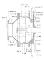
従来、農産物や鉱物等の各種原料を粉砕するために気流式微粉砕機が用いられている。この気流式微粉砕機は、図3に示すように、ケーシング10が投入側ケーシング13と、センターケーシング14と排出側ケーシング15とで構成されており、このケーシング10の内部には、投入側ケーシング13を貫通するシャフト16の前端(図3上、左端)に、第一回転翼11と第二回転翼12とが所定距離互いに離隔した状態で取付けられている。シャフト16はフレーム17によりベアリング(図示略)を介して回転自在に支持されている。シャフト16の後端にはモータ(図示略)が設けられ、シャフト16に回転を与える。
Conventionally, an airflow type fine grinder has been used to grind various raw materials such as agricultural products and minerals. As shown in FIG. 3, in this airflow type fine pulverizer, the
センターケーシング14は円筒形で、第一回転翼11と第二回転翼12の間に粉砕領域が形成されている。
投入側ケーシング13には、シャフト16に対して垂直な方向に原料を投入する原料投入部18が設けられている。また、センターケーシング14の後端部から後方に向けて径が漸減するテーパー壁19、テーパー壁19の後端にシャフト16に対して垂直な垂壁20が設けられておりセンターケーシング14の第一回転翼11から投入側ケーシング13の垂壁20までの間に亙って旋回領域が形成されている。テーパー壁19には原料供給口21が開口しており、旋回領域の後部のテーパー状の部分が、原料を原料供給口21から第一回転翼11側へ円滑に導入するための導入部となっている。
The center casing 14 has a cylindrical shape, and a pulverization region is formed between the first rotary blade 11 and the second rotary blade 12.
The
排出側ケーシング15は、前方に向けて径が漸減するテーパー壁22を有しており、前端部には排出口23が開口している。この排出口23には、吸引管を介して吸引ファンが接続される。
第一回転翼11と第二回転翼12は、ボス25、26の周囲に複数個の羽根27、28が放射状に設けられており、シャフト16の回転によって回転しケーシング10内に旋回する気流を生じさせる。なお、第一回転翼11の羽根27は、原料を旋回領域から粉砕領域へ導入しやすくするために、旋回のみでなく前方への推力も与える気流を生じさせる形状となっている。
The discharge side casing 15 has a tapered wall 22 whose diameter gradually decreases toward the front, and a discharge port 23 is opened at the front end. A suction fan is connected to the discharge port 23 via a suction pipe.
The first rotor blade 11 and the second rotor blade 12 are provided with a plurality of blades 27, 28 radially around the bosses 25, 26. The first rotor blade 11 and the second rotor blade 12 are rotated by the rotation of the shaft 16 and rotate in the
第二回転翼12には、羽根28の先端部に排出側ケーシング15のテーパー壁22に対向する傾斜面29が設けられており、第二回転翼12と排出側ケーシング15との間およびその前方のテーパー壁22に沿って分級領域が形成されている。
原料投入部18から投入された原料は、原料供給口21を通って投入側ケーシング13の旋回領域内に入り、旋回領域で旋回する気流によって旋回し、遠心力により半径方向外側に向かう流れが与えられて、原料の密度は中心部が低く外周部が高くなる。また、吸引ファンによって排出口23側へ吸引され、旋回領域と粉砕領域との間には差圧が生じる。
The second rotary blade 12 is provided with an inclined surface 29 facing the tapered wall 22 of the discharge side casing 15 at the tip of the blade 28, and between the second rotary blade 12 and the discharge side casing 15 and in front thereof. A classification region is formed along the tapered wall 22.
The raw material charged from the raw
この差圧と第一回転翼11で生じる気流の前方への推力によって、旋回領域内の原料はテーパー壁19に沿って徐々に導入部から第一回転翼11側に向かって移動する。旋回する原料の周速は原料供給口21から第一回転翼11側に向かって徐々に大きくなり、第一回転翼11付近では周速は粉砕領域の周速と略等しくなる。
旋回する原料は、旋回領域である程度滞留したのち差圧により第一回転翼11の羽根27の間を通って粉砕領域に入り、気流によって旋回する。ここで原料は粒子径の大きなもの程大きい遠心力が作用して周速の速い半径方向外周側に集まり、主として粒子同士の摩砕により、また粒子同士の衝突による破砕も生じて粉砕される。
Due to the differential pressure and the forward thrust of the air flow generated by the first rotary blade 11, the raw material in the swirl region gradually moves from the introduction portion toward the first rotary blade 11 along the
The swirling raw material stays to some extent in the swirl region, then enters between the blades 27 of the first rotary blade 11 by the differential pressure, enters the pulverization region, and swirls by the airflow. Here, the larger the particle size, the larger the particle diameter, the larger the centrifugal force acts, and the material gathers on the outer peripheral side in the radial direction where the peripheral speed is faster, and is pulverized mainly by grinding of the particles.
また、粉砕された原料のなかで粒子径が小さく質量の小さい粒子ほど圧力の低い第二回転翼12の回転中心近傍に集まり、吸引ファンで吸引されて排出口23から空気とともに排出され後段の捕集手段により粉砕製品として捕集される。粒子径が大きく質量の大きい粒子は、吸引された空気に随伴せず、テーパー壁22に沿った分級領域の外周部に生じる後方への戻り気流によって粉砕領域に戻る(例えば特許文献1参照)。 Further, among the pulverized raw materials, particles having a smaller particle diameter and smaller mass gather in the vicinity of the rotation center of the second rotor blade 12 having a lower pressure, and are sucked by a suction fan and discharged together with air from the discharge port 23. It is collected as a pulverized product by the collecting means. Particles having a large particle diameter and a large mass do not accompany the sucked air, and return to the pulverization region by a backward airflow generated at the outer periphery of the classification region along the tapered wall 22 (see, for example, Patent Document 1).
この気流式微粉砕機では、原料は、原料供給口21を通って投入側ケーシング13の旋回領域内に入り、旋回領域で旋回する気流によって旋回し、原料の分布は遠心力により投入側ケーシング13の半径方向外周側が密になる。原料を前方へ移動させる推力は、第一回転翼11から遠いため原料供給口21では小さい。
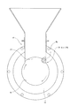
このため、例えば、大豆のような油分を含有する原料を粉砕する場合には、図4に示すように、テーパー壁19に開口した原料供給口21の旋回気流と対向する側のエッジ部30に粉砕半ばの原料Ms(以下、原料Msとする)が付着し堆積する現象が発生する。原料Msが堆積し成長すると、原料の供給が阻害され円滑に旋回気流を発生させることができなくなり、気流式微粉砕機は安定した破砕が行えない。
For this reason, for example, when pulverizing a raw material containing oil such as soybean, as shown in FIG. 4, the raw
本発明は、従来の気流式微粉砕機における上記問題を解決するものであって、テーパー壁に開口した原料供給口の旋回気流と対向し原料が堆積する側のエッジ部(原料堆積側エッジ部)に粉砕半ばの原料が堆積し成長するのを防止する気流式微粉砕機の原料投入部を提供することを目的とする。 The present invention solves the above-mentioned problem in the conventional airflow type fine pulverizer, and is the edge portion on the side where the raw material is deposited facing the swirling airflow of the raw material supply port opened in the tapered wall (raw material deposition side edge portion) An object of the present invention is to provide a raw material charging unit for an airflow type fine pulverizer that prevents the raw material in the middle of pulverization from accumulating and growing.
本発明では、ケーシング内に第一回転翼と第二回転翼とを所定距離互いに離隔して設け、ケーシング内の第一回転翼の後方に旋回領域、第一回転翼と第二回転翼との間に粉砕領域を形成し、ケーシングに粉砕領域から前方に向けて径が漸減するテーパー壁を設け、第二回転翼にテーパー壁に対向する傾斜面を設けてテーパー壁と傾斜面との間に分級隙間を形成し、原料投入部から投入される原料を第一回転翼及び第二回転翼の回転で発生させる旋回気流により微粉砕する気流式微粉砕機において、原料投入部を前記ケーシングの旋回領域の後部に開口する原料供給口の原料堆積側エッジ部に向けて原料を投入するよう構成することにより上記課題を解決している。 In the present invention, the first rotor blade and the second rotor blade are provided in the casing so as to be separated from each other by a predetermined distance, and the swirl region, the first rotor blade and the second rotor blade are disposed behind the first rotor blade in the casing. A crushing region is formed in between, a taper wall whose diameter gradually decreases from the crushing region toward the front is provided in the casing, and an inclined surface facing the taper wall is provided in the second rotary blade, and the taper wall and the inclined surface are provided. In an airflow type fine pulverizer that forms a classification gap and finely pulverizes the raw material charged from the raw material charging portion with the swirling airflow generated by the rotation of the first rotary blade and the second rotary blade, the raw material charging portion is the swirl region of the casing The above-described problem is solved by configuring the raw material supply port to open toward the raw material deposition side edge portion of the raw material supply port.
本発明の気流式微粉砕機の原料投入部では、原料が原料供給口の原料堆積側エッジ部に向けて投入されるので、投入された原料が原料堆積側エッジ部に堆積した原料と衝突し、原料の堆積を破壊して成長を阻止することができる。
また、原料供給口の原料堆積側エッジ部を曲面とすることで、原料堆積側エッジ部へ原料が堆積し難くなり、原料の堆積の破壊がより容易になる。
In the raw material charging part of the airflow type fine pulverizer of the present invention, since the raw material is charged toward the raw material deposition side edge part of the raw material supply port, the charged raw material collides with the raw material deposited on the raw material deposition side edge part, The deposition of raw materials can be destroyed to prevent growth.
Further, by forming the material deposition side edge portion of the material supply port into a curved surface, it becomes difficult to deposit the material on the material deposition side edge portion, and the deposition of the material is more easily broken.
本発明の気流式微粉砕機の原料投入部では、原料堆積側エッジ部に堆積した原料を破壊して成長を阻止することができる。 In the raw material charging portion of the airflow type fine pulverizer of the present invention, the raw material deposited on the raw material deposition side edge portion can be destroyed to prevent growth.
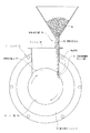
図1は本発明の実施の形態を示す気流式微粉砕機の原料投入部の垂直断面図である。
気流式微粉砕機の構成は、基本的には図3に示すものと同様である。即ち、ケーシング10が投入側ケーシング13と、センターケーシング14と排出側ケーシング15とで構成されており、このケーシング10の内部には、投入側ケーシング13を貫通するシャフト16の前端(図3上、左端)に、第一回転翼11と第二回転翼12とが所定距離互いに離隔した状態で取付けられている。シャフト16はフレーム17によりベアリング(図示略)を介して回転自在に支持されている。シャフト16の後端にはモータ(図示略)が設けられ、シャフト16に回転を与える。
FIG. 1 is a vertical sectional view of a raw material charging portion of an airflow type fine pulverizer showing an embodiment of the present invention.
The configuration of the airflow type fine pulverizer is basically the same as that shown in FIG. That is, the
投入側ケーシング13には、シャフト16に対して垂直な方向に原料を投入する原料投入部18が設けられている。また、センターケーシング14の後端部から後方に向けて径が漸減するテーパー壁19、テーパー壁19の後端にシャフト16に対して垂直な垂壁20が設けられておりセンターケーシング14の第一回転翼11から投入側ケーシング13の垂壁20までの間に亙って旋回領域が形成されている。テーパー壁19には原料供給口21が開口しており、旋回領域の後部のテーパー状の部分が、原料を原料供給口21から第一回転翼11側へ円滑に導入するための導入部となっている。
The
排出側ケーシング15は、前方に向けて径が漸減するテーパー壁22を有しており、前端部には排出口23が開口している。この排出口23には、吸引管を介して吸引ファンが接続される。
第一回転翼11と第二回転翼12は、ボス25、26の周囲に複数個の羽根27、28が放射状に設けられており、シャフト16の回転によって回転しケーシング10内に旋回する気流を生じさせる。なお、第一回転翼11の羽根27は、原料を旋回領域から粉砕領域へ導入しやすくするために、旋回のみでなく前方への推力も与える気流を生じさせる形状となっている。
The discharge side casing 15 has a tapered wall 22 whose diameter gradually decreases toward the front, and a discharge port 23 is opened at the front end. A suction fan is connected to the discharge port 23 via a suction pipe.
The first rotor blade 11 and the second rotor blade 12 are provided with a plurality of blades 27, 28 radially around the bosses 25, 26. The first rotor blade 11 and the second rotor blade 12 are rotated by the rotation of the shaft 16 and rotate in the
第二回転翼12には、羽根28の先端部に排出側ケーシング15のテーパー壁22に対向する傾斜面29が設けられており、第二回転翼12と排出側ケーシング15との間およびその前方のテーパー壁22に沿ってに分級領域が形成されている。
なお、原料供給口21と第一回転翼11の間や、第一回転翼11と第二回転翼12との間には、必要に応じて補助的な回転翼を設けることも可能である。
原料投入部18から投入された原料は、原料供給口21を通って投入側ケーシング13の旋回領域内に入り、旋回領域で旋回する気流によって旋回し、遠心力により半径方向外側に向かう流れが与えられて、原料の密度は中心部が低く外周部が高くなる。また、吸引ファンによって排出口23側へ吸引され、導入領域と旋回領域と粉砕領域との間には差圧が生じる。
The second rotary blade 12 is provided with an inclined surface 29 facing the tapered wall 22 of the discharge side casing 15 at the tip of the blade 28, and between the second rotary blade 12 and the discharge side casing 15 and in front thereof. A classification region is formed along the tapered wall 22.
In addition, it is also possible to provide an auxiliary rotor blade between the raw
The raw material charged from the raw
この差圧と第一回転翼11で生じる気流の前方への推力によって、旋回領域内の原料はテーパー壁19に沿って徐々に導入部から第一回転翼11側に向かって移動する。旋回する原料の周速は原料投入口21から第一回転翼11側に向かって徐々に大きくなり、第一回転翼11付近では周速は粉砕領域の周速と略等しくなる。
旋回する原料は、旋回領域である程度滞留したのち差圧により第一回転翼11の羽根27の間を通って粉砕領域に入り、気流によって旋回する。ここで原料は粒子径の大きなもの程大きい遠心力が作用して周速の速い半径方向外周側に集まり、主として粒子同士の摩砕により、また粒子同士の衝突による破砕も生じて粉砕される。
Due to the differential pressure and the forward thrust of the air flow generated by the first rotary blade 11, the raw material in the swirl region gradually moves from the introduction portion toward the first rotary blade 11 along the tapered
The swirling raw material stays to some extent in the swirl region, then enters between the blades 27 of the first rotary blade 11 by the differential pressure, enters the pulverization region, and swirls by the airflow. Here, the larger the particle size, the larger the particle diameter, the larger the centrifugal force acts, and the material gathers on the outer peripheral side in the radial direction where the peripheral speed is faster, and is pulverized mainly by grinding of the particles.
このとき、第二回転翼12は、粉砕領域の原料の分級領域への移動をブロックする。このブロック作用は、第二回転翼12の表面に形成される気流のカーテンによって発生するので、粉砕は粒子同士の同体粉砕作用によって行われ、原料に熱変性は生じない。
また、粉砕された原料のなかで粒子径が小さく質量の小さい粒子ほど圧力の低い第二回転翼12の回転中心近傍に集まり、吸引ファンで吸引されて排出口23から空気とともに排出され後段の捕集手段により粉砕製品として捕集される。粒子径が大きく質量の大きい粒子は、吸引された空気に随伴せず、テーパー壁22に沿った分級領域の外周部に生じる後方への戻り気流によって粉砕領域に戻る。
At this time, the 2nd rotary blade 12 blocks the movement to the classification area | region of the raw material of a grinding | pulverization area | region. Since this blocking action is generated by the curtain of airflow formed on the surface of the second rotary blade 12, the pulverization is carried out by the simultaneous pulverization action of the particles, and the raw material is not thermally denatured.
Further, among the pulverized raw materials, particles having a smaller particle diameter and smaller mass gather near the rotation center of the second rotary blade 12 having a lower pressure, and are sucked by a suction fan and discharged together with air from the discharge port 23, and are collected later. It is collected as a pulverized product by the collecting means. Particles having a large particle size and a large mass do not accompany the sucked air, and return to the pulverization region by a backward return airflow generated at the outer periphery of the classification region along the tapered wall 22.
ここで、テーパー壁19に開口した原料供給口21は、図1に示すように、図上時計方向に旋回する旋回気流と対向する図上右側のエッジ部が原料堆積側エッジ部31となっており、原料投入部18の上端には、その全幅より幅を狭くした原料投入口32が原料供給口21の原料堆積側エッジ部31の真上付近に位置するよう右側に偏倚して設けられている。原料投入部18の上端の原料投入口32以外の部分には、空気を吸入するためのメッシュ35が設けられている。
Here, as shown in FIG. 1, the raw
このように、原料投入口32が原料堆積側エッジ部31の真上付近に位置しているため、原料投入口32から投入される原料Mは、原料堆積側エッジ部31に向けて投入され、投入された原料Mが原料堆積側エッジ部31に堆積した粉砕半ばの原料Ms(以下、原料Msとする)と衝突し、原料Msの堆積を破壊して成長を阻止することができる。
原料投入部18の上端の原料投入口32以外の部分はメッシュ構造となっているため、原料投入口32の幅が狭くても、ケーシング10内部の気流の形成に十分な量の空気を吸入することが可能であり、ケーシング10内部が吸引ファンによって極度の負圧状態となって良好な気流の発生が阻害されることがない。
As described above, since the raw
Since the portion other than the
このため、大豆のような油分を含有する原料を粉砕する場合でも、原料Msが堆積し成長することはなく、原料Mを常に適切に供給し、円滑に旋回気流を発生させることができる。従って、気流式微粉砕機による破砕を安定して行うことが可能となる。
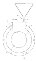
また、図2に示すように、原料供給口21の原料堆積側エッジ部31を曲面とすると、原料堆積側エッジ部31には原料Msが堆積し難くなり、原料Msの堆積の破壊がより容易になる。
For this reason, even when pulverizing a raw material containing oil such as soybean, the raw material Ms does not accumulate and grow, and the raw material M can always be supplied appropriately and a swirling airflow can be generated smoothly. Therefore, it is possible to stably perform crushing by the airflow type pulverizer.
As shown in FIG. 2, if the material deposition
10 ケーシング
11 第一回転翼
12 第二回転翼
13 投入側ケーシング
14 センターケーシング
15 排出側ケーシング
16 シャフト
17 フレーム
18 原料投入部
19 テーパー壁
20 垂壁
21 原料供給口
22 テーパー壁
23 排出口
25、26 ボス
27、28 羽根
29 傾斜面
31 原料堆積側エッジ部
32 原料投入口
35 メッシュ
M 原料
Ms 原料
DESCRIPTION OF
Claims (2)
前記ケーシングの旋回領域の後部に開口する原料供給口の原料堆積側エッジ部に向けて原料を投入するよう構成したことを特徴とする気流式微粉砕機の原料投入部。 The first rotor blade and the second rotor blade are provided in the casing so as to be separated from each other by a predetermined distance, the swirl region is located behind the first rotor blade in the casing, and the pulverization region is between the first rotor blade and the second rotor blade. A tapered wall whose diameter gradually decreases from the pulverization region to the front of the casing, and an inclined surface facing the tapered wall is provided on the second rotor blade to form a classification gap between the tapered wall and the inclined surface. In the airflow type fine pulverizer for finely pulverizing the raw material charged from the raw material charging part by the swirling airflow generated by the rotation of the first rotary blade and the second rotary blade,
Material injection portion of the airflow mill, characterized by being configured so as to inject the raw material toward the source depositing side edge portion of the raw material supply port opening edge at the back of the pivoting region of the casing.
Priority Applications (1)
| Application Number | Priority Date | Filing Date | Title |
|---|---|---|---|
| JP2003405634A JP4372525B2 (en) | 2003-12-04 | 2003-12-04 | Raw material input section of airflow type fine pulverizer |
Applications Claiming Priority (1)
| Application Number | Priority Date | Filing Date | Title |
|---|---|---|---|
| JP2003405634A JP4372525B2 (en) | 2003-12-04 | 2003-12-04 | Raw material input section of airflow type fine pulverizer |
Publications (2)
| Publication Number | Publication Date |
|---|---|
| JP2005161237A true JP2005161237A (en) | 2005-06-23 |
| JP4372525B2 JP4372525B2 (en) | 2009-11-25 |
Family
ID=34728249
Family Applications (1)
| Application Number | Title | Priority Date | Filing Date |
|---|---|---|---|
| JP2003405634A Expired - Fee Related JP4372525B2 (en) | 2003-12-04 | 2003-12-04 | Raw material input section of airflow type fine pulverizer |
Country Status (1)
| Country | Link |
|---|---|
| JP (1) | JP4372525B2 (en) |
Cited By (3)
| Publication number | Priority date | Publication date | Assignee | Title |
|---|---|---|---|---|
| JP2007268457A (en) * | 2006-03-31 | 2007-10-18 | Furukawa Industrial Machinery Systems Co Ltd | Air stream type crusher and operation method for air stream type crusher |
| JP2008012477A (en) * | 2006-07-07 | 2008-01-24 | Furukawa Industrial Machinery Systems Co Ltd | Pneumatic pulverizer and method for recovering residue in its casing |
| CN117258929A (en) * | 2023-11-21 | 2023-12-22 | 威顿水泥集团有限责任公司 | Feed arrangement that cement manufacture used |
Families Citing this family (1)
| Publication number | Priority date | Publication date | Assignee | Title |
|---|---|---|---|---|
| CN103358422B (en) * | 2012-04-10 | 2015-07-22 | 广州爱其科技股份有限公司 | Fine rubber powder processing device |
-
2003
- 2003-12-04 JP JP2003405634A patent/JP4372525B2/en not_active Expired - Fee Related
Cited By (4)
| Publication number | Priority date | Publication date | Assignee | Title |
|---|---|---|---|---|
| JP2007268457A (en) * | 2006-03-31 | 2007-10-18 | Furukawa Industrial Machinery Systems Co Ltd | Air stream type crusher and operation method for air stream type crusher |
| JP2008012477A (en) * | 2006-07-07 | 2008-01-24 | Furukawa Industrial Machinery Systems Co Ltd | Pneumatic pulverizer and method for recovering residue in its casing |
| CN117258929A (en) * | 2023-11-21 | 2023-12-22 | 威顿水泥集团有限责任公司 | Feed arrangement that cement manufacture used |
| CN117258929B (en) * | 2023-11-21 | 2024-01-30 | 威顿水泥集团有限责任公司 | Feed arrangement that cement manufacture used |
Also Published As
| Publication number | Publication date |
|---|---|
| JP4372525B2 (en) | 2009-11-25 |
Similar Documents
| Publication | Publication Date | Title |
|---|---|---|
| JP6091717B2 (en) | Crusher with high processing capacity and method for producing fine paper powder | |
| KR101974679B1 (en) | Horizontal dry mill | |
| CN208407160U (en) | A kind of efficient micronizer | |
| JP4010625B2 (en) | Fine powder production system | |
| JP4372525B2 (en) | Raw material input section of airflow type fine pulverizer | |
| JP2003071307A (en) | Pulverizer | |
| JP6790929B2 (en) | Dry crusher | |
| JP4621884B2 (en) | Airflow type fine grinding machine | |
| JP2009183826A (en) | Fine powder manufacturing apparatus | |
| JP2010201289A (en) | Pulverizer | |
| JP4503338B2 (en) | Raw material charging method and raw material charging apparatus for airflow type fine grinding machine | |
| JP4938411B2 (en) | Airflow crusher | |
| CN205095918U (en) | Vertical hierarchical rubbing crusher of tube -shape | |
| JP4519458B2 (en) | Collection pipe structure of fine powder production equipment | |
| JP4889345B2 (en) | Operation method of airflow crusher | |
| CN204396118U (en) | The disc type airslide disintegrating mill of built-in classifying turbine | |
| CN210474149U (en) | Fluidized bed fluid energy mill | |
| JP4889346B2 (en) | Airflow crusher | |
| JP4783040B2 (en) | Fine powder recovery device for airflow crusher | |
| JP4926524B2 (en) | Airflow crusher rectifier | |
| JP2005334698A (en) | Fine powder recovery apparatus | |
| JP2016041396A (en) | Minute paper powder production method using plurality of kind of crusher | |
| JPH06182242A (en) | High-speed rotary impact type pulverizer | |
| CN202113920U (en) | Crusher with slag discharge hole | |
| JP5075584B2 (en) | Crusher |
Legal Events
| Date | Code | Title | Description |
|---|---|---|---|
| A621 | Written request for application examination |
Effective date: 20060920 Free format text: JAPANESE INTERMEDIATE CODE: A621 |
|
| A977 | Report on retrieval |
Effective date: 20090423 Free format text: JAPANESE INTERMEDIATE CODE: A971007 |
|
| A131 | Notification of reasons for refusal |
Free format text: JAPANESE INTERMEDIATE CODE: A131 Effective date: 20090428 |
|
| A521 | Written amendment |
Free format text: JAPANESE INTERMEDIATE CODE: A523 Effective date: 20090629 |
|
| TRDD | Decision of grant or rejection written | ||
| A01 | Written decision to grant a patent or to grant a registration (utility model) |
Free format text: JAPANESE INTERMEDIATE CODE: A01 Effective date: 20090811 |
|
| A01 | Written decision to grant a patent or to grant a registration (utility model) |
Free format text: JAPANESE INTERMEDIATE CODE: A01 |
|
| A61 | First payment of annual fees (during grant procedure) |
Effective date: 20090902 Free format text: JAPANESE INTERMEDIATE CODE: A61 |
|
| FPAY | Renewal fee payment (prs date is renewal date of database) |
Year of fee payment: 3 Free format text: PAYMENT UNTIL: 20120911 |
|
| R150 | Certificate of patent (=grant) or registration of utility model |
Free format text: JAPANESE INTERMEDIATE CODE: R150 |
|
| FPAY | Renewal fee payment (prs date is renewal date of database) |
Year of fee payment: 3 Free format text: PAYMENT UNTIL: 20120911 |
|
| FPAY | Renewal fee payment (prs date is renewal date of database) |
Free format text: PAYMENT UNTIL: 20130911 Year of fee payment: 4 |
|
| S111 | Request for change of ownership or part of ownership |
Free format text: JAPANESE INTERMEDIATE CODE: R313117 |
|
| S533 | Written request for registration of change of name |
Free format text: JAPANESE INTERMEDIATE CODE: R313533 |
|
| R350 | Written notification of registration of transfer |
Free format text: JAPANESE INTERMEDIATE CODE: R350 |
|
| LAPS | Cancellation because of no payment of annual fees |