JP2005161041A - Game machine - Google Patents
Game machine Download PDFInfo
- Publication number
- JP2005161041A JP2005161041A JP2004330447A JP2004330447A JP2005161041A JP 2005161041 A JP2005161041 A JP 2005161041A JP 2004330447 A JP2004330447 A JP 2004330447A JP 2004330447 A JP2004330447 A JP 2004330447A JP 2005161041 A JP2005161041 A JP 2005161041A
- Authority
- JP
- Japan
- Prior art keywords
- display
- display means
- ball
- displayed
- symbol
- Prior art date
- Legal status (The legal status is an assumption and is not a legal conclusion. Google has not performed a legal analysis and makes no representation as to the accuracy of the status listed.)
- Pending
Links
Images


Abstract
Description
本発明は、複数の表示装置で図柄の変動表示を並行して行う遊技機に関する。 The present invention relates to a gaming machine that performs variable display of symbols in parallel on a plurality of display devices.
従来、複数の始動口と、一方の始動口に球が入賞すると図柄の変動表示を行う表示装置と、他方の始動口に球が入賞すると作動を行う第2種役物とをいずれも遊技盤に備えた遊技機の一例が開示されている(例えば特許文献1を参照)。
また、一の始動口と、当該始動口に球が入賞すると図柄の変動表示を行う表示装置とを遊技盤に備えた遊技機の一例が開示されている(例えば特許文献2を参照)。この遊技機では、表示装置の画面を複数の領域に分けたうえで、各領域においてそれぞれ図柄の変動表示を実現している。
In addition, an example of a gaming machine is disclosed in which a gaming board is provided with one starting port and a display device that displays a change in symbol when a ball wins the starting port (see, for example, Patent Document 2). In this gaming machine, the screen of the display device is divided into a plurality of areas, and a variable display of symbols is realized in each area.
しかし、上述した従来の遊技機は、始動口への入賞に伴って1つの表示装置に図柄変動に関する単一の演出表示がなされるのみであった。そのため、図柄の変動態様を複数設けたとしてもバリエーションに限界があり飽き易いものであった。
また、発射した球が始動口に入賞しなかった場合は、図柄変動の可能性は無く、大当りの可能性が即座に喪失する単純なものであった。そのため、大当りになるまでの通常遊技は単調で退屈であった。
本発明はこのような点に鑑みてなしたものであり、複数の表示装置で図柄の変動表示を並行して行うように構成するとともに、一方の変動表示と他方の変動表示とを関連させたうえで遊技を実現する遊技機を提供することを目的とする。
However, in the conventional gaming machine described above, only a single effect display relating to symbol variation is made on one display device in accordance with winning at the start opening. For this reason, even if a plurality of symbol variation modes are provided, variations are limited and it is easy to get bored.
In addition, when the ball that was launched did not win the starting hole, there was no possibility of symbol variation, and the possibility of a big hit was simply lost. Therefore, the normal game until the big hit was monotonous and boring.
The present invention has been made in view of such a point, and is configured so that a variable display of symbols is performed in parallel on a plurality of display devices, and one variable display and the other variable display are associated with each other. An object is to provide a gaming machine that realizes the above game.
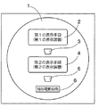
(1)課題を解決するための手段(以下では単に「解決手段」と呼ぶ。)1は、図1に模式的に表すように、遊技盤1の上下方向に配置した第1の始動口3および第2の始動口5(複数の始動口)と、それぞれが図柄の変動表示を行う第1の表示手段2および第2の表示手段4(複数の表示手段)と、大入賞口を覆う特別電動役物6とを備え、前記第1の始動口3また前記第2の始動口5のいずれかに球が入賞すると、当該入賞した始動口に対応する表示手段で図柄の変動表示を行い、前記第1の表示手段2および第2の表示手段4のうちで一方または双方に所定の図柄が表示されて大当りになると、前記特別電動役物6の扉が開放されて前記大入賞口への球の入賞が連続して可能となる特典を付与する構成としたことを要旨とする。
(1) Means for solving the problem (hereinafter simply referred to as “solution means”) 1 is a
第1の表示手段2は、図柄の変動表示を行える装置や画面部位が該当する。具体的には、表示装置または表示器や、表示装置等の画面における一部領域(すなわち表示部)などのうちでいずれかが該当する。このことは第2の表示手段4についても同様である。第1の表示手段2と第2の表示手段4とは別個の装置で実現してもよく、一の装置における別個の表示部で実現してもよい。なお、特別電動役物6の数は任意であり、一つでもよく、複数でもよい。
The 1st display means 2 corresponds to the apparatus and screen part which can carry out the variable display of a symbol. Specifically, any one of a display device or a display device, a partial region (that is, a display unit) on a screen of the display device, or the like corresponds to this. The same applies to the second display means 4. The 1st display means 2 and the 2nd display means 4 may be implement | achieved by a separate apparatus, and may be implement | achieved by the separate display part in one apparatus. In addition, the number of the special
解決手段1によれば、第1の始動口3に球が入賞すると第1の表示手段2で図柄の変動表示を行い、これと並行して第2の始動口5に球が入賞すると第2の表示手段4で図柄の変動表示を行う。すなわち、第1の表示手段2と第2の表示手段4とでは他方の表示手段でどのような表示が行われているかにかかわらず、図柄の変動表示を行う。こうすることで複数の表示手段でそれぞれ図柄の変動表示が行われるが、特に表示内容(例えば変動表示の形態や、背景やキャラクタ等のモチーフなど)を異ならせることで演出に面白味をもたせられるので、見ている遊技者を飽きさせない。なお、二つの表示手段(第1の表示手段2と第2の表示手段4)に限らず、三以上の表示手段を備える場合でも同様の作用効果を得る。
According to the solving means 1, when the ball is won at the first starting
変動表示後に停止表示される図柄に従って大当り/ハズレが確定し、大当りにかかる所定の図柄が停止表示された場合には特典が付与される。具体的には、特別電動役物6の扉が開放されて大入賞口への球の入賞が連続して可能な状態となる。
Bonus / losing is determined according to the symbols that are stopped and displayed after the variable display, and a bonus is given when a predetermined symbol related to the jackpot is stopped and displayed. Specifically, the door of the special
第1の始動口3と第2の始動口5は上下方向に離れて配置されているので、発射させた球が上側の始動口に入賞できなかったとしても、まだ下側の始動口に入賞する可能性が残っている。したがって、発射させた球が下側に配置された始動口を通過するまで遊技者に入賞の期待感を持たせることができる。
Since the
従来のように一の表示装置による図柄の変動表示では、1つの変動表示が終了しない限り、次の変動表示が開始されない。従って、始動口へ立て続けに入賞した場合には変動表示が保留される場合が多かった。そのため、保留数がその上限値に達すると保留が十分消化されるまで長期間球の発射を中断する遊技者が多かった。
これに対して、本願発明では複数の表示手段の全てで変動表示が行われていない限り、変動表示が行われていない表示手段で変動表示を開始させることができるので、遊技者は対応する始動口に入賞させようと球の発射を継続する。したがって、球の発射をやめる時間が短くなるので、結果として遊技機の稼働率を向上させることができる。
In the variable display of symbols by one display device as in the prior art, the next variable display is not started unless one variable display is completed. Therefore, in many cases, the change display is put on hold when winning continuously at the start opening. For this reason, when the number of holds reaches the upper limit, many players interrupt the launch of the ball for a long time until the hold is fully consumed.
On the other hand, in the present invention, unless the variable display is performed on all of the plurality of display means, the variable display can be started by the display means not performing the variable display. Continue to launch the ball to win the mouth. Therefore, since the time for stopping the launch of the ball is shortened, the operating rate of the gaming machine can be improved as a result.
(2)解決手段2は、解決手段1に記載した遊技機であって、第1の始動口3と第2の始動口5とは、入賞の難度が異なるように遊技盤1に配置する構成としたことを要旨とする。
(2) The solution means 2 is the gaming machine described in the solution means 1, and the
解決手段2によれば、上下方向に配置された第1の始動口3と第2の始動口5とでは入賞の難度が異なるので、遊技者は入賞しやすい始動口を狙って球を発射させる遊技が行える。いずれかの始動口に球が入賞すれば図柄の変動表示が行われる点は変わらないが、複数の始動口のうち入賞させやすい始動口を狙って遊技できる点で遊技者に有利である。したがって、所定の難度からなる一の始動口しか備えていない遊技機に比べると、始動口への入賞機会を増やすことができる。
According to the
(3)解決手段3は、解決手段1または2に記載した遊技機であって、第1の表示手段2に所定の図柄が表示されて付与される特典の大きさと、第2の表示手段4に所定の図柄が表示されて付与される特典の大きさとを異ならせる構成としたことを要旨とする。 (3) The solving means 3 is the gaming machine described in the solving means 1 or 2, the size of the privilege given by displaying a predetermined symbol on the first display means 2, and the second display means 4. The gist of the invention is that the size of the privilege given when a predetermined symbol is displayed on the screen is different.
解決手段3によれば、一方の表示手段よりも他方の表示手段のほうが特典の大きさが大きい(または小さい)。複数の表示表示で行われる図柄の変動表示によって大当りになると特典が付与される点では変わらないが、複数の表示手段のうち特典の大きい(または小さい)ほうを狙って遊技できる点で遊技者に有利である。したがって、所定の大きさの特典が付与される遊技機に比べると、技量や入賞難度などを考慮して遊技者が狙う特典の大きさを選択することができる。 According to the solution means 3, the privilege is larger (or smaller) on the other display means than on the other display means. Although it does not change in the point that a privilege is granted when a big hit is made by a variable display of symbols performed in a plurality of display displays, it is possible for a player to play a game aiming at a larger (or smaller) privilege among a plurality of display means It is advantageous. Therefore, compared with a gaming machine to which a privilege of a predetermined size is given, it is possible to select the size of the privilege aimed by the player in consideration of the skill, the winning difficulty level, and the like.
(4)解決手段4は、解決手段1から3のいずれか一項に記載した遊技機であって、第1の表示手段2に所定の図柄が表示されて付与される特典の大きさが第2の表示手段4に所定の図柄が表示されて付与される特典の大きさよりも大きくするとともに、前記第2の表示手段4に所定の図柄が表示される確率が前記第1の表示手段2に所定の図柄が表示される確率よりも高く設定する構成したことを要旨とする。
(4) The solution means 4 is the gaming machine according to any one of the solution means 1 to 3, wherein a predetermined symbol is displayed on the first display means 2 and the size of the privilege given is the first. The probability that the predetermined symbol is displayed on the
解決手段4によれば、第1の表示手段2による特典の大きさは第2の表示手段4による特典より大きいものの、第1の表示手段2に所定の図柄が表示される確率は第2の表示手段4よりも低い。一方、第2の表示手段4では第1の表示手段2とは逆のことが言える。この構成では特典の大きい方を狙って遊技するか、特典の大きさは小さいが出現確率の高い方を狙って遊技するかを遊技者に委ねることができる。よって、遊技者は自らの判断で遊技方法を選択できるので、技量やタイミングなどに応じて遊技方法を選択する楽しみが得られる。 According to the solution means 4, although the magnitude | size of the privilege by the 1st display means 2 is larger than the privilege by the 2nd display means 4, the probability that a predetermined symbol will be displayed on the 1st display means 2 is 2nd. Lower than the display means 4. On the other hand, the second display means 4 can be said to be the reverse of the first display means 2. In this configuration, it is possible to entrust the player to play with the player having a higher privilege, or to play with the player having a smaller bonus but a higher appearance probability. Therefore, since the player can select a game method based on his / her own judgment, he / she can enjoy the selection of the game method according to the skill level and timing.
(5)解決手段5は、解決手段1から4のいずれか一項に記載した遊技機であって、第2の表示手段4にはEL表示装置を用いるとともに第1の表示手段2よりも前側に配置し、前記第2の表示手段4が非表示状態のときは前記第1の表示手段2の表示内容を透過して見えるように構成したことを要旨とする。
(5) The solution means 5 is the gaming machine according to any one of the solution means 1 to 4, wherein an EL display device is used for the second display means 4 and the front side of the
解決手段5によれば、第1の表示手段2と第2の表示手段4とは遊技者から見て前後方向に重なっており、しかも第2の表示手段4にはEL表示装置を用いる。EL表示装置は、その特性によって画面の全部または一部を透過させることができるので、後方側に配置した第1の表示手段2の表示内容を見ることができる。そのため、第1の表示手段2と第2の表示手段4とで重畳して行う表示を見る楽しみを遊技者に与えることができる。
また、第1の表示手段2とEL表示装置とを前後方向に重なるように配置したので、遊技盤1には一の表示装置に必要な領域しか必要としない。そのため、二つ目の表示装置を配置するスペースは球の流下領域や役物装置等に利用することができる。
According to the solution means 5, the first display means 2 and the second display means 4 overlap in the front-rear direction as viewed from the player, and the second display means 4 uses an EL display device. Since the EL display device can transmit all or a part of the screen depending on its characteristics, the display content of the first display means 2 arranged on the rear side can be seen. Therefore, it is possible to give the player a pleasure to see the display superimposed on the first display means 2 and the second display means 4.
Further, since the first display means 2 and the EL display device are arranged so as to overlap in the front-rear direction, the
(6)解決手段6は、解決手段1から5のいずれか一項に記載した遊技機であって、第1の表示手段2で行われる図柄の変動表示で第1の特定表示態様が表示される確率と、第2の表示手段4で行われる図柄の変動表示で第2の特定表示態様が表示される確率とを異ならせる構成としたことを要旨とする。
(6) The solution means 6 is the gaming machine according to any one of the solution means 1 to 5, wherein the first specific display mode is displayed by the variable display of the symbols performed by the first display means 2. The gist is that the probability that the second specific display mode is displayed is different from the probability that the second specific display mode is displayed in the variable display of the symbol performed by the
第1の特定表示態様は、図柄の変動表示の一部(例えば特定のリーチパターン)や、図柄の変動表示とは別個に並行して表示される内容(例えば特定の背景や特定のキャラクタ等)などが該当する。このことは第2の特定表示態様についても同様である。第1の特定表示態様と第2の特定表示態様とは、ほぼ同じ表示態様(例えばアラビア数字と漢数字とを表示する場合について同じ数字を意味すれば同一の表示態様とする)であってもよく、別個の表示態様であってもよい。 The first specific display mode is a part of the symbol variation display (for example, a specific reach pattern) or content displayed in parallel with the symbol variation display (for example, a specific background or a specific character). And so on. The same applies to the second specific display mode. Even if the first specific display mode and the second specific display mode are substantially the same display mode (for example, the same display mode is used if the same number is used for displaying Arabic numerals and Chinese numerals). Alternatively, a separate display mode may be used.
解決手段6によれば、第1の表示手段2で行われる図柄の変動表示について第1の特定表示態様が表示される確率は、第2の表示手段4で行われる図柄の変動表示について第2の特定表示態様が表示される確率よりも高い(または低い)。第1の特定表示態様や第2の特定表示態様として何が行われるのかを遊技者に報知(例えばデモンストレーション表示や遊技説明表示など)すれば、遊技者が興味を持つ特定表示態様もあり得る。複数の表示手段では図柄の変動表示が行われるが、遊技者が興味を持った特定表示態様の出現確率が異なるので、遊技者は表示させたい特定表示態様が行われる表示手段を狙って遊技するようになる。よって、遊技者は自らの判断で楽しみたい特定表示態様を選択できるので、技量やタイミングなどに応じて特定表示態様を選択する楽しみが得られる。 According to the solving means 6, the probability that the first specific display mode is displayed for the variable display of the symbols performed by the first display means 2 is the second probability for the variable display of the symbols performed by the second display means 4. Is higher (or lower) than the probability that the specific display mode is displayed. If the player is notified of what is performed as the first specific display mode or the second specific display mode (for example, a demonstration display or a game explanation display), there may be a specific display mode in which the player is interested. A plurality of display means perform variable display of symbols, but since the appearance probability of a specific display mode in which the player is interested is different, the player plays a game aiming at the display unit in which the specific display mode to be displayed is performed. It becomes like this. Therefore, the player can select a specific display mode that he / she wants to enjoy by his / her own judgment, so that he / she can enjoy the selection of the specific display mode according to the skill level and timing.
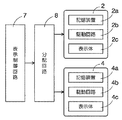
(7)解決手段7は、図2に模式的に表すように、解決手段1から6のいずれか一項に記載した遊技機であって、複数の表示手段に接続され、前記複数の表示手段のうちで表示を行う一以上の表示手段について、表示手段ごとに1フレーム分の画像信号を所定の周期毎に出力する一の表示制御回路7を有し、前記複数の表示手段は、前記一の表示制御回路7から出力される画像信号の中からその表示手段用の画像信号を入力して画像を表示する構成としたことを要旨とする。
(7) The solution means 7 is the gaming machine described in any one of the solution means 1 to 6, as schematically shown in FIG. 2, and is connected to a plurality of display means, and the plurality of display means The
解決手段7によれば、表示制御回路7は所定の周期毎に表示手段ごとに対応して1フレーム分の画像信号を出力し、各表示手段は出力された画像信号を入力して画像を表示する。表示制御回路7と各表示手段との接続方式は、一対一で接続するスター型や、一本の信号線上に複数の表示手段を接続するバス型、円状の信号線上に複数の表示手段を接続するリング型などが該当する。いずれの接続方式にせよ、一の表示制御回路7が複数の表示手段に対して画像信号を伝達することにより画像の表示(すなわち図柄の変動表示等)を実現することができる。したがって、一の表示制御回路7に対して一の表示手段を接続して図柄の変動表示を実現する形態に比べると、一の表示制御回路7で済むので遊技機の製造コストを低く抑えることができる。
According to the solution means 7, the
(8)解決手段8は、解決手段7に記載した遊技機であって、表示制御回路7は、画像信号を出力する表示手段を識別するための識別信号を付加して前記画像信号を出力し、複数の表示手段は、それぞれの表示手段が前記識別信号に基づいて画像信号を入力するか否かを決定し、画像信号を入力すると決定した表示手段が当該画像信号を入力して表示を行う構成としたことを要旨とする。
(8) The solving means 8 is the gaming machine described in the solving means 7, and the
識別信号は、特定の表示手段を作動させるための信号や、表示手段ごとに割り当てた固有の識別情報を含む信号などが該当する。解決手段8によれば、画像信号には識別信号が付加されているので、各表示手段は入力すべき画像信号か否かを確実に判断することができる。したがって、表示手段が誤って画像信号を入力して表示を行うような事態を防止することができる。 The identification signal corresponds to a signal for operating a specific display means, a signal including unique identification information assigned to each display means, or the like. According to the solution means 8, since the identification signal is added to the image signal, each display means can reliably determine whether or not the image signal is to be input. Therefore, it is possible to prevent a situation in which the display means erroneously inputs an image signal and performs display.
(9)解決手段9は、解決手段7に記載した遊技機であって、一の表示制御回路7と複数の表示手段との間に備えられ、前記一の表示制御回路7からの指令信号に従って画像信号を伝達する表示手段を特定し、特定した表示手段に対して画像信号を分配する分配回路8を有する構成としたことを要旨とする。
(9) The solving means 9 is the gaming machine described in the solving means 7, provided between one
解決手段9によれば、一の表示制御回路7は単に画像信号と指令信号とを分配回路8に伝達すればよく、どの画像信号をどの表示手段で表示するかは分配回路8が複数の表示手段に伝達する。よって表示制御回路7は画像信号と指令信号とを出力すればよくなるので、回路を簡単化できる。また、画像信号の分配は分配回路8が行うので、確実に表示させたい表示手段に対して画像信号を伝達することができる。
According to the solution means 9, one
(10)解決手段10は、解決手段7から9のいずれか一項に記載した遊技機であって、複数の表示手段のうちで一以上の表示手段は、表示を行う表示体(図2では表示体2c,4c)と、入力した画像信号を記憶する記憶装置(図2では記憶装置2a,4a)と、当該記憶装置に記憶された画像信号の内容を表示するために前記表示体を駆動する駆動回路(図2では駆動回路2b,4b)とを有し、前記駆動回路は、新たに入力された画像信号が記憶されるまで、現在記憶されている画像信号の内容を表示し続ける構成としたことを要旨とする。
(10) The solving means 10 is the gaming machine described in any one of the solving means 7 to 9, and one or more display means among the plurality of display means are display bodies that perform display (in FIG. 2).
図2の例では、第1の表示手段2は記憶装置2a,駆動回路2b,表示体2cを備え、第2の表示手段4は記憶装置4a,駆動回路4b,表示体4cを備える。解決手段10によれば、複数の表示手段を構成する一以上の表示手段(例えば第1の表示手段2)では、新たに入力された画像信号が記憶されるまで、現在記憶装置(例えば記憶装置2a)に記憶されている画像信号の内容を表示し続ける。言い換えれば、画像信号を入力すると当該画像信号の内容を表示するが、この表示状態は次の画像信号を入力するまで続ける。こうすることにより、表示手段に画像信号を入力する周期が変化しても、表示中のちらつきを防止することができる。
In the example of FIG. 2, the first display means 2 includes a
本発明によれば、第1の表示手段と第2の表示手段とでは他方の表示手段でどのような表示が行われているかにかかわらず、始動口の入賞を契機として図柄の変動表示を行うことができる。特に図柄の変動表示にかかる表示内容を異ならせることで演出に面白味をもたせられるので、見ている遊技者を飽きさせない。 According to the present invention, the first display means and the second display means display a variable display of the symbol at the start opening regardless of the display on the other display means. be able to. In particular, it is possible to make the production interesting by changing the display contents related to the variable display of the symbols, so that the player who is watching is not bored.
本発明を実施するための最良の形態について、図面を参照しながら説明する。 The best mode for carrying out the present invention will be described with reference to the drawings.
〔実施の形態1〕
実施の形態1は遊技機としてのパチンコ機に本発明を適用した例であって、二の表示手段で並行して図柄変動遊技を実現する。当該実施の形態1は、図3〜図8を参照しながら説明する。なお上下左右等の方向を言う場合は、特に明示しない限り、図面に表された内容を基準とする。
[Embodiment 1]
〔パチンコ機の正面側構成例〕
図3はパチンコ機10の正面図である。当該パチンコ機10の遊技盤1(具体的には窓枠14内の遊技領域)には、上下方向に配置した表示役物装置16,22、第1の始動口3、第2の始動口5、ゲート20,54、大入賞口26を覆う特別電動役物6、その他に入賞口や風車,障害釘などを適宜に配置している。なお表示役物装置16,22について、各表示役物装置の具体的な構成や機能等については後述する。
[Example of front side configuration of pachinko machine]
FIG. 3 is a front view of the
第1の始動口3は表示役物装置16の下方に配置し、第2の始動口5は表示役物装置22の下方に配置するので、結果として第1の始動口3の下方に第2の始動口5を配置することになる。これらの第1の始動口3および第2の始動口5のいずれかに球が入賞すると、賞球(賞品球,景品球等とも呼ぶ。)を払い出すように構成されている。
第1の始動口3は、球の入賞を検出する始動口センサ56を有する。また第2の始動口5は、球の入賞を検出する始動口センサ48と、ソレノイド50によって開閉可能な一対の可動片52(いわゆるチューリップ)とを有する。当該一対の可動片52の姿勢に応じて球が入賞し易い状態と入賞し難い状態があるものの、一対の可動片52が閉じて入賞し難い状態であっても球が入賞可能な隙間は確保されている。
Since the
The
遊技盤1の左右には、球の通過を検出するセンサ(図示せず)をそれぞれ備えるゲート20,54が設けられている。これらのセンサのうち少なくとも一方で球の通過を検出すると、第2の始動口5に備えた一対の可動片52を一時的に開放状態(すなわち球が入賞し易い状態)とするように構成されている。
On the left and right sides of the
第2の始動口5の下方には、大入賞口26等を備えた特別電動役物6が設けられている。大入賞口26は、ソレノイド44によって作動する開閉蓋46によって開閉可能に構成されている。特別電動役物6は、開閉蓋46の開放期間(例えば20秒間)内に球が入賞すると所要回数(例えば1回や15回等)を上限としてラウンドを継続可能なVゾーン(特別領域に相当)や、賞球を払い出すに過ぎない一般入賞口(通常領域に相当)等を有する。Vゾーンには、球の入賞を検出するVセンサ58を備える。
Below the
ガラス枠における遊技盤1の下方には、カード類(例えばプリペイドカードやICカード等)の残高範囲内で球貸を指示可能な球貸スイッチ42や、当該カード類の返却を指示可能な返却スイッチ28等を備える。上記ガラス枠の下方に備えた前板30には、賞球の受皿である上皿40や、当該上皿40の内部に設けられて音(音声,音楽,効果音等)を出すスピーカ36等を備える。さらに前板30の下方には、タバコの吸い殻等を入れる灰皿38や、貸球や賞球を含めた球を一時的に貯留する下皿34、球を発射させる際に遊技者が操作するハンドル32等を備える。
Below the
図4は、表示役物装置の拡大正面図である。具体的には、図4(A)には表示役物装置16の拡大図を表し、図4(B)には表示役物装置22の拡大図を表す。
図4(A)に表す表示役物装置16は、第1の表示手段2や、特別図柄表示器68、保留数表示器66、誘導部材64(具体的には左誘導部材64a,右誘導部材64b)などを備える。第1の表示手段2には、例えば液晶表示装置を用いる。第1の表示手段2では球が第1の始動口3に入賞したことを契機に図柄変動遊技が行われ、変動領域62(すなわち左図柄表示部62a、中図柄表示部62bおよび右図柄表示部62cで表示区分された各領域)で図柄の変動表示を行い、停止表示する図柄によって抽選結果を表示する。図柄の変動表示以外では、背景やキャラクタ、遊技説明などを表示し、図柄の変動表示との関係では別個に表示してもよく重畳して表示してもよい。
保留数表示器66は、第1の表示手段2の変動表示中に球が第1の始動口3に入賞した数(言い換えれば図柄の変動表示の残り数)を表示する。例えば左誘導部材64aの場合は矢印D2で示す経路のように、誘導部材64は表示役物装置16の左右横側から入って来た球を第1の始動口3に向けて誘導する。
FIG. 4 is an enlarged front view of the display accessory device. Specifically, FIG. 4A shows an enlarged view of the
The
The number-of-holds
図4(B)に表す表示役物装置22は、第2の表示手段4や、特別図柄表示器82、普通図柄表示器80、保留数表示器78,76、誘導部材74(具体的には左誘導部材74a,右誘導部材74b)などを備える。第2の表示手段4には、例えば液晶表示装置を用いる。第1の表示手段4では球が第1の始動口5に入賞したことを契機に図柄変動遊技が行われ、変動領域72(すなわち左図柄表示部72a、中図柄表示部72bおよび右図柄表示部72cで表示区分された各領域)で図柄の変動表示を行い、停止表示する図柄によって抽選結果を表示する。図柄の変動表示以外に表示する内容は、第1の表示手段2の場合と同様である。
The
保留数表示器76は、第2の表示手段4の変動表示中に球が第2の始動口5に入賞した数(言い換えれば図柄の変動表示の残り数)を表示する。普通図柄表示器80は、例えば緑色と赤色を切換表示可能なLEDを用いて、図柄の変動表示や抽選結果を表示する。普通図柄表示器80における図柄の変動表示は、球がゲート20,54のいずれかを通過したことを契機として開始する。例えば右誘導部材74bの場合は矢印D4で示す経路のように、誘導部材74は表示役物装置22の左右横側から入って来た球を第2の始動口5に向けて誘導する。
The number-of-holds
〔パチンコ機の背面側構成例〕
図5にはパチンコ機10の外観にかかる背面図を表す。パチンコ機10の背面側上部には、球タンク84や、タンクレール86、配電盤88、球払出ユニット90、主基板ボックス92、周辺基板ボックス94、発射モータ96、発射ハンマー98などを備える。
[Example of rear side configuration of pachinko machine]
FIG. 5 shows a rear view of the appearance of the
球タンク84は賞球として払い出す球を一時的に貯留する。タンクレール86は、球タンク84の下方に球が通行可能に接続され、球払出ユニット90に球を供給する。球払出ユニット90はモータや回転体等を有し、後述する払出制御基板92e(図6を参照)からの払出信号に従って回転体を回転させて所要数の球を払い出す。主基板ボックス92および周辺基板ボックス94は、メンテナンスを容易にして不正遊技を防止するため、後述するように複数の基板が各ボックス内に封止されている(図6を参照)。発射モータ96の駆動によって作動する発射ハンマー98は、遊技者がハンドル32を操作する度合い(すなわち回転角)に応じて発射強度が変化するように構成されている。
The
〔基板と装置等との間の接続例〕
次に、パチンコ機10において遊技(図柄変動遊技を含む)を実現するべく構成した基板と装置等との間の接続例について図6を参照しながら説明する。なお図6では、同一の機材はカンマ「,」を用いて連続的に符号を表すが、実際には個別の機材ごとに制御を行う。また、普通図柄表示器80や、当該普通図柄表示器80用の保留数表示器78は図示を省略している。以下の説明では、単に「接続する」という場合には、特に明示しない限り、電気的に接続することを意味する。
[Example of connection between board and equipment]
Next, a connection example between a board configured to realize a game (including a symbol variation game) in the
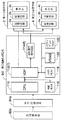
図6において、主基板ボックス92には主制御基板92aや払出制御基板92eなどが封止され、周辺基板ボックス94にはサブ制御基板94a,第1電飾制御基板94e,第2電飾制御基板94f,音制御基板94gなどが封止されている。以下では、各基板の構成や機能などについて簡単に説明する。
In FIG. 6, the
主制御基板92aは、CPU(プロセッサ)92b,ROM92c,RAM92dなどを有する。ROM92cには、パチンコ機10における遊技を司る遊技制御プログラムや、所定のデータ等を格納する。RAM92dには、乱数,保留数カウンタ(特別図柄用保留数,普通図柄用保留数)およびバッファ等のような一時的データを格納する。CPU92bは、上記ROM92cに格納された遊技制御プログラムを実行してパチンコ遊技を実現する。当該遊技制御プログラムには、図柄変動遊技を実現するためのプログラム(例えば後述する始動口処理等)を含む。主制御基板92aは、特別図柄表示器68,82、始動口センサ48,56、ソレノイド44,50などのように遊技進行にかかわる装置を接続する。主制御基板92aは、例えば特別図柄表示器68,82に表示信号を出力して図柄の変動表示を行なったり、始動口センサ48,56やVセンサ58からの信号を入力したり、ソレノイド44,50に作動信号を出力するなどの機能を果たす。その他の構成要素については周知の技術と同様であるので、図示および説明を省略する。
The
払出制御基板92eは球払出ユニット90の動作を制御して賞球の払い出しを実現する。具体的には、主制御基板92aから入賞にかかる情報データが払出制御基板92eに伝達されると、当該入賞に伴って払い出すべき球の数を球払出ユニット90に伝達する。
The
サブ制御基板94aは、CPU94b,ROM94c,RAM94dなどを有する。ROM94cには、サブ制御プログラムや所要のデータ等を格納する。RAM94dには、主制御基板92aから受信したデータ(コマンドデータや識別データを含む)やインターバル時間等の一時的データを格納する。CPU94bはROM94cに格納したサブ制御プログラムを実行し、主制御基板92aから受信したデータに基づいて第1電飾制御基板94e,第2電飾制御基板94f,音制御基板94gを制御する。すなわちコマンドデータの内容を解釈して、第1電飾制御基板94eを通じてランプ群100の表示を制御したり、コマンドデータおよび識別データに基づいて第2電飾制御基板94fを通じて第1の表示手段2や、第2の表示手段4およびランプ群102などの表示を制御したり、音制御基板94gからスピーカ36を通じて音を出す。ランプ群100,102はそれぞれが個別に表示制御する複数個の表示器(例えばLEDや豆電球等)からなり、装飾表示を行うために遊技盤1やガラス枠等に備えた表示体である。その他の構成要素については周知の技術と同様であるので、図示および説明を省略する。
The
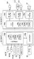
ここで、上述した第2電飾制御基板94fの具体的な構成例を図7に表す。図7に表す第2電飾制御基板94fは、CPU110、VDP(Video Display Processor)112、識別信号発生回路114、制御ROM116、キャラクタROM118、VRAM120、カラーパレットRAM122などを有する。VDP112は表示制御回路7に相当し、識別信号発生回路114は分配回路8に相当する。なお図7では、図6に表したランプ群102の記載を省略している。
Here, the specific structural example of the 2nd electrical decoration control board 94f mentioned above is represented in FIG. 7 has a
CPU110は、主制御基板92aからサブ制御基板94aを経てコマンドデータを入力し、VDP112および識別信号発生回路114を介して第1の表示手段2および第2の表示手段4に表示を行うための制御を司る。VDP112は、CPU110から伝達される信号に基づいて、第1の表示手段2および第2の表示手段4に対して画像信号を出力し、識別信号発生回路114に対して識別データや信号(クロックパルス等のパルス信号を含む)を伝達する。識別信号発生回路114は、VDP112から伝達される識別データに基づいて、第1の表示手段2および第2の表示手段4に対して識別信号を伝達する。この識別信号は、特定の表示手段を作動させるための信号や、表示手段ごとに割り当てた固有の識別情報を含む信号などが該当する。パルス信号などの信号は、1フレーム分の画像信号を送信する周期を刻むためにもちいる。
以下では、これらの要素について具体的な処理内容とともに、当該要素に接続された各要素の機能を簡単に説明する。
The
Below, the function of each element connected to the said element is demonstrated easily with the specific processing content about these elements.
主制御基板92aからサブ制御基板94aを経てコマンドデータを入力したCPU110は、次の手順で表示制御を行う。なお、スケジューラデータは第1の表示手段2および第2の表示手段4に表示する一連の画像のスケジュール(例えば変動表示の停止時期等)を規定している。
The
(手順1)コマンドデータで指定された図柄の変動表示にかかる変動パターンデータ(スケジューラデータ)を制御ROM116から読み出す。
(手順2)制御ROM116から読み出したスケジューラデータを順次解読する。
(手順3)解読した内容に従って、VDP112で取り扱うことが可能な制御信号に変換する。
(手順4)変換した制御信号をVDP112に伝達する。
(Procedure 1) Fluctuation pattern data (scheduler data) related to the symbol variation display designated by the command data is read from the
(Procedure 2) The scheduler data read from the
(Procedure 3) According to the decoded content, the control signal is converted into a control signal that can be handled by the
(Procedure 4) The converted control signal is transmitted to the
ラインバッファ方式で構成されたVDP112には、キャラクタROM118、カラーパレットRAM122、VRAM120が接続されている。キャラクタROM118には、図柄(英数字や図形,キャラクタ等)を表示するための表示用データが格納されている。表示用データは各ドットの色をカラー番号を指定するデータからなり、第1の表示手段2および第2の表示手段4について個別に用意されている。カラーパレットRAM122には、カラー番号ごとにカラーデータが格納されている。VRAM120には、VDP112の画像作成エリアに設定された各領域にどのキャラクタ番号の表示用データを配置するかを指定するデータが格納されている。これらのキャラクタROM118、カラーパレットRAM122およびVRAM120には、第1の表示手段2および第2の表示手段4で並行して図柄の変動表示を実現するのに必要なデータや領域が確保されている。
A
CPU110は第1の表示手段2および第2の表示手段4で並行して表示を行うために、表示手段ごとに1の制御信号を出力するとともに、どの表示手段に対する制御信号なのかを識別するための識別データを出力する。こうして出力された制御信号および識別データを入力したVDP112は、入力した制御信号に基づいて次の手順に従って表示処理を遂行する。この表示処理によって、VDP112はCPU110から1の制御信号を入力するごとに1画像(1フレーム)分の画像信号を出力することになる。
The
(手順1)入力した制御信号に基づいて、VRAM120に格納されているデータの中から、表示にかかるデータを特定する。
(手順2)特定したデータに基づいて、画像作成エリアを構成する各領域に、キャラクタROM118に格納されている表示用データを配置する。
(手順3)第1の表示手段2および第2の表示手段4について個別に配置された表示用データの画像作成エリアから一本ずつ順に走査線を取り出す。
(手順4)取り出した走査線を構成する表示用データ(カラー番号)をカラーパレットRAM122のデータを用いて画像信号に変換する。
(手順5)全ての走査線について上述した手順1〜4を行い、第1の表示手段2および第2の表示手段4に対して画像信号を出力するとともに、出力すべき表示手段を特定するために識別データを識別データを識別信号発生回路114に出力する。識別データを入力した識別信号発生回路114は識別信号を発生させて第1の表示手段2および第2の表示手段4に出力する。
(Procedure 1) Based on the input control signal, the data to be displayed is specified from the data stored in the
(Procedure 2) Based on the specified data, display data stored in the
(Procedure 3) The scanning lines are taken out one by one from the image creation area of the display data individually arranged for the first display means 2 and the second display means 4.
(Procedure 4) Display data (color number) constituting the extracted scanning line is converted into an image signal using data in the
(Procedure 5) To perform the above-described
上述した画像信号および識別信号を入力して表示を行う第1の表示手段2および第2の表示手段4は、例えば次のように構成されている。すなわち第1の表示手段2は記憶装置2a,駆動回路2b,表示体2cなどを有し、第2の表示手段4は記憶装置4a,駆動回路4b,表示体4cなどを有する。このように第1の表示手段2と第2の表示手段4とはほぼ同一に構成されているので、説明を簡単にするために第1の表示手段2の構成要素を代表して説明する。
The first display means 2 and the second display means 4 that display by inputting the image signal and the identification signal described above are configured, for example, as follows. That is, the first display means 2 includes a
記憶装置2aは、VDP112から伝達される画像信号や、識別信号発生回路114から伝達される識別信号などを一時的に記憶する。駆動回路2bは、記憶装置2aに現在記憶されている画像信号の内容に従って表示体2cに印加する駆動電圧を変化させ、表示を実現する。言い換えれば、新たに画像信号や識別信号を入力するまでは、記憶装置2aに記憶された画像信号の内容に従って表示体2cへの表示を行う。第1の表示手段2や第2の表示手段4として液晶表示装置を用いた場合、表示体2cは液晶パネルのことであり、TN(ツイストマネティック)型やSTN型などがある。
The
〔タイムチャートの概要〕
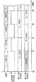
上述した手順および構成によれば、第1の表示手段2および第2の表示手段4では例えば図8に示すようなタイムチャートのように表示が行われる。図8では上から順番に、VDP112が出力する画像信号の内容、識別信号発生回路114から出力する識別信号の内容、第1の表示手段2で表示する内容、第2の表示手段4で表示する内容をそれぞれ表す。この図8では、時間tが経過するにつれて右方向に移行してゆく。
[Overview of time chart]
According to the above-described procedure and configuration, the
図8においてVDP112は、時刻t0から時刻t2まで「A」の画像信号を出力し、時刻t2から時刻t4まで「B」の画像信号を出力し、時刻t4から時刻t6まで「C」の画像信号を出力し、時刻t6から時刻t8まで「D」の画像信号を出力し、時刻t8以降は「E」の画像信号を出力している。識別信号発生回路114は、識別信号としてハイレベル信号(図中の「H」)とローレベル信号(図中の「L」)とを切り換えて第1の表示手段2および第2の表示手段4に伝達し、どの表示手段が表示を行うべきかを指示している。本例では、時刻t0から時刻t2まで、時刻t4から時刻t6まで、時刻t8以降についてローレベル信号を出力し、第1の表示手段2で表示することを指示している。同様に時刻t2から時刻t4まで、時刻t6以降についてハイレベル信号を出力し、第2の表示手段4で表示することを指示している。
In FIG. 8, the
上述した画像信号および識別信号を入力した第1の表示手段2は、時刻t0から時刻t4までは「A」を表示し、時刻t4から時刻t8までは「A」を表示し、時刻t8以降は「E」を表示する。これに対して第2の表示手段4は、時刻t2までは何も表示せず(図中は斜線ハッチを表す)、時刻t2から時刻t6までは「B」を表示し、時刻t6以降は「D」を表示する。 The first display means 2 to which the image signal and the identification signal are input displays “A” from time t0 to time t4, displays “A” from time t4 to time t8, and after time t8. “E” is displayed. On the other hand, the second display means 4 displays nothing until time t2 (represents a hatched hatch in the figure), displays “B” from time t2 to time t6, and “t” after time t6. D ”is displayed.
〔フローチャートの概要〕
パチンコ機10における遊技を実現する手続き例について、図9を参照しながら説明する。当該図9には第1の始動口3および第2の始動口5に対する球の入賞判別を実現する始動口処理の手続きをフローチャートで表す。なお、第1の始動口3への入賞と第2の始動口5への入賞とを個別の手続きで制御する方法もあるが、このフローチャートでは第1の始動口3への入賞と第2の始動口5への入賞とを一の手続きで制御する例である。
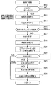
[Outline of the flowchart]
An example of a procedure for realizing a game in the
図9において、まず第1の始動口3および第2の始動口5のいずれかに球が入賞したか否かを判別する〔ステップS10〕。例えば図3,図6に表す始動口センサ56から検出信号を受ければ第1の始動口3に入賞した(YES)と判別し、同じく図3,図6に表す始動口センサ48から検出信号を受ければ第2の始動口5に入賞した(YES)と判別し、当該検出信号を受けていなければ入賞していない(NO)と判別する。もし第1の始動口3や第2の始動口5に球が入賞すると(YES)、各種の乱数を取得したうえでRAM92d等に記憶する〔ステップS12〕。記憶する各種の乱数は、図柄の変動表示を行う表示手段が異なるために始動口ごとに管理し、かつ入賞した球ごとに対応させる。
In FIG. 9, it is first determined whether or not a ball has won a prize in either the
ステップS12で取得する乱数は、カウンタ等を用いたソフトウェア乱数と、発振器等を用いたハードウェア乱数とのいずれか一方または双方を用いる。当該乱数の種類としては、例えば当落判定用乱数RAや、停止図柄用乱数RB、変動表示用乱数RCなどが該当する。当落判定用乱数RAは、大当りか否かを決定するために用いる。停止図柄用乱数RBは、変動表示を停止した際に表示する大当り図柄を特定するために用いる。当該大当り図柄は定の図柄に相当する停止表示用図柄であって、例えば[333]や[777]等のような図柄パターンや、[5]等のような単図柄等が該当する。変動表示用乱数RCは、変動表示の開始から停止までの表示パターン等を特定するために用いる。 As the random number acquired in step S12, one or both of a software random number using a counter or the like and a hardware random number using an oscillator or the like is used. Examples of the random number include a winning determination random number RA, a stop symbol random number RB, and a variable display random number RC. The winning determination random number RA is used to determine whether or not it is a big hit. The stop symbol random number RB is used to specify a jackpot symbol to be displayed when the variable display is stopped. The jackpot symbol is a stop display symbol corresponding to a fixed symbol, and corresponds to a symbol pattern such as [333] or [777] or a single symbol such as [5]. The variable display random number RC is used to specify a display pattern from the start to the stop of the variable display.
各種の乱数を読み終えると、始動口の入賞に伴って所定数(例えば5個や7個等)の球を賞球として払い出すとともに保留数を増やす〔ステップS14〕。ただし、上限値(例えば各始動口ごとに2)が設定されているときは、当該上限値を超えない範囲で増やす。この保留数もまた、上述した各種の乱数と同様に、図柄の変動表示を行う表示手段が異なるために始動口ごとに管理する。増加した結果(保留数)は、第1の始動口3への入賞に対しては保留数表示器66に表示し、第2の始動口5への入賞に対しては保留数表示器76に表示する(図4を参照)。
When various random numbers have been read, a predetermined number (for example, five or seven) of balls is paid out as a winning ball and the number of holdings is increased in accordance with winning at the start opening [Step S14]. However, when an upper limit value (for example, 2 for each starting port) is set, it is increased within a range not exceeding the upper limit value. Similarly to the above-described various random numbers, the number of reservations is also managed for each start port because the display means for displaying the symbol variation is different. The increased result (the number of holdings) is displayed on the holding
ステップS14で保留数を増やすか、あるいはステップS10で第1の始動口3および第2の始動口5の双方に球が入賞していなければ(NO)、変動不能か否か或いは保留数が0以下であるか否かを判別する〔ステップS16〕。すなわち、大当り遊技中であるときや、入賞した始動口に対応する表示手段が変動表示中であるときなどでは変動不能と判別し、そのいずれの状態でもないときは変動可能と判別する。もし保留数が0以下であれば、既に保留にかかる変動表示を全て終えている。
If the number of holds is increased in step S14, or if a ball has not won in both the
もし変動表示が可能な時期であって、かつ保留数が1以上ならば(ステップS16でNO)、大当り判定を行うとともに〔ステップS17〕、保留を消化するべく保留数を減らし〔ステップS18〕、変動表示等を実現するべくコマンドデータおよび識別データを主制御基板92aからサブ制御基板94a等に伝達する〔ステップS20〕。サブ制御基板94aは、コマンドデータで指定された内容に従って第2電飾制御基板94fにデータを送り、識別データで指定された表示手段に対する表示を制御する。
If it is time when the variable display is possible and the number of holdings is 1 or more (NO in step S16), a big hit determination is performed [step S17], and the number of holdings is reduced to digest the holding (step S18). Command data and identification data are transmitted from the
ステップS17の大当り判定は、当落判定用乱数RAに基づいて大当り/ハズレを判定する。具体的には、ステップS12で記憶した当落判定用乱数RAが一以上の当選値のうちいずれか一つと一致するか否かで判定する。ただし、第1の表示手段2および第2の表示手段4では並行して図柄の変動表示を行うので、同時並行して図柄の変動表示を行なっている際に二以上の大当りが発生し得る。この大当り判定では、停止図柄用乱数RBに基づいて変動停止後に表示する図柄を決定したり、変動表示用乱数RCに基づいて変動パターンの選択設定も併せて行う。ステップS18では、上述したステップS14と同様に始動口ごとに管理し、対応する保留数表示器への表示も行う。 In the big hit determination of step S17, the big hit / losing is determined based on the winning determination random number RA. Specifically, the determination is made based on whether or not the winning determination random number RA stored in step S12 matches any one of the one or more winning values. However, since the first display means 2 and the second display means 4 perform the variation display of the symbols in parallel, two or more big hits may occur when the variation display of the symbols is performed in parallel. In this jackpot determination, the symbol to be displayed after the fluctuation is stopped is determined based on the stop symbol random number RB, and the variation pattern is selected and set based on the variation display random number RC. In step S18, it manages for every starting port similarly to step S14 mentioned above, and also displays on a corresponding holding | maintenance number display.
第1の表示手段2で行われる図柄の変動表示でスーパーリーチパターン(第1の特定表示態様に相当)が表示される確率と、第2の表示手段4で行われる図柄の変動表示でプレミアムリーチパターン(第2の特定表示態様に相当)が表示される確率とを異ならせてもよい。ステップS20で伝達する識別データは、図柄の変動表示を行う表示手段を特定するためのデータ(例えばフラグ,英数字等)である。 The probability that a super reach pattern (corresponding to the first specific display mode) is displayed in the variable display of symbols performed by the first display means 2 and the premium reach in the variable display of symbols performed by the second display means 4 The probability that the pattern (corresponding to the second specific display mode) is displayed may be different. The identification data transmitted in step S20 is data (for example, a flag, an alphanumeric character, etc.) for specifying a display means for performing a variable display of symbols.
ステップS20でコマンドデータおよび識別データをサブ制御基板94a等に送信して始めた変動表示を終えるには、所定の変動期間(例えば60秒間等)を要する。よって変動表示中はステップS26,S28の実行を待機する必要がある。そして、図柄の変動表示を終えて停止表示すると、上記ステップS17で判定した結果に基づいて、大当り(すなわち当選)か否かで分岐する〔ステップS22〕。もし、判定結果がハズレであれば(ステップS22でNO)、そのまま始動口処理を終える。
A predetermined variation period (for example, 60 seconds) is required to finish the variation display started by transmitting the command data and the identification data to the
一方、判定結果が大当りであれば(ステップS22でYES)、通常は大当り遊技を実現して賞球を得る機会を遊技者に与えるべく大当り遊技を実現し〔ステップS28〕、始動口処理を終える。大当り遊技の具体的内容は周知の通りであり、例えば大入賞口26を開閉する開閉蓋46を所要期間(例えば30秒間等)開けることで、大入賞口26への球の入賞が連続して可能となる特典を実現する。そして、当該大入賞口26に入賞した球の数に応じて賞球を払い出す。
On the other hand, if the determination result is a big hit (YES in step S22), the big hit game is usually realized so as to give the player an opportunity to obtain the winning ball by realizing the big hit game [step S28], and the start port process is completed. . The specific contents of the jackpot game are well known. For example, by opening the opening / closing
ところがパチンコ機10では、図柄の変動表示を行う表示手段が複数あるので、同時並行して図柄の変動表示を行う場合がある(図3を参照)。よってステップS22で大当りになったとしても、他方の表示手段における図柄の変動表示を終えて既に大当り遊技を実現している場合もある。そこで大当り遊技中であるか否かを判別し〔ステップS24〕、もし大当り遊技中ならば(YES)、そのまま始動口処理を終える。こうして終えた場合における大当りに基づく大当り遊技は、現在行われている大当り遊技を終えた後に実現してもよく、大当り自体を無効としてもよい。
However, in the
通常遊技中であって(ステップS24でNO)、第1の始動口3および第2の始動口5のいずれか一方への入賞に基づいて一の大当りが発生した場合には、通常通りに大当り遊技を実現して賞球を得る機会を遊技者に与えるべく大当り遊技を実現し〔ステップS28〕、始動口処理を終える。
If during normal game (NO in step S24) and one big hit occurs based on winning at either one of the
これに対して、第1の始動口3への入賞に基づく大当りと第2の始動口5への入賞に基づく大当りとが同時に並行して発生する場合がある。例えば先に第1の始動口3に球が入賞した後、第2の始動口5に球が入賞したにもかかわらず、第2の表示手段4での変動表示が第1の表示手段2での変動表示よりも早く終了した場合などが該当する。この場合には大当りを調整し〔ステップS26〕、調整された大当りにかかる大当り遊技を実現する〔ステップS28〕。この調整方法はパチンコ機10の機種や遊技状態,日時等に応じて任意に設定できるが、例えば次に示す調整例が挙げられる。
On the other hand, there may be a case where a big hit based on a winning at the
(調整例1)始動口に球が入賞するタイミング(すなわち時刻)を基準とし、最先に入賞した始動口にかかる乱数(すなわち当落判定用乱数RA)に基づく大当りのみを「大当り」とし、他の始動口にかかる乱数に基づく大当りは無視する。
(調整例2)入賞した複数の始動口にかかる各乱数に基づく大当りのうち、遊技者にとって最も大きな利益が得られる大当りを一つだけ選択し、選択した大当りのみを「大当り」として選択しなかった大当りを無視する。
(調整例3)RAM92d内に大当り待ち行列用の記憶領域を確保し、始動口に球が入賞するタイミングを基準として大当り待ち行列に入賞した始動口や乱数を格納する。先入れ先出し方式に従って大当り待ち行列の先頭にある大当りから順番に「大当り」とする。
(Adjustment example 1) Based on the timing (that is, time) when the ball wins the starting opening as a reference, only the big winning based on the random number (that is, the winning determination random number RA) applied to the starting opening that wins first is set as “big winning”, etc. Ignore the jackpot based on the random number at the starting point.
(Adjustment example 2) Of the big hits based on random numbers applied to a plurality of winning openings, only one big win that gives the greatest profit to the player is selected, and only the selected big hit is not selected as a "big hit" Ignore the big hit.
(Adjustment Example 3) A storage area for the big hit queue is secured in the
ここで、第1の表示手段2と第2の表示手段4とで表示する内容や、大当り図柄、大当り遊技については所要の関係を規定してもよい。例えば、次に示す設定例のうちで一以上の設定例をROM92c等に設定してもよい。
Here, for the contents displayed on the first display means 2 and the second display means 4, the jackpot symbol, and the jackpot game, a required relationship may be defined. For example, among the following setting examples, one or more setting examples may be set in the
(設定例1)第1の表示手段2に大当り図柄が表示されて行われる大当り遊技の内容(例えば16ラウンド)と、第2の表示手段4に大当り図柄が表示されて行われる大当り遊技の内容(例えば10ラウンド)とを異ならせて設定する。この設定では、結果として大当り遊技の大きさが表示手段に依存することになる。
(設定例2)どの表示手段に表示されるかにかかわらず、大当り図柄の種類(具体的には[333]や[555],[777]などの図柄パターンにかかる種類)に応じて、大当り遊技のラウンド数を異ならせて設定する。
(設定例3)第2の表示手段4に表示された大当り図柄に基づいて付与される大当り遊技のラウンド数は、第2の始動口5に備えられた一対の可動片52が開放されたときに入賞したか否かで、第1の表示手段2に表示された大当り図柄に基づいて付与される大当り遊技のラウンド数よりも小さく設定(あるいは大きく設定)する。
(設定例4)第2の表示手段4に大当り図柄が表示される確率は、第1の表示手段2に大当り図柄が表示される確率よりも高く設定する。なお、上記設定例1のように設定したことを条件としてもよい。
(Setting Example 1) Contents of a jackpot game that is played with the jackpot symbol displayed on the first display means 2 (for example, 16 rounds) and contents of a jackpot game that is played with the jackpot symbol displayed on the second display means 4 (For example, 10 rounds) are set differently. With this setting, as a result, the size of the big hit game depends on the display means.
(Setting example 2) Regardless of which display means is displayed, depending on the type of jackpot symbol (specifically, the type related to symbol patterns such as [333], [555], [777], etc.) Set different number of game rounds.
(Setting Example 3) The number of rounds of jackpot game given based on the jackpot symbol displayed on the second display means 4 is determined when the pair of
(Setting Example 4) The probability that a big hit symbol is displayed on the second display means 4 is set higher than the probability that a big hit symbol is displayed on the first display means 2. Note that the setting as in setting example 1 may be used as a condition.
上述した実施の形態1によれば、以下に示す各効果を得ることができる。
(a1)図3を参照すると、遊技盤1の上下方向に離れて第1の始動口3および第2の始動口5(複数の始動口)を配置した。この配置によれば、発射させた球が上側の第1の始動口3に入賞できなかったとしても、まだ下側の第2の始動口5に入賞する可能性が残っている。したがって、発射させた球が下側に配置された第2の始動口5を通過するまで遊技者に入賞の期待感を持たせることができる。
According to the first embodiment described above, the following effects can be obtained.
(A1) Referring to FIG. 3, the
第1の始動口3に球が入賞すると第1の表示手段2で図柄の変動表示を行い、これと並行して第2の始動口5に球が入賞すると第2の表示手段4で図柄の変動表示を行う構成とした。これらの配置や構成において特に表示内容(例えば変動表示の形態や、背景やキャラクタ等のモチーフなど)を異ならせることで演出に面白味をもたせられるので、見ている遊技者を飽きさせない。また、一の表示装置による大当りよりも第1の表示手段2および第2の表示手段4による大当りの機会は増えるので、多くの球を獲得する機会を遊技者に提供することができる。さらに、第1の表示手段2および第2の表示手段4の双方で変動表示が行われていない限り、変動表示が行われていない表示手段で変動表示を開始させることができる。よって一の表示装置のみを備えて同時に一の変動表示しか行われない従来技術に比べると、遊技者は対応する始動口に入賞させようと球の発射を継続する。よって球の発射を中断する時間が短くなるので、結果として遊技機の稼働率が向上する。
When a ball wins the
(a2)図3を参照すると、第1の始動口3と第2の始動口5とは、入賞の難度が異なるように遊技盤1に配置する構成とした。すなわち、第2の始動口5は一対の可動片52が開放されて入賞が容易な状態になるので、このような状態がない第1の始動口3に比べて入賞の難度が低い。言い換えれば、第1の始動口3は第2の始動口5よりも入賞の難度が高い。こうして複数の始動口について入賞の難度を異ならせたので、遊技者は入賞しやすい始動口を狙って球を発射させる遊技が行える。したがって、第1の始動口3と第1の表示手段2の組と、第2の始動口5と第2の表示手段4の組とで、期待度に相違をもたらすことができる。また、所定の難度からなる一の始動口しか備えていない遊技機に比べると、始動口への入賞機会を増やすことができる。
(A2) Referring to FIG. 3, the
(a3)図9のステップS28を参照すると、第1の表示手段2に大当り図柄が表示されて行われる大当り遊技の内容(付与される特典)と、第2の表示手段4に大当り図柄が表示されて行われる大当り遊技の内容(付与される特典)とを異ならせた。したがって、一定の大きさの特典が付与される遊技機に比べると、技量や入賞難度などを考慮して遊技者が狙う特典の大きさを選択することができる。
なお、第1の始動口3は第2の始動口5よりも入賞の難度が高いので、入賞の難度と与えられる特典の大きさとのバランスを調整するために、第1の表示手段2にかかる大当り遊技の内容(例えば16ラウンド)は第2の表示手段4にかかる大当り遊技の内容(例えば10ラウンド)よりも大きくするのが望ましい。
(A3) Referring to step S28 of FIG. 9, the contents of the big hit game (privileged privileges) performed when the big hit symbol is displayed on the first display means 2, and the big hit symbol is displayed on the second display means 4. The content of the jackpot game to be performed (privileges granted) was made different. Therefore, in comparison with a gaming machine to which a certain amount of privilege is given, it is possible to select the size of the privilege aimed by the player in consideration of the skill, the winning difficulty level, and the like.
Since the
(a4)第1の表示手段2に大当り図柄が表示されて付与される大当り遊技のラウンド数が第2の表示手段4に大当り図柄が表示されて付与される大当り遊技のラウンド数よりも大きくするとともに、第2の表示手段4に大当り図柄が表示される確率が第1の表示手段2に大当り図柄が表示される確率よりも高く設定した。この設定によれば、遊技者は大当り遊技にかかるラウンド数の多い方を狙って遊技するか、ラウンド数は少ないが出現確率の高い方を狙って遊技するかを遊技者に委ねることができる。よって、遊技者は自らの判断で遊技方法を選択できるので、技量やタイミングなどに応じて遊技方法を選択する楽しみが得られる。 (A4) The number of rounds of the jackpot game given by displaying the big hit symbol on the first display means 2 is made larger than the number of rounds of the jackpot game given by displaying the big hit symbol on the second display means 4 In addition, the probability that the big hit symbol is displayed on the second display means 4 is set higher than the probability that the big hit symbol is displayed on the first display means 2. According to this setting, the player can leave to the player whether he / she wants to play the game with the larger number of rounds for the big hit game or the player who aims at the player who has a smaller number of rounds but a higher appearance probability. Therefore, since the player can select a game method based on his / her own judgment, he / she can enjoy the selection of the game method according to the skill level and timing.
(a5)第1の表示手段2で行われる図柄の変動表示でスーパーリーチパターンが表示される確率と、第2の表示手段4で行われる図柄の変動表示でプレミアムリーチパターンが表示される確率とを異ならせる構成とした。スーパーリーチパターンやプレミアムリーチパターンの一部を遊技者に報知(例えばデモンストレーション表示や遊技説明表示など)すれば、遊技者が興味を持つリーチパターンもあり得る。よって、遊技者は自らの判断で楽しみたいリーチパターンを選択できるので、技量やタイミングなどに応じてリーチパターンを選択する楽しみが得られる。 (A5) The probability that a super reach pattern is displayed in the variable display of symbols performed by the first display means 2, and the probability that a premium reach pattern is displayed in the variable display of symbols performed by the second display means 4. The configuration is different. If a part of the super reach pattern or premium reach pattern is notified to the player (for example, a demonstration display or a game explanation display), there may be a reach pattern that the player is interested in. Therefore, the player can select a reach pattern to be enjoyed by his / her own judgment, so that he / she can enjoy selecting a reach pattern according to the skill, timing, and the like.
(a6)図7,図8を参照すると、VDP112は、第1の表示手段2および第2の表示手段4に接続され(スター型接続)、これらの複数の表示手段のうちで表示を行う一以上の表示手段について、表示手段ごとに1フレーム分の画像信号を所定の周期毎に出力するように構成した。また、第1の表示手段2および第2の表示手段4は、VDP112から出力される画像信号の中からその表示手段用の画像信号を入力して画像を表示する構成とした。これらの構成によれば、一の表示手段ごとに一のVDP112を接続して図柄の変動表示を実現する従来技術に比べると、複数の表示手段に対して一のVDP112を接続する点でパチンコ機10の製造コストを低く抑えることができる。
(A6) Referring to FIGS. 7 and 8, the
(a7)図7を参照すると、識別信号発生回路114はVDP112と複数の表示手段(第1の表示手段2および第2の表示手段4)との間に備えられ、VDP112からの指令信号に従って画像信号を伝達する表示手段を特定し、特定した表示手段に対して画像信号を分配する機能を備えた。この構成によれば、VDP112は画像信号と指令信号とを出力する機能を持たせるだけで十分であるので、回路を簡単化できる。また、画像信号の分配は識別信号発生回路114が行うので、確実に表示させたい表示手段に対して画像信号を伝達することができる。したがって、表示手段間の誤表示を防止できる。
(A7) Referring to FIG. 7, the identification
(a8)図7を参照すると、第1の表示手段2は、表示体2c、記憶装置2aおよび駆動回路2bを備えた。同様に第2の表示手段4は、表示体4c、記憶装置4aおよび駆動回路4bを備えた。駆動回路2b,4bは、新たに入力された画像信号が記憶されるまで、記憶装置2a,4aに現在記憶されている画像信号の内容を表示し続けるので(図8を参照)、第1の表示手段2および第2の表示手段4に画像信号を入力する周期が変化しても、表示中のちらつきを防止することができる。
(A8) Referring to FIG. 7, the first display means 2 includes a
〔実施の形態2〕
実施の形態2は、上述した実施の形態1と同様にパチンコ機10に本発明を適用し、二の表示部で並行して図柄の変動表示を実現する。当該実施の形態2は、図10を参照しながら説明する。なおパチンコ機10の構成等は実施の形態1と同様であり、説明を簡単にするために実施の形態2では実施の形態1と異なる点について説明する。
[Embodiment 2]
In the second embodiment, the present invention is applied to the
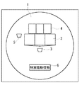
図10には、図1に代わる構成例を表す。まず、一の表示手段9のみを備えた点で実施の形態1と異なる。この表示手段9は例えば液晶表示装置を用いるとともに、第1の表示手段2に相当する第1表示部9aと、第2の表示手段4に相当する第2表示部9bとを同時に表示可能に構成する。第1表示部9aと第2表示部9bとは画面内で表示領域を異ならせて(あるいは表示領域の一部または全部を重畳して)、個別の表示領域内で図柄の変動表示を行う。したがって、複数の表示手段で同時並行して図柄の変動表示を行う点では実施の形態1と同じである。
FIG. 10 shows a configuration example instead of FIG. First, it differs from the first embodiment in that only one display means 9 is provided. The display means 9 uses, for example, a liquid crystal display device, and is configured to be able to simultaneously display a first display section 9a corresponding to the first display means 2 and a
また、第1の始動口3および第2の始動口5は上下方向に配置している点では実施の形態1と同じである。しかし、両始動口は相互間に障害釘を介在させているものの、接近して配置した点で実施の形態1と異なる。このように配置した結果、第1の始動口3に球が入賞する難度は、第2の始動口5に比べて障害釘が少ない分だけ当該第2の始動口5よりも低くなる。
Further, the
従来のパチンコ機は、始動口への入賞に伴って1つの表示装置に図柄変動に関する単一の演出表示がなされるのみであるため、図柄の変動態様を複数設けたとしてもバリエーションに限界があり飽き易いものであった。また、発射した球が始動口に入賞しなかった場合は図柄変動の可能性は無く大当りの可能性が即座に喪失する単純なものであった。そのため、大当りになるまでの通常遊技は単調で退屈であった。
しかし、本形態では上述のように構成したので、始動口により変動表示する表示手段が異なるため、例えば、第1の表示手段2と第2の表示手段4とで交互に連続して図柄変動が停止して大当り/ハズレを確定させたり、両表示手段で図柄の変動時間を異ならせたりして、あるいは、第1の表示手段2と第2の表示手段4の表示モチーフや図柄の変動形態を異ならせて、別個の演出表示をすることが可能である。これにより通常遊技での演出表示が多様化され飽き難い。また、例えば各始動口の上方の釘配置を異ならせ、第1の始動口3と第2の始動口5とでその入賞の難度を異ならせることにより図柄変動の頻度に差を設けることができ、第1の始動口3と第1の表示手段2の組と、第2の始動口5と第2の表示手段4の組とで、期待度に相違をもたらし、それゆえ遊技の多様化を図ることができる。さらに、第1の始動口3に入賞しなかった球が流下し第2の始動口5へ入賞し得るので、遊技者は発射した球が第1の始動口3に入賞しなくとも次の第2の始動口5へと入賞の期待をつないで遊技の興味を持続することができる。
The conventional pachinko machine has only a single effect display related to symbol variation on a single display device as a result of winning a prize at the start opening. Therefore, even if a plurality of symbol variation modes are provided, variations are limited. It was easy to get bored. In addition, if the ball that was launched did not win the starting hole, there was no possibility of symbol variation and the possibility of a big hit was lost immediately. Therefore, the normal game until the big hit was monotonous and boring.
However, since the present embodiment is configured as described above, since the display means for variably displaying differs depending on the starting port, for example, the first display means 2 and the second display means 4 are alternately and continuously changing the symbols. Stop and confirm the big hit / losing, change the time of pattern change between the two display means, or change the display motif and pattern change pattern of the first display means 2 and the second display means 4 It is possible to display different effects by making them different. As a result, the effect display in the normal game is diversified and does not get tired. Further, for example, by changing the arrangement of the nails above each starting port and making the winning difficulty different between the
上述した実施の形態2によれば、以下に示す各効果を得ることができる。
(b1)複数の表示手段を遊技盤に配置した実施の形態1に比べると(図3を参照)、一の表示手段に相当する表示手段9を遊技盤1に配置した。この構成によれば、表示手段の数が少ない分だけパチンコ機10の製造コストを低く抑えることができる。また、球が流下する領域を大きく確保したり、他の役物装置等を設置することができるので、球の動向や役物の動作を見て楽しむ機会を遊技者に与えることができる。
(b2)その他の要件,構成,作用,作動結果等については実施の形態1と同様であるので、実施の形態2は実施の形態1と同様の効果を得ることができる{上述した事項(a1)〜(a8)を参照}。
According to the second embodiment described above, the following effects can be obtained.
(B1) Compared to
(B2) Since other requirements, configurations, operations, operation results, and the like are the same as those in the first embodiment, the second embodiment can obtain the same effects as those in the first embodiment {Matters described above (a1 ) To (a8)}.
〔実施の形態3〕
実施の形態3は、上述した実施の形態1と同様にパチンコ機10に本発明を適用し、複数種類の表示装置で並行して図柄の変動表示を実現する。当該実施の形態3は、図11を参照しながら説明する。なおパチンコ機10の構成等は実施の形態1と同様であり、説明を簡単にするために実施の形態3では実施の形態1と異なる点について説明する。なお前後方向は、遊技者側を前方側とし、遊技機の背面側を後方側とする。
[Embodiment 3]
In the third embodiment, the present invention is applied to the
図1に代わる構成例を図11に表し、図11(A)には正面図を示し、図11(B)には図11(A)のB−B矢視断面図を示す。図11(B)では、下側がパチンコ機10の前面側であり、上側がパチンコ機10の背面側である。また、参考のために図11(B)には透明板G(例えばガラス板や樹脂板等)の位置も表している。
FIG. 11 shows a configuration example instead of FIG. 1, FIG. 11A shows a front view, and FIG. 11B shows a cross-sectional view taken along the line BB in FIG. In FIG. 11B, the lower side is the front side of the
図11(A)および図11(B)において、複数の表示手段(すなわち第1の表示手段2および第2の表示手段4)を備えた点では実施の形態1と同じであるが、第2の表示手段4(具体的には図2に示す表示体4c)を第1の表示手段2よりも前方側に配置した点で異なる。言い換えれば、遊技者から見て第1の表示手段2と第2の表示手段4とが前後方向に重なるように配置する。
11A and 11B, the second embodiment is the same as the first embodiment in that a plurality of display means (that is, the first display means 2 and the second display means 4) are provided. The display means 4 (specifically, the
また、第1の表示手段2と第2の表示手段4とでは、種類の異なる表示装置を用いる点でも実施の形態1と異なる。例えば、第1の表示手段2には機械可動するドラム式の表示装置を用いるが、第2の表示手段4には有機EL(Electro Luminescence)表示装置を用いる。有機EL表示装置が非表示状態のときは、第1の表示手段2の表示内容(一部または全部の内容)を透過して見ることができる。
The
さらに、図11(A)に例示する第1の表示手段2(ドラム式表示装置;第1の表示部に相当する)は、3つの図柄ドラムの周囲を遮蔽箱2eで囲うとともに、第2の表示手段4(有機EL表示装置;第2の表示部に相当する)の表示体の非表示状態では第1の表示手段2をランプやLED等の照明体2dで照らして視認可能とし、第2の表示手段4の表示状態では照明を切って第1の表示手段2を暗視状態とする構成にしてもよい。この構成によれば、第1の表示手段2と第2の表示手段4とで交互に図柄変動が停止して大当り/ハズレを確定させたり、両表示手段で図柄の変動時間を異ならせたり、あるいは第1の表示手段2と第2の表示手段4の表示モチーフや図柄の変動形態を異ならせて、別個の演出表示をすることが可能である。これにより演出表示が多様化され飽き難い。
Furthermore, the first display means 2 (drum type display device; corresponding to the first display unit) illustrated in FIG. 11A surrounds the three design drums with a
従来のパチンコ機は、始動口への入賞に伴って1つの表示装置に図柄変動に関する単一の演出表示がなされるのみであるため、図柄の変動態様を複数設けたとしてもバリエーションに限界があり飽き易いものであった。これを解決するには盤面に表示装置を複数(例えば2つ)配置し、それぞれで図柄を変動表示させて演出表示の多様化を図ることが考えられる。一方、盤面スペースには制限があり、表示装置を複数配置すると他の盤面構成部材の配置や球流下経路に大きな制限が課され、盤面構成の設計の自由度が低下する。
しかし、本形態では上述のように構成したので、始動口により変動表示する表示部が異なるため、例えば、第1の表示手段2と第2の表示手段4とで交互に図柄変動が停止して大当り/ハズレを確定させたり、両表示装置で図柄の変動時間を異ならせたりして、あるいは、第1の表示手段2と第2の表示手段4の表示モチーフや図柄の変動形態を異ならせて、別個の演出表示をすることが可能である。これにより演出表示が多様化され飽き難い。また、第1の表示手段2と第2の表示手段4とを盤面の同じ位置に配置するため盤面のスペースを多く取らない。そのため、他の盤面構成部材の配置や球流下経路に制限を課することなく盤面構成の設計の自由度を高くすることができる。
The conventional pachinko machine has only a single effect display related to symbol variation on a single display device as a result of winning a prize at the start opening. Therefore, even if a plurality of symbol variation modes are provided, variations are limited. It was easy to get bored. In order to solve this, it is conceivable that a plurality of display devices (for example, two) are arranged on the board surface and the symbols are variably displayed to diversify the effect display. On the other hand, there is a limitation on the board space, and if a plurality of display devices are arranged, a great restriction is imposed on the arrangement of other board surface components and the ball flow path, and the degree of freedom in designing the board surface configuration is reduced.
However, in the present embodiment, since it is configured as described above, since the display unit that displays the variation varies depending on the start port, for example, the design variation alternately stops between the
上述した実施の形態3によれば、以下に示す各効果を得ることができる。
(c1)図11を参照すると、複数の表示手段(すなわち第1の表示手段2および第2の表示手段4)とは遊技者から見て前後方向に重なっており、しかも前方側の表示手段(本例では第2の表示手段4)が非表示状態のときは後方側の表示手段(本例では第1の表示手段2)の表示内容について一部または全部を透過して見ることができるように構成した。この構成によれば、遊技盤1には一の表示装置に必要な領域しか必要としないので、二つ目の表示装置を配置するスペースは球の流下領域や役物装置等に利用することができる。前方側の表示手段が表示状態であっても、当該表示手段に表示される内容によっては後方側の表示手段に表示される内容の一部を透過して見ることができる。そのため、複数の表示手段で重畳して行う表示に楽しみを持たせることができる。
(c2)その他の要件,構成,作用,作動結果等については実施の形態1と同様であるので、実施の形態3は実施の形態1と同様の効果を得ることができる{上述した事項(a1)〜(a8)を参照}。
According to
(C1) Referring to FIG. 11, the plurality of display means (that is, the first display means 2 and the second display means 4) overlap in the front-rear direction when viewed from the player, and the front-side display means ( In this example, when the second display means 4) is in the non-display state, the display contents of the rear display means (first display means 2 in this example) can be seen partially or entirely. Configured. According to this configuration, since the
(C2) Since other requirements, configurations, operations, operation results, and the like are the same as those in the first embodiment, the third embodiment can obtain the same effects as those in the first embodiment {Matters described above (a1 ) To (a8)}.
〔実施の形態4〕
実施の形態4は、上述した実施の形態1と同様にパチンコ機10に本発明を適用し、二の表示手段で並行して図柄の変動表示を実現する。当該実施の形態4は、図12を参照しながら説明する。なおパチンコ機10の構成等は実施の形態1と同様であり、説明を簡単にするために実施の形態4では実施の形態1と異なる点について説明する。
[Embodiment 4]
In the fourth embodiment, the present invention is applied to the
図12には、図1に代わる構成例を表す。第1の表示手段2と第2の表示手段4とを備えた点で実施の形態1と同じであるが、次の点で異なる。第1点は、実施の形態1では第1の表示手段2と第2の表示手段4とを上下方向に離して配置したが、上下方向に接近して配置したことである。第2点は、実施の形態1では第1の表示手段2の下方に第2の表示手段4を配置したが、第1の表示手段2の上方に第2の表示手段4を配置したことである。第3点は、実施の形態1では第1の表示手段2と第2の表示手段4とで画面の大きさがほぼ同じであるが、画面の大きさを異ならせたことである。
FIG. 12 shows a configuration example instead of FIG. Although it is the same as
また第1の始動口3と第2の始動口5とについて、第2の始動口5の下方に第1の始動口3を配置した点でも実施の形態1と異なる。さらに、第1の始動口3は第1の表示手段2の下方に配置したが、第2の始動口5は第1の表示手段2や第2の表示手段4の横側に配置した点でも実施の形態1と異なる。したがって、第2の始動口5に球が入賞する難度は、第1の始動口3に球が入賞する難度よりも低くなる。
Further, the
従来のパチンコ機は、始動口への入賞に伴って1つの表示装置の図柄変動を起生させ大当りの抽選表示をするが、発射した球が始動口に入賞しなかった場合は図柄変動の可能性は無くなり大当りの可能性が即座に喪失する単純なものであった。そのため、大当りになるまでの通常遊技中は単調で退屈であった。大当り後は、確変抽選で当りとなり高確率となれば次の大当りも容易に引き当てることができ、さらにその後も確変抽選で高確率を引き当て続けることで大量の賞品球を得ることができる。その一方、最初の大当りを引き当てるまでが困難で、遊技者は多くの球の消費を強いられる場合が多い。すなわち、射幸性が過度に高いものであり、そのため遊技として楽しみにくいという問題があった。
しかし、本形態では上述のように構成したので、大当りでない通常遊技中においても複数の表示手段(すなわち第1の表示手段2および第2の表示手段4)が対応する始動口入賞に伴って変動し、別個に当り抽選の表示を行う。すなわち、抽選に係る表示が複数箇所で行われるため期待感を増加すると共に演出表示の効果も高めるので飽き難い。また、通常遊技中において、高確率に設定される第2の表示手段4で小当りとなり適当数の賞球を得ることができると共に確変抽選で高確率を引き当てれば第1の表示手段2で大当りを引き当てるのが容易になる。そのため、遊技者が通常遊技中に過度に球を消費するのが防止でき射幸性を抑えることができる。その結果、遊技として楽しむことができる。
The conventional pachinko machine causes a symbol variation of one display device to accompany the winning at the start opening and displays a big win lottery display, but if the fired ball does not win the starting opening, the symbol variation is possible It was a simple one that lost its potential and instantly lost the chance of a big hit. Therefore, it was monotonous and tedious during normal games until the big hit. After a big win, if the winning probability is a lottery and the probability is high, the next big hit can be easily awarded, and thereafter, a lot of prize balls can be obtained by continuing to assign a high probability in the probability changing lottery. On the other hand, it is difficult to win the first jackpot, and players are often forced to consume many balls. That is, there is a problem that gambling is excessively high, and therefore it is difficult to enjoy as a game.
However, since the present embodiment is configured as described above, a plurality of display means (that is, the first display means 2 and the second display means 4) vary with the corresponding start opening prize even during a normal game that is not big hit. In addition, the winning lottery is displayed separately. That is, since the display relating to the lottery is performed at a plurality of locations, the expectation is increased and the effect of the effect display is enhanced, so that it is difficult to get tired. Further, during normal games, the second display means 4 set with a high probability can be a small hit and an appropriate number of prize balls can be obtained. It's easy to win big hits. Therefore, it is possible to prevent the player from excessively consuming the ball during the normal game, and to suppress the gambling. As a result, it can be enjoyed as a game.
上述した実施の形態4によれば、以下に示す各効果を得ることができる。
(d1)第1の表示手段2と第2の表示手段4とを遊技盤1のほぼ中央に集中して配置したので、球が流下する領域を大きく確保したり、他の役物装置等を設置できる。したがって、球の動向や役物の動作を見て楽しむ機会を遊技者に与えることができる。
(d2)画面の大きさに応じて、大当り図柄が表示される確率(大当りになる確率)や、特定のリーチパターンになる確率などを異ならせるように構成すれば、遊技者は自らの判断でどの始動口に入賞させるべきかを選択できるので、技量やタイミングなどに応じて遊技方法を選択する楽しみが得られる。
(d3)その他の要件,構成,作用,作動結果等については実施の形態1と同様であるので、実施の形態3は実施の形態1と同様の効果を得ることができる{上述した事項(a1)〜(a8)を参照}。
According to the fourth embodiment described above, the following effects can be obtained.
(D1) Since the first display means 2 and the second display means 4 are concentrated in the center of the
(D2) According to the size of the screen, if the player is configured to vary the probability that a jackpot symbol will be displayed (probability to be a jackpot) or the probability of a specific reach pattern, the player can make his own judgment. Since it is possible to select which starting point to win, the enjoyment of selecting a game method according to the skill or timing can be obtained.
(D3) Since other requirements, configurations, operations, operation results, and the like are the same as those in the first embodiment, the third embodiment can obtain the same effects as those in the first embodiment {Matters described above (a1 ) To (a8)}.
〔他の実施の形態〕
以上、本発明を実施するための最良の形態について実施の形態に従って説明したが、本発明は当該実施の形態に何ら限定されるものではない。言い換えれば、本発明の要旨を逸脱しない範囲内において、種々なる形態で実施することが可能である。例えば、次に示す各形態を実現してもよい。
[Other Embodiments]
As mentioned above, although the best form for implementing this invention was demonstrated according to embodiment, this invention is not limited to the said embodiment at all. In other words, the present invention can be implemented in various forms without departing from the gist of the present invention. For example, the following forms may be realized.
(e1)実施の形態1〜4では、パチンコ機10に本発明を適用した。この形態に代えて、パチンコ機10以外の他の遊技機(例えばアレンジボール機,雀球遊技機等)であって、二の表示手段と二の始動口とを遊技盤1に備えたものにも同様に本発明を適用することができる。当該他の遊技機であっても、二の表示手段では他方の表示手段でどのような表示が行われているかにかかわらず、始動口の入賞を契機として図柄の変動表示を行うことができる。特に図柄の変動表示にかかる表示内容を異ならせることで演出に面白味をもたせられるので、見ている遊技者を飽きさせない。
また、表示手段の数と始動口の数とについては、いずれか一方または双方が三以上を備える形態としてもよい。この形態では、表示手段と始動口との関係を明確にする必要がある。例えば三の表示手段と四の始動口とを備えた場合には、表示手段と始動口とを一対一で対応させると一の始動口が余るので、余った始動口をどの表示手段に対応させるのかを設定しておく必要がある。
(E1) In the first to fourth embodiments, the present invention is applied to the
Moreover, about the number of a display means and the number of start openings, it is good also as a form with which one or both is provided with three or more. In this form, it is necessary to clarify the relationship between the display means and the start port. For example, when three display means and four start openings are provided, one start opening is left when the display means and the start opening correspond to each other one-to-one. It is necessary to set whether or not.
(e2)実施の形態1,4では第1の表示手段2および第2の表示手段4の双方に液晶表示装置を用い、実施の形態2では表示手段9に液晶表示装置を用い、実施の形態3では第1の表示手段2にドラム式の表示装置を用いて第2の表示手段4には有機EL表示装置を用いた。これらの形態で用いた種類の表示装置に代えて、任意の表示装置を用いてもよい。任意の表示装置としては、ドラム式の表示装置、液晶表示装置、有機EL表示装置、無機EL表示装置、CRT、プラズマ表示装置、LED表示装置などが該当する。ただし、表示手段9は第1表示部9aおよび第2表示部9bを表示可能な表示装置に制限され、実施の形態3における第2の表示手段4には画面の一部または全部が透視可能な状態となって第1の表示手段2の表示内容を認識可能な表示装置に制限される。このような表示装置であっても、図柄の変動表示を行うことができ、見ている遊技者を飽きさせない。
(E2) In the first and fourth embodiments, a liquid crystal display device is used for both the first display means 2 and the second display means 4, and in the second embodiment, a liquid crystal display device is used for the display means 9. 3, a drum-type display device is used for the first display means 2, and an organic EL display device is used for the second display means 4. An arbitrary display device may be used instead of the type of display device used in these forms. As an arbitrary display device, a drum type display device, a liquid crystal display device, an organic EL display device, an inorganic EL display device, a CRT, a plasma display device, an LED display device, and the like are applicable. However, the
(e3)実施の形態1〜4では、第1の始動口3に球が入賞した場合の保留と、第2の始動口5に球が入賞した場合の保留とは別個独立して管理する構成とした(図9のステップS14を参照)。この構成に代えて、第1の始動口3に球が入賞した場合の保留と、第2の始動口5に球が入賞した場合の保留とで相互に(または一方的に)移転可能な構成としてもよい。例えば一方の始動口にかかる保留数が上限値に達した後、さらに一方の始動口に球が入賞したときは他方の始動口にかかる保留数を増やすことで、一方の始動口に球が入賞した場合の保留を他方の始動口に球が入賞した場合の保留に移転させる。また、いずれかの表示手段に表示された内容(例えば特定の図柄やキャラクタ等)などの条件に従って、一方の始動口に球が入賞した場合の保留を他方の始動口に球が入賞した場合の保留に移転させてもよい。特に第1の始動口3と第2の始動口5とで入賞の難度が異なる場合には、入賞させやすいほうを狙って球を発射させると、保留の移転によって入賞の難度の高いほうの表示手段で図柄の変動表示を実現させることが可能になる。したがって、遊技者の技量やタイミングなどに応じて遊技方法を選択する楽しみが得られる。
(E3) In the first to fourth embodiments, the hold when the ball is won at the
(e4)実施の形態1〜4では、特別電動役物6および特別電動役物6(すなわちソレノイド44および開閉蓋46)の数を一つとした(図3を参照)。この形態に代えて、特別電動役物6および特別電動役物6の数を複数としもよい。この場合は、個々の特別電動役物6および特別電動役物6と、複数の表示手段との関係を明確にする必要がある。例えば第1の特別電動役物と第2の特別電動役物とを備えた場合には、第1の表示手段2に大当り図柄が表示されて大当りになれば第1の特別電動役物の扉を開放し、第2の表示手段4に大当り図柄が表示されて大当りになれば第2の特別電動役物の扉を開放するように構成する。第1の始動口3と第2の始動口5との関係のように、第1の特別電動役物と第2の特別電動役物とで入賞の難度を異ならせてもよい。さらには遊技中に対応関係を変化させて、第1の表示手段2に大当り図柄が表示されて大当りになれば第2の特別電動役物の扉を開放し、第2の表示手段4に大当り図柄が表示されて大当りになれば第1の特別電動役物の扉を開放するように構成してもよい。こうすれば、遊技者は自らの判断でどの特別電動役物に入賞させるべきか(すなわち遊技者にとって有利な特別電動役物)を選択できるので、技量やタイミングなどに応じて遊技方法を選択する楽しみが得られる。
(E4) In the first to fourth embodiments, the number of the special
(e5)実施の形態1〜4では、VDP112は第1の表示手段2および第2の表示手段4に対して画像信号を出力し、識別信号発生回路114は第1の表示手段2および第2の表示手段4に対して識別信号を出力する構成とした(図7を参照)。この形態に代えて、図13(A)に表すようにVDP112と複数の表示手段(すなわち第1の表示手段2および第2の表示手段4)との間に識別信号発生回路114を介在させる構成としてもよい。VDP112が画像信号を出力する点は変わらないが、識別信号発生回路114はVDP112が出力した画像信号に識別信号を付加して第1の表示手段2および第2の表示手段4に出力する点で異なる。例えば識別信号を画像信号のヘッダーとして付加する例を、図13(B)と図13(C)に示す。
(E5) In the first to fourth embodiments, the
図13(B)の例では、表示を行う一の表示手段にかかる情報をヘッダーに持たせ、当該ヘッダーに続く画像信号は指定された表示手段のみが記憶装置に記憶する。すなわち図中「ヘッダー(2)」は第1の表示手段2で表示すべき情報が含まれているので、このヘッダーに続く画像信号は記憶装置2aに記憶される。また「ヘッダー(4)」は第2の表示手段4で表示すべき情報がヘッダに含まれているので、このヘッダーに続く画像信号は記憶装置4aに記憶される。以下同様にして繰り返すことにより、どの表示手段がどの画像信号を記憶装置に記憶したらよいのかが明確になる。
In the example of FIG. 13B, information related to one display means for display is provided in the header, and only the designated display means stores the image signal following the header in the storage device. That is, since “header (2)” in the figure includes information to be displayed by the first display means 2, the image signal following this header is stored in the
図13(C)の例では、表示を行うべき表示手段にかかる情報をヘッダーに持たせ、当該ヘッダーに続く画像信号は指定された複数の表示手段について交互に記憶装置に記憶する。図中「ヘッダー(2,4)」は第1の表示手段2と第2の表示手段4とで交互に表示すべき情報が含まれているので、このヘッダーに続く画像信号は新たにヘッダーで指定されない限りは記憶装置2aと記憶装置4aとで交互に記憶される。以下同様にして繰り返すことにより、どの表示手段がどの画像信号を記憶装置に記憶したらよいのかが明確になる。
In the example of FIG. 13C, information related to display means to be displayed is provided in a header, and image signals following the header are alternately stored in a storage device for a plurality of designated display means. In the figure, “header (2, 4)” includes information to be alternately displayed by the first display means 2 and the second display means 4, so that the image signal following this header is a new header. Unless otherwise specified, the
一方、第1の表示手段2および第2の表示手段4では、それぞれの表示手段が画像信号に含まれる識別信号に基づいて画像信号を入力するか否かを決定し、画像信号を入力すると決定した表示手段が当該画像信号を入力して表示を行うように構成する必要がある。この構成によれば、画像信号には識別信号が付加されているので、各表示手段は入力すべき画像信号か否かを確実に判断することができる。したがって、表示手段が誤って画像信号を入力して表示を行うような事態を防止することができる。 On the other hand, in the first display means 2 and the second display means 4, each display means determines whether to input an image signal based on an identification signal included in the image signal, and determines to input the image signal. It is necessary for the display means to be configured to input and display the image signal. According to this configuration, since the identification signal is added to the image signal, each display unit can reliably determine whether the image signal is to be input. Therefore, it is possible to prevent a situation in which the display means erroneously inputs an image signal and performs display.
なお図13(A)において、識別信号発生回路114と複数の表示手段(すなわち第1の表示手段2および第2の表示手段4)との間は、実線で図示するように識別信号発生回路114から複数の表示手段に対して同一内容の信号を伝達する形態とした。この形態に代えて、識別信号発生回路114と複数の表示手段との間は、二点鎖線で図示するように識別信号発生回路114に複数の端子を設けて、各端子ごとに一の表示手段を接続し、表示手段で表示すべき信号ごとに分配する構成としてもよい。すなわち、識別信号発生回路114には信号の切換装置としての役割を持たせる。こうすれば、各表示手段は識別信号を解読する必要がなくなるので、回路を簡単化することができる。
In FIG. 13A, the identification
(e6)実施の形態1〜4では、VDP112と第1の表示手段2および第2の表示手段4との間は一対一で接続するスター型とした(図7を参照)。この形態に代えて、VDP112と第1の表示手段2および第2の表示手段4との間は、一本の信号線上に複数の表示手段を接続するバス型、円状の信号線上に複数の表示手段を接続するリング型などとしてもよい。いずれの接続方式にせよ、一の表示制御回路7が複数の表示手段に対して画像信号を伝達して画像の表示(すなわち図柄の変動表示等)を実現することができる。
(E6) In the first to fourth embodiments, the
1 遊技盤
2 第1の表示手段
2a,4a 記憶装置
2b,4b 駆動回路
2c,4c 表示体
2d 照明体
2e 遮蔽箱
3 第1の始動口
4 第2の表示手段
5 第2の始動口
6 特別電動役物
7 表示制御回路
8 分配回路
9 表示手段
9a 第1表示部
9b 第2表示部
10 パチンコ機(遊技機)
12 遊技盤
16,22 表示役物装置
26 大入賞口
44 ソレノイド
46 開閉蓋
48,56 始動口センサ
52 一対の可動片
92 主基板ボックス
92a 主制御基板
92e 払出制御基板
94 周辺基板ボックス
94a サブ制御基板
94e 第1電飾制御基板
94f 第2電飾制御基板
94g 音制御基板
110 CPU
112 VDP(表示制御回路)
114 識別信号発生回路(分配回路)
116 制御ROM
118 キャラクタROM
120 VRAM
122 カラーパレットRAM
DESCRIPTION OF
DESCRIPTION OF
112 VDP (display control circuit)
114 Identification signal generation circuit (distribution circuit)
116 Control ROM
118 Character ROM
120 VRAM
122 Color palette RAM
Claims (1)
前記複数の始動口に球が入賞すると、前記複数の表示装置のうち対応する表示装置で図柄の変動表示を行い、
変動表示が行われた前記表示装置に所定の図柄が表示されて大当りになると、前記特別電動役物の扉が開放されて前記大入賞口への球の入賞が連続して可能となる特典を付与する構成とした遊技機。
Provided with a plurality of starting openings, a plurality of display devices, and a special electric accessory covering the grand prize opening,
When a ball wins at the plurality of starting openings, the display of the symbols is displayed on the corresponding display device among the plurality of display devices,
When a predetermined symbol is displayed on the display device in which variable display is performed and a big hit is made, the special electric accessory door is opened, and a privilege that allows continuous winning of a ball to the big prize opening is provided. A gaming machine configured to grant.
Priority Applications (1)
| Application Number | Priority Date | Filing Date | Title |
|---|---|---|---|
| JP2004330447A JP2005161041A (en) | 2003-11-13 | 2004-11-15 | Game machine |
Applications Claiming Priority (2)
| Application Number | Priority Date | Filing Date | Title |
|---|---|---|---|
| JP2003384287 | 2003-11-13 | ||
| JP2004330447A JP2005161041A (en) | 2003-11-13 | 2004-11-15 | Game machine |
Publications (2)
| Publication Number | Publication Date |
|---|---|
| JP2005161041A true JP2005161041A (en) | 2005-06-23 |
| JP2005161041A5 JP2005161041A5 (en) | 2009-04-30 |
Family
ID=34741757
Family Applications (1)
| Application Number | Title | Priority Date | Filing Date |
|---|---|---|---|
| JP2004330447A Pending JP2005161041A (en) | 2003-11-13 | 2004-11-15 | Game machine |
Country Status (1)
| Country | Link |
|---|---|
| JP (1) | JP2005161041A (en) |
Cited By (20)
| Publication number | Priority date | Publication date | Assignee | Title |
|---|---|---|---|---|
| JP2007000500A (en) * | 2005-06-27 | 2007-01-11 | Daiichi Shokai Co Ltd | Game machine |
| JP2007000497A (en) * | 2005-06-27 | 2007-01-11 | Daiichi Shokai Co Ltd | Game machine |
| JP2007117676A (en) * | 2005-10-31 | 2007-05-17 | Samii Kk | Pinball game machine |
| JP2007252626A (en) * | 2006-03-23 | 2007-10-04 | Heiwa Corp | Game machine |
| JP2008029543A (en) * | 2006-07-27 | 2008-02-14 | Sankyo Kk | Game machine |
| JP2008200406A (en) * | 2007-02-22 | 2008-09-04 | Aruze Corp | Game machine |
| JP2008206804A (en) * | 2007-02-27 | 2008-09-11 | Sankyo Co Ltd | Game machine |
| JP2010022535A (en) * | 2008-07-17 | 2010-02-04 | Sophia Co Ltd | Game machine |
| JP2010119877A (en) * | 2010-03-08 | 2010-06-03 | Sankyo Co Ltd | Game machine |
| JP2010269189A (en) * | 2010-09-08 | 2010-12-02 | Sammy Corp | Pinball game machine |
| JP2011000254A (en) * | 2009-06-18 | 2011-01-06 | Taiyo Elec Co Ltd | Game machine |
| JP2012005897A (en) * | 2011-10-11 | 2012-01-12 | Daiichi Shokai Co Ltd | Game machine |
| JP2013150884A (en) * | 2013-05-13 | 2013-08-08 | Newgin Co Ltd | Game machine |
| JP2014166450A (en) * | 2014-03-28 | 2014-09-11 | Daiichi Shokai Co Ltd | Game machine |
| JP2014184200A (en) * | 2014-04-14 | 2014-10-02 | Daiichi Shokai Co Ltd | Game machine |
| JP2015163369A (en) * | 2015-06-19 | 2015-09-10 | 株式会社大一商会 | Game machine |
| JP2016019869A (en) * | 2015-10-02 | 2016-02-04 | 株式会社大一商会 | Game machine |
| JP2016107023A (en) * | 2014-12-10 | 2016-06-20 | タイヨーエレック株式会社 | Game machine |
| JP2018140252A (en) * | 2018-06-20 | 2018-09-13 | 株式会社三洋物産 | Game machine |
| JP2020005792A (en) * | 2018-07-05 | 2020-01-16 | 株式会社三洋物産 | Game machine |
Citations (4)
| Publication number | Priority date | Publication date | Assignee | Title |
|---|---|---|---|---|
| JP2000014884A (en) * | 1998-06-29 | 2000-01-18 | Ace Denken:Kk | Game machine and game management device |
| JP2001252434A (en) * | 2000-03-14 | 2001-09-18 | Ace Denken:Kk | Game machine |
| JP2003052966A (en) * | 2001-08-10 | 2003-02-25 | Ace Denken:Kk | Game machine |
| JP2003260248A (en) * | 2002-03-12 | 2003-09-16 | Olympia:Kk | Game machine and program and its recording medium |
-
2004
- 2004-11-15 JP JP2004330447A patent/JP2005161041A/en active Pending
Patent Citations (4)
| Publication number | Priority date | Publication date | Assignee | Title |
|---|---|---|---|---|
| JP2000014884A (en) * | 1998-06-29 | 2000-01-18 | Ace Denken:Kk | Game machine and game management device |
| JP2001252434A (en) * | 2000-03-14 | 2001-09-18 | Ace Denken:Kk | Game machine |
| JP2003052966A (en) * | 2001-08-10 | 2003-02-25 | Ace Denken:Kk | Game machine |
| JP2003260248A (en) * | 2002-03-12 | 2003-09-16 | Olympia:Kk | Game machine and program and its recording medium |
Cited By (23)
| Publication number | Priority date | Publication date | Assignee | Title |
|---|---|---|---|---|
| JP2007000497A (en) * | 2005-06-27 | 2007-01-11 | Daiichi Shokai Co Ltd | Game machine |
| JP2007000500A (en) * | 2005-06-27 | 2007-01-11 | Daiichi Shokai Co Ltd | Game machine |
| JP2007117676A (en) * | 2005-10-31 | 2007-05-17 | Samii Kk | Pinball game machine |
| JP2007252626A (en) * | 2006-03-23 | 2007-10-04 | Heiwa Corp | Game machine |
| JP2008029543A (en) * | 2006-07-27 | 2008-02-14 | Sankyo Kk | Game machine |
| JP2008200406A (en) * | 2007-02-22 | 2008-09-04 | Aruze Corp | Game machine |
| JP4485540B2 (en) * | 2007-02-27 | 2010-06-23 | 株式会社三共 | Game machine |
| JP2008206804A (en) * | 2007-02-27 | 2008-09-11 | Sankyo Co Ltd | Game machine |
| JP4542179B2 (en) * | 2008-07-17 | 2010-09-08 | 株式会社ソフイア | Game machine |
| JP2010022535A (en) * | 2008-07-17 | 2010-02-04 | Sophia Co Ltd | Game machine |
| JP2011000254A (en) * | 2009-06-18 | 2011-01-06 | Taiyo Elec Co Ltd | Game machine |
| JP2010119877A (en) * | 2010-03-08 | 2010-06-03 | Sankyo Co Ltd | Game machine |
| JP2010269189A (en) * | 2010-09-08 | 2010-12-02 | Sammy Corp | Pinball game machine |
| JP2012005897A (en) * | 2011-10-11 | 2012-01-12 | Daiichi Shokai Co Ltd | Game machine |
| JP2013150884A (en) * | 2013-05-13 | 2013-08-08 | Newgin Co Ltd | Game machine |
| JP2014166450A (en) * | 2014-03-28 | 2014-09-11 | Daiichi Shokai Co Ltd | Game machine |
| JP2014184200A (en) * | 2014-04-14 | 2014-10-02 | Daiichi Shokai Co Ltd | Game machine |
| JP2016107023A (en) * | 2014-12-10 | 2016-06-20 | タイヨーエレック株式会社 | Game machine |
| JP2015163369A (en) * | 2015-06-19 | 2015-09-10 | 株式会社大一商会 | Game machine |
| JP2016019869A (en) * | 2015-10-02 | 2016-02-04 | 株式会社大一商会 | Game machine |
| JP2018140252A (en) * | 2018-06-20 | 2018-09-13 | 株式会社三洋物産 | Game machine |
| JP2020005792A (en) * | 2018-07-05 | 2020-01-16 | 株式会社三洋物産 | Game machine |
| JP7127392B2 (en) | 2018-07-05 | 2022-08-30 | 株式会社三洋物産 | game machine |
Similar Documents
| Publication | Publication Date | Title |
|---|---|---|
| JP2005161041A (en) | Game machine | |
| JP5290623B2 (en) | Game machine | |
| JP4629720B2 (en) | Game machine | |
| JP4840972B2 (en) | Game machine | |
| JP2017086637A (en) | Game machine | |
| JP5709143B2 (en) | Bullet ball machine | |
| JP5378704B2 (en) | Game machine | |
| JP2017086643A (en) | Game machine | |
| JP6228963B2 (en) | Game machine | |
| JP2005131428A (en) | Pinball machine | |
| JP2017144334A (en) | Game machine | |
| JP2007244621A (en) | Game machine | |
| JP5721170B2 (en) | Bullet ball machine | |
| JP5290624B2 (en) | Game machine | |
| JP5465569B2 (en) | Game machine | |
| JP5999661B2 (en) | Bullet ball machine | |
| JP6288326B2 (en) | Bullet ball machine | |
| JP2017086641A (en) | Game machine | |
| JP2017086639A (en) | Game machine | |
| JP2017086642A (en) | Game machine | |
| JP3685759B2 (en) | Bullet ball machine | |
| JP6090938B2 (en) | Bullet ball machine | |
| JP2022023602A (en) | Game machine | |
| JP2022023601A (en) | Game machine | |
| JP2021027869A (en) | Game machine |
Legal Events
| Date | Code | Title | Description |
|---|---|---|---|
| A621 | Written request for application examination |
Free format text: JAPANESE INTERMEDIATE CODE: A621 Effective date: 20060531 |
|
| RD05 | Notification of revocation of power of attorney |
Free format text: JAPANESE INTERMEDIATE CODE: A7425 Effective date: 20080715 |
|
| A521 | Written amendment |
Free format text: JAPANESE INTERMEDIATE CODE: A523 Effective date: 20090312 |
|
| A977 | Report on retrieval |
Free format text: JAPANESE INTERMEDIATE CODE: A971007 Effective date: 20091228 |
|
| A131 | Notification of reasons for refusal |
Free format text: JAPANESE INTERMEDIATE CODE: A131 Effective date: 20100112 |
|
| A02 | Decision of refusal |
Free format text: JAPANESE INTERMEDIATE CODE: A02 Effective date: 20100518 |