JP2005152103A - Seat reclining device for vehicle - Google Patents
Seat reclining device for vehicle Download PDFInfo
- Publication number
- JP2005152103A JP2005152103A JP2003392343A JP2003392343A JP2005152103A JP 2005152103 A JP2005152103 A JP 2005152103A JP 2003392343 A JP2003392343 A JP 2003392343A JP 2003392343 A JP2003392343 A JP 2003392343A JP 2005152103 A JP2005152103 A JP 2005152103A
- Authority
- JP
- Japan
- Prior art keywords
- lock
- seat back
- reclining
- unlocking
- lever
- Prior art date
- Legal status (The legal status is an assumption and is not a legal conclusion. Google has not performed a legal analysis and makes no representation as to the accuracy of the status listed.)
- Granted
Links
Images


Abstract
Description
この発明は、シートバックを前後に角度調整するリクライニング機能を備える一方で、シートバックをシートクッションに折り重ねるようにして折り畳むことが可能な車両用シートリクライニング装置に関し、特にいわゆるワンボックス車やステーションワゴンタイプなどの自動車のフロントアシスタントシート(一列目シート),セカンドシート(二列目シート)もしくはサードシート(三列目シート)として用いるのに好適な車両用シートリクライニング装置に関する。 The present invention relates to a vehicle seat reclining device that has a reclining function for adjusting the angle of a seat back in the front-rear direction and that can be folded by folding the seat back on a seat cushion. The present invention relates to a vehicle seat reclining device suitable for use as a front assistant seat (first row seat), a second seat (second row seat) or a third seat (third row seat) of an automobile of a type or the like.
上記したようなシートバックをシートクッションに折り畳むことができる車両用シートリクライニング装置としては、例えば下記特許文献1,2に記載されたものがある。
ここで、上記した特許文献1に記載のものは、シートクッションと中間プレートとの連結部に設けたリクライニング機構と、中間プレートとシートバックとの連結部に設けた折り畳み機構とを、中間プレートの中央部に設けた一つの操作レバーで操作する構成としている。
Here, in the above-described
この場合、リクライニング機構および折り畳み機構に対する操作レバーの操作(ロック解除を行う操作)方向が互いに逆であり、折り畳み機構を操作してシートバックをシートクッションに折り畳む状態とする際には、操作レバーによってリクライニング機構を所定角度に操作した後、折り畳み機構を操作する必要がある。 In this case, the operation lever operation (unlocking operation) directions for the reclining mechanism and the folding mechanism are opposite to each other. When the folding mechanism is operated to fold the seat back into the seat cushion, After operating the reclining mechanism at a predetermined angle, it is necessary to operate the folding mechanism.
また、特許文献2に記載のものは、リクライニング機構と折り畳み機構のそれぞれロック解除を、これら各機構相互間に設けた一つのロック解除レバーによって連動して行うようにしている。このロック解除レバーには、リクライニング操作レバーを連結してあり、リクライニング操作レバーを操作すると、まずリクライニング機構のロックが解除され、その後遅れて折り畳み機構のロックが解除される。 In addition, in the device described in Patent Document 2, each of the reclining mechanism and the folding mechanism is unlocked in conjunction with one unlock lever provided between these mechanisms. A reclining operation lever is connected to the unlocking lever, and when the reclining operation lever is operated, the reclining mechanism is first unlocked, and then the folding mechanism is unlocked later.
ところで、上記した特許文献1に記載のものでは、シートバックが後傾した状態、すなわちリクライニング機構が最前傾位置にない状態であっても、折り畳み機構を操作してシートバックを折り畳むことが可能である。この場合、シートバックを水平まで折り畳むことができない。そのため、別にリクライニング機構の操作を必要とし、非常に使い勝手が悪い。
By the way, in the thing of the above-mentioned
そこで、上記した特許文献2に記載のものは、一つのレバーの1回の操作でリクライニング機構と折り畳み機構とを操作する構成としている。 Therefore, the one described in Patent Document 2 described above is configured to operate the reclining mechanism and the folding mechanism by one operation of one lever.
ところで、上記した各特許文献1,2に記載のものは、リクライニング機構と折り畳み機構とを、一つのレバー(前者は操作レバー、後者はロック解除レバー)で操作する構成とするために、このレバーを、リクライニング機構と折り畳み機構との間、すなわち中間プレートの中央部に配置している。
By the way, in each of the above-described
しかし、中間プレートに別途レバーを設けるため、部品点数が増え、コストが高くなる。また、中間プレートは、シートクッションとシートバックとの間に設定するものであって、シートクッションやシートバックによって隠すことができず外部に露出するため、例え樹脂カバーなどでこれらを覆うとしても、カバーが大型化して見栄えが悪化することとなる。 However, since a separate lever is provided on the intermediate plate, the number of parts increases and the cost increases. In addition, the intermediate plate is set between the seat cushion and the seat back, and can not be hidden by the seat cushion or the seat back and exposed to the outside. The cover will become larger and the appearance will deteriorate.
そこで、この発明は、中間プレート周辺の見栄えが悪化することなく、一つのレバーでリクライニング機構と折り畳み機構のそれぞれのロック解除を、容易に行えるようにすることを目的としている。 Accordingly, an object of the present invention is to make it possible to easily unlock each of the reclining mechanism and the folding mechanism with one lever without deteriorating the appearance around the intermediate plate.
前記目的を達成するために、請求項1の発明は、シートクッションの後端とシートバックの下端との間に中間プレートを配置し、前記シートクッションと前記中間プレートとを第1の回転軸を中心として回転可能に連結するとともに、前記シートバックと前記中間プレートとを第2の回転軸によって回動可能に連結し、前記第1の回転軸と前記第2の回転軸とのいずれか一方を中心として前記シートバックを回転させることで、シートバックをシートクッションに対して角度調整する第1のリクライニング機構と、前記第1の回転軸と前記第2の回転軸とのいずれか他方を中心として前記シートバックを回転させることで、シートバックをシートクッションに重ね合わせる第2のリクライニング機構とを備えた車両用シートリクライニング装置において、前記第1のリクライニング機構に前記シートバックの回転を規制する第1のロック機構を設けるとともに、前記第2のリクライニング機構に前記シートバックの回転を規制する第2のロック機構を設け、前記第1,第2の各ロック機構のロック状態をそれぞれ解除する第1,第2の各ロック解除レバーを、前記第1,第2の各回転軸を中心として回転可能に設け、この第1,第2の各ロック解除レバー相互を連結リンクで連結した構成としてある。 In order to achieve the above object, according to the first aspect of the present invention, an intermediate plate is disposed between the rear end of the seat cushion and the lower end of the seat back, and the seat cushion and the intermediate plate are connected to each other with a first rotating shaft. The seatback and the intermediate plate are connected to each other so as to be rotatable about a center, and the second rotation shaft is connected to be rotatable, and one of the first rotation shaft and the second rotation shaft is connected. The first reclining mechanism that adjusts the angle of the seat back with respect to the seat cushion by rotating the seat back as a center, and the other one of the first rotating shaft and the second rotating shaft is the center. A vehicle seat reclining device comprising: a second reclining mechanism that causes the seat back to overlap the seat cushion by rotating the seat back. The first reclining mechanism is provided with a first lock mechanism for restricting rotation of the seat back, and the second reclining mechanism is provided with a second lock mechanism for restricting rotation of the seat back, First and second lock release levers for releasing the locked states of the first and second lock mechanisms are provided so as to be rotatable about the first and second rotation shafts. Each of the second unlocking levers is connected by a connecting link.
上記構成によれば、ロック解除操作の際に、連結リンクで互いに連結している第1,第2の各ロック解除レバーが連動して回転する。 According to the above configuration, during the unlocking operation, the first and second unlocking levers connected to each other by the connecting link rotate in conjunction with each other.
請求項2の発明は、請求項1の発明の構成において、前記第1のリクライニング機構における前記ロック解除レバーの回転中心と、このロック解除レバーの前記連結リンクとの結合部との間の長さを、前記第2のリクライニング機構における前記ロック解除レバーの回転中心と、このロック解除レバーの前記連結リンクとの結合部との間の長さより短くした構成としてある。 According to a second aspect of the present invention, in the configuration of the first aspect of the invention, the length between the center of rotation of the unlocking lever in the first reclining mechanism and the coupling portion of the unlocking lever with the connecting link. Is configured to be shorter than the length between the center of rotation of the unlocking lever in the second reclining mechanism and the connecting portion of the unlocking lever with the connecting link.
上記構成によれば、連結リンクを介して第1,第2の各ロック解除レバーを回転させる際に、ロック解除レバーにおける回転中心とリンクとの連結部との間の長さが短い第1のリクライニング機構におけるロック解除レバーの回転角度が、第2のリクライニング機構におけるロック解除レバーの回転角度より大きくなり、このため第1のリクライニング機構のロック解除が先行してなされ、第1のリクライニング機構によるシートバックのリクライニング操作を先行して行うことが可能となる。 According to the above configuration, when the first and second lock release levers are rotated via the connection link, the length between the rotation center of the lock release lever and the link connecting portion is short. The rotation angle of the lock release lever in the reclining mechanism is larger than the rotation angle of the lock release lever in the second reclining mechanism, so that the unlocking of the first reclining mechanism is preceded, and the seat by the first reclining mechanism It is possible to perform the reclining operation in advance.
請求項3の発明は、請求項1の発明の構成において、前記第1,第2の各ロック機構は、シートバック側またはシートクッション側に設けた回転体の内歯ギアと、前記中間プレート側に回転可能に設けたロックツースの外歯ギアとを、互いに係脱可能に設けるとともに、前記第1,第2の各ロック解除レバーの回転に伴い回転するカムによって前記ロックツースが回転し、このロックツースの外歯ギアと前記回転体の内歯ギアとの噛み合いが外れてロック解除するもので、前記第2のロック機構のロックツースに突起を設けるとともに、前記第2のロック機構の回転体に係合段部を設け、前記第1,第2の各ロック機構におけるロックツースの外歯ギアと回転体の内歯ギアとの噛み合いが外れた状態で、前記突起が前記係合段部に係合し、前記シートバックの前方への回動を規制して、前記第2のロック機構のロック解除を、前記第1のロック機構のロック解除より遅らせる構成としてある。 According to a third aspect of the present invention, in the configuration of the first aspect of the invention, the first and second locking mechanisms include an internal gear of a rotating body provided on a seat back side or a seat cushion side, and the intermediate plate side. The lock tooth external gear provided rotatably is provided so as to be disengageable with each other, and the lock tooth is rotated by a cam that rotates as the first and second lock release levers rotate. The external gear and the internal gear of the rotating body are disengaged to release the lock, and a protrusion is provided on the lock tooth of the second locking mechanism, and an engaging step is provided on the rotating body of the second locking mechanism. And the protrusion engages with the engagement step portion in a state in which the external gear of the lock tooth and the internal gear of the rotating body are disengaged in the first and second lock mechanisms. To regulate the rotation of the front of the seat back, the unlocking of the second lock mechanism, it is constituted to delay than the unlocking of the first locking mechanism.
上記構成によれば、連結リンクを介して第1,第2の各ロック解除レバーを回転させる際に、第1,第2の各ロック機構のロックツースの外歯ギアと回転体の内歯ギアとの噛み合いが外れても、第2のロック機構におけるロックツースの突起が回転体の係合段部に係合し、これによりシートバックの前方への折り畳み方向への回転を規制して、第2のロック機構のロック解除が、第1のロック機構のロック解除より遅れたものとなり、第1のリクライニング機構によるシートバックのリクライニング操作を先行して行うことが可能となる。 According to the above configuration, when the first and second lock release levers are rotated via the connection link, the external tooth gear of the lock tooth of the first and second lock mechanisms and the internal gear of the rotating body Even if the meshing is disengaged, the projection of the lock tooth in the second locking mechanism engages with the engaging step portion of the rotating body, thereby restricting the rotation of the seat back in the forward folding direction, The unlocking of the locking mechanism is delayed from the unlocking of the first locking mechanism, and the seat back reclining operation by the first reclining mechanism can be performed in advance.
請求項4の発明は、請求項1ないし3のいずれかの発明の構成において、前記第1,第2の各ロック解除レバーは、互いに同一方向への回転によってロック解除するもので、この各ロック解除レバーの回転中心から一方へ突出した端部相互を前記連結リンクで連結し、前記第1のリクライニング機構における前記ロック解除レバーの回転中心から他方へ突出する端部に、このロック解除レバーを解除方向に回転させる操作レバーを連結し、この操作レバーの解除方向への回転によってこのロック解除レバーが前記連結リンクに対して移動可能となるよう連結した構成としてある。 According to a fourth aspect of the present invention, in the configuration of any one of the first to third aspects, the first and second lock release levers are unlocked by rotation in the same direction. The ends protruding to one side from the rotation center of the release lever are connected by the connecting link, and the lock release lever is released to the end protruding from the rotation center of the lock release lever to the other side in the first reclining mechanism. An operation lever that is rotated in the direction is connected, and the lock release lever is connected to the connection link by rotation in the release direction of the operation lever.
上記構成によれば、操作レバーを操作することで、第1のリクライニング機構におけるロック解除レバーの連結リンクへの連結部側の端部が連結リンクに対して移動し、第1のリクライニング機構におけるロック機構のみのロック解除がなされる。 According to the above configuration, by operating the operating lever, the end of the unlocking lever in the first reclining mechanism on the connecting part side to the connecting link moves with respect to the connecting link, and the lock in the first reclining mechanism Only the mechanism is unlocked.
請求項5の発明は、前記第1のリクライニング機構における前記ロック解除レバーに連結ピンを設け、この連結ピンが移動可能となる長孔を前記連結リンクに設けた構成としてある。 According to a fifth aspect of the present invention, a connection pin is provided in the lock release lever in the first reclining mechanism, and a long hole through which the connection pin can move is provided in the connection link.
上記構成によれば、操作レバーを操作することで、第1のリクライニング機構におけるロック解除レバーの連結ピンが連結リンクの長孔に対して移動し、第1のリクライニング機構におけるロック機構のみのロック解除がなされる。 According to the above configuration, by operating the operation lever, the connecting pin of the unlocking lever in the first reclining mechanism moves with respect to the long hole of the connecting link, and only the locking mechanism in the first reclining mechanism is unlocked. Is made.
請求項1の発明によれば、第1,第2の各ロック解除レバー相互間には、これら相互を連結する連結リンクを設けるだけであり、中間プレートにはロック解除操作レバーなどの操作レバーを設ける必要がないので、構造の簡素化が図れ、中間プレートを例えば樹脂カバーなどで覆ったとしても、樹脂カバーは小さくでき、見栄えの悪化を防止することができる。 According to the first aspect of the present invention, it is only necessary to provide a connection link for connecting the first and second lock release levers to each other, and an operation lever such as a lock release operation lever is provided on the intermediate plate. Since it is not necessary to provide it, the structure can be simplified, and even if the intermediate plate is covered with, for example, a resin cover, the resin cover can be made small, and deterioration of appearance can be prevented.
請求項2の発明によれば、ロック解除操作の際に、第1のリクライニング機構のロック解除レバーを、第2のリクライニング機構のロック解除レバーに比べて大きく回転させることができるので、第1のリクライニング機構におけるロック機構のロック解除を、第2のリクライニング機構のロック機構のロック解除より先にでき、シートバックの角度調整を行った後に、シートバックの折り畳み作業を行うことができる。 According to the second aspect of the present invention, the unlocking lever of the first reclining mechanism can be rotated more greatly than the unlocking lever of the second reclining mechanism during the unlocking operation. The unlocking of the locking mechanism in the reclining mechanism can be performed prior to the unlocking of the locking mechanism of the second reclining mechanism, and the seat back can be folded after adjusting the angle of the seat back.
請求項3の発明によれば、ロック解除時に、第1のリクライニング機構におけるロック機構のロックツースの外歯ギアと回転体の内歯ギアとの噛み合いが外れてロックが解除された状態でも、第2のリクライニング機構におけるロック機構では、外歯ギアと内歯ギアとの噛み合いが外れるものの、突起が係合段部に当接することで、ロック状態を保持できるので、第1のリクライニング機構におけるロック機構のロック解除を、第2のリクライニング機構におけるロック機構のロック解除より先にでき、シートバックの角度調整を行った後に、シートバックの折り畳み作業を行うことができる。
According to the invention of
請求項4の発明によれば、操作レバーを操作して第1のリクライニング機構におけるロック解除レバーを解除方向に回転させても、このロック解除レバーの連結リンクに対する連結部は、連結リンクに対して移動するので、第2のリクライニング機構のロック解除レバーの回転を防止することができ、第1のリクライニング機構のみの操作を行うことができる。 According to the invention of claim 4, even if the operation lever is operated to rotate the lock release lever in the first reclining mechanism in the release direction, the connection portion of the lock release lever with respect to the connection link is Since it moves, rotation of the unlocking lever of the second reclining mechanism can be prevented, and only the first reclining mechanism can be operated.
請求項5の発明によれば、操作レバーを操作して第1のリクライニング機構におけるロック解除レバーを解除方向に回転させる際に、このロック解除レバーの連結ピンが連結リンクの長孔内を移動するので、第1のリクライニング機構のみの操作を確実に行うことができる。
According to the invention of
以下、この発明の実施の形態を図面に基づき説明する。 Embodiments of the present invention will be described below with reference to the drawings.
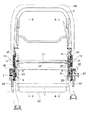
図1は、この発明の第1の実施形態に係わる車両用シートリクライニング装置を示す正面断面図、図2は、図1のA−A矢視断面図、図3は、図1のB−B矢視断面図である。この車両用シートリクライニング装置は、シートクッションSCのフレーム(クッションフレーム)1とシートバックSBのフレーム(バックフレーム)3との間に中間プレート5を配置している。
1 is a front sectional view showing a vehicle seat reclining device according to a first embodiment of the present invention, FIG. 2 is a sectional view taken along line AA in FIG. 1, and FIG. 3 is a sectional view taken along line BB in FIG. It is arrow sectional drawing. In this vehicle seat reclining device, an
上記した中間プレート5の一端(下端)とクッションフレーム1の後端とを、第1の回転軸7を中心として回転可能に連結して第1のリクライニング機構9を構成するとともに、中間プレート5の他端(上端)とバックフレーム3の下端とを第2の回動軸11を中心として回転可能に連結して第2のリクライニング機構13を構成している。
One end (lower end) of the
これら各リクライニング機構9,13は、図2,図3に示すように車両用シートの左右両側にそれぞれ設定してあり、左右の第1のリクライニング機構9,9同士は連結ワイヤ15で互いに連結して連動するとともに、左右の第2のリクライニング機構13,13同士は連結ロッド17で互いに連結して連動する。
These reclining
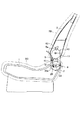
そして、第1のリクライニング機構9により、シートバックSBを中間プレート5とともに第1の回転軸7を中心として回転させることで、シートバックSBをシートクッションSCに対して角度調整する。また、中間プレート5を図2,図3のように起立させた(最前傾させた)状態で、第2のリクライニング機構13により、シートバックSBを第2の回転軸11を中心として回転させることで、シートバックSBをシートクッションSCに折り重ねるようにして折り畳むことが可能となる。すなわち、第2のリクライニング機構13は折り畳み機構を構成している。
Then, the
上記した第1,第2の各リクライニング機構9,13には、図1の左右の各リクライニング機構9,13周辺の拡大図である図4,図5に示す、後述する第1,第2の各ロック機構19,21をそれぞれ設けてあり、一方側のロック機構19,21のロックを解除するために、第1,第2の各回転軸7,11には、第1,第2の各ロック解除レバー23,25を連結固定してある。
The above-described first and
図2に示すように、第1のロック解除レバー23は、第1の回転軸7に固定する中心部から互いに離れる方向に突出する一対の端部23a,23bを備える一方、第2のロック解除レバー25は、第2の回転軸11に固定する中心部から一方向に突出する端部25aを備える。
As shown in FIG. 2, the first unlocking
また、図2に示す第1の回転軸7は、図1に示すように、外方に突出しており、この突出端部に操作ノブ27を設けている。操作ノブ27を掴み第1の回転軸7を介して第1のロック解除レバー23を、図2中で反時計回り方向に回転させることで、第1のロック機構19のロックを解除する。
Moreover, the 1st
図2に示すように、第1のロック解除レバー23の前記した一方の端部23aには連結ピン29を設け、この連結ピン29に連結具31を介して前記した連結ワイヤ15の一端を連結してある。この連結ワイヤ15の他端は、図3に示す反対側の第1のロック解除レバー23の一方の端部23aに設けた連結ピン29に、連結具31を介して連結している。
As shown in FIG. 2, a connecting
したがって、前記した操作ノブ27を図2中で反時計回り方向に回転させることで、左右両側の第1のロック機構19,19のロックをそれぞれ解除することになり、このロック解除状態で、シートバックSBを中間プレート5とともに、第1の回転軸7を中心として回転させることで、シーバック3の角度調整が可能となる。このとき、第2のロック機構21は、ロック状態であり、シートバックSBと中間プレート5との相対回転は発生せず、図2,図3に示した状態を保持している。
Accordingly, by rotating the
図2に示してある左側の第1,第2の各リクライニング機構9,13においては、第1のロック解除レバー23の他方の端部23bに設けた連結ピン33と、第2のロック解除レバー25の端部25aに設けた連結ピン35とを、連結リンク37によって互いに連結している。
In each of the first and
ここで、連結リンク37の第1のロック解除レバー23側の連結ピン33との連結部には長孔37aを形成してあり、この長孔37a内を連結ピン33が移動可能となっている。これは、前記図1に示してある操作ノブ27の操作による第1のロック解除レバー23の図2中で反時計回り方向への回転時に、連結ピン33が長孔37aを移動して、第1のロック機構19のみのロック解除を可能とするためである。
Here, a
上記した第2のリクライニング機構13側の連結ピン35には、連結具39を介してロック解除ケーブル41の一端を連結し、ロック解除ケーブル41の他端は、シートバックSBの上方に引き出し、シートバックSBの背面あるいは上端に設定する図示しないロック解除操作レバーに連結する。
One end of the
すなわち、上記した図示しないロック解除操作レバーを引っ張ることで、連結リンク37を介して第1,第2の各ロック解除レバー23,25が、図2中で反時計回り方向に回転し、これにより第1,第2の各ロック機構19,21双方のロックを解除し、この状態でシートバックSBを折り畳む操作を行う。
That is, by pulling the unlocking operation lever (not shown), the first and second unlocking
このとき、第1のロック機構19のロック解除を先に行い、その後第2のロック機構21のロック解除を行わせる必要がある。これは、第1のリクライニング機構9により中間プレート5を起立状態とした上で、シートバックSBを前方へ折り畳むためである。
At this time, the
そのために、図6(b)の模式図に示すように、第1の回転軸7と、第1のロック解除レバー23と連結リンク37との連結部である連結ピン33との間の長さAを、第2の回転軸11と、第2のロック解除レバー25と連結リンク37との連結部である連結ピン35との間の長さBより短くしている。
Therefore, as shown in the schematic diagram of FIG. 6B, the length between the first
これにより、図示しないロック解除操作レバーを掴んでロック解除ケーブル41を矢印Cで示す方向に引っ張ると、連結リンク37を介して第1,第2の各ロック解除レバー23,25がともに回転するが、第1のロック解除レバー23の方が第2のロック解除レバー25より回転角度が大きくなるので、第1のロック機構19が先にロック解除され、その後に第2のロック機構21のロック解除がなされる。
As a result, when the unlocking operation lever (not shown) is grasped and the unlocking
なお、図6(a),(b)は、ロック解除前の初期状態を示し、(a)は図3に対応し、(b)は図2に対応している。 6A and 6B show an initial state before unlocking, FIG. 6A corresponds to FIG. 3, and FIG. 6B corresponds to FIG.
以後図7〜図9は、図6の初期状態からロック解除操作レバーを操作したときの動作を順に示しており、いずれの図においても、(a)は図3に対応し、(b)は図2に対応している。 Hereinafter, FIGS. 7 to 9 sequentially show the operations when the unlocking operation lever is operated from the initial state of FIG. 6. In each figure, (a) corresponds to FIG. 3, and (b) This corresponds to FIG.
図6の初期状態から、図示しないロック解除操作レバーを操作してロック解除ケーブル41を矢印Cの方向に引っ張ると、まず第1のロック機構19のロックが解除されるのは前述したとおりであり、このとき第1,第2の各ロック解除レバー23,25が、図6(b)中で反時計回りに回転して図7(b)の状態となる。
When the unlocking lever (not shown) is operated and the unlocking
これに伴い反対側の図6(a)における第1のロック解除レバー23も、図6(b)における第1のロック解除レバー23とほぼ同じ角度だけ図6(a)中で時計回り方向に回転するとともに、図6(a)における第2の回転軸11も図6(b)の第2のロック解除レバー25とほぼ同じ角度だけ図6(a)中で時計回り方向に回転する。
Accordingly, the first unlocking
これにより、上記図7の状態で、左右の第1のロック機構19のロック解除がなされ、この状態でシートバックSBを、中間プレート5とともに第1の回転軸7を中心として角度調整可能となる。
Accordingly, in the state shown in FIG. 7, the left and right
なお、中間プレート5とシートクッションSCのフレーム1との間には、シートバックSBを前傾方向に付勢するリターンスプリング42が設けられているので、左右の第1のロック機構19がロック解除されると、中間プレート5は最前傾位置まで回動する。
A
図7の第1のロック機構19のロック解除した状態から、さらにロック解除操作レバーを操作してロック解除ケーブル41を同方向に引っ張ると、第1,第2の各ロック解除レバー23,25が、図7(b)中で反時計回りに回転して図8(b)の状態となる。
When the unlocking operation lever is further operated and the unlocking
これに伴い反対側の図7(a)における第1のロック解除レバー23も、図7(b)における第1のロック解除レバー23とほぼ同じ角度だけ図7(a)中で時計回り方向に回転するとともに、図7(a)における第2の回転軸11も、図7(b)の第2のロック解除レバー25とほぼ同じ角度だけ図7(a)中で時計回り方向に回転する。
Accordingly, the first unlocking
これにより、上記図8の状態で、左右の第2のロック機構21のロック解除がなされ、この状態でシートバックSBを、前方に押し倒してシートクッションSC上に折り畳むことができる。なお、シートバックSBをシートクッションSC上に折り畳む際には、第1のロック機構19のロックが解除されているので、前記図7の状態で、中間プレート5は図2に示すように最前傾位置である起立状態に移動している。
Thus, in the state shown in FIG. 8, the left and right
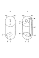
次に、第1,第2の各ロック機構19,21について説明する。この各ロック機構19,21は、基本的な構造は同一であり、ここでは図4に示す第2のリクライニング機構13における第2のロック機構21を用いて説明する。図9は、この第2のロック機構21における主な部品のみを示した分解斜視図である。
Next, the first and
図4,図9に示すように、第2の回転軸11にはカム43を固定し、このカム43は、中間プレート5の図4中で右側に固定してある機枠45と、シートバックSB側のアームプレート47に固定してある回転体としての蓋体49との間に収容してある。機枠45と蓋体49の外周側は、図4に示すホルダ51で覆い、これにより機枠45および蓋体49は、軸方向に分離することなく相互に回転可能に支持された状態となる。
As shown in FIGS. 4 and 9, a
なお、上記した蓋体49は、第1のリクライニング機構9における第1のロック機構19側では、シートクッションSC側のベースプレート53に固定している。
The
上記したカム43の外周側には、一対のロックツース55を、機枠45に設けた軸部57を中心として回転可能に設けてある。ロックツース55の外周部には外歯ギア55aを形成する一方、蓋体49の内周部には、外歯ギア55aが噛合可能な内歯ギア49aを形成してある。
On the outer peripheral side of the
そして、上記したカム43の回転により、ロックツース55が外周側へ押し付けられて軸部57を中心として回転し、その外歯ギア55aが内歯ギア49aに噛み合うことで、蓋体49が機枠45に対して回転が規制される。すなわち、蓋体49を固定してあるアームプレート47側のシートバックSBが、機枠45を固定してある中間プレート5に対して回転が規制されたロック状態となる。
Then, by the rotation of the
また、各ロックツース55の両側には、カム43を回転時にガイドするガイド突起59,61を機枠45から突出して設けてある。
Further, on both sides of each
また、第1のリクライニング機構9においては、一方のロックツース55に対応するガイド突起59と、他方のロックツース55に対応するガイド突起61との間に、図示しないリターンスプリングを設置してある。このリターンスプリングは、カム43を、外歯ギア55aが内歯ギア49aに噛み合う方向に付勢するものであり、第2のリクライニング機構13にも同様に設けてある。
In the
したがって、第1のリクライニング機構9における第1のロック機構19のロックを解除する際には、第1のロック解除レバー23の回転とともにカム43が上記したリターンスプリングの弾性力に抗して図9中で矢印D方向に回転し、このカム43に押されてロックツース55も回転して外歯ギア55aが内歯ギア49aから離れ、両ギア55a,49a相互の噛み合いが解除される。
Therefore, when the
さらに、第2のリクライニング機構13における第2のロック機構21には、図9に示すように、ロックツース55の外歯ギア55a近傍の側面に、蓋体49側に向けて突出する突起55bを設けている。一方、蓋体49の内歯ギア49aより中心側の内側面には、係合段部49bを設け、この係合段部49bを境にして円周方向の一方側にて中心側に位置する突起乗り上げ面49cを設けてある。
Further, as shown in FIG. 9, the
この突起乗り上げ面49cに、ロック解除時にロックツース55の突起55bが乗り上げることで、所定角度範囲においてロックツース55の外歯ギア55aと蓋体49の内歯ギア49aとが噛み合わないようにしている。ロックツース55の突起55bが突起乗り上げ面49cに乗り上げる状態とは、シートバックSBを図2における状態より前方に倒した状態であり、この状態で第2のロック機構21のロックが解除された状態となる。
The
上記ロック解除された状態(シートバックSBを中間プレート5に対し図2の状態より前方へ倒した状態)、すなわち突起55bが突起乗り上げ面49cに乗り上げた状態から、シートバックSBを後方へ倒すと、蓋体49がシートバックSBとともに回転するので、突起55bは突起乗り上げ面49cを摺接移動した後、係合段部49bに落ち込み、この状態でシートバックSBは前方への回転が規制されてロックされた状態となる。
When the seat back SB is tilted backward from the unlocked state (the seat back SB tilted forward with respect to the
一方、このときのシートバックSBの後方への回転は、図2,図3に示すように、シートバックSB側のアームプレート47に固定してあるストッパ63が、中間プレート5に設けた切欠段部5aに当接して規制する。
On the other hand, the rearward rotation of the seat back SB at this time is caused by a notch step provided on the
なお、中間プレート5に切欠段部5aを設ける代わりに、別体の規制部材を溶接などで固定するようにしてもよい。
Instead of providing the
上記した第1の実施形態によれば、図示しないロック解除操作レバーを操作してケーブル41を引っ張ることで、連結リンク37によって互いに連結している第1,第2の各ロック解除レバー23,25を回転させて第1,第2の各ロック機構19,21をともに解除できるようにしている。
According to the first embodiment described above, the first and second unlocking
この際、第1,第2の各ロック解除レバー23,25相互間には、これら相互を連結する連結リンク37を設けるだけであり、中間プレート5にはロック解除操作レバーなどの操作レバーを設ける必要がないので、構造の簡素化が図れ、中間プレート5を例えば樹脂カバーなどで覆ったとしても、樹脂カバーは小さくでき、見栄えの悪化を防止することができる。
At this time, only the
また、ロック解除操作レバー,第2のロック解除レバー25,第1のロック解除レバー23を、この順に直列に連結した構造でありながら、ロック解除操作レバーの操作により、第2のリクライニング装置よりも先行して第1のリクライニング装置をロック解除できる。
Further, the unlocking operation lever, the second unlocking
そのため、ロック解除操作レバーの1回の操作で、中間プレート5を起立位置(最前傾位置)へ移動し、次いでシートバックSBの折り畳みを行うことができる。すなわち、シートバックSBが任意の角度位置にある場合でも、シートバックSB側のロック解除レバーの1回の操作で、シートバックSBを水平位置まで折り畳むことができるので、操作性がよく、使い勝手が非常によい。
Therefore, the
また、第1の実施形態では、折り畳み機構側の第2のリクライニング装置に、第1のリクライニング装置とほぼ同じ構成のものを採用しているので、ロック強度を強くすることができ、リクライニング装置としての強度を保証することができる。 In the first embodiment, since the second reclining device on the folding mechanism side employs the same configuration as the first reclining device, the lock strength can be increased, and the reclining device The strength of can be guaranteed.
図10は、この発明の第2の実施形態を示している。第1の実施形態では、第1のロック機構19が第2のロック機構21より先にロック解除できるように、前記図6における第1のロック解除レバー23の長さAを第2のロック解除レバー25の長さBより短くしたが、この実施形態では、蓋体49の係合段部49bと突起乗り上げ面49cが内方へ高く形成されており、ロックツース55の外歯ギア55aが蓋体49の内歯ギア49aに対して噛み合いが外れても、ロックツース55の突起55bが係合段部49bに当接して蓋体49の回転すなわちシートバックSBの前方への回転を規制するようにしている。
FIG. 10 shows a second embodiment of the present invention. In the first embodiment, the length A of the first unlocking
すなわち、ロック解除時に第1のロック機構19の外歯ギア55aと内歯ギア49aとの噛み合いが外れてロックが解除された状態でも、第2のロック機構21では、外歯ギア55aと内歯ギア49aとの噛み合いが外れるものの、突起55bが係合段部49bに当接することで、ロック状態を保持できる。
That is, even when the
そして、この状態からさらにロック解除ケーブル41を引っ張り、ロックツース55を回転させることで、突起55bが突起乗り上げ面49cに乗り上げて、第2のロック機構21のロックも解除され、この状態でシートバックSBを前方へ折り畳むことが可能となる。
Then, by further pulling the
なお、この第2の実施形態においては、第1のロック解除レバー23の長さAを第2のロック解除レバー25の長さBとほぼ同じにしているが、上記第1の実施形態と同様に、第1のロック解除レバー23の長さAを第2のロック解除レバー25の長さBより短くしてもよい。
In the second embodiment, the length A of the first
上記した第2の実施形態においても、第1の実施形態と同様に、構造の簡素化が図れ、見栄えの悪化を防止することができる。また、この実施形態では、蓋体49の突起乗り上げ面49cの位置を、より中心側となるよう変更した上で、折り畳み機構を備えた既存のリクライニング機構に、主として連結プレート37を追加すればよいので、リクライニング装置としての強度を保証することができる。
In the second embodiment described above, similarly to the first embodiment, the structure can be simplified and the appearance can be prevented from deteriorating. Further, in this embodiment, the position of the
SC シートクッション
SB シートバック
5 中間プレート
7 第1の回転軸
9 第1のリクライニング機構
11 第2の回転軸
13 第2のリクライニング機構
19 第1のロック機構
21 第2のロック機構
23 第1のロック解除レバー
25 第2のロック解除レバー
33 連結ピン
37 連結リンク
37a 長孔
43 カム
49 蓋体(回転体)
49a 内歯ギア
49b 係合段部
55 ロックツース
55a 外歯ギア
55b 突起
SC seat cushion SB seat back 5
Claims (5)
Priority Applications (1)
| Application Number | Priority Date | Filing Date | Title |
|---|---|---|---|
| JP2003392343A JP4562377B2 (en) | 2003-11-21 | 2003-11-21 | Vehicle seat reclining device |
Applications Claiming Priority (1)
| Application Number | Priority Date | Filing Date | Title |
|---|---|---|---|
| JP2003392343A JP4562377B2 (en) | 2003-11-21 | 2003-11-21 | Vehicle seat reclining device |
Publications (2)
| Publication Number | Publication Date |
|---|---|
| JP2005152103A true JP2005152103A (en) | 2005-06-16 |
| JP4562377B2 JP4562377B2 (en) | 2010-10-13 |
Family
ID=34719074
Family Applications (1)
| Application Number | Title | Priority Date | Filing Date |
|---|---|---|---|
| JP2003392343A Expired - Fee Related JP4562377B2 (en) | 2003-11-21 | 2003-11-21 | Vehicle seat reclining device |
Country Status (1)
| Country | Link |
|---|---|
| JP (1) | JP4562377B2 (en) |
Citations (8)
| Publication number | Priority date | Publication date | Assignee | Title |
|---|---|---|---|---|
| JPS5789818A (en) * | 1980-11-27 | 1982-06-04 | Delta Kogyo Co | Reclining apparatus of automobile seat |
| JPH09323571A (en) * | 1996-06-04 | 1997-12-16 | Gifu Shatai Kogyo Kk | Lock structure on seat track slide device and unlocking method |
| JP2000513672A (en) * | 1997-04-08 | 2000-10-17 | バートランド・フォーレ・コンポーネンツ・リミテッド | Single control handle release mechanism used in vehicle seats |
| JP2001341559A (en) * | 2000-06-02 | 2001-12-11 | Fuji Kiko Co Ltd | Vehicular seat |
| JP2002001848A (en) * | 2000-06-26 | 2002-01-08 | Daiichi Vinyl Kk | Resin-coated pipe easy to recycle |
| JP2002010848A (en) * | 2000-06-29 | 2002-01-15 | Fuji Kiko Co Ltd | Vehicle seat reclining device |
| JP2002282091A (en) * | 2001-02-16 | 2002-10-02 | Faurecia Sieges D'automobile Sa | Seating gear provided with folding backrest |
| WO2004087458A2 (en) * | 2003-04-03 | 2004-10-14 | Keiper Gmbh & Co. Kg | Fitting system for a vehicle seat |
-
2003
- 2003-11-21 JP JP2003392343A patent/JP4562377B2/en not_active Expired - Fee Related
Patent Citations (8)
| Publication number | Priority date | Publication date | Assignee | Title |
|---|---|---|---|---|
| JPS5789818A (en) * | 1980-11-27 | 1982-06-04 | Delta Kogyo Co | Reclining apparatus of automobile seat |
| JPH09323571A (en) * | 1996-06-04 | 1997-12-16 | Gifu Shatai Kogyo Kk | Lock structure on seat track slide device and unlocking method |
| JP2000513672A (en) * | 1997-04-08 | 2000-10-17 | バートランド・フォーレ・コンポーネンツ・リミテッド | Single control handle release mechanism used in vehicle seats |
| JP2001341559A (en) * | 2000-06-02 | 2001-12-11 | Fuji Kiko Co Ltd | Vehicular seat |
| JP2002001848A (en) * | 2000-06-26 | 2002-01-08 | Daiichi Vinyl Kk | Resin-coated pipe easy to recycle |
| JP2002010848A (en) * | 2000-06-29 | 2002-01-15 | Fuji Kiko Co Ltd | Vehicle seat reclining device |
| JP2002282091A (en) * | 2001-02-16 | 2002-10-02 | Faurecia Sieges D'automobile Sa | Seating gear provided with folding backrest |
| WO2004087458A2 (en) * | 2003-04-03 | 2004-10-14 | Keiper Gmbh & Co. Kg | Fitting system for a vehicle seat |
Also Published As
| Publication number | Publication date |
|---|---|
| JP4562377B2 (en) | 2010-10-13 |
Similar Documents
| Publication | Publication Date | Title |
|---|---|---|
| JP3744565B2 (en) | Hinge for vehicle seat | |
| JP5519521B2 (en) | Seat recliner mechanism with folding function | |
| JP4853501B2 (en) | Vehicle seat reclining device | |
| US20120261964A1 (en) | Vehicle seat | |
| JPH08182558A (en) | Hinge device for back rest of vehicle seat | |
| JP5251326B2 (en) | Vehicle seat operating device and vehicle seat reclining device | |
| JP2008247187A (en) | Seat device for vehicle | |
| JPH1175980A (en) | Hinge device for car seat and car seat including same | |
| JP3578905B2 (en) | Vehicle seat | |
| KR20170069147A (en) | Reclining chair | |
| WO2016009877A1 (en) | Seat reclining device for vehicle | |
| JP6555535B2 (en) | Lid mechanism | |
| JP4562377B2 (en) | Vehicle seat reclining device | |
| JP2900770B2 (en) | Vehicle storage seat | |
| JP5640558B2 (en) | Reclining device | |
| JP6056525B2 (en) | Seat back interlocking ottoman device | |
| JP5278085B2 (en) | Vehicle seat coupling device | |
| JP4661361B2 (en) | Seat reclining device | |
| JP2000025498A (en) | Automobile seat | |
| WO2022270608A1 (en) | Vehicle seat | |
| JP2013001175A (en) | Vehicle seat | |
| CN216232516U (en) | Linkage folding mechanism and child carrier | |
| JPS6229440A (en) | Car seat device | |
| JP4652111B2 (en) | Seat reclining device | |
| JP2023004906A (en) | Vehicular seat |
Legal Events
| Date | Code | Title | Description |
|---|---|---|---|
| A621 | Written request for application examination |
Free format text: JAPANESE INTERMEDIATE CODE: A621 Effective date: 20061106 |
|
| A977 | Report on retrieval |
Free format text: JAPANESE INTERMEDIATE CODE: A971007 Effective date: 20100224 |
|
| A131 | Notification of reasons for refusal |
Free format text: JAPANESE INTERMEDIATE CODE: A131 Effective date: 20100302 |
|
| A521 | Request for written amendment filed |
Free format text: JAPANESE INTERMEDIATE CODE: A523 Effective date: 20100430 |
|
| TRDD | Decision of grant or rejection written | ||
| A01 | Written decision to grant a patent or to grant a registration (utility model) |
Free format text: JAPANESE INTERMEDIATE CODE: A01 Effective date: 20100713 |
|
| A01 | Written decision to grant a patent or to grant a registration (utility model) |
Free format text: JAPANESE INTERMEDIATE CODE: A01 |
|
| A61 | First payment of annual fees (during grant procedure) |
Free format text: JAPANESE INTERMEDIATE CODE: A61 Effective date: 20100727 |
|
| FPAY | Renewal fee payment (event date is renewal date of database) |
Free format text: PAYMENT UNTIL: 20130806 Year of fee payment: 3 |
|
| R150 | Certificate of patent or registration of utility model |
Free format text: JAPANESE INTERMEDIATE CODE: R150 |
|
| R250 | Receipt of annual fees |
Free format text: JAPANESE INTERMEDIATE CODE: R250 |
|
| S111 | Request for change of ownership or part of ownership |
Free format text: JAPANESE INTERMEDIATE CODE: R313117 |
|
| R350 | Written notification of registration of transfer |
Free format text: JAPANESE INTERMEDIATE CODE: R350 |
|
| R250 | Receipt of annual fees |
Free format text: JAPANESE INTERMEDIATE CODE: R250 |
|
| R250 | Receipt of annual fees |
Free format text: JAPANESE INTERMEDIATE CODE: R250 |
|
| LAPS | Cancellation because of no payment of annual fees |