JP4853501B2 - Vehicle seat reclining device - Google Patents
Vehicle seat reclining device Download PDFInfo
- Publication number
- JP4853501B2 JP4853501B2 JP2008185000A JP2008185000A JP4853501B2 JP 4853501 B2 JP4853501 B2 JP 4853501B2 JP 2008185000 A JP2008185000 A JP 2008185000A JP 2008185000 A JP2008185000 A JP 2008185000A JP 4853501 B2 JP4853501 B2 JP 4853501B2
- Authority
- JP
- Japan
- Prior art keywords
- memory
- pole
- reclining device
- lever
- vehicle seat
- Prior art date
- Legal status (The legal status is an assumption and is not a legal conclusion. Google has not performed a legal analysis and makes no representation as to the accuracy of the status listed.)
- Expired - Fee Related
Links
Images


Classifications
-
- B—PERFORMING OPERATIONS; TRANSPORTING
- B60—VEHICLES IN GENERAL
- B60N—SEATS SPECIALLY ADAPTED FOR VEHICLES; VEHICLE PASSENGER ACCOMMODATION NOT OTHERWISE PROVIDED FOR
- B60N2/00—Seats specially adapted for vehicles; Arrangement or mounting of seats in vehicles
- B60N2/02—Seats specially adapted for vehicles; Arrangement or mounting of seats in vehicles the seat or part thereof being movable, e.g. adjustable
- B60N2/22—Seats specially adapted for vehicles; Arrangement or mounting of seats in vehicles the seat or part thereof being movable, e.g. adjustable the back-rest being adjustable
- B60N2/235—Seats specially adapted for vehicles; Arrangement or mounting of seats in vehicles the seat or part thereof being movable, e.g. adjustable the back-rest being adjustable by gear-pawl type mechanisms
- B60N2/2356—Seats specially adapted for vehicles; Arrangement or mounting of seats in vehicles the seat or part thereof being movable, e.g. adjustable the back-rest being adjustable by gear-pawl type mechanisms with internal pawls
- B60N2/2358—Seats specially adapted for vehicles; Arrangement or mounting of seats in vehicles the seat or part thereof being movable, e.g. adjustable the back-rest being adjustable by gear-pawl type mechanisms with internal pawls and provided with memory locks
Abstract
Description
本発明は、シートクッションに対しシートバックが前倒しされる直前の該シートバックの角度位置に復帰可能なメモリ機構を備えた車両用シートリクライニング装置に関するものである。 The present invention relates to a vehicle seat reclining device including a memory mechanism capable of returning to an angular position of a seat back immediately before the seat back is tilted forward with respect to a seat cushion.
従来、車両用シートリクライニング装置としては、例えば特許文献1に記載されたものが知られている。この装置は、メモリ操作レバーの操作に伴いケーブル(60)が引かれ、ロック機構(21)と同軸のレバー部材(54)の回動に伴い該レバー部材に連結された別のケーブル(52)が引かれることで、シートバックフレーム(42)に取り付けられたメモリギヤ(16)がロック機構と同軸のセクタギヤ(12)に噛合する。また、セクタギヤは、シートクッションフレーム側に固着された板ばね(14)の摩擦力のもとで脱着可能に保持されており、該板ばねによりセクタギヤの初期位置からの一側方向(シートバックフレームの後倒し方向に相当)への回動が規制されている。 Conventionally, as a vehicle seat reclining device, for example, a device described in Patent Document 1 is known. In this device, the cable (60) is pulled along with the operation of the memory operation lever, and another cable (52) connected to the lever member (54) connected with the lever mechanism (54) coaxial with the lock mechanism (21). Is pulled, the memory gear (16) attached to the seat back frame (42) meshes with the sector gear (12) coaxial with the lock mechanism. The sector gear is detachably held under the frictional force of a leaf spring (14) fixed to the seat cushion frame, and the leaf spring allows the sector gear to move in one direction from the initial position of the sector gear (seat back frame). Rotation in the direction corresponding to the backward direction) is restricted.
そして、メモリギヤ及びセクタギヤの噛合後、ロック機構のロック状態が解除されると、これらメモリギヤ及びセクタギヤが一体で回動する。なお、ロック機構のロック状態の解除に先立ってメモリギヤ及びセクタギヤを噛合するため、所定の遅延クリアランスが設けられている。 When the lock mechanism is unlocked after the memory gear and the sector gear are engaged, the memory gear and the sector gear rotate together. A predetermined delay clearance is provided to engage the memory gear and the sector gear prior to releasing the lock state of the lock mechanism.
セクタギヤが回動することで、該セクタギヤと係合していたピン(72)が外れ、該ピンを一体に有する保持リンク(66)がメモリギヤ及びセクタギヤの噛合並びにロック機構のアンロック状態を継続する。 By rotating the sector gear, the pin (72) engaged with the sector gear is released, and the holding link (66) having the pin integrally continues to engage the memory gear and the sector gear and unlock the lock mechanism. .
一方、シートバックフレームを後倒しして元に戻すと、メモリギヤとともにセクタギヤが初期位置に戻ってこれらメモリギヤ及びセクタギヤの噛合が外れ、前倒しされる直前のシートバックの角度位置が復帰(再生)される。
ところで、特許文献1では、メモリギヤをシートバックフレームに取り付ける構造となっているため、メモリ機構の構成部材をシートクッションフレーム側とシートバックフレーム側とに分けて配設する必要がある。また、メモリギヤをシートバックフレームに取り付けたため、メモリギヤをセクタギヤに噛合する動きと、その後のロック機構の解除の動きを連動させるためにワイヤを用いなければならず、シートバック側部に要する配置スペースが増大するとともに、組付性も損なわれる。 By the way, in patent document 1, since it has a structure which attaches a memory gear to a seat back frame, it is necessary to arrange | position the structural member of a memory mechanism separately on the seat cushion frame side and the seat back frame side. In addition, since the memory gear is attached to the seat back frame, a wire must be used to link the movement of meshing the memory gear with the sector gear and the subsequent release of the lock mechanism, and the arrangement space required on the side of the seat back is increased. While increasing, the assembling property is also impaired.
本発明の目的は、汎用のロック機構を使用しつつ、該ロック機構の周辺にメモリ機構を配置する態様でシートクッションフレーム側に集約し、組付性を向上することができる車両用シートリクライニング装置を提供することにある。 SUMMARY OF THE INVENTION An object of the present invention is to provide a vehicle seat reclining device that can be assembled on the seat cushion frame side in a manner in which a memory mechanism is arranged around the lock mechanism while using a general-purpose lock mechanism to improve the assembling property Is to provide.
上記問題点を解決するために、請求項1に記載の発明は、シートクッションフレーム及びシートバックフレームの間に介在され、ロック解除操作レバーの操作に伴う制御軸の回動によって前記シートクッションフレームに対する前記シートバックフレームの傾動を規制するロック状態と前記傾動を許容するアンロック状態とに選択的に切り替えられるロック機構であって、前記シートクッションフレームに固定されるベース体と、前記シートバックフレームに固定されるとともに前記ベース体に対して回動自在に支持される回動体とを有し、前記制御軸及び回動軸が同一の回動軸線の周りで回動する前記ロック機構と、メモリ操作レバーの操作に伴い、前記ロック機構のロック状態における前記シートクッションフレームに対する前記シートバックフレームの角度位置を記憶するとともに、前記ロック機構をアンロック状態に切り替えて所定傾斜位置への前記シートバックフレームの傾動を可能とするメモリ機構とを有する車両用シートリクライニング装置において、前記メモリ機構は、前記回動体に設けられた、係合部を有するプレート部と、前記シートバックフレームと前記回動体との連結面よりもシート幅方向において前記シートクッションフレーム側に配置され、前記制御軸と同一の回動軸線の周りで回動自在なポール保持ブラケットと、前記ポール保持ブラケットに回動自在に連結され、前記プレート部の前記係合部に係合可能であるとともに、該係合部との係合を阻止する阻止力の付与されたメモリポールと、前記ポール保持ブラケットが前記シートバックフレームの前記所定傾斜位置への傾動方向とは逆方向へ回動することを規制して該ポール保持ブラケットを所定の初期位置に復帰させる規制手段と、前記メモリポールに付与される前記阻止力に抗し又は該阻止力を解消して前記メモリポールを前記プレート部に係合させるとともに、前記制御軸を連動させて前記ロック機構をアンロック状態に切り替えかつ該アンロック状態を維持するよう、前記メモリ操作レバーの操作に伴って回動するレバー部材と、前記シートバックフレームを前記所定傾斜位置に至るまで傾動させるために前記ポール保持ブラケットを回動させる場合は前記メモリポールと前記プレート部との係合を保持するとともに、前記ポール保持ブラケットの前記初期位置への復帰に伴い前記メモリポールと前記プレート部との係合を解除可能な係合保持部とを備えたことを要旨とする。 In order to solve the above problems, the invention according to claim 1, is interposed between the seat cushion frame and the seat back frame, wherein the rotation of the control shaft associated with operation of the lock releasing lever seat a selectively switched that the lock mechanism to the unlocked state to permit the tilting and locking state for restricting the tilting of the seat back frame for the cushion frame, a base body fixed to the seat cushion frame, the The lock mechanism having a rotating body fixed to a seat back frame and rotatably supported with respect to the base body, wherein the control shaft and the rotating shaft rotate around the same rotating axis. And the seat with respect to the seat cushion frame in the locked state of the lock mechanism in accordance with the operation of the memory operation lever It stores the angular position of Kkufuremu, the vehicle seat reclining device having a memory mechanism that enables the tilting of the seat back frame to the predetermined inclination position by switching the lock mechanism to the unlock state, the memory mechanism , pre-provided Machinery body, a plate portion having an engaging portion, disposed on the seat cushion frame side in the seat width direction than the connecting surface between the rotating body and the seat back frame, and the control shaft and rotatable holding bracket around the same axis of rotation, said rotatably connected to the holding bracket, with is engageable with the engaging portion of the front Symbol plate portion, the engagement portion It engages the memory pole granted blocking force to block the said holding bracket is of the seat back frame Anti and regulating means for returning the holding bracket to a predetermined initial position serial and tilting direction in a predetermined inclined position to regulate that rotates in the reverse direction, the blocking force to be applied before Symbol memory pole or Rutotomoni is engaged with the plate portion of the memory pole to eliminate the blocking force, the in conjunction with the control shaft so as to maintain the switch and the unlock state to the unlocked state the locking mechanism, the a lever member that rotates along with the operation of the memory operation lever, when rotating the holding bracket for tilting up the seat back frame to the predetermined inclination position of said memory pawl and the plate portion While maintaining the engagement, the engagement between the memory pole and the plate portion can be released as the pole holding bracket returns to the initial position. The gist of the present invention is that it has a functioning engagement holding portion.
同構成によれば、前記メモリ機構を構成する前記プレート部は、前記シートバックフレームと一体回動する前記ロック機構の前記回動体に設けられている。また、前記プレート部に係合可能な前記メモリポールは、前記シートバックフレームと前記回動体との連結面よりもシート幅方向において前記シートクッションフレーム側に配置され、前記制御軸と同一の軸線の周りで回動自在な前記ポール保持ブラケットに連結されている。そして、前記レバー部材の回動で前記メモリポール及び前記プレート部を係合するようにした。従って、基本的に、前記メモリ機構を前記ロック機構(制御軸)の周辺に配置する態様で前記連結面よりも前記シートクッションフレーム側に集約することができ、その組付性を向上することができる。つまり、前記メモリ機構は、前記ロック機構の周辺に全て集約されてユニット化されることで、その組付性を向上することができる。また、前記ロック機構(制御軸)は、前記メモリ機構(レバー部材)と連係されるものの、汎用品を使用することができる。 According to this configuration, the plate portion constituting the memory mechanism is provided on the rotating body of the lock mechanism that rotates together with the seat back frame. The memory pole engageable with the plate portion is disposed closer to the seat cushion frame in the seat width direction than the connection surface between the seat back frame and the rotating body, and has the same axis as the control shaft . It is connected to the pole holding bracket which is rotatable around . Then, the memory pole and the plate portion are engaged by the rotation of the lever member. Therefore, basically, the memory mechanism can be concentrated closer to the seat cushion frame than the connection surface in a manner in which the memory mechanism is arranged around the lock mechanism (control shaft), and the assembling property can be improved. it can. In other words, the memory mechanism can be improved by assembling it all around the lock mechanism to form a unit. Further, although the lock mechanism (control shaft) is linked with the memory mechanism (lever member), a general-purpose product can be used.
請求項2に記載の発明は、請求項1に記載の車両用シートリクライニング装置において、前記ポール保持ブラケットは、前記ベース体又は前記回動体に形成された段差凹凸部に軸支されていることを要旨とする。 According to a second aspect of the present invention, in the vehicle seat reclining device according to the first aspect, the pole holding bracket is pivotally supported by a step uneven portion formed on the base body or the rotating body. The gist.
同構成によれば、前記ロック機構のシート幅方向の厚みを利用して前記ポール保持ブラケットを配置することができ、前記メモリ機構のシート幅方向への大型化を抑制することができる。 According to this configuration, the pole holding bracket can be disposed by using the thickness of the lock mechanism in the seat width direction, and the memory mechanism can be prevented from being enlarged in the seat width direction.
請求項3に記載の発明は、請求項1又は2に記載の車両用シートリクライニング装置において、前記レバー部材は、前記メモリ操作レバーの操作に伴って回動するとき前記メモリポールに当接し、それにより該メモリポールに付与される阻止力に抗し又は該阻止力を解消して前記メモリポールを前記プレート部に係合させ、前記メモリポールは、前記制御軸の回動軸線からの径方向距離が小さい第1面と、前記制御軸の回動軸線からの径方向距離が前記第1面よりも大きい第2面と、これら第1面及び第2面の間に配置された段部とを有し、前記レバー部材は、前記第1面、前記第2面及び前記段部に当接可能な当接部を有し、該当接部が前記レバー部材の回動に伴い前記段部を介して前記第1面から前記第2面に、或いは前記第2面から前記第1面に移動することで、前記メモリポールが前記プレート部に対して係合する状態と係合しない状態とに切り替わることを要旨とする。 The invention of claim 3 is the vehicle seat reclining device according to claim 1 or 2, wherein the lever member is in contact with the memory pawl when rotating I accompanied with the operation of the memory operation lever, thereby to engage said memory pawl to eliminate the opposition or the blocking force to prevent force applied to the memory pole with the plate portion, the memory pole, radially from the pivot axis of the control shaft the first surface and the distance is smaller, and a second surface radial distance is greater than the first surface from the pivot axis of the control shaft, and arranged stepped portion between these first and second surfaces has the lever member, the first surface, the second surface and has a contact portion which can come into contact with the stepped portion, had abutting portion accompanied with the rotation of the lever member before Kidan parts to the second surface from the first surface through the, or before the said second surface By moving the first surface, and summarized in that the memory pole is switched into a state that does not engage the state to be engaged to the plate portion.
同構成によれば、前記レバー部材の回動に伴い該レバー部材の当接部を前記段部に位置させる極めて簡易な構造で、前記メモリポールを前記プレート部に対して係合する状態と係合しない状態とに切り替えることができる。 According to the arrangement, an extremely simple structure to position the contact portion of the lever member with the rotation of the lever member to the step portion, state and engaged for engaging said memory pawl to said plate portion It is possible to switch to a state that does not match.
請求項4に記載の発明は、請求項1〜3のいずれか一項に記載の車両用シートリクライニング装置において、前記レバー部材は、前記制御軸の回動軸線を中心として周方向に沿って延在する第1延在部と、該第1延在部に連続して前記制御軸に向かって延びる第2延在部とを有し、前記メモリ機構は、前記シートクッションフレームに回動可能に連結されたアーム部材を備え、該アーム部材は、前記第1及び第2延在部に挿入されるガイド部を有し、前記アーム部材は、前記ガイド部が前記第1延在部に位置する場合には前記レバー部材の回動を許容するとともに、前記ガイド部が前記第2延在部に進入した場合には前記レバー部材の回動を規制することを要旨とする。 The invention of claim 4 is the vehicle seat reclining device according to claim 1, wherein the lever member, along a circumferential direction centered on the rotational axis of the control shaft A first extending portion that extends and a second extending portion that continues to the first extending portion and extends toward the control shaft , and the memory mechanism pivots on the seat cushion frame. An arm member connected to the first extending portion ; and the arm member includes a guide portion that is inserted into the first and second extending portions. The arm member includes the guide portion that is inserted into the first extending portion. while permitting rotation of the lever member when located, when the guide portion enters the second extended portion is summarized as a Turkey to restrict the rotation of the lever member.
同構成によれば、前記ガイド部が前記第1延在部から前記第2延在部に進入すると、前記アーム部材により前記レバー部材の回動が前記制御軸ともども規制される。これにより、前記ロック機構のアンロック状態を維持することができる。 According to this configuration, when the guide portion enters the second extending portion from the first extending portion, the arm member restricts the rotation of the lever member together with the control shaft. Thereby, the unlocked state of the lock mechanism can be maintained.
請求項5に記載の発明は、請求項4に記載の車両用シートリクライニング装置において、前記規制手段は、前記アーム部材と一体回動するように連結され、かつ前記ポール保持ブラケットの前記初期位置への復帰に伴い該ポール保持ブラケットと係合可能なカム部材を備え、前記メモリポールが前記プレート部に係合した後、前記ガイド部を前記第2延在部に移動させつつ前記アーム部材が回動することで、前記ポール保持ブラケットに対する前記カム部材の係合が外れることを要旨とする。 According to a fifth aspect of the present invention, in the vehicle seat reclining device according to the fourth aspect of the present invention, the restricting means is connected to rotate integrally with the arm member, and to the initial position of the pole holding bracket. with the holding bracket and engageable with the cam member with the return, after the previous SL memory pole is engaged with the plate portion, the arm member while moving the guide portion to the second extending portion The gist is that the cam member is disengaged from the pole holding bracket by rotating.
同構成によれば、前記メモリポールが前記プレート部に係合した後、前記ロック機構によるアンロック状態への切り替えが完了する。また、前記メモリポールが前記プレート部に噛合した後、前記カム部材と前記ポール保持ブラケットとの係合が外れて該ポール保持ブラケットの回動が許容される。従って、前記メモリ機構の誤作動を抑制することができる。 According to this configuration, after the memory pole is engaged with the plate portion, the switching to the unlocked state by the lock mechanism is completed. In addition, after the memory pole is engaged with the plate portion, the cam member and the pole holding bracket are disengaged to allow the pole holding bracket to rotate. Therefore, malfunction of the memory mechanism can be suppressed.
請求項6に記載の発明は、請求項1〜5のいずれか一項に記載の車両用シートリクライニング装置において、前記係合保持部は、前記シートクッションフレームに設けられており、前記所定傾斜位置への前記ポール保持ブラケットの回動の当初は、前記レバー部材の当接部が前記メモリポールと前記プレート部との係合を保持し、その後、前記係合保持部が前記メモリポールと前記プレート部との係合を保持することを要旨とする。 According to a sixth aspect of the present invention, in the vehicle seat reclining device according to any one of the first to fifth aspects, the engagement holding portion is provided in the seat cushion frame, and the predetermined inclined position is provided. initially before Symbol of the holding bracket from rotating in the contact portion of the lever member maintains the engagement between the memory pole and the plate portion, then, the engagement holding portion is the said memory pawl the engagement between the plate portion and gist that you hold.
同構成によれば、前記係合保持部を前記レバー部材と別に設けたことで、これら係合保持部及びレバー部材を前記シートクッションフレームの内側及び外側にそれぞれ配置することができ、省スペース化及びユニット化を容易に行うことができる。 According to this configuration, by providing the engagement holding portion separately from the lever member, the engagement holding portion and the lever member can be disposed inside and outside the seat cushion frame, respectively, and space saving is achieved. And unitization can be easily performed.
請求項7に記載の発明は、請求項1〜6のいずれか一項に記載の車両用シートリクライニング装置において、前記レバー部材は、前記ロック解除操作レバーの操作に伴う前記制御軸の回動時に前記レバー部材が前記制御軸と連動するのを禁止する連動禁止手段を備えたことを要旨とする。 A seventh aspect of the present invention is the vehicle seat reclining device according to any one of the first to sixth aspects, wherein the lever member is rotated when the control shaft is rotated in accordance with the operation of the unlocking operation lever. The gist of the invention is that the lever member includes interlock prohibiting means for prohibiting the lever member from interlocking with the control shaft .
同構成によれば、前記連動禁止手段により、前記レバー部材は、前記ロック解除操作レバーの操作に伴う前記制御軸の回動と連動しないため、前記レバー部材の作動に係る前記メモリ操作レバーを、前記ロック解除操作レバーに対しシートの異なる側に配置することができる。 According to the same configuration, since the lever member is not interlocked with the rotation of the control shaft accompanying the operation of the unlocking operation lever, the memory operation lever related to the operation of the lever member is It can be arranged on a different side of the seat with respect to the unlocking lever.
請求項8に記載の発明は、請求項7に記載の車両用シートリクライニング装置において、前記制御軸は、一端部に第1ヒンジ部位を有しかつ他端部に第2ヒンジ部位を有し、前記第1ヒンジ部位は前記ロック解除操作レバーに連結され、前記第2ヒンジ部位は前記レバー部材の嵌合孔に嵌合し、前記連動禁止手段は、前記ロック解除操作レバーの操作に伴う前記制御軸の回動方向に設定された前記嵌合孔の遊び部であることを要旨とする。 The invention of claim 8 is the vehicle seat reclining device according to claim 7, wherein the control shaft includes and a second hinge portion to the other end of the first hinge portion to one end the first hinge part is connected to the unlock operation lever, the second hinge part is fitted into the fitting hole of the lever member, the interlocking inhibiting means, the accompanying operation of the unlock operation lever The gist is that the play portion of the fitting hole is set in the rotation direction of the control shaft .
同構成によれば、前記連動禁止手段として、前記嵌合孔の遊び部を採用することで、前記制御軸に遊び部を設ける機構が必要なく、例えば軸ずれ等の前記ロック機構の性能劣化を回避することができる。 According to this configuration, by adopting a play portion of the fitting hole as the interlock prohibiting means, there is no need for a mechanism for providing a play portion on the control shaft, and for example, performance deterioration of the lock mechanism, such as shaft misalignment, is achieved. It can be avoided.
請求項9に記載の発明は、請求項4又は5に記載の車両用シートリクライニング装置において、前記第2延在部は、前記アーム部材の回動に伴い前記ガイド部に押圧される押圧部を有し、該押圧部は、前記レバー部材に連動する前記制御軸が前記ロック機構をアンロック状態に切り替えるように回動するよう、前記ガイド部に押圧されることを要旨とする。 Invention of claim 9, the vehicle seat reclining device according to claim 4 or 5, the second extension portion, the pressing portion that will be pressed against the guide portion with the rotation of the arm member a, the pressing portion is such that the control shaft interlocked with the lever member is rotated to switch the lock mechanism to the unlock state, the gist and pressed Turkey to the guide portion.
同構成によれば、前記アーム部材の回動に伴い前記ガイド部に前記第2延在部の前記押圧部が押圧され、前記レバー部材に連動する前記制御軸が前記ロック機構をアンロック状態に切り替える方向に更に回動することで、前記メモリ操作レバーの操作量を徒に増やすことなく、前記ロック機構をより確実にアンロック状態に切り替えることができる。 According to this configuration, as the arm member rotates, the pressing portion of the second extending portion is pressed by the guide portion, and the control shaft interlocked with the lever member brings the lock mechanism into an unlocked state. By further rotating in the switching direction, the lock mechanism can be more reliably switched to the unlocked state without increasing the amount of operation of the memory operation lever.
本発明では、汎用のロック機構を使用しつつ、該ロック機構の周辺にメモリ機構を配置する態様でシートクッションフレーム側に集約し、組付性を向上することができる車両用シートリクライニング装置を提供することができる。 The present invention provides a vehicle seat reclining device that uses a general-purpose locking mechanism and is concentrated on the side of the seat cushion frame in a manner in which a memory mechanism is arranged around the locking mechanism to improve the assembling property. can do.
以下、本発明を具体化した一実施形態を図面に従って説明する。
図10は、本発明が適用される車両シート1を示す側面図である。同図に示すように、車両フロア2には、シート幅方向に並設されてシート前後方向に延在する一対のシートスライド機構3が設置されている。これらシートスライド機構3には、前記シート1の座面を形成するシートクッション4が支持されるとともに、該シートクッション4の後端部には、周知のロック機構20(図1参照)を介して前記シート1の背もたれ部を形成するシートバック5が前後方向に傾動可能に支持されている。
DESCRIPTION OF EXEMPLARY EMBODIMENTS Hereinafter, an embodiment of the invention will be described with reference to the drawings.
FIG. 10 is a side view showing a vehicle seat 1 to which the present invention is applied. As shown in the figure, the vehicle floor 2 is provided with a pair of seat slide mechanisms 3 arranged in parallel in the seat width direction and extending in the seat front-rear direction. These seat slide mechanisms 3 support a seat cushion 4 that forms a seating surface of the seat 1, and a rear end portion of the seat cushion 4 is connected via a known lock mechanism 20 (see FIG. 1). A seat back 5 forming a backrest portion of the seat 1 is supported so as to be tiltable in the front-rear direction.
なお、シートクッション4に対するシートバック5の角度位置には、小さい角度範囲で多段階に調整可能な着座利用範囲Aと、該着座利用範囲Aの前方位置から更に段階無しで最も前方まで前倒し可能な前倒れ作動範囲Bとが設定されている。そして、シートクッション4に対するシートバック5の回動軸O1周りには、前倒れ作動範囲Bでのシートバック5の前倒しを助勢する付勢手段(渦巻きばね等)6が設けられている。 The angular position of the seat back 5 with respect to the seat cushion 4 can be adjusted in multiple stages within a small angle range, and can be moved forward from the front position of the seating utilization range A to the foremost position without further steps. The forward tilting operation range B is set. An urging means (such as a spiral spring) 6 is provided around the rotation axis O1 of the seat back 5 with respect to the seat cushion 4 to assist in the forward tilt of the seat back 5 in the forward tilting operation range B.
また、各シートスライド機構3には、その作動(スライド作動)を選択的に禁止及び許容する周知のスライドロック機構が設けられている。このスライドロック機構は、シートバック5の前倒しに連動して車両シート1を前方移動させるべく、シートスライド機構3の作動を許容する(いわゆるウォークイン機構)。 Each seat slide mechanism 3 is provided with a known slide lock mechanism that selectively prohibits and allows the operation (slide operation). This slide lock mechanism allows the operation of the seat slide mechanism 3 to move the vehicle seat 1 forward in conjunction with the forward movement of the seat back 5 (so-called walk-in mechanism).
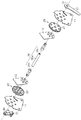
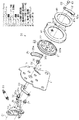
図1及び図2は、本実施形態に係る車両用シートリクライニング装置を示す分解斜視図である。同図に示すように、この装置は、シートクッション4の骨格をなす金属板からなるシートクッションフレーム11をシート幅方向で一対で備えるとともに、各シートクッションフレーム11には、シートバック5の骨格をなす金属板からなるシートバックフレーム12が、前記ロック機構20を介して回動軸O1を中心に回動自在に連結されている。なお、シートクッションフレーム11及びシートバックフレーム12の間に介在される各ロック機構20は、シートクッションフレーム11に対するシートバックフレーム12の回動(傾動)を規制するロック状態と、許容するアンロック状態とを切り替えるためのもので、基本的にロック状態を保持する。
1 and 2 are exploded perspective views showing a vehicle seat reclining device according to the present embodiment. As shown in the figure, this apparatus includes a pair of seat cushion frames 11 made of a metal plate that forms the skeleton of the seat cushion 4 in the seat width direction, and the skeleton of the seat back 5 is provided on each
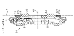
すなわち、図3の断面図で示したように、前記ロック機構20は、前記シートクッションフレーム11の内側面に溶接にて固着されるベース体としての円環状のロアプレート21を備えるとともに、前記シートバックフレーム12の外側面に溶接にて固着されて前記ロアプレート21に対し回動軸O1を中心に回動自在に支持された回動体としての円環状のアッパプレート22を備える。なお、アッパプレート22の内側面(シートバックフレーム12の対向面)は、段差凹凸部22cを有して段付き形状に成形されて環状の取付面22aを形成する。また、アッパプレート22の内周面は、内歯車22bを形成する。
That is, as shown in the sectional view of FIG. 3, the
ロアプレート21及びアッパプレート22の形成する内部空間には、回動軸O1を中心とする径方向に移動可能に装着されて前記内歯車22bに噛合可能な複数のポール23が収容されるとともに、これらポール23に係合されて回動軸O1を中心とする回動に伴い該ポール23を径方向に移動させるカム24が収容されている。つまり、各ロック機構20は、カム24の一側方向への回動に伴いポール23が径方向外側に移動して前記内歯車22bに噛合することでロック状態に切り替わる。あるいは、各ロック機構20は、カム24の他側方向への回動に伴いポール23が径方向内側に移動して前記内歯車22bとの噛合が解除されることでアンロック状態に切り替わる。なお、各ロック機構20は、ポール23を径方向外側(即ちロック側)に移動させる方向にカム24を回動付勢する渦巻きばねからなるスプリング25を備えており、該スプリング25に付勢されることで通常はロック状態を保持する。
The inner space formed by the
図1に示すように、回動軸O1に沿ってシート幅方向に延在する制御軸26は、パイプ状の本体部26aを有するとともに、該本体部26aの一側(図示右下側)の端部に溶接にて固着されて前記シートクッションフレーム11及び前記シートバックフレーム12ともども一方のロック機構20を貫通するヒンジ部位26bを有し、更に前記本体部26aの他側(図示左上側)の端部に溶接にて固着されて前記シートクッションフレーム11及び前記シートバックフレーム12ともども他方のロック機構20を貫通するヒンジ部位26cを有する。そして、各ヒンジ部位26b,26cは、対応するロック機構20のカム24と、例えば嵌合する態様で一体回動するように連結される。
As shown in FIG. 1, the
前記ヒンジ部位26bのシートクッションフレーム11から突出する先端には、金属板からなるロック解除操作レバー27の基端部が嵌合され溶接にて固着されている。従って、ロック解除操作レバー27の操作に伴い、一方のヒンジ部位26b(制御軸26)が回動軸O1を中心に回動すると、該ヒンジ部位26bと一体で対応するカム24が回動することでロック機構20がアンロック状態に切り替わる。同時に、本体部26aを介して一体化された他方のヒンジ部位26cが回動軸O1を中心に回動すると、該ヒンジ部位26cと一体で対応するカム24が回動することでロック機構20がアンロック状態に切り替わる。また、ロック解除操作レバー27の操作が解放されると、前記スプリング25に付勢されて両側のカム24が制御軸26(及びロック解除操作レバー27)ともども戻り回動し、ロック機構20がロック状態に切り替わる(復帰する)。
A proximal end portion of a lock
一方、前記ヒンジ部位26cのシートクッションフレーム11から突出する先端には、金属板からなるレバー部材31の基端部(嵌合孔46)が遊嵌されている。このレバー部材31は、メモリ操作レバー(図示略)とワイヤを介して連結されており、該メモリ操作レバーの操作に伴い回動軸O1を中心に回動する。従って、メモリ操作レバーの操作に伴い前記レバー部材31を介して他方のヒンジ部位26c(制御軸26)が回動軸O1を中心に回動すると、該ヒンジ部位26cと一体で対応するカム24が回動することでロック機構20がアンロック状態に切り替わる。同時に、本体部26aを介して一体化された一方のヒンジ部位26bが回動軸O1を中心に回動すると、該ヒンジ部位26bと一体で対応するカム24が回動することでロック機構20がアンロック状態に切り替わる。
On the other hand, the base end portion (fitting hole 46) of the
次に、前記レバー部材31等の構成するメモリ機構30について、図4の側面図を併せ参照して説明する。同図に示すように、前記シートクッションフレーム11には、前記ロック機構20の右下側で回動軸O1に平行な回動軸O2を中心に支持ピン32が軸支されるとともに、該支持ピン32のシートクッションフレーム11側の先端部は、扁平円状の嵌合部32a及び該嵌合部32aよりも縮径された扁平円状の嵌合部32bを順次形成する。そして、一方の嵌合部32aには、シートクッションフレーム11の外側(レバー部材31側)で、金属板からなるL字状のアーム部材33の基端部が嵌合するとともに、他方の嵌合部32bには、シートクッションフレーム11の内側(ロック機構20側)で、金属板からなる規制手段としての滴状のカム部材34の基端部が嵌合する。従って、アーム部材33及びカム部材34は、支持ピン32によりシートクッションフレーム11を挟んで一体回動するように連結されている。
Next, the
また、前記シートクッションフレーム11には、回動軸O1を中心とする周方向に円弧状に延在するとともに、図示時計回転方向に向かう側で前記カム部材34の先端部に臨む金属板からなる断面L字状の係合保持部としての噛合保持部材35が溶接にて固着されている。噛合保持部材35の回動軸O1を中心とする円弧状の内周面は、ガイド面35aを形成する。なお、噛合保持部材35には、前記カム部材34に臨んで切り欠き35bが形成され、前記カム部材34の先端部の回動軸O1側への進入を許容している。
The
さらに、前記シートクッションフレーム11には、回動軸O2(カム部材34)の左側で回動軸O1中心とする周方向に円弧状に延在する長孔状のガイド孔11aが形成されるとともに、該ガイド孔11aには、前記レバー部材31に突設されたガイドピン36が貫通する。従って、レバー部材31が回動軸O1を中心に回動すると、これに連動してガイドピン36がガイド孔11aに沿って移動する。
Further, the
前記アーム部材33の先端部には、回動軸O1と平行に前記レバー部材31側に突出する略円柱状のガイド部37が固着されている。一方、前記レバー部材31には、ガイド部37が挿入されるL字状の長穴38が形成されている。この長穴38は、回動軸O1(制御軸26)を中心とする周方向に延在する第1延在部としての第1長穴38aと、該第1長穴38aに連続して回動軸O1側に延びる第2延在部としての第2長穴38bとを有する。従って、アーム部材33は、ガイド部37が第1長穴38aにあるときに、ガイド部37を第1長穴38aに沿って相対移動(空走)させてレバー部材31の回動を許容するとともに、ガイド部37を第1長穴38aから第2長穴38bに進入させてレバー部材31の回動を規制する。あるいは、アーム部材33は、ガイド部37が第1長穴38aにあるときに、該第1長穴38aの内周面にガイド部37が挟まれることで、回動軸O2を中心とする回動が規制されるとともに、ガイド部37が第2長穴38bに進入することで該回動が許容される。
A substantially
本実施形態では、レバー部材31の図示時計回転方向の回動に際し、ガイド部37が第1長穴38aに沿って相対移動する間に、該レバー部材31に連動する制御軸26の回動により内歯車22b及びポール23(外歯)の両歯先が外れて前記ロック機構20の解除が辛うじて完了するように設定されている。これは、レバー部材31の回動に係るメモリ操作レバーの操作量(ストローク)を最小限に抑えて操作負荷を軽減するためである。このとき、アーム部材33は、前記カム部材34とともに回動軸O2を中心とする回動が規制されている。
In the present embodiment, when the
また、ガイド部37の進入した直後の第2長穴38bは、第1長穴38a側の回動軸O2までの距離よりも終端側の回動軸O2までの距離の方が短く設定されている。従って、レバー部材31は、前記ロック機構20の解除の完了後(アンロック状態への切り替え完了後)、ガイド部37が第2長穴38bの終端側に移動することで、ガイド部37に押圧されて図示時計回転方向、即ち前記ロック機構20をアンロック状態に切り替える方向に更に回動する。つまり、第2長穴38bは、アーム部材33の回動に伴いレバー部材31に連動する制御軸26がロック機構20をアンロック状態に切り替える方向に回動するようにガイド部37に押圧される押圧部38cを有する。ガイド部37が第2長穴38bを移動する間、レバー部材31が回動軸O1を中心に若干揺動するものの、ロック機構20をロック状態に切り替える方向に相当する回動は規制されている。なお、レバー部材31には、前記支持ピン32に一端の係止されたコイルスプリング39の他端が係止されており、該コイルスプリング39によりガイド部37が第1長穴38aの終端側に相対移動する方向、即ち前記ロック機構20をロック状態に切り替える方向に回動付勢されている。
Further, the second
前記アッパプレート22には、前記取付面22aに接合される態様で、金属板からなるリング状のプレート部としてのプレート部材40が固着されている。このプレート部材40の外周部には、係合部としての鋸波状の噛合部40aが形成されている。
A
また、前記ロック機構20を内周側に包囲する態様で、金属板からなる円環状のポール保持ブラケット41が前記制御軸26(回動軸O1)と同軸で回動自在に設けられている。すなわち、ポール保持ブラケット41は、前記段差凹凸部22cに軸支されており、シートバックフレーム12及びアッパプレート22の連結面C(図3参照)よりもシート幅方向でシートクッションフレーム11側に配置されている。このポール保持ブラケット41は、基本的に前記噛合保持部材35(ガイド面35a)の内径よりも小さい外径を有するとともに、その周壁は、図示右下側の角度位置で内周側に凹設されて係止凹部41aを形成する。ポール保持ブラケット41は、前記切り欠き35bから回動軸O1側に進入した前記カム部材34の先端部が嵌入可能になっており、前述の態様でカム部材34が回動規制されるときに該カム部材34の先端部が前記係止凹部41aに嵌入することで回動規制される。このときのポール保持ブラケット41の角度位置を初期位置という。
Further, an annular
なお、ポール保持ブラケット41は、係止凹部41aに対し図示反時計回転方向に向かう側でその周壁が径方向外側に湾出されており、係止凹部41aに臨むその先端は係止片41bを形成する。一方、前記シートクッションフレーム11には、係止片41bの図示時計回転方向の回動軌跡を遮るように突設された規制片11bが形成されている。従って、ポール保持ブラケット41は、係止片41bが規制片11bと係合することで図示時計回転方向の回動が規制される。このときのポール保持ブラケット41の角度位置は、前述の初期位置と一致する。つまり、初期位置におけるポール保持ブラケット41の図示時計回転方向の回動規制は、カム部材34及び規制片11bの協働で行われている。
The
前記ポール保持ブラケット41には、金属板からなるブラシ状のメモリポール42の基端部が、前記係止凹部41aの近傍に設けられた支持ピン43により回動軸O1に平行な回動軸O3を中心に回動自在に連結されている。このメモリポール42は、回動軸O3を中心とする図示時計回転方向の回動により前記プレート部材40(噛合部40a)と噛合可能な鋸波状のポール側噛合部42aを有している。なお、メモリポール42は、適宜の付勢手段(ばね等)により、プレート部材40に噛合する方向と逆方向(図示反時計回転方向)に付勢力(阻止力)が付与されている。
The
そして、メモリポール42は、その先端部からシートクッションフレーム11側に立設されたフランジが、その外側面側で前記ポール保持ブラケット41の角度位置に応じて前記ガイドピン36又は噛合保持部材35(ガイド面35a)に当接されることで図示反時計回転方向の回動が規制されている(図4〜図9参照)。また、ガイドピン36等に当接するメモリポール42のフランジは、回動軸O1(制御軸26)からの径方向の距離が近い第1面としての第1円弧部42bと、該回動軸O1からの径方向の距離が遠い第2面としての第2円弧部42cとを備え、これら第1及び第2円弧部42b,42cの間は、段部42dを介して連続している。第1及び第2円弧部42b,42cのそれぞれは、ガイドピン36が当接しているときに回動軸O1(制御軸26)を中心とする円弧形状を呈する。そして、メモリポール42は、レバー部材31の図示時計回転方向の回動に伴いガイドピン36が第1円弧部42bから第2円弧部42cに移動することで、段部42d分だけ回動軸O1側に移動すべく回動軸O3を中心に図示時計回転方向に回動し、ポール側噛合部42a及び噛合部40aの間で前記プレート部材40に噛合する。つまり、メモリポール42は、レバー部材31のガイドピン36が段部42dに位置することで、プレート部材40との係合・非係合状態が切り替わる。
The
また、メモリポール42は、前記プレート部材40に噛合した状態で、前述のフランジが噛合保持部材35に進入することでその噛合状態を維持する(図8〜図9参照)。従って、例えばプレート部材40が図示反時計回転方向(シートバックフレーム12が前傾する方向)に回動すると、これに噛合するメモリポール42がポール保持ブラケット41と一体で回動する。このとき、前記カム部材34は、前述の態様でアーム部材33と一体で図示時計回転方向に回動することで、ポール保持ブラケット41(係止凹部41a)との係合が外れる。また、プレート部材40が図示時計回転方向(シートバックフレーム12が後傾する方向)に回動すると、これに噛合するメモリポール42がポール保持ブラケット41と一体で回動する。このとき、ポール保持ブラケット41は、係止凹部41aにカム部材34の先端部が嵌入するとともに、係止片41bが規制片11bに当接されることで回動規制され、前述の初期位置に復帰する。
In addition, the
ここで、メモリ機構30の動作について総括して説明する。メモリ操作レバーに対する操作力が解放されており、図4に示すように、レバー部材31の第1長穴38aに配置されたガイド部37によりアーム部材33がカム部材34とともに回動規制されているとする。このとき、カム部材34は、先端部が前記係止凹部41aに嵌入することでポール保持ブラケット41の回動を規制する。
Here, the operation of the
この状態で、メモリ操作レバーの操作に伴い、レバー部材31が図示時計回転方向に回動すると、ロック機構20をアンロック状態に切り替えるべく、嵌合孔46に遊嵌されたヒンジ部位26c(制御軸26)が回動する。このとき、ガイド部37は、第1長穴38a内を相対的に移動するため、アーム部材33の回動規制がカム部材34とともに継続される。従って、カム部材34によるポール保持ブラケット41の回動規制も継続される。一方、レバー部材31に設けられたガイドピン36は、メモリポール42の第1円弧部42bから第2円弧部42cに移動することで、メモリポール42を図示時計回転方向に回動する側に押圧して、該メモリポール42を前記プレート部材40に噛合する。これにより、メモリポール42の連結されたポール保持ブラケット41は、プレート部材40(シートバックフレーム12)と一体回動するように連結される。そして、図5に示すように、ガイド部37が第1長穴38aの第2長穴38b側に達すると、ロック機構20のアンロック状態への切り替えが辛うじて完了する。ただし、ガイド部37は、未だ第2長穴38b内への進入が叶わず、アーム部材33の回動規制(ポール保持ブラケット41の回動規制)が依然として継続される。
In this state, when the
そして、引き続き、レバー部材31が図示時計回転方向に回動して、図6に示すように、ガイド部37が第2長穴38bにまさに達すると、アーム部材33の回動規制がカム部材34とともに解除される。従って、レバー部材31が図示時計回転方向に更に回動すると、図7に示すように、カム部材34によるポール保持ブラケット41の回動規制を解除すべくアーム部材33が回動し始める。同時に、前記噛合保持部材35は、メモリポール42のフランジがまさに達してその噛合状態の維持を始める。
Subsequently, when the
そして、この状態で、シートバック5(シートバックフレーム12)を最前方に傾動(前倒し)させるべく、アッパプレート22に接合されたプレート部材40を図示反時計回転方向に回動させると、図8に示すように、該プレート部材40に噛合されたメモリポール42とともにポール保持ブラケット41が一体回動する。このとき、噛合保持部材35によりメモリポール42の噛合状態が維持される。また、カム部材34は、ポール保持ブラケット41(係止凹部41a)との係合を外しつつ図示時計回転方向に回動するとともに、カム部材34と一体回動するアーム部材33は、これに伴いガイド部37を第2長穴38bの終端側に移動させる。このとき、レバー部材31は、第2長穴38b(押圧部38c)がガイド部37に押圧されて図示時計回転方向、即ちロック機構20をアンロック状態に切り替える方向に更に回動することは既述のとおりである。従って、シートバック5(シートバックフレーム12)の最前方に傾動に合わせて、ロック機構20をより確実にアンロック状態に切り替えるためのレバー部材31の余剰の操作量が確保されている。なお、ポール保持ブラケット41(係止凹部41a)との係合の外れたカム部材34は、ポール保持ブラケット41の周壁によって図示反時計回転方向への回動が規制される。
In this state, when the
一方、シートバック5(シートバックフレーム12)が最前方に傾動される直前の該シートバック5の角度位置に復帰させるべく、アッパプレート22に接合されたプレート部材40を図示時計回転方向に回動させると、図9に示すように、前述の態様で一体回動するポール保持ブラケット41(係止凹部41a)にカム部材34の先端部がまさに嵌入し始める。そして、前述の説明の逆順(図7、図6、図5)で図4に示す状態に復帰する。なお、前記レバー部材31は、ガイド部37が第1長穴38a内に進入することで、前記コイルスプリング39に付勢されてガイド部37が相対的に第1長穴38aの終端側に移動するように戻り回動する。
On the other hand, in order to return the seat back 5 (seat back frame 12) to the angular position of the seat back 5 just before tilting forward, the
次に、前記ロック解除操作レバー27の操作(回動)に基づくロック機構20の解除と、メモリ操作レバーの操作(レバー部材31の回動)に基づくロック機構20の解除との関係について説明する。
Next, the relationship between the release of the
図11に示すように、扁平円状のヒンジ部位26cに遊嵌されるレバー部材31の嵌合孔46は、周方向に拡張された連動禁止手段としての一対の遊び部46aを有して蝶形(即ちヒンジ部位26cの断面と異形)に成形されている。これにより、嵌合孔46におけるヒンジ部位26c(制御軸26)の所定範囲の相対回動が許容されている。そして、コイルスプリング39に付勢されて初期状態(図4の状態に相当)にあるレバー部材31の嵌合孔46は、図11(a)に示すように、ロック解除操作レバー27の操作に伴うヒンジ部位26c(制御軸26)の回動方向(図示時計回転方向)で前記遊び部46a分のヒンジ部位26cの相対回動を許容している。従って、図11(b)に示すように、ロック解除操作レバー27の操作(制御軸26の回動)に連動してレバー部材31が回動することはない。
As shown in FIG. 11, the
一方、前記嵌合孔46は、メモリ操作レバーの操作に伴う回動方向(図示時計回転方向)でヒンジ部位26cに当接している。従って、図11(c)に示すように、メモリ操作レバーの操作に伴うレバー部材31の回動に連動して嵌合孔46に押圧されるヒンジ部位26c(制御軸26)が直ちに回動し始め、ロック機構20のアンロック状態への切り替えが開始される。
On the other hand, the
以上詳述したように、本実施形態によれば、以下に示す効果が得られるようになる。
(1)本実施形態では、プレート部材40は、シートバックフレーム12と一体回動するロック機構20のアッパプレート22に固定されている。また、プレート部材40に噛合可能なメモリポール42は、制御軸26と同軸で回動自在なポール保持ブラケット41に連結されている。また、ポール保持ブラケット41を所定の初期位置に復帰させるカム部材34(及び規制片11b)は、シートクッションフレーム11に設けられている。さらに、メモリポール42とプレート部材40との噛合を保持等する噛合保持部材35は、シートクッションフレーム11に設けられている。さらにまた、メモリポール42及びプレート部材40の噛合とともに、ロック機構20のアンロック状態への切り替え等に係るレバー部材31の回動を、制御軸26と同軸にした。そして、レバー部材31(ガイドピン36)をメモリポール42に直に当接させて該メモリポール42及びプレート部材40を噛合するようにした。従って、基本的に、メモリ機構30をロック機構20(制御軸26)の周辺に配置する態様で前記連結面Cよりもシート幅方向でシートクッションフレーム11側に集約することができ、その組付性を向上することができる。つまり、メモリ機構30は、ロック機構20の周辺に全て集約されてユニット化されることで、その組付性を向上することができる。また、ロック機構20(制御軸26)は、メモリ機構30(レバー部材31)と連係されるものの、汎用品を使用することができる。
As described above in detail, according to the present embodiment, the following effects can be obtained.
(1) In the present embodiment, the
(2)本実施形態では、レバー部材31の回動に伴い該レバー部材31の当接部(ガイドピン36)を第1円弧部42bから第2円弧部42cに移動させる極めて簡易な構造で、メモリポール42をプレート部材40に噛合することができる。
(2) In the present embodiment, with the rotation of the
(3)本実施形態では、ガイド部37が第1長穴38aから第2長穴38bに進入すると、アーム部材33によりレバー部材31の回動が制御軸26ともども規制される。これにより、ロック機構20のアンロック状態を維持することができる。
(3) In this embodiment, when the
(4)本実施形態では、メモリポール42がプレート部材40に噛合した後、ロック機構20によるアンロック状態への切り替えが完了する。また、メモリポール42がプレート部材40に噛合した後、カム部材34とポール保持ブラケット41(係止凹部41a)との係合が外れて該ポール保持ブラケット41の回動が許容される。従って、メモリ機構30の誤作動を抑制することができる。
(4) In this embodiment, after the
(5)例えば特開2002−209661号公報に記載の装置では、リクライニングのロック機構のロック・アンロック状態の切り替えに係る通常のロック解除操作レバー(第1操作レバー)と、メモリ作動の切り替えに係るメモリ操作レバー(第2操作レバー)とを備えており、該メモリ操作レバーの操作時にはロック解除操作レバーとともに作動する。従って、メモリ操作レバーを、ロック解除操作レバーに対しシートの同じ側に配置する必要があり、操作性が悪くなる。また、メモリ操作レバーの配置の自由度が低減されるとともに、配置のために要するスペースも増加する。これに対し、本実施形態では、嵌合孔46の遊び部46aにより、レバー部材31は、ロック解除操作レバー27の操作に伴う制御軸26の回動と連動しないため、レバー部材31の作動に係るメモリ操作レバーを、ロック解除操作レバー27に対しシートの異なる側に配置することができ、ひいては操作性を向上することができる。また、各操作レバー等の配置自由度を向上することができる。
(5) For example, in the device described in Japanese Patent Application Laid-Open No. 2002-209661, the normal unlocking operation lever (first operation lever) for switching the lock / unlock state of the reclining lock mechanism and the switching of the memory operation are used. The memory operation lever (second operation lever) is provided and operates together with the unlock operation lever when the memory operation lever is operated. Therefore, it is necessary to arrange the memory operation lever on the same side of the seat with respect to the unlocking operation lever, and the operability is deteriorated. In addition, the degree of freedom of arrangement of the memory operation lever is reduced, and the space required for arrangement increases. On the other hand, in the present embodiment, the
(6)例えば特開平11−70027号公報に記載の装置では、リクライニングのロック機構のロック・アンロック状態の切り替えに係る通常のロック解除操作レバーと、メモリ作動の切り替えに係るメモリ操作レバーとを備えており、シートの左右両側に配設されたロック機構を繋ぐロッドに遊びを設けることで、シートの互いに反対側に配置された各操作レバーの作動角を変化させている。この場合、両側に配設されたロック機構を繋ぐロッドに遊びを設ける機構が必要となり、軸が不安定になってロック機構自体の性能が劣化する可能性がある。また、この遊びを設ける機構の配置スペースが必要になるとともに、部品点数も増加してしまう。これに対し、本実施形態では、嵌合孔46の遊び部46aを採用することで、制御軸に遊び部を設ける機構が必要なく、例えば軸ずれ等のロック機構の性能劣化を回避することができる。
(6) For example, in the device described in Japanese Patent Application Laid-Open No. 11-70027, a normal unlocking operation lever related to switching of the lock / unlock state of the reclining lock mechanism and a memory operating lever related to switching of the memory operation are provided. The operation angle of each operation lever disposed on the opposite side of the seat is changed by providing play in the rod that connects the lock mechanisms disposed on the left and right sides of the seat. In this case, a mechanism for providing play on the rod connecting the lock mechanisms disposed on both sides is required, which may cause the shaft to become unstable and degrade the performance of the lock mechanism itself. In addition, an arrangement space for the mechanism for providing this play is required, and the number of parts increases. On the other hand, in this embodiment, by adopting the
(7)本実施形態では、ポール保持ブラケット41(シートバックフレーム12)に連動するアーム部材33の回動に伴いガイド部37に第2長穴38bの押圧部38cが押圧され、レバー部材31に連動する制御軸26がロック機構20をアンロック状態に切り替える方向に更に回動することで、メモリ操作レバーの操作量を徒に増やすことなく、ロック機構20をより確実にアンロック状態に切り替えることができる。特に、ガイド部37が第2長穴38bの終端側に移動するアーム部材33の回動を、シートバック5の前倒しに係る付勢手段6で付勢することで、レバー部材31を回動しやすくしてメモリ操作レバーの操作に要する操作力を軽減することができる。
(7) In the present embodiment, the
(8)例えば特開2006−304832号公報に記載の装置では、ロック機構に強度が必要とされることはもちろんのこと、メモリ機構にも同様の強度が必要とされる。これは、通常のリクライニング作動時(メモリ解除時)にロック機構及びメモリ機構が一体化して作動し、一方、ウォークイン作動時(メモリ作動時)にロック機構のみ作動し、元に戻すときに作動しなかったメモリ機構と一体化する位置を記憶位置とする構造を採用しているためである。これに対し、本実施形態では、通常のリクライニング作動時(メモリ解除時)にロック機構20のみ作動し、一方、ウォークイン作動時(メモリ作動時)にロック機構20及びメモリ機構30が一体化して作動し、これらロック機構20及びメモリ機構30が一体化する位置を記憶位置とする構造を採用している。従って、メモリ機構30は、基本的にロック機構20と係合し得る強度を満たせばよい。
(8) For example, in the device described in Japanese Patent Application Laid-Open No. 2006-304832, not only the locking mechanism requires strength but also the memory mechanism requires similar strength. This is because the locking mechanism and the memory mechanism operate integrally during normal reclining operation (when the memory is released), while only the locking mechanism operates during the walk-in operation (when the memory is operating) and operates when returning to the original state. This is because a structure in which the position integrated with the memory mechanism that has not been used is a storage position is employed. On the other hand, in the present embodiment, only the
(9)ポール保持ブラケット41は、アッパブラケット22の段差凹凸部22cに軸支されている。従って、ロック機構20のシート幅方向の厚みを利用してポール保持ブラケット41を配置することができ、メモリ機構30のシート幅方向への大型化を抑制することができる。
(9) The
(10)噛合保持部材35をレバー部材31と別に設けたことで、これら噛合保持部材35及びレバー部材31をシートクッションフレーム11の内側及び外側にそれぞれ配置することができ、省スペース化及びユニット化を容易に行うことができる。
(10) Since the
なお、上記実施形態は以下のように変更してもよい。
・前記実施形態において、ポール保持ブラケット41の回動規制に係る係止片41b及び規制片11bは割愛してもよい。
In addition, you may change the said embodiment as follows.
In the above-described embodiment, the
・前記実施形態において、噛合保持部材35をシートクッションフレーム11に一体形成してもよい。
・前記実施形態においては、プレート部材40とメモリポール42との噛合状態を維持するための噛合保持部材35(ガイド面35a)をシートクッションフレーム11に設けた。これに対し、配置スペースの制約や動作への影響がなければ、噛合保持部材35をレバー部材31に設けてもよい。
In the embodiment, the
In the above embodiment, the
・前記実施形態においては、制御軸26のヒンジ部位26bをロック解除操作レバー27の基端部に固着した。これに対し、制御軸26のヒンジ部位26bをロック解除操作レバー27の基端部に形成した嵌合孔に遊嵌してもよい。この場合、メモリ操作レバーの操作(レバー部材31の回動)に伴うヒンジ部位26b(制御軸26)の回動方向(図示時計回転方向)で遊び部分のヒンジ部位26bの相対回動を許容することで、メモリ操作レバーの操作(制御軸26の回動)に連動したロック解除操作レバー27の回動を回避することができる。
In the embodiment, the
・第1及び第2面として、第1及び第2円弧部42b,42cに代えて、適宜の曲面や平面を採用してもよい。
・第1及び第2延在部として、第1及び第2長穴38a,38bに代えて、ガイド部37を案内する壁部を採用してもよい。
-As a 1st and 2nd surface, it may replace with the 1st and 2nd
-As a 1st and 2nd extension part, it replaces with the 1st and 2nd
・前記実施形態において、メモリポール42は、プレート部材40に噛合する方向に付勢されていてもよい。この場合、例えばメモリ操作レバーに設けられたピン等のストッパ機能による阻止力の付与でメモリポール42及びプレート部材40の噛合を禁止するとともに、メモリ操作レバーの作動でストッパ機能を解除(阻止力を解消)することでメモリポール42及びプレート部材40を噛合させる。あるいは、メモリポール42にガイド孔を設け、レバー部材31にガイド孔にガイドされるピンを設けることで、メモリポール42に付勢力を付与することなく、レバー部材31の回動でメモリポール42の噛合・非噛合状態を変更してもよい。
In the embodiment, the
・前記実施形態において、プレート部材40を割愛してその係合部(噛合部40a)をアッパプレート22に一体形成してもよい。
・前記実施形態において、プレート部材40及びメモリポール42は、例えば噛合部に代えて設けた摩擦材による摩擦係合によって係合状態にしてもよい。
In the embodiment, the
In the above-described embodiment, the
・前記実施形態においては、シートバックフレーム12(シートバック)の前傾しによって最終傾斜位置となる場合について説明した。これに対し、シートバックフレーム12(シートバック)の後傾しによって最終傾斜位置となるようにしてもよい。 In the embodiment described above, the case where the seatback frame 12 (seatback) is tilted forward to reach the final tilt position has been described. On the other hand, the final tilt position may be obtained by backward tilting of the seat back frame 12 (seat back).
・前記実施形態において、ロック解除操作レバー27自体は、ヒンジ部位26bに固着されることなく遊びを持ってこれに嵌合され、他の部品で挟み込んでロック解除操作レバー27を固定してもよい。
In the above-described embodiment, the unlocking
・前記実施形態において、レバー部材31の回動中心は、制御軸26と同軸でなくてもよい。
・前記実施形態において、ポール保持ブラケット41は、ロアプレート21に設けた段差凹凸部に軸支してもよい。
In the embodiment, the rotation center of the
In the embodiment described above, the
・前記実施形態において、レバー部材31は、メモリ操作レバーと一体形成されていてもよい。
・前記実施形態では、メモリ機能に係るレバー部材31の嵌合孔46に遊び部46aを設定して、ロック解除操作レバー27による通常のリクライニング操作(ロック機構20の解除)に連動して、メモリ操作レバーが作動しないように構成した。これに対し、ロック解除操作レバー27に連係されるウォークイン機能や車両シートの収納機能等に係る操作レバーを備える場合には、同様にしてロック解除操作レバー27による通常のリクライニング操作に連動して当該操作レバーが作動しないように構成してもよい。また、当該操作レバーによる所定の操作に連動してロック解除操作レバー27が作動しないように構成してもよい。いずれの場合であっても、各機能(メモリ機能、ウォークイン機能、収納機能)の設置されたシート又は割愛されたシートの互換性を向上することができる。
In the embodiment, the
In the embodiment, the
1…車両シート、11…シートクッションフレーム、11b…係止片(規制手段)、12…シートバックフレーム、20…ロック機構、21…ロアプレート(ベース体)、22…アッパプレート(回動体)、22c…段差凹凸部、26…制御軸、26b,26c…ヒンジ部位、27…ロック解除操作レバー、30…メモリ機構、31…レバー部材、33…アーム部材、34…カム部材(規制手段)、35…噛合保持部材(係合保持部)、36…ガイドピン(当接部)、37…ガイド部、38…長穴、38a…第1長穴(第1延在部)、38b…第2長穴(第2延在部)、38c…押圧部、40…プレート部材(プレート部)、40a…噛合部(係合部)、41…ポール保持ブラケット、42…メモリポール、42b…第1円弧部(第1面)、42c…第2円弧部(第2面)、42d…段部、46…嵌合孔、46a…遊び部(連動禁止手段)。 DESCRIPTION OF SYMBOLS 1 ... Vehicle seat, 11 ... Seat cushion frame, 11b ... Locking piece (regulation means), 12 ... Seat back frame, 20 ... Lock mechanism, 21 ... Lower plate (base body), 22 ... Upper plate (rotating body), 22c ... Stepped uneven portion, 26 ... Control shaft, 26b, 26c ... Hinge part, 27 ... Unlock operation lever, 30 ... Memory mechanism, 31 ... Lever member, 33 ... Arm member, 34 ... Cam member (regulating means), 35 ... meshing holding member (engagement holding part), 36 ... guide pin (contact part), 37 ... guide part, 38 ... long hole, 38a ... first long hole (first extension part), 38b ... second long Hole (second extending portion), 38c ... Pressing portion, 40 ... Plate member (plate portion), 40a ... Mating portion (engaging portion), 41 ... Pole holding bracket, 42 ... Memory pole, 42b ... First arc portion (First side), 2c ... second arcuate portion (second surface), 42d ... step portion, 46 ... fitting hole, 46a ... play portion (interlock inhibiting means).
Claims (9)
メモリ操作レバーの操作に伴い、前記ロック機構のロック状態における前記シートクッションフレームに対する前記シートバックフレームの角度位置を記憶するとともに、前記ロック機構をアンロック状態に切り替えて所定傾斜位置への前記シートバックフレームの傾動を可能とするメモリ機構とを有する車両用シートリクライニング装置において、
前記メモリ機構は、
前記回動体に設けられた、係合部を有するプレート部と、
前記シートバックフレームと前記回動体との連結面よりもシート幅方向において前記シートクッションフレーム側に配置され、前記制御軸と同一の回動軸線の周りで回動自在なポール保持ブラケットと、
前記ポール保持ブラケットに回動自在に連結され、前記プレート部の前記係合部に係合可能であるとともに、該係合部との係合を阻止する阻止力の付与されたメモリポールと、
前記ポール保持ブラケットが前記シートバックフレームの前記所定傾斜位置への傾動方向とは逆方向へ回動することを規制して該ポール保持ブラケットを所定の初期位置に復帰させる規制手段と、
前記メモリポールに付与される前記阻止力に抗し又は該阻止力を解消して前記メモリポールを前記プレート部に係合させるとともに、前記制御軸を連動させて前記ロック機構をアンロック状態に切り替えかつ該アンロック状態を維持するよう、前記メモリ操作レバーの操作に伴って回動するレバー部材と、
前記シートバックフレームを前記所定傾斜位置に至るまで傾動させるために前記ポール保持ブラケットを回動させる場合は前記メモリポールと前記プレート部との係合を保持するとともに、前記ポール保持ブラケットの前記初期位置への復帰に伴い前記メモリポールと前記プレート部との係合を解除可能な係合保持部とを備えたことを特徴とする車両用シートリクライニング装置。 Is interposed between the seat cushion frame and the seat back frame, the lock state tilting for restricting the tilting of the seat back frame for said seat cushion frame by the rotation of the control shaft associated with operation of the lock releasing lever a selectively switched that the lock mechanism to the unlocked state tolerated, a base body fixed to the seat cushion frame, rotatably relative to the base body is fixed to the seat back frame A lock body that is supported, and the lock mechanism in which the control shaft and the rotation shaft rotate around the same rotation axis ;
With the operation of the memory operation lever, the angular position of the seat back frame with respect to the seat cushion frame in the locked state of the lock mechanism is stored, and the lock mechanism is switched to the unlocked state and the seat back to a predetermined tilt position In a vehicle seat reclining device having a memory mechanism capable of tilting a frame,
The memory mechanism is
Before provided Machinery body, a plate portion having an engaging portion,
A pole holding bracket that is disposed on the seat cushion frame side in the seat width direction with respect to a connecting surface between the seat back frame and the rotating body, and is rotatable around the same rotation axis as the control shaft;
Rotatably connected to the holding bracket, with is engageable with the engaging portion of the front Symbol plate portion, a memory pole granted blocking force to block the engagement between the engaging portion,
And regulating means for the holding bracket is to return to the predetermined initial position the holding bracket to restrict that rotates in the opposite direction to the tilting direction to a predetermined inclined position of the seat back frame,
The against the blocking force or to eliminate the blocking force to engage said memory pawl to said plate portion Rutotomoni, in conjunction with the control shaft unlock the locking mechanism condition being granted prior Symbol memory pole a lever member that rotates to switch and to maintain the unlocked state, with the operation of the memory operation lever,
Together when rotating the holding bracket for tilting up the seat back frame to the predetermined inclination position holds the engagement between the memory pole and the plate portion, the initial position of the holding bracket A vehicle seat reclining device comprising: an engagement holding portion capable of releasing the engagement between the memory pole and the plate portion when returning to the state.
前記ポール保持ブラケットは、前記ベース体又は前記回動体に形成された段差凹凸部に軸支されていることを特徴とする車両用シートリクライニング装置。 The vehicle seat reclining device according to claim 1,
The vehicle seat reclining device, wherein the pole holding bracket is pivotally supported by a stepped uneven portion formed on the base body or the rotating body.
前記レバー部材は、前記メモリ操作レバーの操作に伴って回動するとき前記メモリポールに当接し、それにより該メモリポールに付与される阻止力に抗し又は該阻止力を解消して前記メモリポールを前記プレート部に係合させ、
前記メモリポールは、前記制御軸の回動軸線からの径方向距離が小さい第1面と、前記制御軸の回動軸線からの径方向距離が前記第1面よりも大きい第2面と、これら第1面及び第2面の間に配置された段部と、を有し、
前記レバー部材は、前記第1面、前記第2面及び前記段部に当接可能な当接部を有し、該当接部が前記レバー部材の回動に伴い前記段部を介して前記第1面から前記第2面に、或いは前記第2面から前記第1面に移動することで、前記メモリポールが前記プレート部に対して係合する状態と係合しない状態とに切り替わることを特徴とする車両用シートリクライニング装置。 The vehicle seat reclining device according to claim 1 or 2,
The lever member abuts on the memory pole when rotating in accordance with the operation of the memory operation lever , thereby resisting or canceling the blocking force applied to the memory pole. It was engaged with the plate portion,
The memory pawl has a radial distance smaller first face from the rotation axis of the control shaft, and the second surface radial distance is greater than the first surface from the pivot axis of the control shaft, this has a step portion disposed between these first and second surfaces, a,
Said lever member, said first surface having said contact portion capable of contacting the second surface and the stepped portion, the abutment portion via the entailment before Kidan portion to the rotation of the lever member the second surface from said first surface, or by moving from the second surface to the first surface, said memory pawl is switched into a state that does not engage the state to be engaged to said plate portion A vehicle seat reclining device.
前記レバー部材は、前記制御軸の回動軸線を中心として周方向に沿って延在する第1延在部と、該第1延在部に連続して前記制御軸に向かって延びる第2延在部とを有し、
前記メモリ機構は、前記シートクッションフレームに回動可能に連結されたアーム部材を備え、該アーム部材は、前記第1及び第2延在部に挿入されるガイド部を有し、前記アーム部材は、前記ガイド部が前記第1延在部に位置する場合には前記レバー部材の回動を許容するとともに、前記ガイド部が前記第2延在部に進入した場合には前記レバー部材の回動を規制することを特徴とする車両用シートリクライニング装置。 In the vehicle seat reclining device according to any one of claims 1 to 3,
Said lever member includes a first extending portion extending along the circumferential direction around the rotation axis of the control shaft, a continuously to the first extending portion extending toward the control shaft Two extending parts,
The memory mechanism includes an arm member rotatably connected to the seat cushion frame, the arm member having a guide portion inserted into the first and second extending portions, and the arm member is , together with the permit pivoting of the lever member when the guide portion is positioned at the first extending portion, when the guide portion enters the second extended portion is rotation of the lever member vehicle seat reclining device according to claim and Turkey to regulate.
前記規制手段は、前記アーム部材と一体回動するように連結され、かつ前記ポール保持ブラケットの前記初期位置への復帰に伴い該ポール保持ブラケットと係合可能なカム部材を備え、
前記メモリポールが前記プレート部に係合した後、前記ガイド部を前記第2延在部に移動させつつ前記アーム部材が回動することで、前記ポール保持ブラケットに対する前記カム部材の係合が外れることを特徴とする車両用シートリクライニング装置。 The vehicle seat reclining device according to claim 4,
The restricting means includes a cam member that is coupled so as to rotate integrally with the arm member, and that can be engaged with the pole holding bracket as the pole holding bracket returns to the initial position.
After pre-Symbol memory pole is engaged with the plate portion, that said arm member while moving the guide portion to the second extending portion is rotated, the engagement of the cam member with respect to the holding bracket is A vehicle seat reclining device, wherein the vehicle seat reclining device is disengaged.
前記係合保持部は、前記シートクッションフレームに設けられており、
前記所定傾斜位置への前記ポール保持ブラケットの回動の当初は、前記レバー部材の当接部が前記メモリポールと前記プレート部との係合を保持し、その後、前記係合保持部が前記メモリポールと前記プレート部との係合を保持することを特徴とする車両用シートリクライニング装置。 In the vehicle seat reclining device according to any one of claims 1 to 5,
The engagement holding portion is provided on the seat cushion frame,
Said initial rotation before Symbol holding bracket to the predetermined inclination position, the abutment portion of the lever member maintains the engagement between the memory pole and the plate portion, then, the engagement holding portion is the vehicle seat reclining device comprising that you hold the engagement between the memory pole and the plate portion.
前記レバー部材は、前記ロック解除操作レバーの操作に伴う前記制御軸の回動時に前記レバー部材が前記制御軸と連動するのを禁止する連動禁止手段を備えたことを特徴とする車両用シートリクライニング装置。 In the vehicle seat reclining device according to any one of claims 1 to 6,
The vehicle seat reclining , wherein the lever member includes interlock prohibiting means for prohibiting the lever member from interlocking with the control shaft when the control shaft is rotated in accordance with an operation of the unlocking operation lever. apparatus.
前記制御軸は、一端部に第1ヒンジ部位を有しかつ他端部に第2ヒンジ部位を有し、
前記第1ヒンジ部位は前記ロック解除操作レバーに連結され、
前記第2ヒンジ部位は前記レバー部材の嵌合孔に嵌合し、
前記連動禁止手段は、前記ロック解除操作レバーの操作に伴う前記制御軸の回動方向に設定された前記嵌合孔の遊び部であることを特徴とする車両用シートリクライニング装置。 The vehicle seat reclining device according to claim 7,
The control shaft has a second hinge portion in and the other end portion has a first hinge portion to one end,
The first hinge part is connected to the unlocking lever;
Said second hinge portion is engaged with the engagement hole of the lever member,
The vehicle seat reclining device, wherein the interlock prohibiting means is a play portion of the fitting hole set in a rotation direction of the control shaft in accordance with an operation of the unlock operation lever.
前記第2延在部は、前記アーム部材の回動に伴い前記ガイド部に押圧される押圧部を有し、該押圧部は、前記レバー部材に連動する前記制御軸が前記ロック機構をアンロック状態に切り替えるように回動するよう、前記ガイド部に押圧されることを特徴とする車両用シートリクライニング装置。 The vehicle seat reclining device according to claim 4 or 5,
The second extending portion has a pressing portion that will be pressed against the guide portion in accordance with the rotation of the arm member, the pressing portion may unlock the control shaft the locking mechanism interlocked with the lever member to rotate to switch the state, the vehicle seat reclining device according to the pressed feature and Turkey to the guide portion.
Priority Applications (6)
| Application Number | Priority Date | Filing Date | Title |
|---|---|---|---|
| JP2008185000A JP4853501B2 (en) | 2008-07-16 | 2008-07-16 | Vehicle seat reclining device |
| PCT/JP2009/062000 WO2010007885A1 (en) | 2008-07-16 | 2009-06-30 | Seat reclining device for vehicle |
| EP09797813A EP2305070B1 (en) | 2008-07-16 | 2009-06-30 | Seat reclining device for vehicle |
| US13/054,267 US8033607B2 (en) | 2008-07-16 | 2009-06-30 | Seat reclining device for vehicle |
| AT09797813T ATE556622T1 (en) | 2008-07-16 | 2009-06-30 | SEAT TILT DEVICE FOR A VEHICLE |
| CN200980127196.8A CN102088890B (en) | 2008-07-16 | 2009-06-30 | Seat reclining device for vehicle |
Applications Claiming Priority (1)
| Application Number | Priority Date | Filing Date | Title |
|---|---|---|---|
| JP2008185000A JP4853501B2 (en) | 2008-07-16 | 2008-07-16 | Vehicle seat reclining device |
Publications (3)
| Publication Number | Publication Date |
|---|---|
| JP2010022471A JP2010022471A (en) | 2010-02-04 |
| JP2010022471A5 JP2010022471A5 (en) | 2011-10-06 |
| JP4853501B2 true JP4853501B2 (en) | 2012-01-11 |
Family
ID=41550293
Family Applications (1)
| Application Number | Title | Priority Date | Filing Date |
|---|---|---|---|
| JP2008185000A Expired - Fee Related JP4853501B2 (en) | 2008-07-16 | 2008-07-16 | Vehicle seat reclining device |
Country Status (6)
| Country | Link |
|---|---|
| US (1) | US8033607B2 (en) |
| EP (1) | EP2305070B1 (en) |
| JP (1) | JP4853501B2 (en) |
| CN (1) | CN102088890B (en) |
| AT (1) | ATE556622T1 (en) |
| WO (1) | WO2010007885A1 (en) |
Families Citing this family (24)
| Publication number | Priority date | Publication date | Assignee | Title |
|---|---|---|---|---|
| JP4853501B2 (en) * | 2008-07-16 | 2012-01-11 | アイシン精機株式会社 | Vehicle seat reclining device |
| CA2799234C (en) * | 2010-05-17 | 2018-01-16 | Magna Seating Inc. | Vehicle seat assembly with easy-entry mechanism |
| US8556340B2 (en) * | 2010-08-03 | 2013-10-15 | Lear Corporation | Vehicle seat recliner mechanism with selective torque transmission connectors |
| JP5707817B2 (en) * | 2010-09-28 | 2015-04-30 | アイシン精機株式会社 | Vehicle seat reclining device |
| DE102011106284B4 (en) * | 2011-07-01 | 2022-10-20 | Keiper Seating Mechanisms Co., Ltd. | Fitting system for a vehicle seat and vehicle seat |
| US20130076094A1 (en) * | 2011-09-27 | 2013-03-28 | Imasen Electric Industrial Co., Ltd. | Reclining apparatus |
| US9073458B2 (en) * | 2011-11-04 | 2015-07-07 | Aisin Seiki Company, Ltd. | Vehicle seat apparatus |
| US8864234B2 (en) | 2012-05-30 | 2014-10-21 | Lear Corporation | Discontinuous recliner with movable internal memory stop |
| FR2992912B1 (en) * | 2012-07-03 | 2014-07-11 | Renault Sa | SEAT BACK FOLDING DEVICE |
| JP6223901B2 (en) * | 2014-04-25 | 2017-11-01 | トヨタ紡織株式会社 | Vehicle seat |
| JP6196185B2 (en) * | 2014-04-25 | 2017-09-13 | トヨタ紡織株式会社 | Vehicle seat and manufacturing method thereof |
| JP6318934B2 (en) * | 2014-07-14 | 2018-05-09 | アイシン精機株式会社 | Vehicle seat reclining device |
| JP6379772B2 (en) * | 2014-07-14 | 2018-08-29 | アイシン精機株式会社 | Vehicle seat reclining device |
| US20170151893A1 (en) * | 2014-07-14 | 2017-06-01 | Aisin Seiki Kabushiki Kaisha | Seat reclining device for vehicle |
| JP6379773B2 (en) | 2014-07-14 | 2018-08-29 | アイシン精機株式会社 | Vehicle seat reclining device |
| JP6318935B2 (en) * | 2014-07-14 | 2018-05-09 | アイシン精機株式会社 | Vehicle seat reclining device |
| WO2016009875A1 (en) * | 2014-07-14 | 2016-01-21 | アイシン精機 株式会社 | Seat reclining device for vehicle |
| JP6318936B2 (en) * | 2014-07-14 | 2018-05-09 | アイシン精機株式会社 | Vehicle seat reclining device |
| WO2016084471A1 (en) * | 2014-11-26 | 2016-06-02 | アイシン精機 株式会社 | Seat reclining device for vehicle |
| JP6417897B2 (en) * | 2014-11-26 | 2018-11-07 | アイシン精機株式会社 | Vehicle seat reclining device |
| JP6327129B2 (en) * | 2014-11-26 | 2018-05-23 | アイシン精機株式会社 | Vehicle seat reclining device |
| JP6809161B2 (en) * | 2016-11-21 | 2021-01-06 | トヨタ紡織株式会社 | Vehicle seat |
| US10611273B2 (en) * | 2017-10-09 | 2020-04-07 | Faurecia Automotive Seating, Llc | Recliner system for a vehicle seat |
| JP7338522B2 (en) | 2020-03-13 | 2023-09-05 | トヨタ紡織株式会社 | vehicle seat |
Family Cites Families (19)
| Publication number | Priority date | Publication date | Assignee | Title |
|---|---|---|---|---|
| JPS612809A (en) * | 1984-06-18 | 1986-01-08 | アイシン精機株式会社 | Inclined angle adjusting apparatus |
| JPH05237016A (en) * | 1991-07-15 | 1993-09-17 | Shiroki Corp | Reclining mechanism |
| FR2722150B1 (en) * | 1994-07-05 | 1996-09-27 | Cesa | ARTICULATION WITH SEAT ADJUSTMENT POSITION |
| FR2722739B1 (en) * | 1994-07-22 | 1996-09-27 | Faure Bertrand Equipements Sa | IMPROVEMENTS ON JOINTS FOR VEHICLE SEATS |
| FR2766137B1 (en) | 1997-07-15 | 1999-10-01 | Faure Bertrand Equipements Sa | VEHICLE SEAT HAVING A JOINT MECHANISM |
| DE19960878A1 (en) * | 1999-12-17 | 2001-07-05 | Keiper Gmbh & Co | Locking fitting for a vehicle seat, in particular for a motor vehicle seat |
| JP4622104B2 (en) * | 2001-01-23 | 2011-02-02 | トヨタ紡織株式会社 | Reclining device |
| JP2005137893A (en) * | 2003-10-17 | 2005-06-02 | Aisin Seiki Co Ltd | Seat device for vehicle |
| JP4517345B2 (en) * | 2004-06-28 | 2010-08-04 | アイシン精機株式会社 | Reclining device |
| FR2879974B1 (en) * | 2004-12-23 | 2010-09-17 | Hammerstein Gmbh C Rob | ADVANCABLE VEHICLE SEAT WITH A BATI AND TWO PAIRS OF RAILS |
| JP4534828B2 (en) * | 2005-03-24 | 2010-09-01 | アイシン精機株式会社 | Vehicle seat device |
| JP2006271581A (en) * | 2005-03-29 | 2006-10-12 | Tachi S Co Ltd | Memory mechanism of seat reclining device |
| JP4652111B2 (en) | 2005-04-26 | 2011-03-16 | シロキ工業株式会社 | Seat reclining device |
| JP4661361B2 (en) * | 2005-05-26 | 2011-03-30 | トヨタ紡織株式会社 | Seat reclining device |
| JP4894192B2 (en) * | 2005-08-05 | 2012-03-14 | アイシン精機株式会社 | Vehicle seat |
| US7441840B2 (en) * | 2005-11-07 | 2008-10-28 | Aisin Seiki Kabushiki Kaisha | Reclining apparatus for vehicle seat |
| FR2913927B1 (en) * | 2007-03-20 | 2009-07-03 | Faurecia Sieges Automobile | ARTICULATION MECHANISM AND VEHICLE SEAT COMPRISING SUCH A MECHANISM |
| JP4853501B2 (en) * | 2008-07-16 | 2012-01-11 | アイシン精機株式会社 | Vehicle seat reclining device |
| JP5251326B2 (en) * | 2008-07-16 | 2013-07-31 | アイシン精機株式会社 | Vehicle seat operating device and vehicle seat reclining device |
-
2008
- 2008-07-16 JP JP2008185000A patent/JP4853501B2/en not_active Expired - Fee Related
-
2009
- 2009-06-30 CN CN200980127196.8A patent/CN102088890B/en not_active Expired - Fee Related
- 2009-06-30 EP EP09797813A patent/EP2305070B1/en not_active Not-in-force
- 2009-06-30 AT AT09797813T patent/ATE556622T1/en active
- 2009-06-30 US US13/054,267 patent/US8033607B2/en not_active Expired - Fee Related
- 2009-06-30 WO PCT/JP2009/062000 patent/WO2010007885A1/en active Application Filing
Also Published As
| Publication number | Publication date |
|---|---|
| EP2305070A4 (en) | 2011-11-02 |
| ATE556622T1 (en) | 2012-05-15 |
| US20110109142A1 (en) | 2011-05-12 |
| EP2305070B1 (en) | 2012-05-09 |
| CN102088890B (en) | 2013-05-01 |
| EP2305070A1 (en) | 2011-04-06 |
| JP2010022471A (en) | 2010-02-04 |
| CN102088890A (en) | 2011-06-08 |
| WO2010007885A1 (en) | 2010-01-21 |
| US8033607B2 (en) | 2011-10-11 |
Similar Documents
| Publication | Publication Date | Title |
|---|---|---|
| JP4853501B2 (en) | Vehicle seat reclining device | |
| JP5251326B2 (en) | Vehicle seat operating device and vehicle seat reclining device | |
| JP5614332B2 (en) | Vehicle locking device | |
| US7416255B2 (en) | Seat reclining apparatus for vehicle | |
| WO2012096357A1 (en) | Seat reclining device and seat device | |
| JP2007125116A (en) | Seat reclining device | |
| JP4895084B2 (en) | Seat reclining device | |
| US10427576B2 (en) | Seat reclining apparatus | |
| JP2008247187A (en) | Seat device for vehicle | |
| JP5641227B2 (en) | Seat reclining device and seat device | |
| WO2016009877A1 (en) | Seat reclining device for vehicle | |
| JP5505317B2 (en) | Vehicle seat device | |
| WO2016084471A1 (en) | Seat reclining device for vehicle | |
| JP2007252451A (en) | Seat reclining device of vehicle | |
| JP5780123B2 (en) | Ottoman device for vehicle | |
| JP2020196391A (en) | Vehicle seat | |
| JP2018164564A (en) | Seat reclining device | |
| JP4517748B2 (en) | Vehicle seat reclining device | |
| JP6379772B2 (en) | Vehicle seat reclining device | |
| JP5817436B2 (en) | Reclining device | |
| WO2014038678A1 (en) | Vehicle seat | |
| JP5515883B2 (en) | Actuating mechanism for vehicle seat adjusting device and vehicle seat reclining device | |
| JP2010173515A (en) | Structure for assembling operational cable to cylindrical case | |
| JP2014040137A (en) | Vehicle seat | |
| JP2014040134A (en) | Vehicle seat |
Legal Events
| Date | Code | Title | Description |
|---|---|---|---|
| A621 | Written request for application examination |
Free format text: JAPANESE INTERMEDIATE CODE: A621 Effective date: 20101105 |
|
| A521 | Request for written amendment filed |
Free format text: JAPANESE INTERMEDIATE CODE: A523 Effective date: 20110823 |
|
| A871 | Explanation of circumstances concerning accelerated examination |
Free format text: JAPANESE INTERMEDIATE CODE: A871 Effective date: 20110823 |
|
| A975 | Report on accelerated examination |
Free format text: JAPANESE INTERMEDIATE CODE: A971005 Effective date: 20110914 |
|
| TRDD | Decision of grant or rejection written | ||
| A01 | Written decision to grant a patent or to grant a registration (utility model) |
Free format text: JAPANESE INTERMEDIATE CODE: A01 Effective date: 20110927 |
|
| A01 | Written decision to grant a patent or to grant a registration (utility model) |
Free format text: JAPANESE INTERMEDIATE CODE: A01 |
|
| A61 | First payment of annual fees (during grant procedure) |
Free format text: JAPANESE INTERMEDIATE CODE: A61 Effective date: 20111010 |
|
| FPAY | Renewal fee payment (event date is renewal date of database) |
Free format text: PAYMENT UNTIL: 20141104 Year of fee payment: 3 |
|
| R151 | Written notification of patent or utility model registration |
Ref document number: 4853501 Country of ref document: JP Free format text: JAPANESE INTERMEDIATE CODE: R151 |
|
| FPAY | Renewal fee payment (event date is renewal date of database) |
Free format text: PAYMENT UNTIL: 20141104 Year of fee payment: 3 |
|
| LAPS | Cancellation because of no payment of annual fees |