JP2005122984A - Induction heating device - Google Patents
Induction heating device Download PDFInfo
- Publication number
- JP2005122984A JP2005122984A JP2003355299A JP2003355299A JP2005122984A JP 2005122984 A JP2005122984 A JP 2005122984A JP 2003355299 A JP2003355299 A JP 2003355299A JP 2003355299 A JP2003355299 A JP 2003355299A JP 2005122984 A JP2005122984 A JP 2005122984A
- Authority
- JP
- Japan
- Prior art keywords
- heating coil
- induction heating
- shield
- shield material
- magnetic flux
- Prior art date
- Legal status (The legal status is an assumption and is not a legal conclusion. Google has not performed a legal analysis and makes no representation as to the accuracy of the status listed.)
- Pending
Links
Images


Abstract
Description
本発明は、被加熱体を誘導加熱する誘導加熱装置に関する。 The present invention relates to an induction heating apparatus that induction-heats an object to be heated.
誘導加熱装置は、加熱コイルに数k〜100kHz程度の高周波電流を流すことにより発生される高周波磁界中に導電性物質である金属を置くと渦電流が発生することを利用し、この渦電流によるジュール熱で鉄等の金属からなる被加熱体の加熱を行うようにしたものである。 The induction heating device utilizes the fact that an eddy current is generated when a metal, which is a conductive material, is placed in a high-frequency magnetic field generated by flowing a high-frequency current of several k to 100 kHz through a heating coil. A heated object made of a metal such as iron is heated by Joule heat.
このため、誘導加熱装置は、バーナ等の加熱に比べて火を使用しないことから安全性に優れている。また、誘導加熱装置は、短時間で被加熱体を加熱できる上、電流制御により特定部位の加熱も可能となることから、熱間シートバーの加熱装置(例えば、特許文献1参照)、複写機における転写ロールの加熱装置(例えば、特許文献2参照)、電磁調理器(例えば、特許文献3,4参照)等に広く使用されている。
その一方で、誘導加熱装置は、加熱コイルから発生する高周波磁界を利用して被加熱体を加熱するため、本質的に誘導加熱装置から磁束が漏洩することは避けられず、人体や電子機器への悪影響が懸念されている。特に近年、鉄鋼プロセスラインは電子化及びコンパクト化が進み、ラインの近傍に電子計算機等の電子機器が配置される場合があり、漏洩磁束の発生を抑制したいという要望が高まっていた。 On the other hand, the induction heating device heats the object to be heated using the high-frequency magnetic field generated from the heating coil, so that it is inevitable that magnetic flux leaks from the induction heating device. There are concerns about the negative effects of. In particular, in recent years, steel process lines have been digitized and made compact, and electronic devices such as computers may be arranged near the lines, and there has been a growing demand for suppressing the generation of leakage magnetic flux.
因みに、電磁調理器の分野においては、漏洩磁束の発生を抑制するために種々の技術が提案されている。例えば、加熱コイルの周囲にアルミニウム等の非磁性金属からなるシールド環を設けることにより、加熱コイルが発生する磁力線と反対の磁場を発生させ、磁力線をシールド環の中に封じ込める技術や、加熱コイルと電源部とを磁束の通過を妨げない非磁性の金属性材料で覆う技術が提案されている。 Incidentally, in the field of the electromagnetic cooker, various techniques have been proposed in order to suppress the generation of leakage magnetic flux. For example, by providing a shield ring made of a non-magnetic metal such as aluminum around the heating coil, a magnetic field opposite to the magnetic lines generated by the heating coil is generated, and the magnetic lines are enclosed in the shield ring. Techniques have been proposed for covering the power supply unit with a non-magnetic metallic material that does not obstruct the passage of magnetic flux.
しかし、電磁調理器分野における前者の技術は、シールド環の外に漏れる磁束が増加するという問題を有していた。また、シールド環の材料として非磁性金属が用いられているが、加工性,飽和磁化の観点から強磁性体の金属を用いたいとの要望がある。ところが、強磁性体の金属は、非磁性金属と比較すると電気抵抗が高いため、発熱を抑制する必要がある。さらに、後者の技術では、電源部から発生する電磁波に関しては効果的にシールドできるものの、加熱コイルからの磁束はシールドされていないため、漏洩磁束は大きいという問題があった。 However, the former technique in the electromagnetic cooker field has a problem that the magnetic flux leaking out of the shield ring increases. In addition, a nonmagnetic metal is used as the material of the shield ring, but there is a demand for using a ferromagnetic metal from the viewpoint of workability and saturation magnetization. However, since the ferromagnetic metal has a higher electrical resistance than the nonmagnetic metal, it is necessary to suppress heat generation. Furthermore, although the latter technique can effectively shield the electromagnetic waves generated from the power supply unit, there is a problem that the leakage magnetic flux is large because the magnetic flux from the heating coil is not shielded.
本発明は、このような事情に基づいてなされたもので、その目的とするところは、シールド材の発熱を防止するとともに漏洩磁束の発生を効果的に防止できる誘導加熱装置を提供しようとするものである。 The present invention has been made based on such circumstances, and an object of the present invention is to provide an induction heating apparatus that can prevent heat generation of a shield material and effectively prevent generation of leakage magnetic flux. It is.
本発明は、被加熱体を加熱コイルで誘導加熱する誘導加熱装置において、加熱コイルを覆う強磁性体の金属からなるシールド材を有し、そのシールド材は、加熱コイルにより発生する磁束の流れを妨げない方向に複数のスリットを設けたものである。
また本発明は、被加熱体を加熱コイルで誘導加熱する誘導加熱装置において、加熱コイルの加熱面と反対面側に配置されたフェライトと、加熱コイルの外周を所定の間隔を開けて囲うように配置された導電性金属からなる防磁リングと、防磁リングの外縁から前記加熱コイル及び前記フェライトを覆う強磁性体の金属からなるシールド材とを有し、そのシールド材は、加熱コイルにより発生する磁束の流れを妨げない方向に複数のスリットを設けたものである。
The present invention relates to an induction heating apparatus for induction heating an object to be heated with a heating coil, having a shield material made of a ferromagnetic metal that covers the heating coil, and the shield material is configured to reduce the flow of magnetic flux generated by the heating coil. A plurality of slits are provided in a direction not hindering.
Also, the present invention provides an induction heating apparatus for induction heating an object to be heated with a heating coil so as to surround the ferrite disposed on the opposite side of the heating surface of the heating coil and the outer periphery of the heating coil with a predetermined interval. A magnetic shielding ring made of a conductive metal, and a shield material made of a ferromagnetic metal covering the heating coil and the ferrite from the outer edge of the magnetic shielding ring, the shielding material being a magnetic flux generated by the heating coil A plurality of slits are provided in a direction that does not obstruct the flow of.
本発明は、かかる手段を講じたことにより、シールド材の発熱を防止するとともに漏洩磁束の発生を効果的に防止できる誘導加熱装置を提供できる。 The present invention can provide an induction heating apparatus that can prevent heat generation of the shield material and effectively prevent generation of leakage magnetic flux by providing such means.
以下、本発明の実施の形態を図面を用いて説明する。
なお、この実施の形態は、熱間シートバーの誘導加熱装置に本発明を適用した場合である。一般に、鉄鋼用熱間圧延ラインでは、加熱した板状のスラブを粗圧延機により薄厚の熱間シートバーに圧延し、これを仕上圧延機により所望の製品の厚さまでさらに圧延を行うが、この粗圧延から仕上圧延の加工工程間で熱間シートバーの保有する熱の一部が大気中に放熱され、熱間シートバーの温度分布が均一でなくなるので、仕上圧延機入側に誘導加熱装置を設けて熱間シートバーを誘導加熱し、温度分布を均一に保つようにしている。本実施の形態は、この仕上圧延機入側に設けられた誘導加熱装置に本発明を適用した場合である。
Hereinafter, embodiments of the present invention will be described with reference to the drawings.
In this embodiment, the present invention is applied to an induction heating device for a hot sheet bar. Generally, in a hot rolling line for steel, a heated plate-like slab is rolled into a thin hot sheet bar by a roughing mill, and this is further rolled to a desired product thickness by a finishing mill. Part of the heat held by the hot sheet bar is dissipated into the atmosphere between the roughing and finishing rolling processes, and the temperature distribution of the hot sheet bar is not uniform. The hot sheet bar is induction heated to keep the temperature distribution uniform. In the present embodiment, the present invention is applied to an induction heating apparatus provided on the entrance side of the finishing mill.
図1は本実施の形態における誘導加熱装置の図2におけるB−B矢視断面の概略図であり、図2は図1におけるA−A矢視断面の概略図である。本実施の形態では、鉄鋼用熱間圧延ラインを搬送される板状被加熱体(熱間シートバー)3を上下から挟み込むように、一対の誘導加熱装置1,2が対峙して設けられている。誘導加熱装置1と誘導加熱装置2は同一構成である。そこで本実施の形態では、説明の便宜上、誘導加熱装置1について説明し、誘導加熱装置2については、同一部分に同一符号を付して詳細な説明を省略する。 FIG. 1 is a schematic view of a cross section taken along the line BB in FIG. 2 of the induction heating apparatus according to the present embodiment, and FIG. 2 is a schematic view of a cross section taken along the line AA in FIG. In the present embodiment, a pair of induction heating devices 1 and 2 are provided facing each other so as to sandwich the plate-like heated body (hot sheet bar) 3 conveyed on the hot rolling line for steel from above and below. Yes. The induction heating device 1 and the induction heating device 2 have the same configuration. Therefore, in the present embodiment, for convenience of explanation, the induction heating device 1 will be described, and the induction heating device 2 will be denoted by the same reference numerals and the detailed description thereof will be omitted.
誘導加熱装置1は、電線が“口”形状に巻回された加熱コイル11と、この加熱コイル11の加熱コイル面12とは反対面側に放射状に取り付けられた複数の棒状のフェライト13と、磁気をシールドするためのシールド材14とから構成されている。誘導加熱装置1における加熱コイル11の加熱コイル面12と、誘導加熱装置2における加熱コイル11の加熱コイル面12とは対向して配置されており、その間を搬送される板状被加熱体3の幅方向略全域を上下から加熱するようになっている。なお、図1において、矢印Cは板状被加熱体3の搬送方向を示している。
The induction heating apparatus 1 includes a
シールド材14は、強磁性体の金属を材料としている。強磁性体としては、加工性と飽和磁化の観点から鉄系の材料であることが望ましく、純鉄,電磁鋼板,冷延鋼板,熱延鋼板,亜鉛メッキ鋼板等をシールド材14の材料として使用する。シールド材14は、Si=0.1%,板厚2mmの鋼板に、所定半径の円の円周位置から放射状に複数のスリット14aを設け(所定半径の円の中心に対して点対称となるように設けている。)、そのスリット14aを設けた鋼板を縦1m,横1.6m,深さ50cmに深しぼり加工し、加工時の歪みを除去するために750℃×2hrの歪み取り焼鈍を行って成形している。図3はこのように成形されたシールド材14を開口側から見た図である。図示のように、所定半径の円の中心がシールド材14の中心軸となっており、中心軸の所定位置から側面方向へ放射状の複数のスリット14aが中心軸に対して点対称となるように設けられている。このシールド材14は、図2に示すように、開口側を板状被加熱体3に向けフェライト13を覆うようにするとともに開口側の先端部が加熱コイル11の外周から所定の距離離れた位置に設置している。また、シールド材14の中心軸と加熱コイル11の中心軸とが略一致するように、シールド材14を設置している。したがって、シールド材14を設置したときにスリット14aは加熱コイル11から発生する磁束の流れを妨げない方向に設けられることになる。なお、加熱コイル11とシールド材14との間にフェライト13を設けることにより、加熱コイル11から発生する磁束をフェライト13で吸収できるため、シールド材14を加熱コイル11側に近づけて設置することができる。
The
このように構成された本実施の形態においては、一対の誘導加熱装置1,2の各加熱コイル11に図示しない高周波電源から高周波電流を流すと、両加熱コイル11間に高周波磁界が発生する。この高周波磁界中を、鉄鋼用熱間圧延ラインを搬送される板状被加熱体(熱間シートバー)3が通過すると、板状被加熱体3に渦電流が発生し、この渦電流によるジュール熱で板状被加熱体3が加熱される。
In the present embodiment configured as described above, a high-frequency magnetic field is generated between the
このとき、加熱コイル11から発生され、板状被加熱体3の板面方向に被加熱物を通過した磁束の大部分は、加熱コイル11から所定の距離離れた位置にあるシールド材14の開口側の先端部からシールド材14の内周面の中心方向へ流れ、その中心部から加熱コイル11の中心部を通過して再び板状被加熱体3の被加熱面に当たるように流れていく。すなわち、シールド材14により加熱コイル11から発生する磁束をコイル中心方向へ集中させることができる。また、シールド材14に加熱コイル11から発生する磁束の流れを妨げない方向に複数のスリット14aを施してあるため、スリット14a間で局所的に渦電流が発生しても、シールド材14全体に対する渦電流発生しないため、シールド材14内での渦電流を低減させることができる。
At this time, most of the magnetic flux generated from the
なお、従来よりある磁気シールド(例えばシールド環)は材料としてアルミニウム,銅等の非磁性金属が使用されている。これは、アルミニウム,銅等は電気抵抗が小さいので渦電流による発熱が小さいためである。これに対し、鉄系の材料は加工性,飽和磁化の観点から優れているが、電気抵抗がアルミ,銅等に比べて大きいので渦電流による発熱が大きく、特に、磁気シールド材14の板面内で渦電流が流れた場合には発熱量は大変大きくなってしまうため、鉄系の材料を磁気シールドの材料として用いることが困難であった。本発明では、磁気シールドを行うためのシールド材14に磁束の流れを妨げない方向に複数のスリット14aを設けることにより、シールド材14の板面内の渦電流を制御して発熱を抑制し、シールド材14に鉄系の材料を使用することを可能にしている。
Conventional magnetic shields (for example, shield rings) use nonmagnetic metals such as aluminum and copper as materials. This is because aluminum, copper, and the like have a small electrical resistance and thus generate little heat due to eddy currents. On the other hand, iron-based materials are superior from the viewpoints of workability and saturation magnetization. However, since the electric resistance is larger than that of aluminum, copper, etc., heat generation due to eddy current is large, and in particular, the plate surface of the
このように本実施の形態によれば、強磁性体の金属からならシールド材14を、開口側を板状被加熱体3に向けフェライト13を覆うようにするとともに開口側の先端部が加熱コイル11の外周から所定の距離離れた位置に設置し、加熱コイル11から発生する磁束の流れ妨げない方向に複数のスリット14aを設けているため、漏洩磁束を防止するとともにシールド材14内で発生する渦電流を低減させることができ、シールド材14の発熱を抑制することができる。
As described above, according to the present embodiment, the shielding
また、この実施の形態では、鉄鋼用熱間圧延ラインの仕上圧延機入側に設けられた誘導加熱装置に本発明を適用した場合を示したが、本発明を適用可能な誘導加熱装置は、これに限定されるものではない。 Moreover, in this embodiment, the case where the present invention is applied to the induction heating device provided on the finishing rolling mill entrance side of the hot rolling line for steel is shown, but the induction heating device to which the present invention can be applied, It is not limited to this.
図4は、ロール加熱装置20の誘導加熱装置21に本発明を適用した場合である。ロール加熱装置20は、ワークロール22の外周に沿って搬送される熱延鋼板,冷延鋼板等の被加熱体23を、誘導加熱装置21によりワークロール22と搬送される鋼帯を同時に誘導加熱するものである。この誘導加熱装置21に、強磁性体の金属からなるシールド材14を設けている。
FIG. 4 shows a case where the present invention is applied to the
シールド材14は、Si=0.1%,板厚1mmの鋼板に所定半径の円の円周位置から放射状に複数のスリット14aを設け、そのスリット14aを設けた鋼板を縦1m,横1.2m,深さ30cmに深しぼり加工し、加工時の歪みを除去するために750℃×2hrの歪み取り焼鈍を行って成形している。また、所定半径の円の中心がシールド材14の中心軸となっており、中心軸の所定位置から側面方向へ放射状の複数のスリット14aが中心軸に対して点対称となるように設けられている。この、シールド材14は、開口側をワークロール22側に向けフェライト13を覆うようにするとともに開口側の先端部が加熱コイル11の外周から所定の距離離れた位置となるように設置し、シールド材14の中心軸と加熱コイル11の中心軸とが略一致するように、シールド材14を設置している。すなわち、シールド材14を設置したときにスリット14aは加熱コイル11から発生する磁束の流れを妨げない方向に設けられている。
The
したがって、ロール加熱装置20の誘導加熱装置21においても前記実施の形態と同様な効果を奏することができる。因みに、図に示した構成の誘導加熱装置21の構成は、複写機の定着ローラを加熱する誘導加熱装置としても適用することができる。
Therefore, the
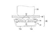
図5は、電磁調理器30の誘導加熱装置31に本発明を適用した場合である。電磁調理器30は、トッププレート32の上に置かれた鉄製の鍋等の被加熱体33をトッププレート32の下方に設けられた誘導加熱装置31によって誘導加熱するものである。
FIG. 5 shows a case where the present invention is applied to the
この実施の形態の誘導加熱装置31は、電線が“口”形状に巻回された加熱コイル11と、この加熱コイル11の加熱コイル面12とは反対側の面に放射状に取り付けられた複数の棒状のフェライト13と、加熱コイル11の外周を所定の間隔を開けて囲うように、かつ一方の端部が加熱コイル11の加熱コイル面12と略同一位置に配置された防磁リング15と、シールド材14とから構成されている。
The
シールド材14は、Si=0.1%,板厚0.6mmの鋼板に所定半径の円の円周位置から放射状に複数のスリット14aを設け、そのスリット14aを設けた鋼板を外径5cm,深さ2cmに深しぼり加工し、加工時の歪みを除去するために750℃×2hrの歪み取り焼鈍を行って成形している。図6はこのように成形したシールド材14を開口側から見た図である。図示のように、所定半径の円の中心がシールド材14の中心軸となっており、中心軸の所定位置から側面方向へ放射状の複数のスリット14aが中心軸に対して点対称となるように設けられている。
The
シールド材14は、開口側をトッププレート32側に向け、その先端部が防磁リング15の外縁に位置し、その防磁リング15の外縁からフェライト13を覆うように設置している。また、シールド材14のスリットの中心軸と加熱コイル11の中心軸とが略一致するように、シールド材14を設置している。すなわち、シールド材14を設置したときにスリット14aは加熱コイル11から発生する磁束の流れを妨げない方向に設けられている。
The
表1は、シールド材14を設置しない場合、スリット14aを設けていないシールド材(スリット14aを設けていない上述の鋼板に深しぼり等の同様な加工を施し成形したもの)を設置した場合、スリット14aを設けているシールド材14を設置した場合の3通りの場合で、電磁調理器30からの漏洩磁束の測定を行っている。また、スリット14aを設けていないシールド材を設置した場合及びスリット14aを設けているシールド材14を設置した場合の2通りでシールド材14の温度の測定を行っている。磁束の測定は、電磁調理器30のトッププレート32前面の縁から1cmの位置で行ったものであり、各シールド材の温度の測定は、熱電対温度計により、コイル中心軸に相当する位置で行っている。
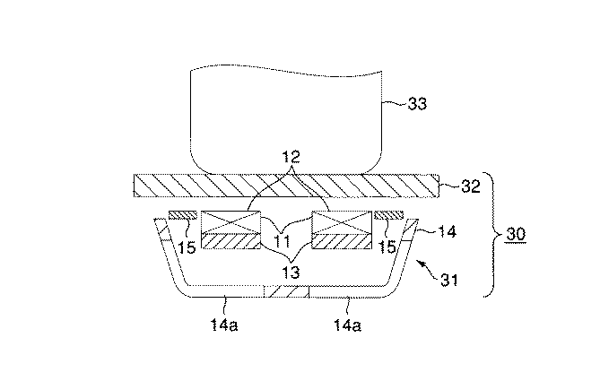
表1に示すように、シールド材を設置しない場合に比べ、各シールド材を設置した場合の方が漏洩磁束が低下している。また、シールド材を設置したときに、スリット14aを設けている場合とスリット14aを設けていない場合とで比較すると、スリット14aを設けている場合の方が漏洩磁束は若干大きいが、温度は大幅に低下していることがわかる。したがって、電磁調理器30の誘導加熱装置21においても前記実施の形態と同様な効果を奏することができる。
As shown in Table 1, the leakage magnetic flux is lower when each shield material is installed than when no shield material is installed. Further, when the shield material is installed, the leakage magnetic flux is slightly larger in the case where the
図7は、図5を参照して説明した電磁調理器30において、開口側の先端部が、防磁リング15よりトッププレート32側に、突出するようにシールド材14´を設置した場合である。このシールド材14´は上述のシールド材14とは、深しぼり加工を3.5cmにして0.5cm深く加工している点が異なっている。このシールド材14´を上述の場合と同様に設置している。したがって、シールド材14´の開口側先端は、深しぼりを0.5cm深くした分だけトッププレート32側に突出している。
FIG. 7 shows a case where the
表2は、このようにシールド材14´を設置した場合に表1と同様の測定を行った測定結果を示している。
表2に示すように、表1の測定結果と比較すると、シールド材14´の方が漏洩磁束を効果的に防止していることがわかる。また、スリット14aを設けていないシールド材14´は、加熱コイル11から発生する磁束による渦電流が流れるため発熱が大きく温度が大幅に上昇してしまうが、スリット14aを設けたシールド材14´はスリット14a間において局所的に渦電流が発生しても発熱はそれほど大きくならないため温度上昇が抑えられる。したがって、防磁リング15よりトッププレート側32に先端が突出しているシールド材14´により、発熱を抑制するとともに、さらに、効果的に漏洩磁束を低減することができる。
As shown in Table 2, when compared with the measurement results in Table 1, it can be seen that the
なお、この実施の形態では、シールド材14,14´を鍋状に加工して使用しているが、これに限るものではなく、被加熱体に対して閉磁路が形成できる形状であれば、板状、リング状の形状をしていても良い。
In this embodiment, the
なお、この発明は、上記実施の形態そのままに限定されるものではなく、実施段階ではその要旨を逸脱しない範囲で構成要素を変形して具体化でき、また上記実施形態に開示されている複数の構成要素の適宜な組み合わせにより種々の発明を変形できるものである。 Note that the present invention is not limited to the above-described embodiment as it is, and can be embodied by modifying constituent elements without departing from the scope of the invention in the implementation stage. Various inventions can be modified by appropriately combining the constituent elements.
1,2,21,31…誘導加熱装置
3,23,33…被加熱体
11…加熱コイル
12…加熱コイル面
13…フェライト
14,14´…シールド材
14a…スリット
15防磁リング
1, 2, 21, 31 ...
Claims (2)
前記加熱コイルを覆う強磁性体の金属からなるシールド材を有し、
前記シールド材は、前記加熱コイルにより発生する磁束の流れを妨げない方向に複数のスリットを設けたことを特徴とする誘導加熱装置。 In an induction heating apparatus for induction heating an object to be heated with a heating coil,
A shield material made of a ferromagnetic metal covering the heating coil;
The induction heating apparatus according to claim 1, wherein the shield material is provided with a plurality of slits in a direction that does not hinder the flow of magnetic flux generated by the heating coil.
前記加熱コイルの加熱面と反対面側に配置されたフェライトと、
前記加熱コイルの外周を所定の間隔を開けて囲うように配置された導電性金属からなる防磁リングと、
前記防磁リングの外縁から前記加熱コイル及び前記フェライトを覆う強磁性体の金属からなるシールド材とを有し、
前記シールド材は、前記加熱コイルにより発生する磁束の流れを妨げない方向に複数のスリットを設けたことを特徴とする誘導加熱装置。 In an induction heating apparatus for induction heating an object to be heated with a heating coil,
A ferrite disposed on the opposite side of the heating surface of the heating coil;
A magnetic shielding ring made of a conductive metal disposed so as to surround the outer periphery of the heating coil with a predetermined interval;
A shield member made of a ferromagnetic metal covering the heating coil and the ferrite from the outer edge of the magnetic shield ring;
The induction heating apparatus according to claim 1, wherein the shield material is provided with a plurality of slits in a direction that does not hinder the flow of magnetic flux generated by the heating coil.
Priority Applications (1)
| Application Number | Priority Date | Filing Date | Title |
|---|---|---|---|
| JP2003355299A JP2005122984A (en) | 2003-10-15 | 2003-10-15 | Induction heating device |
Applications Claiming Priority (1)
| Application Number | Priority Date | Filing Date | Title |
|---|---|---|---|
| JP2003355299A JP2005122984A (en) | 2003-10-15 | 2003-10-15 | Induction heating device |
Publications (1)
| Publication Number | Publication Date |
|---|---|
| JP2005122984A true JP2005122984A (en) | 2005-05-12 |
Family
ID=34612943
Family Applications (1)
| Application Number | Title | Priority Date | Filing Date |
|---|---|---|---|
| JP2003355299A Pending JP2005122984A (en) | 2003-10-15 | 2003-10-15 | Induction heating device |
Country Status (1)
| Country | Link |
|---|---|
| JP (1) | JP2005122984A (en) |
Cited By (5)
| Publication number | Priority date | Publication date | Assignee | Title |
|---|---|---|---|---|
| JP2009259836A (en) * | 2009-05-25 | 2009-11-05 | Hitachi Appliances Inc | Induction cooker |
| JP2009259835A (en) * | 2009-05-25 | 2009-11-05 | Hitachi Appliances Inc | Induction cooker |
| JP2009259608A (en) * | 2008-04-17 | 2009-11-05 | Hitachi Appliances Inc | Induction cooker |
| JP2013016341A (en) * | 2011-07-04 | 2013-01-24 | Toshiba Mitsubishi-Electric Industrial System Corp | Induction heating apparatus |
| JP2021052021A (en) * | 2021-01-06 | 2021-04-01 | 日立グローバルライフソリューションズ株式会社 | Electromagnetic induction heating device |
-
2003
- 2003-10-15 JP JP2003355299A patent/JP2005122984A/en active Pending
Cited By (6)
| Publication number | Priority date | Publication date | Assignee | Title |
|---|---|---|---|---|
| JP2009259608A (en) * | 2008-04-17 | 2009-11-05 | Hitachi Appliances Inc | Induction cooker |
| JP2009259836A (en) * | 2009-05-25 | 2009-11-05 | Hitachi Appliances Inc | Induction cooker |
| JP2009259835A (en) * | 2009-05-25 | 2009-11-05 | Hitachi Appliances Inc | Induction cooker |
| JP2013016341A (en) * | 2011-07-04 | 2013-01-24 | Toshiba Mitsubishi-Electric Industrial System Corp | Induction heating apparatus |
| JP2021052021A (en) * | 2021-01-06 | 2021-04-01 | 日立グローバルライフソリューションズ株式会社 | Electromagnetic induction heating device |
| JP7015402B2 (en) | 2021-01-06 | 2022-02-02 | 日立グローバルライフソリューションズ株式会社 | Electromagnetic induction heating device |
Similar Documents
| Publication | Publication Date | Title |
|---|---|---|
| JP5114671B2 (en) | Induction heating apparatus and induction heating method for metal plate | |
| EP2236005B1 (en) | Controlled electric induction heating of an electrically conductive workpiece in a solenoidal coil with flux compensators | |
| JP6323564B2 (en) | Induction heating device for metal strip | |
| JP4786365B2 (en) | Induction heating apparatus and induction heating method for metal plate | |
| JP5042909B2 (en) | Induction heating apparatus and induction heating method for metal plate | |
| JP4069002B2 (en) | Metal strip heating device with excellent temperature uniformity in the plate width direction | |
| US10005116B2 (en) | High frequency induction heating apparatus and processing apparatus | |
| JP2008266727A (en) | Induction heating facility | |
| JP2005122984A (en) | Induction heating device | |
| KR101558088B1 (en) | Induction heating apparatus | |
| JP3869711B2 (en) | Metal strip heating device with excellent temperature uniformity in the plate width direction | |
| JP4833740B2 (en) | Metal strip heating device with excellent temperature uniformity in the plate width direction | |
| JP2005122983A (en) | Induction heating device | |
| JP2005122986A (en) | Induction heating device | |
| JP4035122B2 (en) | Steel strip heating method with excellent temperature uniformity in the width direction | |
| JP2000015319A (en) | Induction heating device for side part of metal plate | |
| JP7124515B2 (en) | Induction heating equipment for metal strips | |
| JP4303607B2 (en) | Induction heating method for steel sheet | |
| JP6812999B2 (en) | Induction heating device for metal strips, manufacturing method for metal strips, and manufacturing method for alloyed hot-dip galvanized steel sheets | |
| JP2006207004A (en) | Method for high frequency heating | |
| JP4890278B2 (en) | Metal plate induction heating device | |
| JP2018048388A (en) | Alloying method of molten zinc plated layer | |
| JP2018048389A (en) | Continuous molten zinc plating apparatus of steel plate, and production method of alloyed steel plate galvanized with molten zinc | |
| JP3168403U (en) | Overheating suppression induction heating device | |
| JP5015345B2 (en) | Induction heating apparatus and induction heating method for metal plate |