JP2004526934A - Internal heat exchanger accumulator - Google Patents
Internal heat exchanger accumulator Download PDFInfo
- Publication number
- JP2004526934A JP2004526934A JP2002591735A JP2002591735A JP2004526934A JP 2004526934 A JP2004526934 A JP 2004526934A JP 2002591735 A JP2002591735 A JP 2002591735A JP 2002591735 A JP2002591735 A JP 2002591735A JP 2004526934 A JP2004526934 A JP 2004526934A
- Authority
- JP
- Japan
- Prior art keywords
- inner liner
- accumulator
- refrigerant
- passage
- outer housing
- Prior art date
- Legal status (The legal status is an assumption and is not a legal conclusion. Google has not performed a legal analysis and makes no representation as to the accuracy of the status listed.)
- Pending
Links
Images


Classifications
-
- F—MECHANICAL ENGINEERING; LIGHTING; HEATING; WEAPONS; BLASTING
- F28—HEAT EXCHANGE IN GENERAL
- F28D—HEAT-EXCHANGE APPARATUS, NOT PROVIDED FOR IN ANOTHER SUBCLASS, IN WHICH THE HEAT-EXCHANGE MEDIA DO NOT COME INTO DIRECT CONTACT
- F28D7/00—Heat-exchange apparatus having stationary tubular conduit assemblies for both heat-exchange media, the media being in contact with different sides of a conduit wall
- F28D7/02—Heat-exchange apparatus having stationary tubular conduit assemblies for both heat-exchange media, the media being in contact with different sides of a conduit wall the conduits being helically coiled
- F28D7/024—Heat-exchange apparatus having stationary tubular conduit assemblies for both heat-exchange media, the media being in contact with different sides of a conduit wall the conduits being helically coiled the conduits of only one medium being helically coiled tubes, the coils having a cylindrical configuration
-
- F—MECHANICAL ENGINEERING; LIGHTING; HEATING; WEAPONS; BLASTING
- F25—REFRIGERATION OR COOLING; COMBINED HEATING AND REFRIGERATION SYSTEMS; HEAT PUMP SYSTEMS; MANUFACTURE OR STORAGE OF ICE; LIQUEFACTION SOLIDIFICATION OF GASES
- F25B—REFRIGERATION MACHINES, PLANTS OR SYSTEMS; COMBINED HEATING AND REFRIGERATION SYSTEMS; HEAT PUMP SYSTEMS
- F25B40/00—Subcoolers, desuperheaters or superheaters
-
- F—MECHANICAL ENGINEERING; LIGHTING; HEATING; WEAPONS; BLASTING
- F25—REFRIGERATION OR COOLING; COMBINED HEATING AND REFRIGERATION SYSTEMS; HEAT PUMP SYSTEMS; MANUFACTURE OR STORAGE OF ICE; LIQUEFACTION SOLIDIFICATION OF GASES
- F25B—REFRIGERATION MACHINES, PLANTS OR SYSTEMS; COMBINED HEATING AND REFRIGERATION SYSTEMS; HEAT PUMP SYSTEMS
- F25B43/00—Arrangements for separating or purifying gases or liquids; Arrangements for vaporising the residuum of liquid refrigerant, e.g. by heat
- F25B43/006—Accumulators
-
- F—MECHANICAL ENGINEERING; LIGHTING; HEATING; WEAPONS; BLASTING
- F25—REFRIGERATION OR COOLING; COMBINED HEATING AND REFRIGERATION SYSTEMS; HEAT PUMP SYSTEMS; MANUFACTURE OR STORAGE OF ICE; LIQUEFACTION SOLIDIFICATION OF GASES
- F25B—REFRIGERATION MACHINES, PLANTS OR SYSTEMS; COMBINED HEATING AND REFRIGERATION SYSTEMS; HEAT PUMP SYSTEMS
- F25B2309/00—Gas cycle refrigeration machines
- F25B2309/06—Compression machines, plants or systems characterised by the refrigerant being carbon dioxide
- F25B2309/061—Compression machines, plants or systems characterised by the refrigerant being carbon dioxide with cycle highest pressure above the supercritical pressure
-
- F—MECHANICAL ENGINEERING; LIGHTING; HEATING; WEAPONS; BLASTING
- F25—REFRIGERATION OR COOLING; COMBINED HEATING AND REFRIGERATION SYSTEMS; HEAT PUMP SYSTEMS; MANUFACTURE OR STORAGE OF ICE; LIQUEFACTION SOLIDIFICATION OF GASES
- F25B—REFRIGERATION MACHINES, PLANTS OR SYSTEMS; COMBINED HEATING AND REFRIGERATION SYSTEMS; HEAT PUMP SYSTEMS
- F25B2400/00—General features or devices for refrigeration machines, plants or systems, combined heating and refrigeration systems or heat-pump systems, i.e. not limited to a particular subgroup of F25B
- F25B2400/03—Suction accumulators with deflectors
-
- F—MECHANICAL ENGINEERING; LIGHTING; HEATING; WEAPONS; BLASTING
- F25—REFRIGERATION OR COOLING; COMBINED HEATING AND REFRIGERATION SYSTEMS; HEAT PUMP SYSTEMS; MANUFACTURE OR STORAGE OF ICE; LIQUEFACTION SOLIDIFICATION OF GASES
- F25B—REFRIGERATION MACHINES, PLANTS OR SYSTEMS; COMBINED HEATING AND REFRIGERATION SYSTEMS; HEAT PUMP SYSTEMS
- F25B2400/00—General features or devices for refrigeration machines, plants or systems, combined heating and refrigeration systems or heat-pump systems, i.e. not limited to a particular subgroup of F25B
- F25B2400/05—Compression system with heat exchange between particular parts of the system
- F25B2400/051—Compression system with heat exchange between particular parts of the system between the accumulator and another part of the cycle
-
- Y—GENERAL TAGGING OF NEW TECHNOLOGICAL DEVELOPMENTS; GENERAL TAGGING OF CROSS-SECTIONAL TECHNOLOGIES SPANNING OVER SEVERAL SECTIONS OF THE IPC; TECHNICAL SUBJECTS COVERED BY FORMER USPC CROSS-REFERENCE ART COLLECTIONS [XRACs] AND DIGESTS
- Y10—TECHNICAL SUBJECTS COVERED BY FORMER USPC
- Y10T—TECHNICAL SUBJECTS COVERED BY FORMER US CLASSIFICATION
- Y10T29/00—Metal working
- Y10T29/49—Method of mechanical manufacture
- Y10T29/49394—Accumulator making
Abstract
空気調和(冷凍またはヒートポンプ)システム用アキュムレータ(10、110、310)は、内側ライナ(36、136、236、336)を同軸に包囲する外側ハウジング(22、122、222)を具体化している。入口(28、128、228、328)は、内側ライナ(36、136、236、336)によって形成されている内部容積内に冷媒を誘導する。該容積内には液状冷媒および圧縮機オイルが含有され、外側ハウジング(22、122、222)の壁から絶縁されている。熱交換器(20、120、220)は、外側ハウジング(22、122、222)と内側ライナ(36、136、236、336)との間の環状空間(40、140、240、340)内に配置されており、膨張装置に送給する前に凝縮物の流れを循環させる。このようにして、凝縮物は冷却され、同時に、アキュムレータ(10、110、310)を通って出る冷媒は蒸発させられる。An accumulator (10, 110, 310) for an air conditioning (refrigeration or heat pump) system embodies an outer housing (22, 122, 222) coaxially surrounding an inner liner (36, 136, 236, 336). Inlets (28, 128, 228, 328) direct refrigerant into the interior volume formed by the inner liners (36, 136, 236, 336). The volume contains liquid refrigerant and compressor oil and is insulated from the walls of the outer housing (22, 122, 222). The heat exchangers (20, 120, 220) are in an annular space (40, 140, 240, 340) between the outer housing (22, 122, 222) and the inner liner (36, 136, 236, 336). And circulates the condensate stream prior to delivery to the expansion device. In this way, the condensate is cooled, while the refrigerant exiting through the accumulators (10, 110, 310) is evaporated.
Description
【技術分野】
【0001】
本発明は、空気調和即ちヒートポンプシステムに使用されるアキュムレータの改良、詳しくは、自動車の空気調和システムでの使用に適したサクションアキュムレータに関する。
【背景技術】
【0002】
閉ループ冷凍/ヒートポンプシステムは、気体冷媒を比較的低い圧力で引き込み、高温冷媒を比較的高い圧力で吐出するように意図されている圧縮機を従来採用している。一般に、高温冷媒は、凝縮器において冷却される際に、凝縮されて液体になる。小さなオリフィスまたは弁がシステムを高圧側と低圧側に分けている。高圧側の冷媒は、オリフィスまたは弁を通過し、蒸発器において熱を吸収する際に液体からガスに変わる。低熱負荷時に、全部の液体を蒸発させることは望ましくなく、また、それは不可能である。しかし、(“フラッディング”として知られる)圧縮機への進入を行う液状冷媒は、システム効率の損失を生じ、圧縮機への損傷を生じ得る。それゆえ、余剰な液体を分離し蓄えるために蒸発器と圧縮機との間にアキュムレータを備えることが標準的な実務となっている。自動車の空気調和システム用アキュムレータは、一般に、一体に溶接された金属缶であり、しばしば、該アキュムレータには、切換えおよび/または充填口用に取付具が取り付けられている。1つ以上の入口管および出口管が頂部、側部、或いは時として底部の内部を通っている。又は、該管は、上記の目的で設けられた取付具に取り付けられている。一般的なアキュムレータ内へ流れ込む冷媒は、液体が意図せずに出口から流出する可能性を低減する目的で設けられたそらせ板またはバッフルに衝突する。
【0003】
ある先行技術は、液体のキャリオーバを低減するための方法として流入する液体の乱流を低減する技術に関連している(米国特許第5184480号)。また、他には、主としてアキュムレータにおける圧力降下(重大なシステム性能パラメータ)を減じるために、内側貯槽と出口通路との結合に特に関連している技術がある(米国特許第5660068号、第5179844号および第4627247号)。
【0004】
先行技術の別の特徴としては、アキュムレータにおける乾燥剤の装備である。ある冷凍システム、特にあまり現代的でないシステムは、他のものよりも水分の進入および損傷を受けやすい。多くのシステムにとってあらゆる水分を除去することが必要であり、アキュムレータは乾燥剤を収容するために便利な場所である。初期の多くの設計にみられる特徴としては、乾燥カートリッジ等があったが(米国特許第4509340号、第4633679号、第4768355号および第4331001号)、現代は、乾燥剤ビーズで満たされ、(J字形出口管のような)アキュムレータの内部の特徴部に固定された適切な形状の布袋が典型例となっており、該布袋のビーズは液状冷媒と接触する。
【0005】
先行技術の代表的な特徴としては、他に、熱特性を修正するために、アキュムレータの外周に配置された絶縁材の使用である(米国特許第5701795号)。これは、費用が嵩み、フラッディングを減じる必要がある場合にしか使用されない。
【0006】
典型的なアキュムレータにおける共通の特徴の一つとして、該アキュムレータが圧縮機オイルを戻して循環させるために何らかの技術を採用していることである。圧縮機オイルは、一般に、冷媒とともにシステム全体を循環しているが、アキュムレータの貯槽に溜まる傾向がある。オイルを戻して循環させるための典型的な方法としては、アキュムレータを出る前に貯槽内に低く浸る冷媒ガスの出口管を利用することである。低い地点にある出口管の小さい穴によって、液体はガス流と同伴して圧縮機へ向かう。この液体の一部が冷媒となることは避けられない。圧縮機へ戻るこの液状冷媒によって、システム効率が低減する。
【0007】
通常の動作において、圧縮機に戻るガスは、凝縮器からの液体に比べてかなり冷たい。圧縮機に戻るガスが膨張装置に到達する前に凝縮物をさらに冷却するために使用されるのであれば、冷凍サイクルの冷却能力および効率が上がることは周知である(米国特許第5075967号)。(超臨界用途において、液体は、膨張装置の後に低圧で存在しているにすぎない。厳密に言えば、凝縮器は“ガス冷却器”である。しかし、我々、本願発明者は、本発明の原理が超臨界冷凍システムにも同様に適用されるものと理解して、“凝縮器”及び“凝縮物”という用語を使用する。)高圧側から低圧側へ熱を伝達するために使用される熱交換器は、「吸込み線路熱交換器」(SLHX)または「内部熱交換器」(IHX)と称する。(システムと環境との間で熱を交換する凝縮器および蒸発器に対して、システムにとって「内部」である。)オイルピックアップ穴を備えるアキュムレータを使用するシステム、IHXにおいて、その効果は、ピックアップ穴によって同伴される液状冷媒が蒸発して凝縮物を冷却する際に、向上される。先行技術は、従来の熱交換器がIHXとして使用され得ると認識しているが(米国特許第5562157号、第5609036号、第5687419号)、一般に移動体への用途の場合、大型な蒸発器のための余地がなく、他の構成部品の装備も経済的に容認できない。IHXとアキュムレータとを組合せることにより、漸増的に大きくなるにすぎないスペースおよび重量を要する費用の面で効果的な解決策を提供することができる。
【0008】
先行技術のいくつかの例としては、高温凝縮物を含んでいる管のコイルまたは一部が熱交換のためにアキュムレータの貯槽部内に配置されることを提案している(米国特許第5075967号、第5245833号、第5622055号)。しかし、そのような設計は最適ではない。高温凝縮物はアキュムレータ貯槽の低圧液体を沸騰させ、貯槽の目的を無効にし、ガスでシステムに負荷をかけることによってシステム効率を低減させる。高温凝縮物のコイルが主貯槽の外部に配設されることを提案する先行技術が存在するが(米国特許第6298687号)、当該技術は貯槽との熱交換を高めようとしている。我々、発明者等の研究は、貯槽への熱伝達が低減されなければならないことを明白に示している。さらに、先行技術は、他の方法ではアキュムレータとして良好に働かないIHXアキュムレータを示している。例えば、米国特許第6298687号は、システムが停止した時に貯槽から圧縮機に排出されるように構成されたオイルピックアップ穴を示している。ガスの流入の際の乱流を低減したり、貯槽内の液体がガスの出口に逃げることを防ぐ技術は、存在しない。また、先行技術の多くはその組立が難しい。米国特許第6298687号はアキュムレータの両側端部にある高圧線路の入口および出口を示しているが、それは容易に量産することはできない。製造が容易でアキュムレータ機能を保持する単純で費用およびスペースの点で効果的な構成を有し、高圧線路から貯槽への熱伝達が制御されて、アキュムレータと組み合わされた内部熱交換器が求められている。
【発明の開示】
【課題を解決するための手段】
【0009】
2001年1月25日に出願された本願発明人等による国際出願番号PCT/CA01/00083において、本願発明人等は、特に車両の空気調和システムにおける使用に適する多くの重要な改良点を有している先進的な設計が施されているサクションアキュムレータを開示している。
【0010】
本発明は、更に改良されたサクションアキュムレータを提供している。
【0011】
詳しくは、本発明は、空気調和またはヒートポンプシステムに使用されるアキュムレータを提供する。該アキュムレータは、頂部と入口開口と出口開口と周囲側壁と基部とから成る気密封止された外側ハウジングと、前記外側ハウジング内に配置された内側ライナと、熱交換管と、伝達通路と、から成り、前記内側ライナは、前記入口開口を通じて送給された冷媒を収容して前記冷媒を液体および蒸気に分離するための容器を形成する基部および周壁を有しており、前記内側ライナは、前記外側ハウジングの周壁から離間して、前記周壁とともに環状通路を画成しており、前記熱交換管は前記環状通路に配置され、前記管は、前記システム内において、高圧冷媒から低圧冷媒へ制御された速度で熱伝達を行うように設計および構成されており、前記管は、前記外側ハウジングの外側で延びている入口端部および出口端部を有しており、断熱材料は、前記熱交換管と内部容器とを分離して前記内側容器内の冷媒への熱伝達を抑止し、前記伝達通路は、前記環状通路の上端部および下端部にそれぞれ設けられており、前記伝達通路の一方は、前記環状通路と前記内側ライナの内部とを連通させる入口から成り、前記伝達通路の他方は、前記環状通路と前記ハウジングの外部とを前記出口開口を通じて連通させる出口から成り、前記内側ライナから引かれた蒸発した冷媒は、前記一方の伝達通路を通じて前記環状通路に入る一方で、液状冷媒は前記環状通路に入ることを防止され、前記蒸発した冷媒は前記環状通路を通り、前記熱交換管に沿って前記他方の伝達通路へ流れ、前記蒸発した冷媒は前記他方の伝達通路から前記出口開口を介して前記アキュムレータを出る。
【0012】
熱交換管は、システムの高圧側、すなわち圧縮機の出口、凝縮器および膨張弁と、システムの低圧側との間での熱交換のための機構をアキュムレータに組み込む方法を提供している。そうしたものとして、管は、表面積を増大させるように設計されたもの等の各種の向上策を実施することができる。さらに、好ましい実施形態としては単一の連続する熱交換管であるが、他の構成も可能である。効果的な熱交換は、アキュムレータを出て圧縮機の入口に送給される気体冷媒が熱交換管を伝って移動する一方で、高圧側からの比較的高温の冷媒を熱交換管を介して循環させることによって、実現する。この両者によって、膨張に先立って液状冷媒が予冷され、システム冷却能力が増大し、また、この両者は、圧縮機に到達する冷媒ガス流が液状冷媒を含まないことを保証するのに役立つ。効果的な熱交換は、吸気線路の圧力損失の増加が殆どなく、また、アキュムレータ機能に妥協することのない状態で実現される。本願に開示される熱交換器には、付加的な部品がほとんどない。また、本願に開示される熱交換器は、より効果的であり、好適な実施形態においては、先行技術で周知のようなアキュムレータと内部熱交換器とを組合せたものよりも製造が容易であり且つ安価である。
【0013】
好ましくは、熱交換管は、アキュムレータの外側ハウジングと内側ライナとの間の環状通路に、らせん状コイルの形状で配置され、それによって、該環状通路においてコイルの長さに沿って冷媒蒸気のらせん状流路を画成する。熱交換管の外径は、外側ハウジングと内側ライナの間との環状通路の幅と一致しており、冷媒ガス流のほとんど全部がらせん状経路の全長を進行するような封止を提供する。外側ハウジングの同一端部に入口および出口を配するために単一のらせん状コイルを戻り管路とともに使用する場合には、らせん状経路を避けて迂回するように形成された短い経路を冷媒ガスが使用しないようにしなければならない。二重らせんコイルの使用はそうした懸念を排除する。
【0014】
内側ライナは、好ましくは、熱伝導性の低いプラスチック材料で製作され、もって、その内部に含有されている液状冷媒がコイルおよび外側ハウジングの熱から絶縁される。
【発明を実施するための最良の形態】
【0015】
図1の回路図は、冷却装置またはヒートポンプとして使用可能な閉回路空気調和システムを概略的に示している。冷媒流体は、液状でアキュムレータ10内に蓄えられており、該アキュムレータ10から圧縮機12の入口にガスの形状で引き込まれる。圧縮機は、高温高圧の冷媒ガスを凝縮器14に送給し、該凝縮器においてガスは冷却され、一般的にはガスの一部は液状に変換される。(依然として高圧下にある)凝縮器からの冷媒流体は、膨張弁16を経て低圧に膨張し、それによって温度の急激な低下を受けて、低圧で低温の流体は、蒸発器18において加熱され、該蒸発器18から液体およびガスの混合流としてアキュムレータ10に戻される。システムの負荷に応じて、冷媒流体は、多少、凝縮および蒸発せしめられ、システムがその時要求した量を上回る量の冷媒はアキュムレータ10に液状で蓄えられる。以上で説明された図1の回路は、従来の回路である。
【0016】
図1のシステムは、凝縮器から送給された一部冷却されているが依然温暖な冷媒流体をアキュムレータ内の熱交換コイル20に通すことによって変更される。以下でさらに詳しく説明するが、熱交換コイル20は、アキュムレータ10の冷媒液体と接触しておらず、むしろ圧縮機12によってアキュムレータから引き出される冷媒ガスと接触するように配置されており、その目的は高圧冷媒を予冷すること、及び、圧縮機に送給された冷媒の完全な蒸発を保証することである。
【0017】
アキュムレータ10の構造は、図2乃至図6においてより明確に示されており、円筒形の外側容器22から成る。該外側容器22の下端部は底蓋24によって閉じられており、外側容器22の上端部は気密封止した状態で円板形状のヘッド取付具26に取り付けられされている。該ヘッド取り付け具26は、以下の連結部を収容する複数の口を備えている。該連結部は、蒸発器から冷媒流体を送給する入口管28と、冷媒ガスがアキュムレータから圧縮機12へ向かう際に通過する出口管30と、凝縮器14から膨張弁16へ通過する冷媒流体を送給する熱交換コイル20と連通している出口連結部34及び入口連結部32である。
【0018】
外側容器内には、同軸に配置された円筒形内側ライナ36があり、該内側ライナ36の上端部はヘッド取付具26の下面に密に接した状態で配置されているが、該ヘッド取付具26と協力して複数の伝達通路38を画成している。複数ある伝達通路38のうちの1つが図2に示されている。一連の伝達通路38は、ヘッド取付具の周辺部の周りに間隔をおいて配設されている。通路38間のリブは内側ライナ36の上端部に載っている。図3に見られるように、内側ライナ36と外側容器22との間における頂部から底部まで延びている環状通路40が存在する。この通路の延長部分は、突出リブ42によって底蓋24から離間されている内側ライナ36の下面で径方向内方に延びている。アキュムレータの下端で環状通路40と連通する中心管44は、アキュムレータの内部の中心において上方へ延びており、出口管30と接続されている。中心管44及び出口管30は、両者ともヘッド取付具26に気密封止されている。
【0019】
熱交換器コイル20用の入口連結部32は、アキュムレータの底部付近まで垂直方向に延びており、図2に最適に示されるように、該コイルは、底部近くから、環状空間40内をらせん状に上方に延びている。コイルの上端は垂直に向いており、出口連結部34と一体となっている。連結部32、34が垂直に配置されるようにするために、内側ライナの外表面には軸方向に延在する凹部46、48(図3参照)が形成されている。連結部32、34は、これらの凹部に収容されており、もって、内側容器36の外表面によって画成される円筒形包絡面を越えて突出することはない。内側容器36並びに入口連結部及び出口連結部32、34は、密着外側ライナ50によって包囲されている。該外側ライナ50は環状通路40の内側円筒形表面を画成している。この環状通路は、熱交換器コイル20を形成する管の外径と厳密に対応する一定の径方向の幅を有しており、もって、該熱交換コイル20を形成する管は外側ライナ50と外側容器22との間に適宜に嵌合し、この嵌合によって、コイルとこれらの構成部品との間を封止(シール)して、冷媒ガスが巻回されたコイルの間に画成される延長流路を避けて迂回することが防止される。図2、図5および図6から明白であるように、外側ライナ50は、内側ライナ36の上端部から該内側ライナ36の長さの主要部分にわたって延び、コイル20の下端位置の若干上方で終結している。
【0020】
アキュムレータの動作について説明する。低圧の冷媒流体は、蒸発器から入口管28を経て内側ライナ36内に送給される。該内側ライナにおいて、冷媒流体は分離し、その液体部分は、該冷媒と同伴している少量のオイルとともに内側ライナの下端部に集まる。該オイルは、一般に圧縮機の潤滑のために含まれている。
【0021】
加熱または冷却の負荷の需要によって決定されるが、圧縮機12は気体冷媒をアキュムレータから引出すように駆動される。圧縮機による吸込み動作は、中心管44、環状空間40および伝達通路38を介して内側ライナ36の内部に及ぶ。従って、この領域からの冷媒ガスは、伝達通路38を経て環状通路40に引き込まれる。圧縮機の吸込みの需要に従って、アキュムレータにおいて生じた低圧は、多少の液状冷媒を蒸発させる。しかし、冷媒ガスは環状通路の下端部に直接通過できない。むしろ、該冷媒ガスは、コイル20によって案内され、巻回されたコイルの間のらせん状の経路を取りながら、該コイルと熱交換の関係を保ちつつ下降し、やがてアキュムレータの下端部に到達する。冷媒ガスは、該下端部から突出リブ42間を径方向内方に向かって通ることができる。この下降している間に、冷媒ガスはコイル20から熱を奪うので、圧縮機に送給された冷媒が完全に蒸発することが保証される。この動作は、内側ライナが熱伝導性の低いプラスチックで形成されているという事実と、内側ライナに類似する断熱材料で形成される外側ライナ50の存在と、によって、内側ライナ36の下端部内にて液状冷媒を過度に加熱することなく実現される。内側ライナ36および外側ライナ50の材料の伝導率はわずか約10W/m・Kしかない。通路40と凹部46、48とが外側ライナ50によって効果的に遮断されているので、通路40の冷媒ガスは、内側ライナに形成された凹部46、48を通って通路の底部に直接移動できないことに留意されたい。
【0022】
発明者等による前述の国際出願に記載されているように、内側ライナ36は、一般に、冷媒流体に存在し得るあらゆる水分を抽出するために乾燥剤塊(図示せず)を含んでいる。さらに当該出願に記載されているように、内側容器36の下端部はフィルタおよびブリード穴を備えることができる。該下端部に集まっているオイルは、該フィルタ及びブリード穴を通じて、冷媒ガスが内側ライナ36の下面を横断するように移動する際に、該冷媒ガスに引き込まれ得る。
【0023】
通路40を通ってアキュムレータを出て行く冷媒ガスは、コイル20を通って移動する温暖な冷媒流体とは逆流の関係で流れる。従って、冷媒ガスは内側ライナの下端部の下を通って中心管44内に流れ込む直前にコイルの最も温暖な領域を通過することがわかる。この構成は熱伝達の効果を向上させる。
【0024】
アキュムレータにおいて、特に自動車の空気調和システムに使用されるアキュムレータにおいては、入口管20を介してアキュムレータに進入する液状冷媒が出口通路に直接向かうことを防止するためのバッフル(baffle)手段を設けることが慣例であり、この目的のために先行技術で周知の各種手段が提供されている。図2乃至図6に示されたアキュムレータの設計では、ヘッド取付具26の下面の形状がバッフル効果を与えている。ヘッド取付具26の下面にある入口管28の内側端は、凹状溝によって包囲されている。該凹状溝は、管28の縁部に付着する液状冷媒がヘッド取付具26の下表面を横断するように移動する傾向を防止する。更に、内側ライナ36の上端の周から離間している伝達通路38は、実際には、ヘッド取付具26の下表面の位置から若干上方にずらされている。更に、これらのラビリンス伝達通路38の細やかな形状は、熱交換通路に流れ込むガスに乱流を生じさせてコイル20との熱交換を高めるように、構成されることも可能である。
【0025】
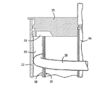
図2乃至図6のアキュムレータは、ヘッド取付具26を通って延びている流体連結部の全てを示しているが、例えば図7に示すように他の構成も可能であり、図7のアキュムレータ110においては、蒸発器から冷媒を送給する入口管128及び冷媒ガスをアキュムレータから圧縮機に送給する出口管130のみがヘッド取付具126に配置されている。この実施形態では、熱交換器コイル120は、上述の実施例と同様、外側容器122と内側ライナ136との間の通路140に密着して嵌合された状態でらせん状に延在している。しかしこの実施形態では、コイル120は、その入口連結部132および出口連結部134の両者がアキュムレータの底蓋124を貫通するように、二重らせんになっている。従って、交互に巻かれているコイル120において、冷媒流体は、互いに反対方向に流れる。従って、この実施形態では、内側ライナ136の外表面は完全に円筒形となり、それゆえ、図2乃至図6において参照番号50で示されたような外側ライナを必要としない。図7の実施形態は、また、図7Aにより詳細に図示されているように、アキュムレータにそらせ板を組み入れる方法も示している。そらせ板150は、サドルの形状をしており、直径頂部150.1を有している。該直径頂部から、下方に傾斜した2つの半円形側面150.2が延びている。頂部の中心円形穴150.3は、内側ライナ136の中心管144の上端部を包囲しており、ヘッド取付具126の下面の短い管状ソケット150.4の周をシールする大きさである。反らせ板150は、内側ライナ136の内径に対応する直径を有する板状の金属製円板から形成できる。従って、そらせ板150は、頂部150.1の両端部にて内側ライナに当接しており、また内側ライナに隣接する領域において、側面150.2の下側部は三日月形通路150.5によってライナ136の内壁から分離されている。入口管128から離間しているそらせ板150の下面において、伝達通路138は内側ライナ136の内部と環状通路140とを連通させている。この通路138の上側は、広角な逆V字形となっており、反らせ板150の周縁部によって塞がれているので、反らせ板の上側から通路138内に連通することはない。動作中、入口管128を介してアキュムレータに送給される蒸発器からの冷媒ガスおよび液体は、頂部150.1に衝突してソケット150.4の一面に移動し、開口150.5を介して貯槽部に流入する。アキュムレータの貯槽部から出た冷媒ガスは、伝達開口138を介して引かれ、環状通路140によって設けられた熱交換部に入り、その後、中心管144および出口管130を通ってアキュムレータを出る。
【0026】
本発明のさらなる別の実施例の構成が図8に示されている。ここでは、入口管228は、外側容器222の上端部内の中心に開口している。これにより、外側容器の頂部表面は一体型の表面となる。しかしこの実施形態では、円筒形内側ライナ236は上方に延びている中心管244を有する。該中心管244は、小さなサイホン防止穴245を除き、上端が閉鎖されている。アキュムレータから圧縮機に送給されるガスの出口は底蓋224に形成されており、この出口230は、管244の閉鎖している上端付近で終端している鉛直方向に延びている管231と連通している。この実施形態において、熱交換管220は、前と同様、外側容器222と内側ライナ236との間の環状通路240に適宜に配置されている。図8に示すように、熱交換コイル220の入口232および出口234は、外側容器222の側壁を貫通しているが、他の構成も可能である。
【0027】
図9は本発明のさらなる別の実施例を示している。この場合、蒸発器からの冷媒ガスおよび液体は、アキュムレータ310の側壁の入口管328を通じて入る。液体は、(任意の)そらせ板337に衝突し、貯槽部に流入する。圧縮機からの力を受けて、ガスは、ライナ336の立上り管331の開口端に流入する。その後、ガスは、ライナと底蓋324との間のスペースを通り下方に流れ、熱交換器通路340を通って上方に流れる。ガスは熱交換器コイルの頂部にあるキャビティ338に集まり、側壁の取付具330を通じてアキュムレータを出る。熱交換器通路を避けて迂回する流体経路が貯槽内に形成されることを防止するように、入口管が貯槽部の壁に密着した状態で取り付けられることが重要である。
【0028】
本発明の範囲内において、設計される空気調和システムの特定の要求を満たすために、寸法、形状、大きさ、向きおよび材料に関して相当の変更を行うことは可能である。同様に、ヘッド取付具、外側容器といった外部構造、入口および出口ポートの位置および構成は所望通りに変更することができ、乾燥剤容器、オイルブリード調節器およびフィルタの形式および構成の変更についても同様である。
【0029】
便宜上、本発明の一定の特徴は別個の実施形態において説明したが、これらの特徴は1つの実施例で組合せて提供してもよいことを理解されたい。さらに、簡潔のために1つの実施例において説明された本発明の各種特徴は、また、他の実施例において、別個に或いは部分的に適宜に組合せて提供してもよい。
【0030】
さらに、本発明の特定の実施例を以上で図示及び説明したが、各種変更が当業者には容易に行い得ることは認識できよう。従って、添付の特許請求の範囲は、本発明の変形例及び等価物の全てを包括するものと解釈すべきである。
【図面の簡単な説明】
【0031】
【図1】本発明の好適な実施例におけるアキュムレータを具現化している(冷却または加熱に使用可能な)空気調和システムの回路の概略図である。
【図2】図1に示した空気調和システムのアキュムレータの概略的な斜視図であり、一部の断面が示されている。
【図3】図2のIII−III線における拡大断面図である。
【図4】分離されたアキュムレータの部品を示す図2に対応する分解図である。
【図5】冷媒ガスの流れを示す図2の一部の拡大図である。
【図6】冷媒ガスの流れを示す図2の一部の拡大図である。
【図7】本発明の別実施例におけるアキュムレータの縦断面を概略的に示す図である。
【図7A】図7のアキュムレータの上部部分を概略的に示している破断斜視図である。
【図8】本発明の更なる別の実施例におけるアキュムレータの構成の縦断面図である。
【図9】本発明の更なる別の実施例におけるアキュムレータの構成の縦断面図である。
【符号の説明】
【0032】
10 アキュムレータ
12 圧縮機
14 凝縮器
16 膨張弁
18 蒸発器
20 熱交換コイル
22 外容器
24 底蓋
26 ヘッド取付具
28 入口管
30 出口管
32、34 連結部
36 内側ライナ
38 伝達通路
40 環状通路
42 突出リブ
44 中心管
46、48 凹部
50 外側ライナ
110 アキュムレータ
120 熱交換器コイル
122 外容器
124 底蓋
126 ヘッド取付具
128 入口管
130 出口管
136 内側ライナ
138 伝達通路
140 環状通路
144 中心管
150 反らせ板
150.1 直径稜部
150.1 稜部
150.2 側面
150.2 半円形側面
150.3 中心丸穴
150.4 ソケット
150.5 三日月形通路
220 熱交換コイル
222 外容器
224 底蓋
228 入口管
232 入口
234 出口
236 内側ライナ
240 環状通路
244 中心管
245 サイホン防止穴
310 アキュムレータ
324 底蓋
328 入口管
330 取付具
331 立上り管
336 ライナ
338 空洞
340 反らせ板【Technical field】
[0001]
The present invention relates to improvements in accumulators used in air conditioning or heat pump systems, and more particularly, to suction accumulators suitable for use in automotive air conditioning systems.
[Background Art]
[0002]
Closed loop refrigeration / heat pump systems conventionally employ a compressor that is intended to draw a gaseous refrigerant at a relatively low pressure and discharge a hot refrigerant at a relatively high pressure. Generally, the hot refrigerant is condensed into a liquid when cooled in the condenser. A small orifice or valve separates the system into a high pressure side and a low pressure side. The high pressure side refrigerant passes through an orifice or valve and changes from liquid to gas as it absorbs heat in the evaporator. At low heat loads, it is undesirable and impossible to evaporate all the liquid. However, liquid refrigerant entering the compressor (known as "flooding") can cause loss of system efficiency and damage to the compressor. It is therefore standard practice to provide an accumulator between the evaporator and the compressor to separate and store excess liquid. Accumulators for automotive air conditioning systems are generally integrally welded metal cans, which are often fitted with fittings for switching and / or filling ports. One or more inlet and outlet tubes pass through the interior of the top, sides, or sometimes the bottom. Alternatively, the tube is attached to a fixture provided for the above purpose. Refrigerant flowing into a typical accumulator impinges on baffles or baffles provided to reduce the likelihood that liquid will unintentionally flow out of the outlet.
[0003]
One prior art relates to techniques for reducing turbulence of incoming liquid as a method for reducing liquid carryover (US Pat. No. 5,184,480). There are also other techniques specifically related to the coupling of the inner reservoir to the outlet passage, primarily to reduce the pressure drop in the accumulator (a critical system performance parameter) (US Pat. Nos. 566,068 and 5,179,844). And No. 4627247).
[0004]
Another feature of the prior art is the provision of a desiccant in the accumulator. Some refrigeration systems, especially less modern ones, are more susceptible to moisture ingress and damage than others. For many systems it is necessary to remove any moisture, and the accumulator is a convenient place to contain the desiccant. Among the features found in many early designs were drying cartridges and the like (U.S. Pat. Nos. 4,509,340, 4,633,679, 4,768,355 and 4,331,001), but nowadays filled with desiccant beads, A suitably shaped cloth bag secured to a feature inside the accumulator (such as a J-shaped outlet tube) is typical, the beads of the cloth bag contacting the liquid refrigerant.
[0005]
Another typical feature of the prior art is the use of insulation located around the accumulator to modify thermal properties (US Pat. No. 5,701,795). This is only used when costs are high and flooding needs to be reduced.
[0006]
One of the common features of a typical accumulator is that the accumulator employs some technique for returning and circulating compressor oil. Compressor oil generally circulates throughout the system with the refrigerant, but tends to accumulate in accumulator reservoirs. A typical method for returning and circulating the oil is to utilize a refrigerant gas outlet tube that is immersed low in the reservoir before exiting the accumulator. A small hole in the outlet tube at a low point causes the liquid to entrain with the gas stream to the compressor. It is inevitable that a part of this liquid becomes a refrigerant. This liquid refrigerant returning to the compressor reduces system efficiency.
[0007]
In normal operation, the gas returning to the compressor is much colder than the liquid from the condenser. It is well known that the cooling capacity and efficiency of a refrigeration cycle increases if the gas returning to the compressor is used to further cool the condensate before reaching the expansion device (US Pat. No. 5,075,967). (In supercritical applications, the liquid is only present at a low pressure after the expansion device. Strictly speaking, the condenser is a "gas cooler." The term "condenser" and "condensate" will be used, with the understanding that the principle of the present invention applies equally to supercritical refrigeration systems.) Used to transfer heat from the high pressure side to the low pressure side Heat exchangers are referred to as "suction line heat exchangers" (SLHX) or "internal heat exchangers" (IHX). (For condensers and evaporators that exchange heat between the system and the environment, "internal" to the system.) In an IHX system using an accumulator with an oil pickup hole, the effect is When the condensate is cooled by evaporating the liquid refrigerant entrained by the liquid, the temperature is improved. The prior art recognizes that conventional heat exchangers can be used as IHX (U.S. Patent Nos. 5,562,157, 5,609,036, 5,687,419), but generally for large mobile applications, large evaporators There is no room for it, and equipping other components is not economically acceptable. The combination of an IHX and an accumulator can provide an effective solution in terms of cost, which requires only incrementally larger space and weight.
[0008]
Some examples of the prior art propose that a coil or part of a tube containing hot condensate be placed in a reservoir of an accumulator for heat exchange (US Pat. No. 5,075,967, No. 5,245,833 and No. 5,622,055). However, such a design is not optimal. The hot condensate causes the low pressure liquid in the accumulator reservoir to boil, defeating the purpose of the reservoir and reducing system efficiency by loading the system with gas. Prior art exists (US Pat. No. 6,298,687) which proposes that a coil of hot condensate be disposed outside the main reservoir, but that technology seeks to enhance heat exchange with the reservoir. Our studies clearly show that heat transfer to the reservoir must be reduced. Further, the prior art shows IHX accumulators that otherwise do not work well as accumulators. For example, U.S. Pat. No. 6,298,687 shows an oil pick-up hole configured to drain from a reservoir to a compressor when the system is shut down. There are no techniques for reducing turbulence during gas inflow or preventing liquid in the reservoir from escaping to the gas outlet. Also, many of the prior art are difficult to assemble. U.S. Pat. No. 6,298,687 shows the entrance and exit of a high voltage line at both ends of an accumulator, but it cannot be easily mass-produced. There is a need for an internal heat exchanger combined with an accumulator that has a simple, cost and space effective configuration that is easy to manufacture and retains the accumulator function, has a controlled heat transfer from the high voltage line to the storage tank. ing.
DISCLOSURE OF THE INVENTION
[Means for Solving the Problems]
[0009]
In International Application No. PCT / CA01 / 00083, filed Jan. 25, 2001, the present inventors have a number of important improvements which are particularly suited for use in vehicle air conditioning systems. Discloses a suction accumulator with an advanced design.
[0010]
The present invention provides a further improved suction accumulator.
[0011]
In particular, the present invention provides an accumulator for use in an air conditioning or heat pump system. The accumulator comprises a hermetically sealed outer housing comprising a top, an inlet opening, an outlet opening, a peripheral side wall, and a base, an inner liner disposed in the outer housing, a heat exchange tube, and a transfer passage. The inner liner has a base and a peripheral wall forming a container for containing the refrigerant delivered through the inlet opening and separating the refrigerant into liquid and vapor, and the inner liner is Spaced from the peripheral wall of the outer housing, together with the peripheral wall, defines an annular passage, wherein the heat exchange tube is disposed in the annular passage, and wherein the tube is controlled from high pressure refrigerant to low pressure refrigerant in the system. Wherein the tube has an inlet end and an outlet end extending outside the outer housing, the heat insulating material being Separating the heat exchange tube and the inner vessel to suppress heat transfer to the refrigerant in the inner vessel, wherein the transfer passages are respectively provided at an upper end and a lower end of the annular passage; One of the passages comprises an inlet for communicating the annular passage with the inside of the inner liner, and the other of the transmission passage comprises an outlet for communicating the annular passage and the outside of the housing through the outlet opening, Evaporated refrigerant drawn from the inner liner enters the annular passage through the one transmission passage, while liquid refrigerant is prevented from entering the annular passage, and the evaporated refrigerant passes through the annular passage, Along the heat exchange tube, the refrigerant flows into the other transmission passage, and the evaporated refrigerant exits the accumulator from the other transmission passage via the outlet opening.
[0012]
The heat exchange tubes provide a way for the accumulator to incorporate a mechanism for heat exchange between the high pressure side of the system, ie, the outlet of the compressor, condenser and expansion valves, and the low pressure side of the system. As such, the tube may implement various enhancements, such as those designed to increase surface area. Further, while the preferred embodiment is a single continuous heat exchange tube, other configurations are possible. Effective heat exchange is achieved by passing a relatively hot refrigerant from the high-pressure side through the heat exchange tube while the gaseous refrigerant that exits the accumulator and is fed to the inlet of the compressor moves through the heat exchange tube. It is realized by circulating. These both pre-cool the liquid refrigerant prior to expansion and increase the system cooling capacity, and both help to ensure that the refrigerant gas stream reaching the compressor is free of liquid refrigerant. Effective heat exchange is achieved with little increase in the pressure drop in the intake line and without compromising the accumulator function. The heat exchanger disclosed in the present application has few additional components. Also, the heat exchangers disclosed herein are more effective and, in a preferred embodiment, are easier to manufacture than a combination of an accumulator and an internal heat exchanger as known in the prior art. And it is cheap.
[0013]
Preferably, the heat exchange tube is arranged in the form of a helical coil in an annular passage between the outer housing of the accumulator and the inner liner, whereby the spiral of refrigerant vapor along the length of the coil in the annular passage. A channel is defined. The outer diameter of the heat exchange tubes matches the width of the annular passage between the outer housing and the inner liner, providing a seal such that substantially all of the refrigerant gas flow travels the full length of the spiral path. If a single helical coil is used with a return line to place the inlet and outlet at the same end of the outer housing, a short path formed to bypass the helical path and bypass the refrigerant gas Must not be used. The use of double helix coils eliminates such concerns.
[0014]
The inner liner is preferably made of a plastic material with low thermal conductivity, so that the liquid refrigerant contained therein is insulated from the heat of the coil and the outer housing.
BEST MODE FOR CARRYING OUT THE INVENTION
[0015]
The circuit diagram of FIG. 1 schematically shows a closed circuit air conditioning system that can be used as a cooling device or a heat pump. The refrigerant fluid is stored in the
[0016]
The system of FIG. 1 is modified by passing a partially cooled but still warm refrigerant fluid delivered from a condenser through a
[0017]
The structure of the
[0018]
Inside the outer container there is a coaxially arranged cylindrical
[0019]
The
[0020]
The operation of the accumulator will be described. Low pressure refrigerant fluid is pumped from the evaporator via the
[0021]
Depending on the demand of the heating or cooling load, the
[0022]
As described in the aforementioned international application by the inventors, the
[0023]
Refrigerant gas exiting the accumulator through
[0024]
In accumulators, particularly in accumulators used in automotive air conditioning systems, baffle means may be provided to prevent liquid refrigerant entering the accumulator via
[0025]
Although the accumulator of FIGS. 2-6 shows all of the fluid connections extending through the
[0026]
The configuration of yet another embodiment of the present invention is shown in FIG. Here, the
[0027]
FIG. 9 shows still another embodiment of the present invention. In this case, refrigerant gas and liquid from the evaporator enter through an
[0028]
Within the scope of the present invention, it is possible to make considerable changes in dimensions, shapes, sizes, orientations and materials to meet the specific requirements of the air conditioning system to be designed. Similarly, external structures such as head fittings, outer vessels, and locations and configurations of inlet and outlet ports can be changed as desired, as are changes in the type and configuration of desiccant containers, oil bleed adjusters and filters. It is.
[0029]
For convenience, certain features of the invention have been described in separate embodiments, but it is to be understood that these features may be provided in combination in one example. Furthermore, various features of the invention which are, for brevity, described in one embodiment, may also be provided separately or in any suitable combination in other embodiments.
[0030]
Additionally, while particular embodiments of the present invention have been illustrated and described, it will be appreciated that various modifications can be readily made by those skilled in the art. It is therefore intended that the following appended claims be interpreted as covering all alterations and equivalents of the present invention.
[Brief description of the drawings]
[0031]
FIG. 1 is a schematic diagram of a circuit of an air conditioning system (which can be used for cooling or heating) embodying an accumulator in a preferred embodiment of the present invention.
FIG. 2 is a schematic perspective view of the accumulator of the air conditioning system shown in FIG. 1, with a partial cross section shown.
FIG. 3 is an enlarged sectional view taken along line III-III in FIG. 2;
FIG. 4 is an exploded view corresponding to FIG. 2 showing the separated accumulator components.
FIG. 5 is an enlarged view of a part of FIG. 2 showing a flow of a refrigerant gas.
FIG. 6 is an enlarged view of a part of FIG. 2 showing a flow of a refrigerant gas.
FIG. 7 is a view schematically showing a longitudinal section of an accumulator according to another embodiment of the present invention.
7A is a cutaway perspective view schematically illustrating an upper portion of the accumulator of FIG. 7;
FIG. 8 is a longitudinal sectional view of the configuration of an accumulator according to still another embodiment of the present invention.
FIG. 9 is a longitudinal sectional view of the configuration of an accumulator according to still another embodiment of the present invention.
[Explanation of symbols]
[0032]
10 Accumulator
12 Compressor
14 Condenser
16 Expansion valve
18 Evaporator
20 heat exchange coils
22 Outer container
24 Bottom lid
26 Head attachment
28 inlet pipe
30 outlet pipe
32, 34 connecting part
36 Inner Liner
38 Transmission passage
40 annular passage
42 Projecting rib
44 Central tube
46, 48 recess
50 Outer liner
110 accumulator
120 heat exchanger coil
122 outer container
124 Bottom lid
126 Head mounting
128 inlet pipe
130 outlet pipe
136 inner liner
138 Transmission passage
140 Annular passage
144 center tube
150 Warp plate
150.1 Diameter ridge
150.1 Ridge
150.2 Side view
150.2 Semicircular side
150.3 Center round hole
150.4 Socket
150.5 crescent-shaped passage
220 heat exchange coil
222 outer container
224 Bottom lid
228 inlet pipe
232 entrance
234 exit
236 inner liner
240 annular passage
244 center tube
245 Siphon prevention hole
310 accumulator
324 Bottom lid
328 inlet pipe
330 fixture
331 rising pipe
336 liner
338 cavities
340 Warp plate
Claims (18)
頂部と、入口開口と、出口開口と、周囲側壁と、基部と、から成る気密封止された外側ハウジングと、
前記外側ハウジング内に配置された内側ライナと、
熱交換管と、
伝達通路と、
から成り、
前記内側ライナは、前記入口開口を通じて送給された冷媒を収容して前記冷媒を液体および蒸気に分離するための容器を形成する基部および周壁を有しており、前記内側ライナは、前記外側ハウジングの周壁から離間して、前記周壁とともに環状通路を画成しており、
前記熱交換管は前記環状通路に配置され、前記管は、前記システム内において、高圧冷媒から低圧冷媒へ制御された速度で熱伝達を行うように設計および構成されており、前記管は、前記外側ハウジングの外側で延びている入口端部および出口端部を有しており、断熱材料は、前記熱交換管と内部容器とを分離して前記内側容器内の冷媒への熱伝達を抑止し、
前記伝達通路は、前記環状通路の上端部および下端部にそれぞれ設けられており、前記伝達通路の一方は、前記環状通路と前記内側ライナの内部とを連通させる入口から成り、前記伝達通路の他方は、前記環状通路と前記ハウジングの外部とを前記出口開口を通じて連通させる出口から成り、
前記内側ライナから引かれた蒸発した冷媒は、前記一方の伝達通路を通じて前記環状通路に入る一方で、液状冷媒は前記環状通路に入ることを防止され、前記蒸発した冷媒は前記環状通路を通り、前記熱交換管に沿って前記他方の伝達通路へ流れ、前記蒸発した冷媒は前記他方の伝達通路から前記出口開口を介して前記アキュムレータを出ることを特徴とするアキュムレータ。An accumulator for use in an air conditioning or heat pump system,
A hermetically sealed outer housing comprising a top, an inlet opening, an outlet opening, a peripheral side wall, and a base;
An inner liner disposed within the outer housing;
Heat exchange tubes,
A transmission passage;
Consisting of
The inner liner has a base and a peripheral wall forming a container for containing the refrigerant delivered through the inlet opening and separating the refrigerant into liquid and vapor, and the inner liner includes the outer housing. Spaced from the peripheral wall of the peripheral wall to define an annular passage with the peripheral wall,
The heat exchange tube is disposed in the annular passage, wherein the tube is designed and configured to transfer heat at a controlled rate from a high pressure refrigerant to a low pressure refrigerant within the system, the tube comprising: An inlet end and an outlet end extending outside the outer housing, wherein the heat insulating material separates the heat exchange tube from the inner container and inhibits heat transfer to the refrigerant in the inner container. ,
The transmission passage is provided at an upper end portion and a lower end portion of the annular passage, respectively, and one of the transmission passages includes an inlet for communicating the annular passage with the inside of the inner liner, and the other of the transmission passages Comprises an outlet for communicating the annular passage and the outside of the housing through the outlet opening,
Evaporated refrigerant drawn from the inner liner enters the annular passage through the one transmission passage, while liquid refrigerant is prevented from entering the annular passage, and the evaporated refrigerant passes through the annular passage, An accumulator, wherein the refrigerant flows along the heat exchange pipe to the other transmission passage, and the evaporated refrigerant exits the accumulator from the other transmission passage via the outlet opening.
Applications Claiming Priority (2)
| Application Number | Priority Date | Filing Date | Title |
|---|---|---|---|
| US09/864,505 US6463757B1 (en) | 2001-05-24 | 2001-05-24 | Internal heat exchanger accumulator |
| PCT/CA2002/000755 WO2002095303A1 (en) | 2001-05-24 | 2002-05-24 | Internal heat exchanger accumulator |
Publications (2)
| Publication Number | Publication Date |
|---|---|
| JP2004526934A true JP2004526934A (en) | 2004-09-02 |
| JP2004526934A5 JP2004526934A5 (en) | 2005-12-22 |
Family
ID=25343413
Family Applications (1)
| Application Number | Title | Priority Date | Filing Date |
|---|---|---|---|
| JP2002591735A Pending JP2004526934A (en) | 2001-05-24 | 2002-05-24 | Internal heat exchanger accumulator |
Country Status (5)
| Country | Link |
|---|---|
| US (1) | US6463757B1 (en) |
| JP (1) | JP2004526934A (en) |
| DE (1) | DE10294713T5 (en) |
| GB (1) | GB2384296B (en) |
| WO (1) | WO2002095303A1 (en) |
Cited By (6)
| Publication number | Priority date | Publication date | Assignee | Title |
|---|---|---|---|---|
| JP2008014629A (en) * | 2006-07-03 | 2008-01-24 | Visteon Global Technologies Inc | Internal heat exchanger |
| JP2008039383A (en) * | 2006-08-01 | 2008-02-21 | Grasso Gmbh Refrigeration Technology | Unit provided on cooling device for transcritical operation |
| JP2010143574A (en) * | 2008-12-22 | 2010-07-01 | Valeo Systemes Thermiques | Combined device for air-conditioning and air-conditioning loop including the same |
| KR101131827B1 (en) * | 2009-01-28 | 2012-03-30 | 주식회사 에어-텍 | refrigeration system |
| KR101510121B1 (en) * | 2007-02-26 | 2015-04-08 | 한라비스테온공조 주식회사 | Air-conditining system for vehicle |
| WO2018088166A1 (en) * | 2016-11-08 | 2018-05-17 | サンデンホールディングス株式会社 | Accumulator with integrated internal heat exchanger, and refrigeration cycle using same |
Families Citing this family (68)
| Publication number | Priority date | Publication date | Assignee | Title |
|---|---|---|---|---|
| JP2003097857A (en) * | 2001-07-12 | 2003-04-03 | Calsonic Kansei Corp | Air conditioning cycle |
| US6615608B1 (en) * | 2002-06-26 | 2003-09-09 | Delphi Technologies, Inc. | Multi-function receiver |
| KR20020073464A (en) * | 2002-08-28 | 2002-09-26 | 신재환 | The gathering heat tank of heat medium oil |
| EP1422486A3 (en) * | 2002-11-25 | 2004-11-17 | Tempia Co., Ltd. | Combined regeneration heating and cooling system |
| US20040149422A1 (en) * | 2003-02-03 | 2004-08-05 | Jungwirth Curtis A. | Wine must temperature control apparatus |
| US7089760B2 (en) * | 2003-05-27 | 2006-08-15 | Calsonic Kansei Corporation | Air-conditioner |
| US8079408B2 (en) * | 2003-09-22 | 2011-12-20 | Bosch Rexroth Corporation | Pressure vessel assembly for integrated pressurized fluid system |
| DE10348141B3 (en) * | 2003-10-09 | 2005-02-03 | Visteon Global Technologies, Inc., Dearborn | Inner heat exchanger for high pressure cooling medium providing dual function as accumulator and cooling medium collector |
| CA2573082A1 (en) * | 2004-07-09 | 2006-01-19 | Junjie Gu | Refrigeration system |
| DE102004050409A1 (en) * | 2004-10-15 | 2006-04-27 | Valeo Klimasysteme Gmbh | Accumulator with internal heat exchanger for air conditioning |
| US7478538B2 (en) * | 2004-10-21 | 2009-01-20 | Tecumseh Products Company | Refrigerant containment vessel with thermal inertia and method of use |
| KR100631547B1 (en) * | 2004-11-26 | 2006-10-09 | 엘지전자 주식회사 | Thermal driving type air conditioner |
| US7461519B2 (en) | 2005-02-03 | 2008-12-09 | Halla Climate Control Canada, Inc. | Accumulator with deflector |
| US20060196223A1 (en) * | 2005-03-07 | 2006-09-07 | Halla Climate Control Canada Inc. | Accumulator with oil vanes/indentations |
| JP2006273049A (en) * | 2005-03-28 | 2006-10-12 | Calsonic Kansei Corp | Vehicular air conditioner |
| US20060225459A1 (en) * | 2005-04-08 | 2006-10-12 | Visteon Global Technologies, Inc. | Accumulator for an air conditioning system |
| DE102006017432B4 (en) * | 2006-04-06 | 2009-05-28 | Visteon Global Technologies Inc., Van Buren | Inner heat exchanger with calibrated helical finned tube |
| DE102006038728B4 (en) * | 2006-08-11 | 2016-06-30 | Halla Visteon Climate Control Corporation | Refrigerant cycle system |
| KR100784611B1 (en) * | 2006-08-18 | 2007-12-11 | 주식회사 두원공조 | Accumulator combined with internal heat exchanger of air conditioner |
| FR2916263B1 (en) * | 2007-05-16 | 2009-07-31 | Hutchinson Sa | ACCUMULATOR FOR INTERNAL THERMAL EXCHANGER TYPE AIR CONDITIONING CIRCUIT AND INCORPORATING CIRCUIT |
| DE102007039753B4 (en) | 2007-08-17 | 2017-12-21 | Hanon Systems | Refrigerant accumulator for motor vehicle air conditioners |
| US8024947B2 (en) * | 2008-01-11 | 2011-09-27 | Bsh Home Appliances Corporation | Front-loading washing machine having liquid distributing paddles |
| US9043243B2 (en) * | 2008-06-02 | 2015-05-26 | Apple Inc. | System and method of generating a media package for ingesting into an on-line downloading application |
| US9587888B2 (en) * | 2008-07-24 | 2017-03-07 | Mahle International Gmbh | Internal heat exchanger assembly |
| EP2340405B1 (en) * | 2008-10-29 | 2018-06-13 | MAHLE International GmbH | Internal heat exchanger assembly having an internal bleed valve assembly |
| WO2010095452A1 (en) * | 2009-02-19 | 2010-08-26 | 富士通株式会社 | Heat pump |
| US9702602B2 (en) * | 2009-04-23 | 2017-07-11 | Gary E Phillippe | Method and apparatus for improving refrigeration and air conditioning efficiency |
| US20120174605A1 (en) * | 2009-09-28 | 2012-07-12 | Carrier Corporation | Liquid-cooled heat exchanger in a vapor compression refrigeration system |
| US20120102989A1 (en) * | 2010-10-27 | 2012-05-03 | Honeywell International Inc. | Integrated receiver and suction line heat exchanger for refrigerant systems |
| US9657977B2 (en) | 2010-11-17 | 2017-05-23 | Hill Phoenix, Inc. | Cascade refrigeration system with modular ammonia chiller units |
| US9664424B2 (en) | 2010-11-17 | 2017-05-30 | Hill Phoenix, Inc. | Cascade refrigeration system with modular ammonia chiller units |
| US9541311B2 (en) * | 2010-11-17 | 2017-01-10 | Hill Phoenix, Inc. | Cascade refrigeration system with modular ammonia chiller units |
| EP2676085B1 (en) | 2011-02-14 | 2018-09-19 | Carrier Corporation | Liquid vapor phase separation apparatus |
| DE102011014955A1 (en) * | 2011-03-24 | 2012-09-27 | Airbus Operations Gmbh | Cooling system and method for operating a cooling system |
| WO2012144767A2 (en) * | 2011-04-18 | 2012-10-26 | Kim Bong-Suck | Heat exchanger for a refrigeration device |
| US20130199460A1 (en) * | 2011-08-17 | 2013-08-08 | Samuel Vincent DuPlessis | Condenser for water heater |
| US8899073B2 (en) | 2011-12-14 | 2014-12-02 | Delphi Technologies, Inc. | Parallel plate type refrigerant storage device |
| US9046289B2 (en) * | 2012-04-10 | 2015-06-02 | Thermo King Corporation | Refrigeration system |
| CN103453787B (en) * | 2012-05-29 | 2016-08-03 | 祥景精机股份有限公司 | Heat-exchange device |
| JP6031263B2 (en) * | 2012-06-13 | 2016-11-24 | 株式会社ケーヒン・サーマル・テクノロジー | Air conditioner |
| KR101727914B1 (en) * | 2012-06-26 | 2017-04-18 | 엘지전자 주식회사 | Heat exchanger |
| KR101363545B1 (en) * | 2012-07-11 | 2014-02-14 | 엘지전자 주식회사 | Heat exchanger |
| WO2014036835A1 (en) * | 2012-09-06 | 2014-03-13 | 江苏天舒电器有限公司 | Heat pump water heater provided with heat utilization balanced treater and heat utilization balanced treater thereof |
| GB2509713B (en) * | 2013-01-09 | 2019-01-02 | The Hymatic Engineering Company Ltd | A container |
| KR102203436B1 (en) * | 2013-12-31 | 2021-01-14 | 엘지전자 주식회사 | Air Conditioner |
| DE102014113793A1 (en) * | 2014-02-07 | 2015-08-13 | Halla Visteon Climate Control Corporation | Refrigerant accumulator, in particular for motor vehicle refrigerant circuits |
| DE112015002958T5 (en) * | 2014-07-29 | 2017-03-16 | Borgwarner Inc., Patent Department | COMBINED HEAT AND PRESSURE MEMORY |
| DE102014220403A1 (en) * | 2014-10-08 | 2016-04-14 | Mahle International Gmbh | Method for mounting a heat exchanger device and heat exchanger device |
| CN104315767A (en) * | 2014-11-12 | 2015-01-28 | 江苏苏净集团有限公司 | Liquid storage tank and carbon dioxide system with liquid storage tank |
| US9945591B2 (en) * | 2016-03-29 | 2018-04-17 | Heatcraft Refrigeration Products Llc | Cooling system with integrated subcooling |
| DE102016108312A1 (en) | 2016-05-04 | 2017-11-09 | Hanon Systems | Heat exchanger |
| DE102016005838A1 (en) * | 2016-05-12 | 2017-11-16 | Linde Aktiengesellschaft | Coiled heat exchanger with fittings between shirt and last layer of pipe |
| CN106766392B (en) * | 2016-11-22 | 2023-11-07 | 营口庆营石油化工设备有限公司 | Spray tank type heat exchanger and use method thereof |
| DE102017218973A1 (en) * | 2017-10-24 | 2019-04-25 | Hanon Systems | Counterflow heat exchanger |
| WO2019161785A1 (en) * | 2018-02-24 | 2019-08-29 | 三花控股集团有限公司 | Gas-liquid separator and heat exchange system |
| DE102018214178A1 (en) * | 2018-08-22 | 2020-02-27 | Hanon Systems | Accumulator, optionally in combination with an internal heat exchanger in a common housing, in particular for a motor vehicle air conditioning system |
| WO2020038437A1 (en) * | 2018-08-23 | 2020-02-27 | 杭州三花研究院有限公司 | Gas-liquid separator and air conditioner system |
| CN110857823B (en) * | 2018-08-23 | 2020-11-06 | 杭州三花研究院有限公司 | Gas-liquid separator, air conditioning system, and method for manufacturing gas-liquid separator |
| CN110857822A (en) * | 2018-08-23 | 2020-03-03 | 杭州三花研究院有限公司 | Gas-liquid separator and air conditioning system |
| US11807822B2 (en) * | 2019-02-05 | 2023-11-07 | Saudi Arabian Oil Company | Producing synthetic gas |
| WO2020161343A1 (en) * | 2019-02-07 | 2020-08-13 | Universität Zürich | Cryostat for operation with liquid helium and method of operating the same |
| DE102019114100A1 (en) * | 2019-05-27 | 2020-12-03 | Mahle International Gmbh | Inner heat exchanger |
| US20220199380A1 (en) * | 2019-06-25 | 2022-06-23 | Applied Materials, Inc. | High efficiency trap for particle collection in a vacuum foreline |
| DE102019121027A1 (en) * | 2019-08-03 | 2021-02-04 | Hubert Langheinz | Hollow jacket tube heat exchanger device |
| CN111521042A (en) * | 2020-05-06 | 2020-08-11 | 浙江明一化工机械有限公司 | Preheater for high-concentration high-salinity wastewater treatment |
| CN114216278B (en) * | 2021-12-06 | 2023-08-11 | 台州龙江化工机械科技有限公司 | Heat exchanger, manufacturing method of heat exchanger and cascade refrigeration system |
| CN114383336B (en) * | 2021-12-31 | 2023-08-08 | 南京久鼎环境科技股份有限公司 | CO (carbon monoxide) 2 Shutdown pressure maintaining device for refrigeration system |
| US11566823B1 (en) * | 2022-04-15 | 2023-01-31 | Ralph Feria | Heat exchanger systems |
Family Cites Families (56)
| Publication number | Priority date | Publication date | Assignee | Title |
|---|---|---|---|---|
| US1818166A (en) * | 1929-04-04 | 1931-08-11 | Schneider Jacques | Refrigerating machine |
| DE2615768B2 (en) * | 1976-04-10 | 1978-04-20 | Bosch-Siemens Hausgeraete Gmbh, 7000 Stuttgart | Method for controlling the torque of an asynchronous motor |
| US4111005A (en) | 1977-04-07 | 1978-09-05 | General Motors Corporation | Press-on plastic baffle for accumulator-dehydrator |
| US4182136A (en) * | 1977-12-22 | 1980-01-08 | Tecumseh Products Company | Suction accumulator |
| SE410221B (en) | 1978-02-07 | 1979-10-01 | T Brandin | ACTION AT COOLING SYSTEM TO PREVENT COLD MEDIUM IN LIQUID NEAR COMPRESSOR |
| US4270934A (en) | 1978-06-05 | 1981-06-02 | General Motors Corporation | Universal internal tube accumulator |
| US4199960A (en) | 1978-10-26 | 1980-04-29 | Parker-Hannifin Corporation | Accumulator for air conditioning systems |
| US4217765A (en) * | 1979-06-04 | 1980-08-19 | Atlantic Richfield Company | Heat exchanger-accumulator |
| US4354362A (en) | 1980-11-07 | 1982-10-19 | Virginia Chemicals, Inc. | Integral suction line accumulator/filter-drier |
| US4331001A (en) | 1981-05-11 | 1982-05-25 | General Motors Corporation | Accumulator-dehydrator assembly for an air conditioning system |
| US4509340A (en) | 1983-11-10 | 1985-04-09 | Sealed Power Corporation | Accumulator-dehydrator assembly for an air conditioning system |
| US4474035A (en) | 1983-12-23 | 1984-10-02 | Ford Motor Company | Domed accumulator for automotive air conditioning system |
| US4633679A (en) | 1986-03-17 | 1987-01-06 | General Motors Corporation | Accumulator-dehydrator assembly for an air conditioning system |
| US4627247A (en) | 1986-03-21 | 1986-12-09 | Tecumseh Products Company | Suction accumulator |
| US4651540A (en) | 1986-03-21 | 1987-03-24 | Tecumseh Products Company | Suction accumulator including an entrance baffle |
| US4768355A (en) * | 1987-01-27 | 1988-09-06 | Ford Motor Company | Accumulator with refrigerant processing cartridge for automotive air conditioning system |
| US4994185A (en) | 1989-03-23 | 1991-02-19 | Multiform Desiccants, Inc. | Combined heat shielding and bonding device for adsorbent packet in refrigerant receiver |
| US5021792A (en) | 1990-01-12 | 1991-06-04 | Rockwell International Corporation | System for determining direction or attitude using GPS satellite signals |
| US5052193A (en) | 1990-05-07 | 1991-10-01 | General Motors Corporation | Air conditioning system accumulator |
| US5075967A (en) * | 1990-08-03 | 1991-12-31 | Bottum Edward W | Method of assembing a suction accumulator |
| US5179844A (en) * | 1991-07-16 | 1993-01-19 | General Motors Corporation | Liquid accumulator |
| US5184480A (en) | 1991-12-23 | 1993-02-09 | Ford Motor Company | Accumulator for vehicle air conditioning system |
| US5177982A (en) | 1991-12-23 | 1993-01-12 | Ford Motor Company | Accumulator desiccant bag retaining clip |
| US5184479A (en) | 1991-12-23 | 1993-02-09 | Ford Motor Company | Accumulator for vehicle air conditioning system |
| US5201792A (en) | 1991-12-23 | 1993-04-13 | Ford Motor Company | Accumulator for vehicle air conditioning system |
| US5245833A (en) | 1992-05-19 | 1993-09-21 | Martin Marietta Energy Systems, Inc. | Liquid over-feeding air conditioning system and method |
| US5575833A (en) * | 1992-09-25 | 1996-11-19 | Parker-Hannifin Corporation | Refrigerant recycling system and apparatus |
| DE4241846C2 (en) | 1992-12-11 | 1996-09-26 | Danfoss As | Hydraulic system |
| US5347829A (en) | 1993-11-08 | 1994-09-20 | General Motors Corporation | Air conditioning system accumulator with internal drain down protection |
| CA2150727C (en) | 1994-06-09 | 1999-08-17 | Yasuhiro Yamamoto | Roll type processing facility and roll width adjusting device therefor |
| US5471854A (en) | 1994-06-16 | 1995-12-05 | Automotive Fluid Systems, Inc. | Accumulator for an air conditioning system |
| US5678419A (en) | 1994-07-05 | 1997-10-21 | Nippondenso Co., Ltd | Evaporator for a refrigerating system |
| US5562157A (en) | 1994-09-30 | 1996-10-08 | Nippondenso Co., Ltd. | Heat exchanger |
| JP3635715B2 (en) | 1994-10-07 | 2005-04-06 | 株式会社デンソー | Evaporator for air conditioner |
| US5622055A (en) * | 1995-03-22 | 1997-04-22 | Martin Marietta Energy Systems, Inc. | Liquid over-feeding refrigeration system and method with integrated accumulator-expander-heat exchanger |
| GB2302414B (en) | 1995-06-16 | 1999-05-19 | Kodak Ltd | Method of processing photographic material and photographic processing apparatus |
| US5619865A (en) * | 1995-08-22 | 1997-04-15 | Maxwell; Ronal J. | Refrigeration subcooler |
| US5904055A (en) | 1995-09-19 | 1999-05-18 | Automotive Fluid Systems, Inc. | Accumulator deflector having a plastic bushing |
| US5660058A (en) | 1995-11-03 | 1997-08-26 | Ford Motor Company | Accumulator for vehicle air conditioning system |
| US5701758A (en) | 1996-01-30 | 1997-12-30 | Haramoto; Cary | Refrigeration system accumulating vessel having a brazed, metal-clad deflector |
| US5778697A (en) | 1996-03-15 | 1998-07-14 | Parker-Hannifin Corporation | Accumulator for refrigeration system |
| US5746065A (en) | 1996-08-21 | 1998-05-05 | Automotive Fluid Systems, Inc. | Accumulator deflector connection and method |
| DE19635454B4 (en) * | 1996-08-31 | 2010-06-17 | Behr Gmbh & Co. Kg | Collector heat exchanger assembly and air conditioning equipped therewith |
| US5729998A (en) | 1996-10-16 | 1998-03-24 | Ford Motor Company | Accumulator for an air conditioning system |
| US5850743A (en) * | 1996-11-13 | 1998-12-22 | Tecumseh Products Company | Suction accumulator assembly |
| US5787729A (en) | 1997-06-04 | 1998-08-04 | Automotive Fluid Systems, Inc. | Accumulator deflector |
| DE69817943T2 (en) | 1997-07-31 | 2004-07-15 | Denso Corp., Kariya | Device with a cooling circuit |
| DE19808893A1 (en) * | 1998-03-03 | 1999-09-09 | Behr Gmbh & Co | Heat exchanger e.g. for automobile air-conditioning device |
| US6220050B1 (en) * | 1998-11-24 | 2001-04-24 | Tecumseh Products Company | Suction accumulator |
| DE19903833A1 (en) * | 1999-02-01 | 2000-08-03 | Behr Gmbh & Co | Integrated collector heat exchanger assembly |
| US6185957B1 (en) * | 1999-09-07 | 2001-02-13 | Modine Manufacturing Company | Combined evaporator/accumulator/suctionline heat exchanger |
| DE19944950B4 (en) | 1999-09-20 | 2008-01-31 | Behr Gmbh & Co. Kg | Air conditioning with internal heat exchanger |
| US6253572B1 (en) * | 1999-10-18 | 2001-07-03 | Refrigeration Research, Inc. | Non-drip suction accumulator, receiver and heat exchanger |
| US6167720B1 (en) | 1999-10-19 | 2001-01-02 | Automotive Fluid Systems, Inc. | Accumulator baffle molded from desiccant |
| CA2297598C (en) * | 2000-01-28 | 2003-12-23 | Ki-Sun Jason Ryu | Accumulator for an air-conditioning system |
| US6318116B1 (en) * | 2000-09-22 | 2001-11-20 | Delphi Technologies, Inc. | Plastic internal accumulator-dehydrator baffle |
-
2001
- 2001-05-24 US US09/864,505 patent/US6463757B1/en not_active Expired - Fee Related
-
2002
- 2002-05-24 GB GB0305316A patent/GB2384296B/en not_active Expired - Fee Related
- 2002-05-24 JP JP2002591735A patent/JP2004526934A/en active Pending
- 2002-05-24 WO PCT/CA2002/000755 patent/WO2002095303A1/en active Application Filing
- 2002-05-24 DE DE10294713T patent/DE10294713T5/en not_active Withdrawn
Cited By (6)
| Publication number | Priority date | Publication date | Assignee | Title |
|---|---|---|---|---|
| JP2008014629A (en) * | 2006-07-03 | 2008-01-24 | Visteon Global Technologies Inc | Internal heat exchanger |
| JP2008039383A (en) * | 2006-08-01 | 2008-02-21 | Grasso Gmbh Refrigeration Technology | Unit provided on cooling device for transcritical operation |
| KR101510121B1 (en) * | 2007-02-26 | 2015-04-08 | 한라비스테온공조 주식회사 | Air-conditining system for vehicle |
| JP2010143574A (en) * | 2008-12-22 | 2010-07-01 | Valeo Systemes Thermiques | Combined device for air-conditioning and air-conditioning loop including the same |
| KR101131827B1 (en) * | 2009-01-28 | 2012-03-30 | 주식회사 에어-텍 | refrigeration system |
| WO2018088166A1 (en) * | 2016-11-08 | 2018-05-17 | サンデンホールディングス株式会社 | Accumulator with integrated internal heat exchanger, and refrigeration cycle using same |
Also Published As
| Publication number | Publication date |
|---|---|
| GB0305316D0 (en) | 2003-04-09 |
| GB2384296B (en) | 2005-06-29 |
| GB2384296A (en) | 2003-07-23 |
| US6463757B1 (en) | 2002-10-15 |
| DE10294713T5 (en) | 2004-07-08 |
| WO2002095303A1 (en) | 2002-11-28 |
Similar Documents
| Publication | Publication Date | Title |
|---|---|---|
| JP2004526934A (en) | Internal heat exchanger accumulator | |
| US6523365B2 (en) | Accumulator with internal heat exchanger | |
| US7685839B2 (en) | Refrigeration system | |
| JP5539996B2 (en) | Liquid and vapor separation in a transcritical refrigerant cycle. | |
| JPH11304293A (en) | Refrigerant condenser | |
| US7093461B2 (en) | Receiver-dryer for improving refrigeration cycle efficiency | |
| JP3617083B2 (en) | Receiver integrated refrigerant condenser | |
| US20100018224A1 (en) | Stirling cooler | |
| JP2007001485A (en) | Refrigerating cycle device for vehicle | |
| JP2009058221A (en) | Ejector type refrigerating cycle unit | |
| JP2009019781A (en) | Heat exchanger | |
| JPH08128741A (en) | Refrigeration system | |
| KR100654178B1 (en) | Method for making a decision receiver dryer's volume and condenser and receiver dryer having the volume by it in one united body | |
| US9243650B2 (en) | Fin array for use in a centrifugal fan | |
| JP2017198408A (en) | accumulator | |
| JP2008151374A (en) | Vapor compression type refrigerating cycle | |
| GB2386939A (en) | Accumulator with an internal heat exchanger | |
| KR101771145B1 (en) | Condenser | |
| JP3199496B2 (en) | Automotive air conditioner capacitors | |
| JP4335428B2 (en) | Accumulator and refrigeration cycle apparatus | |
| WO2021221105A1 (en) | Evaporator | |
| KR100950153B1 (en) | Heat exchanging accumulator | |
| KR101081964B1 (en) | Receiver drier - integrated condenser | |
| KR20010109617A (en) | Condenser enhanced heat transfer performance | |
| KR20130057548A (en) | Condenser |
Legal Events
| Date | Code | Title | Description |
|---|---|---|---|
| A521 | Request for written amendment filed |
Free format text: JAPANESE INTERMEDIATE CODE: A523 Effective date: 20050510 |
|
| A621 | Written request for application examination |
Free format text: JAPANESE INTERMEDIATE CODE: A621 Effective date: 20050510 |
|
| A131 | Notification of reasons for refusal |
Free format text: JAPANESE INTERMEDIATE CODE: A131 Effective date: 20070522 |
|
| A02 | Decision of refusal |
Free format text: JAPANESE INTERMEDIATE CODE: A02 Effective date: 20071023 |