JP2010143574A - Combined device for air-conditioning and air-conditioning loop including the same - Google Patents
Combined device for air-conditioning and air-conditioning loop including the same Download PDFInfo
- Publication number
- JP2010143574A JP2010143574A JP2009288803A JP2009288803A JP2010143574A JP 2010143574 A JP2010143574 A JP 2010143574A JP 2009288803 A JP2009288803 A JP 2009288803A JP 2009288803 A JP2009288803 A JP 2009288803A JP 2010143574 A JP2010143574 A JP 2010143574A
- Authority
- JP
- Japan
- Prior art keywords
- wall
- air conditioning
- heat exchanger
- refrigerant
- composite apparatus
- Prior art date
- Legal status (The legal status is an assumption and is not a legal conclusion. Google has not performed a legal analysis and makes no representation as to the accuracy of the status listed.)
- Granted
Links
Images


Classifications
-
- F—MECHANICAL ENGINEERING; LIGHTING; HEATING; WEAPONS; BLASTING
- F25—REFRIGERATION OR COOLING; COMBINED HEATING AND REFRIGERATION SYSTEMS; HEAT PUMP SYSTEMS; MANUFACTURE OR STORAGE OF ICE; LIQUEFACTION SOLIDIFICATION OF GASES
- F25B—REFRIGERATION MACHINES, PLANTS OR SYSTEMS; COMBINED HEATING AND REFRIGERATION SYSTEMS; HEAT PUMP SYSTEMS
- F25B43/00—Arrangements for separating or purifying gases or liquids; Arrangements for vaporising the residuum of liquid refrigerant, e.g. by heat
- F25B43/006—Accumulators
-
- F—MECHANICAL ENGINEERING; LIGHTING; HEATING; WEAPONS; BLASTING
- F25—REFRIGERATION OR COOLING; COMBINED HEATING AND REFRIGERATION SYSTEMS; HEAT PUMP SYSTEMS; MANUFACTURE OR STORAGE OF ICE; LIQUEFACTION SOLIDIFICATION OF GASES
- F25B—REFRIGERATION MACHINES, PLANTS OR SYSTEMS; COMBINED HEATING AND REFRIGERATION SYSTEMS; HEAT PUMP SYSTEMS
- F25B15/00—Sorption machines, plants or systems, operating continuously, e.g. absorption type
-
- F—MECHANICAL ENGINEERING; LIGHTING; HEATING; WEAPONS; BLASTING
- F25—REFRIGERATION OR COOLING; COMBINED HEATING AND REFRIGERATION SYSTEMS; HEAT PUMP SYSTEMS; MANUFACTURE OR STORAGE OF ICE; LIQUEFACTION SOLIDIFICATION OF GASES
- F25B—REFRIGERATION MACHINES, PLANTS OR SYSTEMS; COMBINED HEATING AND REFRIGERATION SYSTEMS; HEAT PUMP SYSTEMS
- F25B37/00—Absorbers; Adsorbers
-
- F—MECHANICAL ENGINEERING; LIGHTING; HEATING; WEAPONS; BLASTING
- F25—REFRIGERATION OR COOLING; COMBINED HEATING AND REFRIGERATION SYSTEMS; HEAT PUMP SYSTEMS; MANUFACTURE OR STORAGE OF ICE; LIQUEFACTION SOLIDIFICATION OF GASES
- F25B—REFRIGERATION MACHINES, PLANTS OR SYSTEMS; COMBINED HEATING AND REFRIGERATION SYSTEMS; HEAT PUMP SYSTEMS
- F25B40/00—Subcoolers, desuperheaters or superheaters
-
- F—MECHANICAL ENGINEERING; LIGHTING; HEATING; WEAPONS; BLASTING
- F25—REFRIGERATION OR COOLING; COMBINED HEATING AND REFRIGERATION SYSTEMS; HEAT PUMP SYSTEMS; MANUFACTURE OR STORAGE OF ICE; LIQUEFACTION SOLIDIFICATION OF GASES
- F25B—REFRIGERATION MACHINES, PLANTS OR SYSTEMS; COMBINED HEATING AND REFRIGERATION SYSTEMS; HEAT PUMP SYSTEMS
- F25B41/00—Fluid-circulation arrangements
-
- F—MECHANICAL ENGINEERING; LIGHTING; HEATING; WEAPONS; BLASTING
- F25—REFRIGERATION OR COOLING; COMBINED HEATING AND REFRIGERATION SYSTEMS; HEAT PUMP SYSTEMS; MANUFACTURE OR STORAGE OF ICE; LIQUEFACTION SOLIDIFICATION OF GASES
- F25B—REFRIGERATION MACHINES, PLANTS OR SYSTEMS; COMBINED HEATING AND REFRIGERATION SYSTEMS; HEAT PUMP SYSTEMS
- F25B43/00—Arrangements for separating or purifying gases or liquids; Arrangements for vaporising the residuum of liquid refrigerant, e.g. by heat
- F25B43/02—Arrangements for separating or purifying gases or liquids; Arrangements for vaporising the residuum of liquid refrigerant, e.g. by heat for separating lubricants from the refrigerant
-
- F—MECHANICAL ENGINEERING; LIGHTING; HEATING; WEAPONS; BLASTING
- F28—HEAT EXCHANGE IN GENERAL
- F28D—HEAT-EXCHANGE APPARATUS, NOT PROVIDED FOR IN ANOTHER SUBCLASS, IN WHICH THE HEAT-EXCHANGE MEDIA DO NOT COME INTO DIRECT CONTACT
- F28D7/00—Heat-exchange apparatus having stationary tubular conduit assemblies for both heat-exchange media, the media being in contact with different sides of a conduit wall
- F28D7/04—Heat-exchange apparatus having stationary tubular conduit assemblies for both heat-exchange media, the media being in contact with different sides of a conduit wall the conduits being spirally coiled
-
- F—MECHANICAL ENGINEERING; LIGHTING; HEATING; WEAPONS; BLASTING
- F25—REFRIGERATION OR COOLING; COMBINED HEATING AND REFRIGERATION SYSTEMS; HEAT PUMP SYSTEMS; MANUFACTURE OR STORAGE OF ICE; LIQUEFACTION SOLIDIFICATION OF GASES
- F25B—REFRIGERATION MACHINES, PLANTS OR SYSTEMS; COMBINED HEATING AND REFRIGERATION SYSTEMS; HEAT PUMP SYSTEMS
- F25B2400/00—General features or devices for refrigeration machines, plants or systems, combined heating and refrigeration systems or heat-pump systems, i.e. not limited to a particular subgroup of F25B
- F25B2400/02—Centrifugal separation of gas, liquid or oil
-
- F—MECHANICAL ENGINEERING; LIGHTING; HEATING; WEAPONS; BLASTING
- F25—REFRIGERATION OR COOLING; COMBINED HEATING AND REFRIGERATION SYSTEMS; HEAT PUMP SYSTEMS; MANUFACTURE OR STORAGE OF ICE; LIQUEFACTION SOLIDIFICATION OF GASES
- F25B—REFRIGERATION MACHINES, PLANTS OR SYSTEMS; COMBINED HEATING AND REFRIGERATION SYSTEMS; HEAT PUMP SYSTEMS
- F25B2400/00—General features or devices for refrigeration machines, plants or systems, combined heating and refrigeration systems or heat-pump systems, i.e. not limited to a particular subgroup of F25B
- F25B2400/05—Compression system with heat exchange between particular parts of the system
- F25B2400/051—Compression system with heat exchange between particular parts of the system between the accumulator and another part of the cycle
Landscapes
- Engineering & Computer Science (AREA)
- Physics & Mathematics (AREA)
- Mechanical Engineering (AREA)
- Thermal Sciences (AREA)
- General Engineering & Computer Science (AREA)
- Chemical & Material Sciences (AREA)
- Analytical Chemistry (AREA)
- Power Engineering (AREA)
- Heat-Exchange Devices With Radiators And Conduit Assemblies (AREA)
- Air-Conditioning For Vehicles (AREA)
Abstract
【課題】車両等に好適な小型、軽量かつ製造及び組立が容易な空調用複合装置、及びそれを含む空調ループを提供する。
【解決手段】
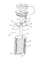
空調用複合装置12は、上壁27、下壁28及び周壁29を含むチャンバ26を備えている。このチャンバ26には、内部熱交換器5、分離エリア19及びアキュムレーションエリア20が収容されている。また、このチャンバ26には、分離エリア19及びアキュムレーションエリア20間の隔壁である境界壁31と、内部熱交換器5及びアキュムレーションエリア20間の隔壁である制限壁32と、制限壁32及び境界壁31間を連通するパイプ33とを備える内部コンポーネント30が収容されている。
【選択図】図2An air conditioning composite apparatus suitable for a vehicle or the like, easy to manufacture and assemble, and an air conditioning loop including the same.
[Solution]
The air conditioning composite apparatus 12 includes a chamber 26 including an upper wall 27, a lower wall 28, and a peripheral wall 29. The chamber 26 accommodates the internal heat exchanger 5, the separation area 19, and the accumulation area 20. The chamber 26 includes a boundary wall 31 that is a partition wall between the separation area 19 and the accumulation area 20, a restriction wall 32 that is a partition wall between the internal heat exchanger 5 and the accumulation area 20, a restriction wall 32, and a boundary wall. An internal component 30 including a pipe 33 communicating between 31 is accommodated.
[Selection] Figure 2
Description
本発明は空調用複合装置に関し、主として、車両の暖房、換気及び/又は空調システムと共に動作する内部熱交換器及びアキュムレータを含む空調用複合装置、及びそれを含む空調ループに関する。 The present invention relates to an air conditioning composite apparatus, and more particularly to an air conditioning composite apparatus including an internal heat exchanger and an accumulator operating with a vehicle heating, ventilation and / or air conditioning system, and an air conditioning loop including the same.
車両には、その内部の空気温度パラメータを調整するために、暖房、換気及び/又は空調システムを備えているのが一般的である。このシステムは、主として車両の機器パネルの下方に設けられたプラスチック材料製のケースを備えている。このケースは、少なくとも1つの空気流を、車両の内部へ送り出す前にチャネリングする。 A vehicle is typically equipped with a heating, ventilation and / or air conditioning system to adjust its internal air temperature parameters. This system includes a case made of a plastic material provided mainly under a device panel of a vehicle. In this case, at least one air flow is channeled before being sent into the vehicle.
かかるシステムにおいては、空調ループと協働して、空気流を、車両内部へケースから放出する前に冷却する。この空調ループは、複数のエレメントを有し、特にR744と称される炭酸ガスであるスーパークリチカル流体の如き冷媒を循環させている。これらのエレメントは、少なくとも1個のコンプレッサ、ガスクーラ、内部熱交換器、膨張器、気化器及びアキュムレータを含んでいる。 In such a system, in cooperation with the air conditioning loop, the airflow is cooled before it is released from the case into the vehicle. This air-conditioning loop has a plurality of elements and circulates a refrigerant such as a supercritical fluid which is carbon dioxide, particularly called R744. These elements include at least one compressor, gas cooler, internal heat exchanger, expander, vaporizer and accumulator.
冷媒は、コンプレッサからガスクーラへ、次に内部熱交換器の「高圧」ブランチを介し、更に膨張器、気化器、アキュムレータ、そして最後に、内部熱交換器の「低圧」ブランチへ循環して、コンプレッサへ戻る。 The refrigerant is circulated from the compressor to the gas cooler, then through the “high pressure” branch of the internal heat exchanger, and further to the expander, vaporizer, accumulator, and finally to the “low pressure” branch of the internal heat exchanger. Return to.
このコンプレッサは、ガス状の冷媒を受けるように設計されており、それを加圧して高圧にする。ガスクーラは、加圧された冷媒を冷却し、熱を環境へ移動させることにより、ほぼ一定圧力で加圧された冷媒を、冷却することができる。膨張部材は、冷媒の少なくとも一部を液状態にすることにより、ガスクーラから遠ざかる冷媒の圧力を低下させることができる。気化器は、冷媒を、ガス状態から液状態に変換して、ほぼ一定圧力で膨張器から戻し、気化器を通過する空気流の熱を取り出す。次に、気化又は蒸発した冷媒は、コンプレッサで吸い上げられる。かかる構成において、冷媒は、内部熱交換器の「高圧」ブランチ内では高圧であり、他方内部熱交換器の「低圧」ブランチ内では低圧である。 This compressor is designed to receive a gaseous refrigerant and pressurizes it to a high pressure. The gas cooler can cool the pressurized refrigerant at a substantially constant pressure by cooling the pressurized refrigerant and transferring heat to the environment. The expansion member can reduce the pressure of the refrigerant moving away from the gas cooler by bringing at least a part of the refrigerant into a liquid state. The vaporizer converts the refrigerant from a gas state to a liquid state, returns the refrigerant from the expander at a substantially constant pressure, and extracts the heat of the air flow passing through the vaporizer. Next, the vaporized or evaporated refrigerant is sucked up by a compressor. In such a configuration, the refrigerant is at high pressure in the “high pressure” branch of the internal heat exchanger, while at low pressure in the “low pressure” branch of the internal heat exchanger.
アキュミレータは、冷媒のガス状態及び液状態を分離する機能を有する。そのために、アキュムレータは、内部で重量差により両状態を相互に分離する分離エリアを有する。 The accumulator has a function of separating the gas state and the liquid state of the refrigerant. For this purpose, the accumulator has a separation area that separates the two states from each other by the weight difference.
またアキュムレータは、空調ループの使用状態により冷媒の循環負荷を蓄積する機能を有する。アキュムレータは、冷媒を液状態で貯蔵する亜キュムレーションエリアを有し、このアキュムレーションエリアは、分離エリアからの液状冷媒を収集する。 The accumulator also has a function of accumulating the refrigerant circulation load depending on the use state of the air conditioning loop. The accumulator has a sub-cumulation area for storing the refrigerant in a liquid state, and this accumulation area collects the liquid refrigerant from the separation area.
一般に、アキュムレータは、分離エリア、及びアキュムレーションエリアを収容するチャンバを備え、このチャンバは、アキュムレーションエリアをチャンバの底部に制限する下隔壁を備えている。よって、気化器からガス状及び液状で来る冷媒のうち液状の冷媒は、重力により、アキュムレーションエリア内の下隔壁の上に貯蔵される。 In general, the accumulator includes a separation area and a chamber that houses the accumulation area, and the chamber includes a lower partition that limits the accumulation area to the bottom of the chamber. Therefore, the liquid refrigerant out of the refrigerant that comes in gaseous and liquid form from the vaporizer is stored on the lower partition wall in the accumulation area by gravity.
内部熱交換器は、「高圧」ブランチ内を循環する冷媒が、「低圧」ブランチ内を循環している冷媒へ熱を伝えることができるように設計されている。 The internal heat exchanger is designed so that the refrigerant circulating in the “high pressure” branch can transfer heat to the refrigerant circulating in the “low pressure” branch.
(株)日本自動車部品総合研究所、及び(株)デンソーの日本特許公開公報(特開平10−019421号)の「冷凍サイクル及びこのサイクルに用いるアキュムレータ」は、内部熱交換器及びアキュムレータを合体して1つの装置にすることを提案している。一般に、アキュムレータはチャンバを有し、このチャンバには、蓋で閉じられる開口が設けられている。このチャンバは、この一体化装置を、空調ループで使用中の位置で、液状冷媒のために内部熱交換器をアキュムレーションエリアに吊り下げて、内部熱交換器を収容している。 “Refrigerating cycle and accumulator used in this cycle” in Japan Automobile Parts Research Institute, Inc. and Denso Corporation's Japanese Patent Publication (Japanese Patent Application Laid-Open No. 10-019421) are a combination of an internal heat exchanger and an accumulator. It is proposed to use one device. In general, accumulators have a chamber, which is provided with an opening that is closed with a lid. This chamber houses the internal heat exchanger by suspending the internal heat exchanger in the accumulation area for the liquid refrigerant at a position where the integrated device is in use in the air conditioning loop.
上述の如き一体化装置は、構成が極めて複雑であるので、単純化するのが好ましい。 The integrated device as described above is extremely complicated in configuration, and is preferably simplified.
また、上述の如き従来の一体化装置は、相当数の個別部品により構成されているので、製造コストを低減する必要がある。 Further, since the conventional integrated device as described above is constituted by a considerable number of individual parts, it is necessary to reduce the manufacturing cost.
特に、上述の如き従来の一体化装置は嵩張るので、小型化するのが望ましい。 In particular, since the conventional integrated device as described above is bulky, it is desirable to reduce the size.
更に、空調ループの内部を循環する冷媒に潤滑オイルが加えられる通常の場合には、かかる一体化装置の構成は、空調ループ内で、貯蔵又はインテグレーションを行うことができない。 Furthermore, in the normal case where lubricating oil is added to the refrigerant circulating in the air conditioning loop, such an integrated device configuration cannot be stored or integrated within the air conditioning loop.
最後に、かかる一体化装置は、それが実行する多機能に関し、改善又は改良することが必要である。特に、一体化装置は、以下の点で最適化する必要がある。
* 気化器から来るガス状及び液状冷媒の分離を改善する。
* 「低圧」ブランチ内を循環する冷媒、及び「高圧」ブランチ内を循環する冷媒間の熱交換を最適化するために、「低圧」ブランチ内の冷媒の循環を改善する。
* この装置を構成する種々の構成要素の製造が、簡単かつ迅速になるようにする。
* これら種々の構成要素を、相互に簡単かつ迅速に組立可能にする。
Finally, such an integrated device needs to be improved or improved with respect to the multi-function it performs. In particular, the integrated device needs to be optimized in the following points.
* Improve the separation of gaseous and liquid refrigerant coming from the vaporizer.
* Improve refrigerant circulation in the "low pressure" branch to optimize heat exchange between the refrigerant circulating in the "low pressure" branch and the refrigerant circulating in the "high pressure" branch.
* Make the production of the various components that make up the device simple and fast.
* Make these various components easy and quick to assemble with each other.
本発明は、従来技術の上述した課題に鑑みなされたものであり、その第1の目的は、内部熱交換器及び空調ループに含まれるアキュムレータに関連して、次のように構成された空調用複合装置を提供することを目的とする。
* 空調ループ内を循環するガス状冷媒及び液状冷媒の分離を改善する。
* 内部熱交換器の「低圧」ブランチ内の冷媒の循環を改善して、「低圧」ブランチ内を循環する冷媒と「高圧」ブランチ内を循環する冷媒間の熱交換を最適化する。
* 空調装置を構成する種々の要素又は部品間のシールを改善する。
この空調用複合装置は、最適化したオイル溜めを備え、空調ループ内にオイルを再注入し、種々の構成要素の製造を、容易かつ迅速とし、さらに、各構成要素間の組立を、容易かつ迅速とする。
The present invention has been made in view of the above-mentioned problems of the prior art, and a first object thereof is an air conditioning system configured as follows in relation to an internal heat exchanger and an accumulator included in an air conditioning loop. An object is to provide a composite device.
* Improve the separation of gaseous and liquid refrigerants circulating in the air conditioning loop.
* Improve refrigerant circulation in the “low pressure” branch of the internal heat exchanger to optimize heat exchange between refrigerant circulating in the “low pressure” branch and refrigerant circulating in the “high pressure” branch.
* Improve the seal between the various elements or parts that make up the air conditioner.
This air conditioning composite device is equipped with an optimized oil sump, re-injecting oil into the air conditioning loop, making it easy and quick to manufacture the various components, and easy to assemble between the components. Be quick.
本発明の第2の目的は、上述した空調用複合装置を含み、各種デザインの空調ループ内に組み込み可能にし、この空調ループの動作効率(COP)を改善する空調ループを提供することである。 A second object of the present invention is to provide an air-conditioning loop that includes the above-described air-conditioning composite apparatus, can be incorporated in an air-conditioning loop of various designs, and improves the operating efficiency (COP) of the air-conditioning loop.
上述した従来技術の課題を解決し、上述した目的を達成するために、本発明の空調用複合装置、及びそれを含む空調ループは、次のような特徴的な構成を採用している。 In order to solve the above-described problems of the prior art and achieve the above-described object, the air-conditioning composite apparatus of the present invention and the air-conditioning loop including the same employ the following characteristic configuration.
本発明による空調用複合装置は、上隔壁、下隔壁、及び少なくとも1個の周壁により構成されるチャンバを備えている。このチャンバには、内部熱交換器、分離エリア及びアキュムレーションエリアが収容されている。また、このチャンバには、分離エリア、及びアキュムレーションエリアの境界を定める境界壁、アキュムレーションエリアに対して、内部熱交換器を制限する制限壁、及びこの制限壁と境界壁とを連通するパイプにより構成される一体の内部コンポーネントが収容されている。 The composite apparatus for air conditioning according to the present invention includes a chamber constituted by an upper partition wall, a lower partition wall, and at least one peripheral wall. The chamber houses an internal heat exchanger, a separation area and an accumulation area. In addition, the chamber includes a separation area, a boundary wall that defines the boundary of the accumulation area, a restriction wall that restricts the internal heat exchanger with respect to the accumulation area, and a pipe that communicates the restriction wall and the boundary wall. The integrated internal components are housed.
本発明による空調ループは、主として上述した空調用複合装置を含むことを特徴としている。
ガス状冷媒及び液状冷媒間の分離を行う分離エリア、及びこの分離エリアから来る液状冷媒を貯蔵するループを備える空調ループを、スーパークリチカル冷媒が通過する。
The air-conditioning loop according to the present invention is mainly characterized by including the above-described air-conditioning composite apparatus.
The supercritical refrigerant passes through an air conditioning loop including a separation area for separating the gaseous refrigerant and the liquid refrigerant and a loop for storing the liquid refrigerant coming from the separation area.
上述の如き特徴的な構成を有する本発明の空調用複合装置、及びそれを含む空調ループによると、次の如き特有の効果が奏せられる。即ち、本発明の空調用複合装置は、内部熱交換器及びアキュムレータを一体化アセンブリとしているので、小型化かつ軽量化が可能であると共に、安価に製造可能であり、更に単一の組立操作で、簡単かつ迅速に組立可能である。かかる一体アセンブリの空調用複合装置を有する空調ループは、高い効率で動作可能である。 According to the composite apparatus for air conditioning of the present invention having the characteristic configuration as described above and the air conditioning loop including the same, the following specific effects can be obtained. That is, the air conditioning composite apparatus of the present invention has an internal heat exchanger and an accumulator as an integrated assembly, so that it can be reduced in size and weight, can be manufactured at low cost, and can be manufactured in a single assembly operation. Easy and quick assembly. An air conditioning loop having such an integrated air conditioning composite device can operate with high efficiency.
本発明の空調用複合装置およびそれを含む空調ループの、各種の実施形態について、添付図面に基づく以下の詳細な説明を参照することにより、本発明をよく理解することができ、かつその詳細も明らかになると思う。 Referring to the following detailed description based on the accompanying drawings, various embodiments of an air conditioning composite apparatus and an air conditioning loop including the same of the present invention can be well understood, and the details thereof can also be understood. I think it will be clear.
以下、添付図面を参照して、本発明による空調用複合装置、及びそれを含む空調ループの好適な実施の形態について詳述する。図1において、空調ループ1と協働する車両の暖房、換気、及び/又は空調システムは、車両の内部へ送られる前の空気流2を冷却する。この空調ループ1は、コンプレッサ3、ガスクーラ4、内部熱交換器5、膨張器6、気化器7及びアキュムレータ8を有し、スーパークリチカル流体、特にR744と称される炭酸ガスの如き冷媒が循環する。潤滑オイルの如き添加物が冷媒と混合され、コンプレッサ3の動作を維持する。この潤滑オイルは、冷媒の濃度以上の濃度を有する。
Hereinafter, with reference to the accompanying drawings, a preferred embodiment of an air conditioning composite device and an air conditioning loop including the same will be described in detail. In FIG. 1, a vehicle heating, ventilation, and / or air conditioning system cooperating with an
冷媒は、コンプレッサ3からガスクーラ4、内部熱交換器5の「高圧」ブランチ9、膨張器6、気化器7、アキュムレータ8及び最後に内部熱交換器5の「低圧」ブランチ10を循環して、コンプレッサ3へ戻る。この構成により、「高圧」ブランチ9内の高圧かつ高温の冷媒、及び「低圧」ブランチ10内の低圧かつ低温の冷媒間で熱交換を可能にする。これにより、空調ループ1の動作効率(COP)は改善される。
The refrigerant circulates from the
空調ループ1は、コンプレッサ3の出口を始点とし、膨張器6を終点とする「高圧」ライン17を有し、空調ループ1内の冷媒は、この「高圧」ライン17内を循環方向11へ循環する。ガスクーラ4及び内部熱交換器5の「高圧」ブランチ9は、「高圧」ライン17の始点及び終点間に挿入されている。
The
また、空調ループ1は、膨張器6の出口を始点とし、コンプレッサ3の入口を終点とする「低圧」ライン18を備えている。空調ループ1内で、冷媒は、「低圧」ライン18内を循環方向11へ循環する。気化器7及び内部熱交換器5の「低圧」ブランチ10は、「低圧」ライン18の始点及び終点間に挿入されている。
The
空調ループ1内の冷媒の循環方向11の下流に配置されたアキュムレータ8は、気化器7から来るガス状冷媒と液状冷媒を分離し、液状冷媒及び潤滑オイルを回収する。このために、アキュムレータ8は、ガス状冷媒及び液状冷媒の分離を行う分離エリア19、及び液状冷媒の回収を行うアキュムレーションエリア20を備えている。
An accumulator 8 disposed downstream of the
内部熱交換器5及びアキュムレータ8は、空調用複合装置(以下、単に複合装置という場合もある)12に関連づけられ、一体構成であり、協働して、内部熱交換器5及びアキュムレータ8の機能を果たす。この複合装置12の複合かつ一体の構成により、内部熱交換器5及びアキュムレータ8を、空調ループ1に同時に取付可能にする。即ち、内部熱交換器5及びアキュムレータ8は、一体的に組み立てられている。この特定の構成により、アキュムレータ8の出口22及び内部熱交換器5の「低圧」ブランチ10の入口23間を、車両のエンジンルーム(又はコンパートメント)内に取り付けられるパイプをなくすことが可能になる。
The
複合装置12は、ガスクーラから来る冷媒が、複合装置12内に取り込まれる「高圧」入口13を備えている。また、この複合装置12は、この複合装置12から高圧の冷媒を、膨張器6に向けて放出する「高圧」出口14を備えている。「高圧」入口13及び「高圧」出口14は、「高圧」ブランチ9を備えている「高圧」循環パス24により、相互に接続されている。
The
また、複合装置12は、「低圧」入口15を備え、気化器7から来る冷媒が底から入り込むようにしている。最後に、複合装置12は、「低圧」出口16を備え、低圧の冷媒が、複合装置12からコンプレッサ3へ放出される。「低圧」入口15及び「低圧」出口16は、内部熱交換器5の「低圧」ブランチ10、及び分離エリア19を含む「低圧」循環パス25で、相互に連結されている。
The
図2及び図3において、複合装置12は、上隔壁27、下隔壁28、及び少なくとも1個の周壁29により構成されるチャンバ26を含んでいる。周壁29は、細長いチューブ状であり、その両端は、上隔壁27を形成する上蓋及び下隔壁28を形成する下蓋により閉じられている。このチャンバ26には、内部熱交換器5、分離エリア19及びアキュムレーションエリア19が収容されている。
2 and 3, the
希望する機能、特にガス状冷媒及び液状冷媒の分離、冷媒、及び/又はオイルのストレージ、及びオイルのコンプレッサ3の上流への再統合等を確実にするために、分離エリア19、アキュムレーションエリア20及び内部熱交換器5の相互配置と共に、複合装置12のデザインの問題が生じる。
In order to ensure the desired function, in particular the separation of gaseous and liquid refrigerants, the storage of refrigerant and / or oil, the reintegration of oil upstream of the
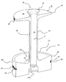
本発明によると、チャンバ26には、分離エリア19及びアキュムレーションエリア20を仕切る境界壁31、アキュムレーションエリア20に対する内部熱交換器5を制限する制限壁32、及び制限壁32と境界壁31を連通するパイプ33により形成されている内部一体コンポーネント30が収容されている。
According to the present invention, the
本発明の設計者は、単一の内部一体コンポーネント30として、複合装置12の全ての機能を意図的に含める構成を選択した。この選択により、複合装置12の組立体を小型化かつ軽量化するとともに、この内部一体化コンポーネント30を、低価格で容易に製造可能にした。
The designer of the present invention has selected a configuration that intentionally includes all the functions of the
内部コンポーネント30を一体化することにより、内部コンポーネント30を、境界壁31、制限壁32及びパイプ33よりなる一体アセンブリ、又は組立体とし、この一体アセンブリ31、32、33を、単一組立動作で、チャンバ26内に一緒に取付可能にしている。本発明の第1実施例によると、一体アセンブリ31、32、33は、例えばプラスチック材料により、一体に製造可能である。本発明の他の実施例によると、一体アセンブリ31、32、33は、境界壁31及びパイプ33を、入れ子、接着、又はその他により組み立てられ制限壁32と一体アセンブリとする2体構造とされる。或いは、境界壁31を、パイプ33及び制限壁32と一体アセンブリとする。
By integrating the
境界壁31は、分離エリア19及びアキュムレーションエリア20を相互に部分的に隔離している。境界壁31は、分離エリア19及びアキュムレーションエリア20間に挿入される。
The
制限壁32は、アキュムレーションエリア20及び熱交換器5を相互に隔離している。熱交換器5は、制限壁32及び下隔壁28間に挿入されている。従って、アキュムレーションエリア20は、境界壁31及び制限壁32間に挿入されることが明らかである。
The limiting
パイプ33は、アキュムレーションエリア20の内部を通って、境界壁31及び制限壁32間に挿入されている。パイプ33は、境界壁31を貫通して設けられた第1開口35を有する第1端34及び制限壁32を貫通して設けられた第2開口37を有する第2端36よりなっている。パイプ33は、第1開口35により分離エリア19と連通すると共に第2開口37により熱交換器5と気体的に連通し、内部容積38を制限している。かかる構成により、パイプ33の内部容積38は、ガス状の冷媒を、分離エリア19から、内部熱交換器5の「低圧」ブランチ10の入口23へ通過可能にする。
The
境界壁31には、カラー39が第1開口35の周りに、境界壁31から分離エリア19に向けて膨らむように設けられている。これは、ガス状の冷媒を、パイプ33の内部容積38へ取り込み可能にすると共に、液状冷媒がパイプ33の内部容積38内に取り込まれるのを阻止する。その結果、気化器7から来る冷媒は、複合装置12の「低圧」入口15に設けられたノズル40により、分離エリア19に取り入れられた後、サイクロン効果により、気体と液体に分離される。ノズル40は、例えばタンジェンシャルオリフィス41を有するシリンダとされ、ガス状冷媒及び液状冷媒の分離を行う。液状冷媒は、重力によりノズル40から境界壁31へ落下し、ガス状冷媒は、分離エリア19内に分散し、その後に、内部容積38の内部を貫通する。
A
境界壁31は、ディスク又は円板状とされ、その中心42に、第1開口35が形成され、そのエッジ43にラグ44が設けられ、境界壁31をチャンバ26の周壁29に対して位置決めする。
The
図3において、制限壁32には、少なくとも部分的に内部熱交換器5を取り囲むようにスカート45が設けられている。このスカート45は、内部熱交換器5を覆い、それを、チャンバ26の周壁29から隔離している。スカート45には、例えば溝46が設けられ、スカート45を周壁29に接触させている。スカート45は、チャンバ26の下隔壁28に接触する下境界47を備えている。
In FIG. 3, the
上述した構成により、チャンバ26の下隔壁28を貫通して設けられた「高圧」入口13と、チャンバ26の上隔壁27を貫通して設けられた「高圧」出口14間の「高圧」循環パス24は、複合装置12の一側から他側へ、複合装置12の長手方向の延長Δとほぼ平行に、図2及び図3の底部から頂部へ、即ち重力gの方向と逆方向に通過する。
With the above-described configuration, the “high pressure” circulation path between the “high pressure”
また、上述した各エリアの配置により、「低圧」循環パス25は、チャンバ26の上隔壁27を貫通して設けられた「低圧」入口15及びチャンバ26の下隔壁28を貫通して設けられた「低圧」出口16間に延び、複合装置12の一端から他端へ複合装置12の長手延長Δの軸とほぼ平行に、図2及び図3の頂部から底部へ、即ち重力gと同じ方向を通過する。
Further, due to the arrangement of each area described above, the “low pressure”
「高圧」循環パス24及び「低圧」循環パス25の延長の例外は、図5を参照して後述する内部熱交換器5内で生じる交換である。
An exception to the extension of the “high pressure”
最後に、本発明の特徴は、上隔壁27にノズル40が設けられていることである。換言すると、複合装置12におけるノズル40の識別により、隔壁27と28を決定し、上隔壁が複合装置12の使用位置であるか、又はその実際の動作位置であるかを示すことである。
Finally, a feature of the present invention is that the
本発明の好適な実施形態によると、上隔壁27は、取り外し可能な上蓋となっており、「低圧」入口15、及び「高圧」出口14が設けられている。一方、下隔壁28は、取り外し可能な底蓋とされ、「高圧」入口13及び「低圧」出口16が設けられている。
According to a preferred embodiment of the present invention, the
図3中の内部熱交換器5の位置における複合装置12の横断面である図4において、「高圧」入口13は、周辺「高圧」コレクタ51と連通しており、これは、フラットチューブ21の周辺端52と関連している。このフラットチューブ21は、長手延長Δの軸の周りに回転しており、その中心端49は、上記軸と一致している。中心端49には、中心「高圧」コレクタ48が設けられ、この少なくとも一部は、パイプ33の内部に収容されている。よって、パイプ33は、パイプ33の内部容積38の内部で循環する低圧冷媒と、中央「高圧」コレクタ48内部を循環する高圧冷媒間の熱交換の相補エリアを形成する。その結果、内部一体コンポーネント30の如く、パイプ33の内部容積38内に収容された中心「高圧」コレクタ48が設けられていない内部熱交換器5に対して、熱交換効率が3%〜7%のオーダーで増加する。
In FIG. 4, which is a cross section of the
フラットチューブ21は、2個の2次フラットチューブ50と境界をなし、その内部を低圧冷媒が循環する。本発明の他の実施形態によると、フラットチューブ21は、内側又は外側の単一の2次フラットチューブ50と境界をなしている。更に他の実施形態によると、フラットチューブ21は、単に低圧冷媒で洗われ、渦巻状のフラットチューブ21の連続するターン間の空間の内側を流れる。
The
図5において、中心「高圧」コレクタ48は、下キャップ53が設けられた中央チューブ内に配置されており、周辺「高圧」コレクタ51は、上キャップ54が設けられた周辺チューブ内に配置されている。内部熱交換器5は、巻回されたフラットチューブ21及びオプションの2次フラットチューブ50を覆う上プレート55、及び巻回されたフラットチューブ21、及びオプションの2次フラットチューブ50を覆う下プレート56を備えている。上プレート55及び下プレート56は、それぞれ、フラットチューブ21及びオプションの2次フラットチューブ50の一部分と接触している。
In FIG. 5, a central “high pressure”
上プレート55には、上プレート55を越えて上キャップ54が通過するオリフィス59が設けられている。また、上プレート55には、中央クラウン又は王冠状部60が、その外面61に設けられている。この外面61は、フラットチューブ21及びオプションの2次フラットチューブ50と接触していない面である。中央クラウン60には、溝62が設けられ、そこに、図8に示す如き第1シール76を受ける。中央クラウン60は、中心「高圧」コレクタ48が挿通する通路63を備えている。最後に、上プレート55は、細長い孔100を備えている。この孔100により、制限壁32の外面77と上プレート55間に溜まるオイルを通過させ、内部一体コンポーネントが、図9又は図10に示すように使用されるとき、通過したオイルを「低圧」出口16に向けて導く。
The
下プレート56には、「低圧」出口16の反対側に孔64が設けられ、この穴64を介して複合装置12からコンプレッサ3へ冷媒を放出する。また、この下プレート56には、その一部分にフィンガ65が設けられ、上述したスカート45に設けられた対応する窓66の内側とネスティング又は係合させる。この窓66は、図6に図示されている。
The
図6において、スカート45には切り込み67が設けられ、「低圧」冷媒がスカート45の何れの側へも通過可能にするので、スカート45とチャンバ26の周壁29間を流れる冷媒が回収可能である。
In FIG. 6, the
図7において、下プレート56は、上ベースプレート68及び下ベースプレート69を含む2枚のベースプレート68、69により構成されている。オイル溜めが上ベースプレート68と下ベースプレート69間に設けられている。下ベースプレート69には、オイルフィルタ72を受けるための放射状の切り欠き71が設けられている。
In FIG. 7, the
図8〜図10において、制限壁32は、境界壁31の反対側に設けられた内面73を備えている。ここで、制限壁32及び境界壁31は相互に平行であり、複合装置12の長手延長Δの軸及びパイプ33の対称軸とほぼ直交している。
8 to 10, the limiting
図8において、内面73は、境界壁31から見ると凸状であり、液状冷媒と一緒になった潤滑オイルは、内面73に沿って容易に流れ、周壁29及びスカート45間に拡散し、上述した放射状の切り欠き71を介して、低圧出口16へ到達する。
In FIG. 8, the
制限壁32は、第1スロット75が設けられた内部エッジ74を備え、制限壁32及び内部熱交換器5を構成する中央クラウン60間に、上述した第1シール76を受ける。
The
制限壁32は、内面73の反対側に外面77を備え、凹部78が設けられ、内部熱交換器5の「高圧」コレクタ51上に設けられた上キャップ54を通過させる。
The limiting
図9及び図10において、内面73は曲面Cの中心を有する皿状に設計され、境界壁31及び制限壁32間に挿入されている。他の実施例によると、曲面Cの中心は、境界壁31の上に配置される。ドレイン状に設けられたベース79よりなる皿73は、冷媒と共に循環するオイルを集める。更に、制限壁32は、第2スロット81が設けられた外エッジ80を備え、制限壁32及び周壁29間に第2シール82を備えている。
9 and 10, the
図9において、チャンネル83が、制限壁32の内面73及び外面77間に形成されている。制限壁32の内面73と外面77間に延びるチャンネル83は、複合装置12の「低圧」出口16のレベル、即ち空調ループ1内部の冷媒の循環方向11により内部熱交換器5の下流で、潤滑オイルの再統合を可能にしている。これにより、オイルが存在するために、内部熱交換器5の内部での熱損失は制限されるが、これは、本発明に特有の効果の1つである。最後に、テーパ101が、外面77と内側エッジ74間の接合部に形成されていることに注目されたい。
In FIG. 9, a
図10において、内面73とパイプ33の内部38間に、孔84が設けられている。この孔84により、内部熱交換器5の「低圧」ブランチ10の入口23のレベル、即ち、空調ループ1の内部の循環方向11における内部熱交換器5の上流で、潤滑オイルの再統合を可能にしている。
In FIG. 10, a
以上、本発明による空調用複合装置、及びそれを含む空調ループの好適な実施形態の構成及び作用効果を、添付図面を参照して詳述した。しかし、この実施形態は、本発明の単なる例示に過ぎず、何ら本発明を限定するものではなく、以下の如き種々の変形や変更が可能であることに留意されたい。 The configuration and operational effects of the preferred embodiment of the air conditioning composite device according to the present invention and the air conditioning loop including the same have been described in detail with reference to the accompanying drawings. However, it should be noted that this embodiment is merely an example of the present invention and does not limit the present invention, and various modifications and changes as described below are possible.
上述の複合装置のパイプは、境界壁を貫通して形成された第1開口を有する第1端と、制限壁を貫通して形成された第2開口を有する第2端とを備えているのが好ましい。 The pipe of the composite device described above includes a first end having a first opening formed through the boundary wall and a second end having a second opening formed through the restriction wall. Is preferred.
上述の境界壁は、上述した第1開口の周りに形成されたカラーを備えているのが好ましい。このカラーは、分離エリアに向けて広がっているのが好ましい。 Preferably, the boundary wall includes a collar formed around the first opening described above. This collar preferably extends towards the separation area.
上述の境界壁は、ディスク状にデザインされ、その中心には、上述した第1開口が形成され、そのエッジには、少なくとも1個のラグが設けられ、境界壁をチャンバの周壁に対して位置決めしているのが好ましい。 The boundary wall described above is designed in a disk shape, the above-mentioned first opening is formed at the center thereof, and at least one lug is provided at the edge thereof, and the boundary wall is positioned with respect to the peripheral wall of the chamber. It is preferable.
上述の制限壁は、上述した分離壁の反対に位置する内面を備えているのが好ましい。 The limiting wall described above preferably has an inner surface located opposite to the separating wall described above.
上述の内面は、例えば上述した境界壁から見ると凸状の面である。 The above-mentioned inner surface is, for example, a convex surface when viewed from the above-described boundary wall.
更に、上述した内面は、例えば皿状に形成され、曲面Cの中心は、上述した境界壁及び制限壁の間、又は境界壁の上方に配置されている。 Furthermore, the above-described inner surface is formed in a dish shape, for example, and the center of the curved surface C is disposed between the boundary wall and the restriction wall described above or above the boundary wall.
上述の皿状部は、ドレイン状に形成されたベースを備えているのが好ましい。 The dish-shaped portion described above preferably includes a base formed in a drain shape.
上述の制限壁は、内部熱交換器を構成する中央クラウン及び制限壁間に第1シールを受けるための第1スロットが形成された内部エッジを備えるのが好ましい。 The limiting wall described above preferably comprises a central crown forming an internal heat exchanger and an internal edge formed with a first slot for receiving a first seal between the limiting walls.
また、上述の制限壁は、この制限壁と、上述した周壁間に、第2シールを受けるための第2スロットが設けられた外部エッジを備えているのが好ましい。 Moreover, it is preferable that the above-mentioned limiting wall is provided with the outer edge provided with the 2nd slot for receiving a 2nd seal between this limiting wall and the above-mentioned surrounding wall.
本発明の別の実施形態によると、少なくとも1個のチャネルが、上述の内面とパイプの内部容積間に設けられている。 According to another embodiment of the invention, at least one channel is provided between the aforementioned inner surface and the internal volume of the pipe.
本発明の更に他の実施形態によると、少なくとも1個の細管が、制限壁の外面、及びこれに対向する内面間に設けられている。 According to yet another embodiment of the present invention, at least one capillary is provided between the outer surface of the limiting wall and the inner surface opposite thereto.
上述の外面には、内部熱交換器の「低圧」コレクタ上に設けられる上キャップを通過させるための凹部が設けられているのが好ましい。 The outer surface described above is preferably provided with a recess for allowing the passage of an upper cap provided on the “low pressure” collector of the internal heat exchanger.
上述の制限壁には、上述の内部熱交換器を少なくとも部分的に包囲するためのスカートが設けられているのが好ましい。 The limiting wall is preferably provided with a skirt for at least partially surrounding the internal heat exchanger.
上述のスカートには、例えば複数の溝を設け、このスカートを、上述の周壁に接触させるのが好ましい。 It is preferable that the above-mentioned skirt is provided with, for example, a plurality of grooves, and this skirt is brought into contact with the above-described peripheral wall.
また、上述のスカートには、例えば下境界を設け、上述のチャンバの下隔壁に接触させるのが好ましい。 Moreover, it is preferable that the above-mentioned skirt is provided with, for example, a lower boundary and brought into contact with the above-described lower partition wall of the chamber.
上述のスカートには、少なくとも1個の窓を設け、上述の内部熱交換器の下プレートに設けられた対応する少なくとも1個のフィンガを受けるようにするのが好ましい。 The skirt described above is preferably provided with at least one window for receiving at least one corresponding finger provided on the lower plate of the internal heat exchanger described above.
本発明の空調用複合装置は、次の2つの循環パスを備えているのが好ましい。
*チャンバの下隔壁を貫通して設けられた「高圧」入口、及びチャンバの上隔壁を貫通して設けられた「高圧」出口間に延び、主として内部熱交換器の「高圧」ブランチ、及びパイプの内部容積内に少なくとも部分的に収容される内部熱交換器の「高圧」コレクタを備える「高圧」循環パス。
*チャンバの上隔壁を貫通する「低圧」入口、及びチャンバの下隔壁を貫通して設けられた「低圧」入口、及びチャンバの下隔壁を貫通して設けられた「低圧」出口間に延び、内部熱交換器の「低圧」ブランチ、パイプの内部容積及び分離エリアを含む「低圧」循環パス。
The composite apparatus for air conditioning according to the present invention preferably includes the following two circulation paths.
* Extends between the "high pressure" inlet provided through the lower bulkhead of the chamber and the "high pressure" outlet provided through the upper bulkhead of the chamber, mainly the "high pressure" branch of the internal heat exchanger, and the pipe A “high pressure” circulation path comprising a “high pressure” collector of an internal heat exchanger housed at least partially within the internal volume of the.
* Extending between a "low pressure" inlet through the upper bulkhead of the chamber, a "low pressure" inlet provided through the lower bulkhead of the chamber, and a "low pressure" outlet provided through the lower bulkhead of the chamber, A “low pressure” circulation path including the “low pressure” branch of the internal heat exchanger, the internal volume of the pipe and the separation area.
上述のパイプは、パイプの内部容積内を循環する低圧冷媒及び「高圧」コレクタ内を循環する高圧冷媒間の相補熱交換エリアを構成しているのが好ましい。 The pipe described above preferably constitutes a complementary heat exchange area between the low pressure refrigerant circulating in the internal volume of the pipe and the high pressure refrigerant circulating in the “high pressure” collector.
1 空調ループ
2 空気流
3 コンプレッサ
4 ガスクーラ
5 内部熱交換器
6 膨張器
7 気化器
9 「高圧」ブランチ
10 「低圧」ブランチ
11 「高圧」ライン
12 空調用複合装置
16 低圧出口
18 「低圧」ライン
19 分離エリア
20 アキュムレーションエリア
26 チャンバ
27 上隔壁
28 下隔壁
29 周壁
30 一体内部コンポーネント
31 境界壁
32 制限壁
33 パイプ
34 第1端
35 第1開口
36 第2端
37 第2開口
38 内部
39 カラー
43 エッジ
44 ラグ
45 スカート
54 上キャップ
55 上プレート
56 下プレート
60 中央クラウン
64 孔
68 上ベースプレート
69 下ベースプレート
71 切り欠き
72 オイルフィルタ
73 制限壁の内面
74 内部エッジ
75 第1スロット
76 第1シール
77 制限壁の外面
80 外部エッジ
81 第2スロット
82 第2シール
83 チャンネル
84 孔
100 孔
101 テーパ
DESCRIPTION OF
Claims (15)
前記分離エリア、及び前記アキュムレーションエリアの境界をなす境界壁と、前記アキュムレーションエリアに対して、前記内部熱交換器を制限する制限壁と、前記境界壁及び前記制限壁を連結するパイプとを備える一体内部コンポーネントを、前記チャンバに収容してあることを特徴とする空調用複合装置。 An air conditioning composite apparatus comprising an upper partition wall, a lower partition wall, and at least one peripheral wall, and including a chamber that houses an internal heat exchanger, a separation area, and an accumulation area,
Integral comprising: the separation area; a boundary wall that forms a boundary between the accumulation areas; a restriction wall that restricts the internal heat exchanger with respect to the accumulation area; and a pipe that connects the boundary wall and the restriction wall. An air conditioning composite apparatus in which an internal component is accommodated in the chamber.
前記分離エリアは、前記冷媒のうちガス状冷媒と液状冷媒を分離するエリアであり、
前記アキュムレーションエリアは、前記分離エリアから来る前記液状冷媒をストレージするエリアであることを特徴とする空調ループ。 The air conditioning loop of claim 14, wherein the supercritical refrigerant passes through the interior.
The separation area is an area for separating a gaseous refrigerant and a liquid refrigerant from the refrigerant,
The accumulation area is an area for storing the liquid refrigerant coming from the separation area.
Applications Claiming Priority (2)
| Application Number | Priority Date | Filing Date | Title |
|---|---|---|---|
| FR0807423A FR2940419B1 (en) | 2008-12-22 | 2008-12-22 | COMBINED DEVICE COMPRISING AN INTERNAL HEAT EXCHANGER AND AN ACCUMULATOR, AND PROVIDED WITH A MULTIFUNCTIONAL INTERNAL COMPONENT |
| FR0807423 | 2008-12-22 |
Publications (2)
| Publication Number | Publication Date |
|---|---|
| JP2010143574A true JP2010143574A (en) | 2010-07-01 |
| JP5421091B2 JP5421091B2 (en) | 2014-02-19 |
Family
ID=40627549
Family Applications (1)
| Application Number | Title | Priority Date | Filing Date |
|---|---|---|---|
| JP2009288803A Active JP5421091B2 (en) | 2008-12-22 | 2009-12-21 | Air conditioning composite device and air conditioning loop including the same |
Country Status (7)
| Country | Link |
|---|---|
| US (1) | US9464831B2 (en) |
| EP (1) | EP2199708B1 (en) |
| JP (1) | JP5421091B2 (en) |
| CN (1) | CN101762131B (en) |
| AT (1) | ATE530865T1 (en) |
| ES (1) | ES2375917T3 (en) |
| FR (1) | FR2940419B1 (en) |
Cited By (1)
| Publication number | Priority date | Publication date | Assignee | Title |
|---|---|---|---|---|
| JP2024536936A (en) * | 2021-02-17 | 2024-10-09 | ハンオン システムズ | Combination of refrigerant accumulator and internal heat exchanger for refrigerant, connecting parts, internal heat exchanger and accumulator |
Families Citing this family (11)
| Publication number | Priority date | Publication date | Assignee | Title |
|---|---|---|---|---|
| GB201411563D0 (en) * | 2014-06-30 | 2014-08-13 | Eaton Ind Ip Gmbh & Co Kg | Accumulator for an air conditioning system |
| US10539350B2 (en) * | 2016-02-26 | 2020-01-21 | Daikin Applied Americas Inc. | Economizer used in chiller system |
| US11460225B2 (en) * | 2017-06-23 | 2022-10-04 | Jack D. Dowdy, III | Power saving apparatuses for refrigeration |
| CN113432350B (en) * | 2020-03-20 | 2024-12-06 | 青岛海尔空调电子有限公司 | Pipeline oil cleaning device for air conditioning system and air conditioning system |
| DK180804B1 (en) * | 2020-04-15 | 2022-04-05 | Mayekawa Europe Nv | Cooling system and a method for operating a cooling system |
| CN114379310B (en) * | 2020-10-22 | 2025-09-09 | 绍兴三花汽车热管理科技有限公司 | Fluid management device and thermal management device |
| CN112325520A (en) * | 2020-11-23 | 2021-02-05 | 珠海格力电器股份有限公司 | Oil separating assembly, oil separator and air conditioning system |
| CN112923616B (en) * | 2021-01-30 | 2021-11-23 | 清华大学 | Air source CO for preventing evaporator from frosting by using heat of heat regenerator2Heat pump system |
| KR20230068815A (en) | 2021-11-11 | 2023-05-18 | 현대자동차주식회사 | Refrigerant moudule of integrated thermal management system for vehicle |
| KR20230068814A (en) | 2021-11-11 | 2023-05-18 | 현대자동차주식회사 | Refrigerant moudule of integrated thermal management system for vehicle |
| KR20230090753A (en) * | 2021-12-15 | 2023-06-22 | 현대자동차주식회사 | Heat exchanger and refrigerant moudule of integrated thermal management system for vehicle including the same |
Citations (12)
| Publication number | Priority date | Publication date | Assignee | Title |
|---|---|---|---|---|
| JPS4611800Y1 (en) * | 1968-02-14 | 1971-04-23 | ||
| JPH1019421A (en) * | 1996-07-05 | 1998-01-23 | Nippon Soken Inc | Refrigerating cycle and accumulator used for the cycle |
| JP2002206823A (en) * | 2000-11-09 | 2002-07-26 | Denso Corp | Accumulator module |
| JP2003004390A (en) * | 2001-04-05 | 2003-01-08 | Modine Mfg Co | Spiral fin/tube type heat exchanger |
| JP2004028525A (en) * | 2002-06-28 | 2004-01-29 | Zexel Valeo Climate Control Corp | Accumulator and refrigeration cycle using the same |
| JP2004100974A (en) * | 2002-09-05 | 2004-04-02 | Zexel Valeo Climate Control Corp | Accumulator and refrigeration cycle using it |
| JP2004176949A (en) * | 2002-11-25 | 2004-06-24 | Denso Corp | Heat exchanger |
| JP2004526934A (en) * | 2001-05-24 | 2004-09-02 | ハラ・クライメート・コントロール・カナダ・インコーポレーテッド | Internal heat exchanger accumulator |
| JP2006112778A (en) * | 2004-10-15 | 2006-04-27 | Valeo Klimasysteme Gmbh | Accumulator with internal heat exchanger for air-conditioning system |
| JP2008051426A (en) * | 2006-08-25 | 2008-03-06 | Valeo Thermal Systems Japan Corp | Accumulator |
| FR2913764A1 (en) * | 2007-03-12 | 2008-09-19 | Valeo Systemes Thermiques | HEAT EXCHANGER AND INTEGRATED ASSEMBLY INCORPORATING SUCH EXCHANGER |
| JP2010169387A (en) * | 2008-12-22 | 2010-08-05 | Valeo Systemes Thermiques | Composite device including internal heat exchanger and accumulator |
Family Cites Families (19)
| Publication number | Priority date | Publication date | Assignee | Title |
|---|---|---|---|---|
| US3060704A (en) * | 1959-11-20 | 1962-10-30 | Denco Miller Ltd | Refrigeration equipment |
| US3955375A (en) * | 1974-08-14 | 1976-05-11 | Virginia Chemicals Inc. | Combination liquid trapping suction accumulator and evaporator pressure regulator device including a capillary cartridge and heat exchanger |
| US4217765A (en) * | 1979-06-04 | 1980-08-19 | Atlantic Richfield Company | Heat exchanger-accumulator |
| JPH0285525A (en) | 1988-09-20 | 1990-03-27 | Fuji Technica Inc | Viscous coupling |
| US4942743A (en) * | 1988-11-08 | 1990-07-24 | Charles Gregory | Hot gas defrost system for refrigeration systems |
| US4938036A (en) * | 1989-03-06 | 1990-07-03 | Stanadyne Automotive Corp. | Combination air conditioning accumulator and fuel cooler |
| US5479790A (en) * | 1993-07-06 | 1996-01-02 | Bottum, Jr.; Edward W. | Suction accumulator structure |
| US5845502A (en) * | 1996-07-22 | 1998-12-08 | Lockheed Martin Energy Research Corporation | Heat pump having improved defrost system |
| DE19635454B4 (en) * | 1996-08-31 | 2010-06-17 | Behr Gmbh & Co. Kg | Collector heat exchanger assembly and air conditioning equipped therewith |
| US6584784B2 (en) * | 1999-02-05 | 2003-07-01 | Midwest Research Institute | Combined refrigeration system with a liquid pre-cooling heat exchanger |
| JP2002195677A (en) * | 2000-10-20 | 2002-07-10 | Denso Corp | Heat pump cycle |
| US6523365B2 (en) * | 2000-12-29 | 2003-02-25 | Visteon Global Technologies, Inc. | Accumulator with internal heat exchanger |
| US20030121648A1 (en) * | 2001-12-28 | 2003-07-03 | Visteon Global Technologies, Inc. | Counter-flow heat exchanger with optimal secondary cross-flow |
| DE10348141B3 (en) * | 2003-10-09 | 2005-02-03 | Visteon Global Technologies, Inc., Dearborn | Inner heat exchanger for high pressure cooling medium providing dual function as accumulator and cooling medium collector |
| JP2005299949A (en) * | 2004-04-07 | 2005-10-27 | Zexel Valeo Climate Control Corp | Internal heat exchanger and its manufacturing method |
| EP1782000A4 (en) * | 2004-07-09 | 2007-10-10 | Junjie Gu | Refrigeration system |
| US20060196223A1 (en) * | 2005-03-07 | 2006-09-07 | Halla Climate Control Canada Inc. | Accumulator with oil vanes/indentations |
| DE102005021787A1 (en) * | 2005-05-11 | 2006-11-16 | Modine Manufacturing Co., Racine | Transcritical air-conditioning refrigerant e.g. carbon-di-oxide, treating apparatus for use in e.g. automobile, has flat multi-chamber tube extruded to extend straight over length of vessel |
| JP4897298B2 (en) * | 2006-01-17 | 2012-03-14 | サンデン株式会社 | Gas-liquid separator module |
-
2008
- 2008-12-22 FR FR0807423A patent/FR2940419B1/en not_active Expired - Fee Related
-
2009
- 2009-12-07 AT AT09178157T patent/ATE530865T1/en not_active IP Right Cessation
- 2009-12-07 ES ES09178157T patent/ES2375917T3/en active Active
- 2009-12-07 EP EP09178157A patent/EP2199708B1/en active Active
- 2009-12-21 JP JP2009288803A patent/JP5421091B2/en active Active
- 2009-12-22 CN CN200910260699.4A patent/CN101762131B/en active Active
- 2009-12-22 US US12/644,329 patent/US9464831B2/en active Active
Patent Citations (12)
| Publication number | Priority date | Publication date | Assignee | Title |
|---|---|---|---|---|
| JPS4611800Y1 (en) * | 1968-02-14 | 1971-04-23 | ||
| JPH1019421A (en) * | 1996-07-05 | 1998-01-23 | Nippon Soken Inc | Refrigerating cycle and accumulator used for the cycle |
| JP2002206823A (en) * | 2000-11-09 | 2002-07-26 | Denso Corp | Accumulator module |
| JP2003004390A (en) * | 2001-04-05 | 2003-01-08 | Modine Mfg Co | Spiral fin/tube type heat exchanger |
| JP2004526934A (en) * | 2001-05-24 | 2004-09-02 | ハラ・クライメート・コントロール・カナダ・インコーポレーテッド | Internal heat exchanger accumulator |
| JP2004028525A (en) * | 2002-06-28 | 2004-01-29 | Zexel Valeo Climate Control Corp | Accumulator and refrigeration cycle using the same |
| JP2004100974A (en) * | 2002-09-05 | 2004-04-02 | Zexel Valeo Climate Control Corp | Accumulator and refrigeration cycle using it |
| JP2004176949A (en) * | 2002-11-25 | 2004-06-24 | Denso Corp | Heat exchanger |
| JP2006112778A (en) * | 2004-10-15 | 2006-04-27 | Valeo Klimasysteme Gmbh | Accumulator with internal heat exchanger for air-conditioning system |
| JP2008051426A (en) * | 2006-08-25 | 2008-03-06 | Valeo Thermal Systems Japan Corp | Accumulator |
| FR2913764A1 (en) * | 2007-03-12 | 2008-09-19 | Valeo Systemes Thermiques | HEAT EXCHANGER AND INTEGRATED ASSEMBLY INCORPORATING SUCH EXCHANGER |
| JP2010169387A (en) * | 2008-12-22 | 2010-08-05 | Valeo Systemes Thermiques | Composite device including internal heat exchanger and accumulator |
Cited By (3)
| Publication number | Priority date | Publication date | Assignee | Title |
|---|---|---|---|---|
| JP2024536936A (en) * | 2021-02-17 | 2024-10-09 | ハンオン システムズ | Combination of refrigerant accumulator and internal heat exchanger for refrigerant, connecting parts, internal heat exchanger and accumulator |
| JP7683013B2 (en) | 2021-02-17 | 2025-05-26 | ハンオン システムズ | Refrigerant accumulator and internal heat exchanger combination, connecting parts |
| US12540764B2 (en) | 2021-02-17 | 2026-02-03 | Hanon Systems | Combination of a refrigerant accumulator and an internal heat exchanger for refrigerant, connection component, internal heat exchanger and accumulator |
Also Published As
| Publication number | Publication date |
|---|---|
| EP2199708A1 (en) | 2010-06-23 |
| FR2940419A1 (en) | 2010-06-25 |
| ES2375917T3 (en) | 2012-03-07 |
| ATE530865T1 (en) | 2011-11-15 |
| EP2199708B1 (en) | 2011-10-26 |
| CN101762131B (en) | 2014-10-29 |
| US9464831B2 (en) | 2016-10-11 |
| FR2940419B1 (en) | 2010-12-31 |
| US20100155017A1 (en) | 2010-06-24 |
| JP5421091B2 (en) | 2014-02-19 |
| CN101762131A (en) | 2010-06-30 |
Similar Documents
| Publication | Publication Date | Title |
|---|---|---|
| JP5421091B2 (en) | Air conditioning composite device and air conditioning loop including the same | |
| US6523365B2 (en) | Accumulator with internal heat exchanger | |
| JP4519403B2 (en) | Receiver tank for refrigeration cycle, heat exchanger with receiver tank, and condensing device for refrigeration cycle | |
| KR101326841B1 (en) | Condenser for vehicle | |
| JP5497419B2 (en) | Combined internal heat exchanger and accumulator | |
| US11162721B2 (en) | Gas-liquid separation device for vehicle | |
| US20100101269A1 (en) | Compressor with improved oil separation | |
| JP2010156538A (en) | Combined device comprising internal heat exchanger and accumulator of air-conditioning loop | |
| US9920999B2 (en) | Heat exchanger and integrated air-conditioning assembly including such exchanger | |
| JP2011152827A (en) | Cooling media accumulating structure of vehicle air conditioning system | |
| KR20120086763A (en) | Condenser | |
| JP2016038196A (en) | Condenser | |
| JP2001174103A (en) | Refrigerant condenser | |
| KR101300556B1 (en) | Heat exchanger with accumulator of air conditioning system for automotive vehicles | |
| JP2008032269A (en) | Accumulator | |
| KR101510121B1 (en) | Air-conditining system for vehicle | |
| KR20170047050A (en) | A condenser | |
| CN210861855U (en) | Liquid storage device for compressor and compressor with same | |
| JP3955770B2 (en) | Heat exchanger with receiver tank and refrigeration system | |
| KR20120129677A (en) | Condenser for vehicle | |
| KR100950153B1 (en) | Heat exchange accumulator | |
| CN113162329A (en) | Cooling system and cooling method for motor of refrigeration centrifugal compressor | |
| CN112432538B (en) | Heat exchange assembly and thermal management system | |
| JP2010151393A (en) | Accumulator | |
| KR20130112497A (en) | Heat exchanger for an air conditioning system of a vehicle |
Legal Events
| Date | Code | Title | Description |
|---|---|---|---|
| A621 | Written request for application examination |
Free format text: JAPANESE INTERMEDIATE CODE: A621 Effective date: 20121016 |
|
| TRDD | Decision of grant or rejection written | ||
| A01 | Written decision to grant a patent or to grant a registration (utility model) |
Free format text: JAPANESE INTERMEDIATE CODE: A01 Effective date: 20131029 |
|
| A977 | Report on retrieval |
Free format text: JAPANESE INTERMEDIATE CODE: A971007 Effective date: 20131031 |
|
| A61 | First payment of annual fees (during grant procedure) |
Free format text: JAPANESE INTERMEDIATE CODE: A61 Effective date: 20131121 |
|
| R150 | Certificate of patent or registration of utility model |
Ref document number: 5421091 Country of ref document: JP Free format text: JAPANESE INTERMEDIATE CODE: R150 |
|
| R250 | Receipt of annual fees |
Free format text: JAPANESE INTERMEDIATE CODE: R250 |
|
| R250 | Receipt of annual fees |
Free format text: JAPANESE INTERMEDIATE CODE: R250 |
|
| R250 | Receipt of annual fees |
Free format text: JAPANESE INTERMEDIATE CODE: R250 |
|
| R250 | Receipt of annual fees |
Free format text: JAPANESE INTERMEDIATE CODE: R250 |
|
| R250 | Receipt of annual fees |
Free format text: JAPANESE INTERMEDIATE CODE: R250 |
|
| R250 | Receipt of annual fees |
Free format text: JAPANESE INTERMEDIATE CODE: R250 |
|
| R250 | Receipt of annual fees |
Free format text: JAPANESE INTERMEDIATE CODE: R250 |
|
| R250 | Receipt of annual fees |
Free format text: JAPANESE INTERMEDIATE CODE: R250 |
|
| R250 | Receipt of annual fees |
Free format text: JAPANESE INTERMEDIATE CODE: R250 |
|
| R250 | Receipt of annual fees |
Free format text: JAPANESE INTERMEDIATE CODE: R250 |