JP4519403B2 - Receiver tank for refrigeration cycle, heat exchanger with receiver tank, and condensing device for refrigeration cycle - Google Patents
Receiver tank for refrigeration cycle, heat exchanger with receiver tank, and condensing device for refrigeration cycle Download PDFInfo
- Publication number
- JP4519403B2 JP4519403B2 JP2002519847A JP2002519847A JP4519403B2 JP 4519403 B2 JP4519403 B2 JP 4519403B2 JP 2002519847 A JP2002519847 A JP 2002519847A JP 2002519847 A JP2002519847 A JP 2002519847A JP 4519403 B2 JP4519403 B2 JP 4519403B2
- Authority
- JP
- Japan
- Prior art keywords
- refrigerant
- receiver tank
- outlet
- inlet
- tank
- Prior art date
- Legal status (The legal status is an assumption and is not a legal conclusion. Google has not performed a legal analysis and makes no representation as to the accuracy of the status listed.)
- Expired - Fee Related
Links
- 238000005057 refrigeration Methods 0.000 title claims description 88
- 239000003507 refrigerant Substances 0.000 claims description 464
- 239000007788 liquid Substances 0.000 claims description 200
- 239000002274 desiccant Substances 0.000 claims description 130
- 238000004781 supercooling Methods 0.000 claims description 67
- 238000005192 partition Methods 0.000 claims description 12
- 239000012466 permeate Substances 0.000 claims description 12
- 230000002265 prevention Effects 0.000 claims description 11
- 238000007599 discharging Methods 0.000 claims description 6
- 230000002093 peripheral effect Effects 0.000 claims description 5
- 238000001816 cooling Methods 0.000 claims description 4
- 239000006185 dispersion Substances 0.000 claims description 4
- 238000003825 pressing Methods 0.000 claims description 2
- 230000000630 rising effect Effects 0.000 description 11
- 230000009471 action Effects 0.000 description 9
- 230000004048 modification Effects 0.000 description 9
- 238000012986 modification Methods 0.000 description 9
- 230000007423 decrease Effects 0.000 description 8
- 238000000034 method Methods 0.000 description 8
- 230000008569 process Effects 0.000 description 6
- 238000004378 air conditioning Methods 0.000 description 5
- 238000012360 testing method Methods 0.000 description 5
- 230000006837 decompression Effects 0.000 description 4
- 230000000694 effects Effects 0.000 description 4
- 239000002808 molecular sieve Substances 0.000 description 4
- URGAHOPLAPQHLN-UHFFFAOYSA-N sodium aluminosilicate Chemical compound [Na+].[Al+3].[O-][Si]([O-])=O.[O-][Si]([O-])=O URGAHOPLAPQHLN-UHFFFAOYSA-N 0.000 description 4
- WYTGDNHDOZPMIW-RCBQFDQVSA-N alstonine Natural products C1=CC2=C3C=CC=CC3=NC2=C2N1C[C@H]1[C@H](C)OC=C(C(=O)OC)[C@H]1C2 WYTGDNHDOZPMIW-RCBQFDQVSA-N 0.000 description 3
- 230000001174 ascending effect Effects 0.000 description 3
- 238000004891 communication Methods 0.000 description 3
- 239000002826 coolant Substances 0.000 description 3
- 230000006872 improvement Effects 0.000 description 3
- 239000004745 nonwoven fabric Substances 0.000 description 3
- 238000007789 sealing Methods 0.000 description 3
- 238000000638 solvent extraction Methods 0.000 description 3
- 239000012798 spherical particle Substances 0.000 description 3
- 239000002759 woven fabric Substances 0.000 description 3
- 239000003990 capacitor Substances 0.000 description 2
- 239000012141 concentrate Substances 0.000 description 2
- 238000010586 diagram Methods 0.000 description 2
- 238000003780 insertion Methods 0.000 description 2
- 230000037431 insertion Effects 0.000 description 2
- 238000009940 knitting Methods 0.000 description 2
- 239000000463 material Substances 0.000 description 2
- 235000014443 Pyrus communis Nutrition 0.000 description 1
- 230000008901 benefit Effects 0.000 description 1
- 230000015572 biosynthetic process Effects 0.000 description 1
- 238000009833 condensation Methods 0.000 description 1
- 230000005494 condensation Effects 0.000 description 1
- 230000003247 decreasing effect Effects 0.000 description 1
- 238000013461 design Methods 0.000 description 1
- 230000006866 deterioration Effects 0.000 description 1
- 238000009792 diffusion process Methods 0.000 description 1
- 238000005516 engineering process Methods 0.000 description 1
- 238000001704 evaporation Methods 0.000 description 1
- 230000008020 evaporation Effects 0.000 description 1
- 238000005187 foaming Methods 0.000 description 1
- 230000008595 infiltration Effects 0.000 description 1
- 238000001764 infiltration Methods 0.000 description 1
- 238000005304 joining Methods 0.000 description 1
- 239000007791 liquid phase Substances 0.000 description 1
- 238000004519 manufacturing process Methods 0.000 description 1
- 238000002156 mixing Methods 0.000 description 1
- 239000002245 particle Substances 0.000 description 1
- 239000013618 particulate matter Substances 0.000 description 1
- 230000000149 penetrating effect Effects 0.000 description 1
- 239000012071 phase Substances 0.000 description 1
- 239000011148 porous material Substances 0.000 description 1
- 230000005855 radiation Effects 0.000 description 1
- 238000000926 separation method Methods 0.000 description 1
- 230000000087 stabilizing effect Effects 0.000 description 1
- XLYOFNOQVPJJNP-UHFFFAOYSA-N water Substances O XLYOFNOQVPJJNP-UHFFFAOYSA-N 0.000 description 1
Images


Classifications
-
- B—PERFORMING OPERATIONS; TRANSPORTING
- B60—VEHICLES IN GENERAL
- B60H—ARRANGEMENTS OF HEATING, COOLING, VENTILATING OR OTHER AIR-TREATING DEVICES SPECIALLY ADAPTED FOR PASSENGER OR GOODS SPACES OF VEHICLES
- B60H1/00—Heating, cooling or ventilating [HVAC] devices
- B60H1/32—Cooling devices
- B60H1/3204—Cooling devices using compression
- B60H1/3229—Cooling devices using compression characterised by constructional features, e.g. housings, mountings, conversion systems
-
- F—MECHANICAL ENGINEERING; LIGHTING; HEATING; WEAPONS; BLASTING
- F25—REFRIGERATION OR COOLING; COMBINED HEATING AND REFRIGERATION SYSTEMS; HEAT PUMP SYSTEMS; MANUFACTURE OR STORAGE OF ICE; LIQUEFACTION SOLIDIFICATION OF GASES
- F25B—REFRIGERATION MACHINES, PLANTS OR SYSTEMS; COMBINED HEATING AND REFRIGERATION SYSTEMS; HEAT PUMP SYSTEMS
- F25B43/00—Arrangements for separating or purifying gases or liquids; Arrangements for vaporising the residuum of liquid refrigerant, e.g. by heat
-
- B—PERFORMING OPERATIONS; TRANSPORTING
- B60—VEHICLES IN GENERAL
- B60H—ARRANGEMENTS OF HEATING, COOLING, VENTILATING OR OTHER AIR-TREATING DEVICES SPECIALLY ADAPTED FOR PASSENGER OR GOODS SPACES OF VEHICLES
- B60H1/00—Heating, cooling or ventilating [HVAC] devices
- B60H1/32—Cooling devices
- B60H1/3204—Cooling devices using compression
- B60H1/3227—Cooling devices using compression characterised by the arrangement or the type of heat exchanger, e.g. condenser, evaporator
-
- F—MECHANICAL ENGINEERING; LIGHTING; HEATING; WEAPONS; BLASTING
- F25—REFRIGERATION OR COOLING; COMBINED HEATING AND REFRIGERATION SYSTEMS; HEAT PUMP SYSTEMS; MANUFACTURE OR STORAGE OF ICE; LIQUEFACTION SOLIDIFICATION OF GASES
- F25B—REFRIGERATION MACHINES, PLANTS OR SYSTEMS; COMBINED HEATING AND REFRIGERATION SYSTEMS; HEAT PUMP SYSTEMS
- F25B39/00—Evaporators; Condensers
- F25B39/04—Condensers
-
- F—MECHANICAL ENGINEERING; LIGHTING; HEATING; WEAPONS; BLASTING
- F25—REFRIGERATION OR COOLING; COMBINED HEATING AND REFRIGERATION SYSTEMS; HEAT PUMP SYSTEMS; MANUFACTURE OR STORAGE OF ICE; LIQUEFACTION SOLIDIFICATION OF GASES
- F25B—REFRIGERATION MACHINES, PLANTS OR SYSTEMS; COMBINED HEATING AND REFRIGERATION SYSTEMS; HEAT PUMP SYSTEMS
- F25B43/00—Arrangements for separating or purifying gases or liquids; Arrangements for vaporising the residuum of liquid refrigerant, e.g. by heat
- F25B43/003—Filters
-
- F—MECHANICAL ENGINEERING; LIGHTING; HEATING; WEAPONS; BLASTING
- F25—REFRIGERATION OR COOLING; COMBINED HEATING AND REFRIGERATION SYSTEMS; HEAT PUMP SYSTEMS; MANUFACTURE OR STORAGE OF ICE; LIQUEFACTION SOLIDIFICATION OF GASES
- F25B—REFRIGERATION MACHINES, PLANTS OR SYSTEMS; COMBINED HEATING AND REFRIGERATION SYSTEMS; HEAT PUMP SYSTEMS
- F25B2339/00—Details of evaporators; Details of condensers
- F25B2339/04—Details of condensers
- F25B2339/044—Condensers with an integrated receiver
- F25B2339/0441—Condensers with an integrated receiver containing a drier or a filter
-
- F—MECHANICAL ENGINEERING; LIGHTING; HEATING; WEAPONS; BLASTING
- F25—REFRIGERATION OR COOLING; COMBINED HEATING AND REFRIGERATION SYSTEMS; HEAT PUMP SYSTEMS; MANUFACTURE OR STORAGE OF ICE; LIQUEFACTION SOLIDIFICATION OF GASES
- F25B—REFRIGERATION MACHINES, PLANTS OR SYSTEMS; COMBINED HEATING AND REFRIGERATION SYSTEMS; HEAT PUMP SYSTEMS
- F25B2339/00—Details of evaporators; Details of condensers
- F25B2339/04—Details of condensers
- F25B2339/044—Condensers with an integrated receiver
- F25B2339/0446—Condensers with an integrated receiver characterised by the refrigerant tubes connecting the header of the condenser to the receiver; Inlet or outlet connections to receiver
-
- F—MECHANICAL ENGINEERING; LIGHTING; HEATING; WEAPONS; BLASTING
- F25—REFRIGERATION OR COOLING; COMBINED HEATING AND REFRIGERATION SYSTEMS; HEAT PUMP SYSTEMS; MANUFACTURE OR STORAGE OF ICE; LIQUEFACTION SOLIDIFICATION OF GASES
- F25B—REFRIGERATION MACHINES, PLANTS OR SYSTEMS; COMBINED HEATING AND REFRIGERATION SYSTEMS; HEAT PUMP SYSTEMS
- F25B2500/00—Problems to be solved
- F25B2500/01—Geometry problems, e.g. for reducing size
-
- F—MECHANICAL ENGINEERING; LIGHTING; HEATING; WEAPONS; BLASTING
- F25—REFRIGERATION OR COOLING; COMBINED HEATING AND REFRIGERATION SYSTEMS; HEAT PUMP SYSTEMS; MANUFACTURE OR STORAGE OF ICE; LIQUEFACTION SOLIDIFICATION OF GASES
- F25B—REFRIGERATION MACHINES, PLANTS OR SYSTEMS; COMBINED HEATING AND REFRIGERATION SYSTEMS; HEAT PUMP SYSTEMS
- F25B40/00—Subcoolers, desuperheaters or superheaters
- F25B40/02—Subcoolers
Landscapes
- Engineering & Computer Science (AREA)
- Physics & Mathematics (AREA)
- Thermal Sciences (AREA)
- Mechanical Engineering (AREA)
- General Engineering & Computer Science (AREA)
- Power Engineering (AREA)
- Analytical Chemistry (AREA)
- Chemical & Material Sciences (AREA)
- Air-Conditioning For Vehicles (AREA)
- Heat-Exchange Devices With Radiators And Conduit Assemblies (AREA)
- Vaporization, Distillation, Condensation, Sublimation, And Cold Traps (AREA)
- Sorption Type Refrigeration Machines (AREA)
- Central Air Conditioning (AREA)
Description
技術分野
この発明は、自動車用、家庭用、業務用の空調システム等に適用される冷凍サイクル用レシーバタンク、レシーバタンク付き熱交換器及び冷凍サイクル用凝縮装置に関する。
背景技術
冷凍サイクルの代表的な一方式である膨張弁方式の冷凍サイクルでは、第22図に示すように、圧縮機(CP)から吐出された高温高圧のガス冷媒が凝縮器(CD)に入り、外気と熱交換して冷却して凝縮液化し、主として液相状態でレシーバタンク(RT)に流入して完全な気液分離をはかったのち液冷媒のみが導出され、膨張弁(EV)にて急速に減圧膨張させられて低圧低温の霧状の冷媒として蒸発器(EP)に導入され、この蒸発器(EP)内を流れる過程で外気から潜熱を奪って蒸発し、ガス冷媒として蒸発器(EP)を出て圧縮機(CP)に吸入される。図中の梨子地部分は液冷媒を示す。なお、冷媒流量の制御は、蒸発器(EP)の出口側に設けた感熱筒(SC)からの信号による膨張弁(EV)の開度調整によって行われる。
ところで、近年の自動車用等の冷凍サイクルでは、凝縮器(CD)内で凝縮した冷媒を、更に数度低い温度にまで過冷却して放熱量を増加させた後、膨張弁(EV)、蒸発器(EP)に導いて、冷凍能力の向上を図ろうとする技術が提案されている。この提案技術としては、凝縮器(CD)による凝縮を経た冷媒を更に凝縮温度よりも数度低い温度まで過冷却するサブクール部を設け、液冷媒として安定化した状態で蒸発器側へ送る方式が採用されている。通常、このサブクール部は、レシーバタンク(RT)の下流側に配置されるが、空間効率の面より凝縮器(CD)に一体に組み込んだ構成(サブクールシステムコンデンサ)が多く採用されている。
一方、上記のレシーバタンク(RT)としては、内部に乾燥剤充填層を設けることにより、冷媒中の混入水分を吸着除去する機能を付与した所謂レシーバードライヤーが多用されている。このようなレシーバタンクには、第23A図ないし第23C図に示すように縦型タンク(31)内に設けた乾燥剤充填層(32)の上下に空間(33)(34)を有するサンドイッチタイプや、第23D図に示すような縦型タンク(31)内の片側に乾燥剤充填層(32)を配置したバッグタイプがある。
第23A図は吸上げ管方式のレシーバタンクであり、頂部の冷媒入口(35)より上部側空間(33)内に流入した冷媒は、乾燥剤充填層(32)を透過して下部側空間(34)に入り、ここで気液分離した液冷媒が吸上げ管(36)を通して頂部の冷媒出口(37)から導出される。また、第23B図は供給管方式のレシーバタンクであり、底部の冷媒入口(35)より導入される冷媒は、供給管(38)を通して上部側空間(33)内に流入し、乾燥剤充填層(32)を透過して下部側空間(34)に入り、ここで気液分離した液冷媒が底部の冷媒出口(37)より導出される。更に第23C図は出入口対峙型のレシーバタンクであり、頂部の冷媒入口(35)より上部側空間(33)内に流入した冷媒は、乾燥剤充填層(32)を透過して下部側空間(34)に入り、ここで気液分離した液冷媒が底部の冷媒出口(37)から導出される。
第23D図のバッグタイプのレシーバタンクでは、側方の冷媒入口(35)より流入した冷媒は、乾燥剤充填層(32)に接触すると共に、下部で気液分離した液冷媒が底部の冷媒出口(37)から導出される。
従来より、空調システムにおいては、空間効率の向上と高性能化が常に課題となっている。特に自動車用エアコンでは、車体の限られた空間をできるだけ有効利用する上で、システム全体をより小型化することが要望されており、このために冷凍サイクル中の冷媒封入量を少なくする必要がある一方、負荷変動に対する性能の安定性(オーバーチャージタフネス)を高めると共に、継続走行に伴う経時的な性能低下(リーケージタフネスの低下)を抑制することが求められており、そのためには定常域つまり冷媒封入量に対する冷媒の過冷却状態での安定域をなるべく広く確保することが望まれる。
しかしながら、自動車用エアコンのチャージ試験(サイクルベンチ)を行った場合、第8図の凝縮冷媒の過冷却度と冷媒封入量との相関特性図において、過冷却度が上昇し始めてから図中の仮想線で示す曲線X2のようにシャープな立ち上がりで広い定常域となることが理想的であるが、従来のサブクールシステムコンデンサを使用した自動車用エアコンでは、図中の実線で示す曲線Yのように定常域に達するまでの曲線の立ち上がりが緩やかで、それだけ定常開始点が冷媒封入量の大きい側へずれ込み、これに付随して冷媒封入ポイントが遅くなると共に、定常域の幅も狭くなることが認められている。これは、従来の自動車用エアコンにおいては、冷媒封入量の削減による小型化が困難であり、また負荷変動に対する性能の安定性が悪く、継続走行に伴う経時的な性能低下を生じ易いことを意味している。
このような技術背景の下、本発明者は、自動車用エアコン等の空調システムの小型化及び高性能化を実現すべく、まず従来の自動車用エアコンにおける前記問題を生じる原因について様々な角度から検討を行った。その結果、前記問題の1つの要因が従来汎用のレシーバタンク(RT)の構造にあり、その冷媒出口(34)近傍の気液界面つまり冷媒液面が安定しにくいため、液冷媒を次のサイクル部位へ安定供給できない上に、導出する液冷媒中にガス冷媒が多量に混入し、これらに起因して前記定常域が狭くなると共に定常開始点が冷媒封入量の大きい側へずれ込むことが判明した。
すなわち、一般的に凝縮器(CD)側からレシーバタンク(RT)へ流れ込む冷媒流速が大きいため、サンドイッチタイプでは、冷媒が流入する上部側空間(33)内で液冷媒の大きな乱流域が発生し、その結果として該上部側空間(33)内に液冷媒が溜まってしまうことから、下部側空間(34)には液冷媒が充分に供給されなくなり、下部側空間(34)内の僅かな液溜まりが乾燥剤充填層(32)を透過した高速液流で乱され、同時にガス冷媒の気泡が発生し、大きな液面変動によって気相中に露呈した冷媒出口(37)からガス冷媒が流出したり、導出する液冷媒中への多量の気泡の巻き込みを生じるものと想定される。一方、バッグタイプのレシーバタンクでは、サンドイッチタイプのレシーバタンク以上に内部の冷媒流速が大きい上、流れの乱れも大きいことから、冷媒出口(37)近傍の冷媒液面がより不安定になり、ガス冷媒の紛れ込み流出をより生じ易くなると考えられる。
この発明は、上記のような技術背景に鑑みてなされたもので、その目的の一つは、小型軽量化及び省冷媒化を図ることができる上、冷媒封入量に対する冷媒の安定域を広くできて、安定した液冷媒を次のサイクル部位に供給することができる冷凍サイクル用レシーバタンクを提供することにある。
この発明の他の目的は、以下に示すこの発明の実施形態により明らかにされるであろう。
発明の開示
この発明の第1のもの(以下、この項において「第1発明」という)は、凝縮された冷媒を流入させて貯留し、液冷媒のみを流出するようにした冷凍サイクル用レシーバタンクであって、下壁に冷媒流入用入口及び冷媒流出用出口が設けられたタンク本体を備え、前記タンク本体内に、冷媒の透過によって冷媒の流速を低下させる抵抗層が、その上側に上部側空間が形成される態様に設けられ、前記タンク本体内に、上端が前記上部側空間に開放され、かつ下端が前記冷媒流出用出口に連通接続された吸入管が設けられてなり、前記冷媒流入用入口から前記タンク本体内に流入された冷媒が、前記抵抗層を上向きに透過して、前記上部側空間に液溜まりを生成するとともに、この液溜まりの液冷媒が、前記吸入管を通って前記冷媒流出用出口から流出されるように構成されてなることを特徴としている。
この第1発明によれば、凝縮された気液混合状態の冷媒は、冷媒流入用入口からタンク本体内に流入された直後に、タンク本体の底部で急激に広域に拡散することで流速を低下させ、次いで抵抗層を上昇して、更に流速を低下させる。従って、ガス冷媒に比べて流速の遅い液冷媒は、該抵抗層を抜けて上部側空間に達した際、十分に流速を低下させていることから、上部側空間において乱れることなく液溜まり生成していく。一方、ガス冷媒は、液冷媒と同様に、抵抗層を上昇する過程で流速を低下させるため、上部側空間に生成する液溜まりに達した際、穏やかな気泡となって液中を上昇し、液面を乱すことなく、気液界面においてスムーズに泡切れし、上方へ抜け出してガス冷媒として貯留される。
更に吸入管の上端は、上部側空間の安定した液溜まり中に開口するため、液溜まりの液冷媒のみが流入管を通って冷媒流出用出口から流出される。
このように本発明のレシーバタンクでは、安定した液冷媒のみを流出できることから、冷凍サイクルにおける冷媒封入量を早い段位で適正封入量とすることが可能になり、レシーバタンク内の余剰空間を緩衝空間として最適冷媒点から過剰点までの間の安定域を拡大できるため、冷凍サイクル全体を安定した状態で運転することができる。
この第1発明においては、前記抵抗層として、冷媒を前記タンク本体の拡径方向に分散するための多数の分散流路を有する構成のものを好適に採用することができる。例えば抵抗層として、粒子状物が多数充填されたものや、多数の線状物を編織ないしは結着した織布や不織布からなるもの、多孔質部材や多孔板からなるもの等を単独又は積層したものの他に、これらを2種以上組み合わせたもの等を好適に採用することができる。
またこの第1発明においては、前記抵抗層が、多数の粒子状乾燥剤が充填された乾燥剤充填層により構成されてなるものを採用するのが良い。
すなわち、冷凍サイクル用レシーバタンクには、冷媒中の水分を除去するために、乾燥剤が内装されるが、上記構成を際する場合には、抵抗層を乾燥剤として兼用することができる。
更にこの第1発明においては、前記タンク本体内における前記抵抗層の下側に、前記冷媒流入用入口から流入された冷媒を径方向に拡散するための下部側空間が設けられてなる構成を採用するのが好ましい。
すなわちこの構成を採用する場合には、冷媒流入用入口から流入された冷媒が、下部側空間において、広域に拡散して、一段と流速を低下させることができるため、より確実に乱流が生じるのを防止でき、上部側空間に、安定した液溜まりをスムーズに生成させることができる。
更に本発明においては、前記下部側空間の上下長さが、前記抵抗層の上下長さに対し、25%以下に設定されてなる構成を採用するのが良い。
すなわち、この構成を採用する場合、上記した下部側空間による流速低下作用を確保した上で、下部側空間を小さくできるため、乱流域が生じ難くなり、上部側空間への液冷媒の供給を十分に行うことができる。
またこの第1発明においては、前記吸入管の上端が拡径されて、拡径部が形成されてなる構成を採用するのが望ましい。
すなわちこの構成を採用する場合、吸入管の入口側が、抵抗層の上部において凹所となるため、液冷媒が吸入管に流入し易くなるとともに、この拡径部での液冷媒の流速は、内奥側の非拡径部よりも遅くなるから、ガス冷媒の気泡が拡径部に紛れ込んだとしても、その気泡は、拡径部で上方へ抜け出すようになる。
更にこの拡径部による作用を、効果的に発現させるために、この第1発明においては、以下の構成を採用するのが好ましい。
すなわち、この第1発明においては、前記流入管の中間領域における非拡径部の内径を「d1」、前記拡径部の開口径を「d2」として、d1<d2≦3d1、かつd1<h1≦5d1の関係が成立される構成を採用するのが好ましい。
またこの第1発明においては、前記流入管の上端開口部周縁に、上方に延びる気泡巻き込み防止壁が形成されてなる構成を採用するのが良い。
すなわちこの構成を採用する場合、上部側空間内の液溜まり中を上昇するガス冷媒の気泡は、気泡巻き込み防止壁の存在により、吸入管へ向かう液冷媒中に巻き込まれ難くなり、もってガス冷媒の吸入管への紛れ込みを防止することができる。
更にこの気泡巻き込み防止壁の作用を、効果的に発現させるために、この第1発明においては、以下の構成を採用するのが望ましい。
すなわちこの第1発明においては、前記流入管の中間領域の内径を「d1」、前記気泡巻き込み防止壁の高さを「h2」として、h2≦2d1の関係が成立される構成を採用するのが望ましい。
またこの第1発明においては、前記冷媒流出用出口の中心と前記冷媒流入用入口の中心との平面視での距離を「L1」、前記タンク本体の内直径を「D」、前記冷媒流入用入口の流出側端部の開口径を「φ」として、1.5φ≦L1≦0.8Dの関係が成立される構成を採用するのが好ましい。
すなわちこの構成を採用する場合、冷媒流入用入口と冷媒流出用出口とが適度な距離を確保することができるため、冷媒流入用入口から流入された冷媒の上昇流が、冷媒流出用出口側、つまり吸入管側に偏るのを防止でき、より安定した液溜まりを生成することができる。
更にこの第1発明においては、前記乾燥剤充填層の上下長さを「Ld」、前記タンク本体の有効上下長を「Le」として、Ld≦0.7Leの関係が成立される構成を採用するのが良い。
すなわちこの構成を採用する場合、タンク本体内の上部に液冷媒及びガス冷媒を貯留するのに、十分な空間を確保することができ、より安定した液冷媒を供給することができる。
またこの第1発明においては、前記乾燥剤充填層の少なくとも上面にフィルター層が配置されてなる構成、又は前記乾燥剤充填層の上下両面に多孔押え板が配置されてなる構成を採用するのが好ましい。
すなわちこの構成を採用する場合、フィルター層又は多孔押え板によって、それらを通過する冷媒に整流作用が付与されて、局部的な高速流も消滅するとともに、液冷媒及びガス冷媒共に細かく分断されるため、上部側空間における液溜まりを、より安定した状態に生成することができる。
またこの第1発明においては、前記冷媒流出用出口が、前記タンク本体の下壁における中心に設けられ、前記冷媒流入用出口が、前記冷媒流出用出口の外周に複数設けられてなる構成を採用するのが良い。
すなわちこの構成を採用する場合、冷媒をタンク本体下壁の周囲から分散させてタンク本体内に導入することができ、冷媒の偏流、乱流等による気泡の発生等を有効に防止でき、より一層安定した状態の液溜まりを形成することができる。 更にこの第1発明においては、前記冷媒流入用出口が、周方向に沿って所定の間隔おきに配置されてなる構成を採用するのが望ましい。
すなわちこの構成を採用する場合、冷媒をタンク本体の下壁周囲から均等にタンク本体内に導入することができ、冷媒の偏流、乱流等による気泡の発生等をより確実に防止でき、より一層確実に、安定した状態の液溜まりを形成することができる。
一方、この発明の第2のもの(以下、この項において「第2発明」という)は、凝縮された冷媒を流入させて貯留し、液冷媒のみを流出するようにした冷凍サイクル用レシーバタンクであって、下壁に冷媒流入用入口及び冷媒流出用出口が設けられたタンク本体を備え、前記タンク本体内に、冷媒の透過によって冷媒の流速を低下させる抵抗層が、その上側に上部側空間が形成される態様に設けられ、前記タンク本体内に、上端が前記上部側空間に開放され、かつ下端が前記冷媒流出用出口に連通接続された吸入管が設けられ、前記上部側空間内に、乾燥剤が装填された乾燥剤装填部材が前記抵抗層に対し分離した状態に設けられてなり、前記冷媒流入用入口から前記タンク本体内に流入された冷媒が、前記抵抗層を上向きに透過して、前記上部側空間に液溜まりを生成するとともに、この液溜まりの液冷媒が、前記吸入管を通って前記冷媒流出用出口から流出されるように構成されてなることを特徴とするものである。
この第2発明によれば、上記第1発明と同様に、安定した液冷媒のみを流出できることから、冷凍サイクルにおける冷媒封入量を早い段位で適正封入量とすることが可能になり、レシーバタンク内の余剰空間を緩衝空間として最適冷媒点から過剰点までの間の安定域を拡大できるため、冷凍サイクル全体を安定した状態で運転することができる。
その上更に、タンク本体の上部側空間に、乾燥剤が充填された乾燥剤装填部材が設けられているため、乾燥剤によって、タンク本体内を流通する冷媒の水分が除去されて、水分を含まない良好な冷媒を流出させることができ、冷凍サイクル全体を、より安定した状態で運転することができる。
またこの第2発明において、前記抵抗層としては、粒子状物が多数充填されたものや、多数の線状物を編織ないしは結着した織布や不織布からなるもの、多孔質部材や多孔板からなるもの等を単独又は積層したものの他に、これらを2種以上組み合わせたもの等、冷媒を前記タンク本体の拡径方向に分散するための多数の分散流路を有する構成のものを好適に採用することができる。
更にこの第2発明においては、前記抵抗層が、多数の粒子状乾燥剤が充填された乾燥剤充填層により構成されてなるものを採用するのが良い。
すなわち、この構成を採用する場合には、抵抗層としての乾燥剤と、乾燥剤装填部材とにより、十分な量の乾燥剤を確実に得ることができる。
またこの第2発明においては、前記乾燥剤装填部材が、前記上部側空間に固定状態に配置されてなる構成、又は、前記乾燥剤装填部材が、前記上部側空間に遊離状態に配置されてなる構成を好適に採用することができる。
またこの第2発明においては、前記乾燥剤充填層の上下長さを「Ld」、前記タンク本体の内直径を「D」として、Ld<Dの関係が成立される構成を採用するのが好ましい。
すなわちこの構成を採用する場合には、タンク本体内の上部に液冷媒及びガス冷媒を貯留するのに、十分な空間を確保することができ、より安定した液冷媒を供給することができる。
更にこの第2発明においては、前記タンク本体内における前記抵抗層の下側に、前記冷媒流入用入口から流入された冷媒を径方向に拡散するための下部側空間が設けられてなる構成を採用するのが良い。
すなわちこの構成を採用する場合には、冷媒流入用入口から流入された冷媒が、下部側空間において、広域に拡散して、一段と流速を低下させることができるため、より確実に乱流が生じるのを防止でき、上部側空間に、安定した液溜まりをスムーズに生成させることができる。
またこの第2発明においては、前記冷媒流入用出口が、前記冷媒流出用出口の外周に複数設けられてなる構成を採用するのが望ましい。
すなわちこの構成を採用する場合、冷媒をタンク本体下壁の周囲から分散させてタンク本体内に導入することができ、冷媒の偏流、乱流等による気泡の発生等を有効に防止でき、より一層安定した状態の液溜まりを形成することができる。 更にこの第2発明においては、前記冷媒流入用出口が、周方向に沿って所定の間隔おきに配置されてなる構成を採用するのが、より好ましい。
すなわちこの構成を採用する場合、冷媒をタンク本体の下壁周囲から均等にタンク本体内に導入することができ、冷媒の偏流、乱流等による気泡の発生等をより確実に防止でき、より一層確実に、安定した状態の液溜まりを形成することができる。
一方、上記第1発明のレシーバタンクは、凝縮器等の熱交換器に一体に組み付けられて、レシーバタンク付き熱交換器を構成することができる。
すなわちこの発明の第3のもの(以下、この項において「第3発明」という)は、間隔をおいて平行に配置される一対のヘッダーと、両端を両ヘッダーに連通接続する複数の熱交換チューブと、前記熱交換チューブを通過して凝縮された冷媒を流出するための凝縮部出口とを有する熱交換器本体と、底壁にレシーバタンク入口及びレシーバタンク出口を有し、前記レシーバタンク入口から流入された冷媒を貯留して、液冷媒のみを前記レシーバタンク出口から流出させるレシーバタンクと、前記凝縮部出口から流出された冷媒を、前記レシーバタンク入口に導入するための冷媒経路とを備え、前記レシーバタンク内に、冷媒の透過によって冷媒の流速を低下させる抵抗層が、その上側に上部側空間が形成される態様に設けられ、前記レシーバタンク内に、上端が前記上部側空間に開放され、かつ下端が前記レシーバタンク出口に連通接続された吸入管が設けられてなり、前記レシーバタンク入口から前記レシーバタンク内に流入された冷媒が、前記抵抗層を上向きに透過して、前記上部側空間に液溜まりを生成するとともに、この液溜まりの液冷媒が、前記吸入管を通って前記レシーバタンク出口から流出されるように構成されてなることを特徴とする。
この第3発明においては、前記抵抗層が、多数の粒子状乾燥剤が充填された乾燥剤充填層により構成されてなるもの、又は、前記レシーバタンク内における前記抵抗層の下側に、前記レシーバタンク入口から流入された冷媒を径方向に拡散するための下部側空間が設けられてなるものを採用するのが好ましい。
また上記第1発明のレシーバタンクは、凝縮部及び過冷却部を有する熱交換器に一体に組み付けられて、サブクールシステムコンデンサ等のレシーバタンク付き熱交換器を構成することができる。
すなわちこの発明の第4のもの(以下、この項において「第4発明」という)は、間隔をおいて平行に配置される一対のヘッダーと、両端を両ヘッダーに連通接続する複数の熱交換チューブと、前記両ヘッダーの内部を仕切って、前記複数の熱交換チューブを、凝縮部及び過冷却部とに区分けする仕切部材と、前記凝縮部を通過して凝縮された冷媒を流出するための凝縮部出口と、前記過冷却部に冷媒を流入するための過冷却部入口とを有する熱交換器本体と、底壁にレシーバタンク入口及びレシーバタンク出口を有し、前記レシーバタンク入口から流入された冷媒を貯留して、液冷媒のみを前記レシーバタンク出口から流出させるレシーバタンクと、前記凝縮部出口から流出された冷媒を、前記レシーバタンク入口に導入するとともに、前記レシーバタンク出口から流出された冷媒を前記過冷却部入口に導入するための冷媒経路とを備え、前記レシーバタンク内に、冷媒の透過によって冷媒の流速を低下させる抵抗層が、その上側に上部側空間が形成される態様に設けられ、前記レシーバタンク内に、上端が前記上部側空間に開放され、かつ下端が前記レシーバタンク出口に連通接続された吸入管が設けられてなり、前記レシーバタンク入口から前記レシーバタンク内に流入された冷媒が、前記抵抗層を上向きに透過して、前記上部側空間に液溜まりを生成するとともに、この液溜まりの液冷媒が、前記吸入管を通って前記レシーバタンク出口から流出されるように構成されてなることを特徴とする。
この第4発明においては、前記抵抗層が、多数の粒子状乾燥剤が充填された乾燥剤充填層により構成されてなるものを採用するのが好ましい。
上記第2発明のレシーバタンクは、凝縮器等の熱交換器に一体に組み付けられて、レシーバタンク付き熱交換器を構成することができる。
すなわちこの発明の第5のもの(以下、この項において「第5発明」という)は、間隔をおいて平行に配置される一対のヘッダーと、両端を両ヘッダーに連通接続する複数の熱交換チューブと、前記熱交換チューブを通過して凝縮された冷媒を流出するための凝縮部出口とを有する熱交換器本体と、底壁にレシーバタンク入口及びレシーバタンク出口を有し、前記レシーバタンク入口から流入された冷媒を貯留して、液冷媒のみを前記レシーバタンク出口から流出させるレシーバタンクと、前記凝縮部出口から流出された冷媒を、前記レシーバタンク入口に導入するための冷媒経路とを備え、前記レシーバタンク内に、冷媒の透過によって冷媒の流速を低下させる抵抗層が、その上側に上部側空間が形成される態様に設けられ、前記レシーバタンク内に、上端が前記上部側空間に開放され、かつ下端が前記レシーバタンク出口に連通接続された吸入管が設けられ、前記上部側空間内に、乾燥剤が装填された乾燥剤装填部材が前記抵抗層に対し分離した状態に設けられてなり、前記レシーバタンク入口から前記レシーバタンク内に流入された冷媒が、前記抵抗層を上向きに透過して、前記上部側空間に液溜まりを生成するとともに、この液溜まりの液冷媒が、前記吸入管を通って前記レシーバタンク出口から流出されるように構成されてなることを特徴とする。
この第5発明においては、前記抵抗層が、多数の粒子状乾燥剤が充填された乾燥剤充填層により構成されてなるものを採用するのが良い。
更にこの第5発明においては、前記乾燥剤装填部材が、前記上部側空間に固定状態、又は、遊離状態に配置されてなる構成を採用することができる。
また上記第2発明のレシーバタンクは、凝縮部及び過冷却部を有する熱交換器に一体に組み付けられて、サブクールシステムコンデンサ等のレシーバタンク付き熱交換器を構成することができる。
すなわちこの発明の第6のもの(以下、この項において「第7発明」という)は、間隔をおいて平行に配置される一対のヘッダーと、両端を両ヘッダーに連通接続する複数の熱交換チューブと、前記両ヘッダーの内部を仕切って、前記複数の熱交換チューブを、凝縮部及び過冷却部とに区分けする仕切部材と、前記凝縮部を通過して凝縮された冷媒を流出するための凝縮部出口と、前記過冷却部に冷媒を流入するための過冷却部入口とを有する熱交換器本体と、底壁にレシーバタンク入口及びレシーバタンク出口を有し、前記レシーバタンク入口から流入された冷媒を貯留して、液冷媒のみを前記レシーバタンク出口から流出させるレシーバタンクと、前記凝縮部出口から流出された冷媒を、前記レシーバタンク入口に導入するとともに、前記レシーバタンク出口から流出された冷媒を前記過冷却部入口に導入するための冷媒経路とを備え、前記レシーバタンク内に、冷媒の透過によって冷媒の流速を低下させる抵抗層が、その上側に上部側空間が形成される態様に設けられ、前記レシーバタンク内に、上端が前記上部側空間に開放され、かつ下端が前記レシーバタンク出口に連通接続された吸入管が設けられ、前記上部側空間内に、乾燥剤が装填された乾燥剤装填部材が前記抵抗層に対し分離した状態に設けられてなり、前記レシーバタンク入口から前記レシーバタンク内に流入された冷媒が、前記抵抗層を上向きに透過して、前記上部側空間に液溜まりを生成するとともに、この液溜まりの液冷媒が、前記吸入管を通って前記レシーバタンク出口から流出されるように構成されてなることを特徴とする。
この第6発明においては、前記抵抗層が、多数の粒子状乾燥剤が充填された乾燥剤充填層により構成されてなるものを採用するのが好ましい。
一方、上記第1発明のレシーバタンクは、ヘッダータイプの凝縮器や、サーペンタイン型凝縮器等の凝縮器と共に、冷凍サイクル用凝縮装置を構成することができる。
すなわちこの発明の第7のもの(以下、この項において「第7発明」という)は、冷媒を凝縮するための凝縮部と、その凝縮部により凝縮された冷媒を流出するための凝縮部出口とを有する凝縮器と、底壁にレシーバタンク入口及びレシーバタンク出口を有し、前記レシーバタンク入口から流入された冷媒を貯留して、液冷媒のみを前記レシーバタンク出口から流出させるレシーバタンクと、前記凝縮部出口から流出された冷媒を、前記レシーバタンク入口に導入するための冷媒経路とを備え、前記レシーバタンク内に、冷媒の透過によって冷媒の流速を低下させる抵抗層が、その上側に上部側空間が形成される態様に設けられ、前記レシーバタンク内に、上端が前記上部側空間に開放され、かつ下端が前記レシーバタンク出口に連通接続された吸入管が設けられてなり、前記レシーバタンク入口から前記レシーバタンク内に流入された冷媒が、前記抵抗層を上向きに透過して、前記上部側空間に液溜まりを生成するとともに、この液溜まりの液冷媒が、前記吸入管を通って前記レシーバタンク出口から流出されるように構成されてなることを特徴とする。
この第7発明においては、前記抵抗層が、多数の粒子状乾燥剤が充填された乾燥剤充填層により構成されてなるものを採用するのが好ましい。
また、上記第2発明のレシーバタンクは、ヘッダータイプの凝縮器や、サーペンタイン型凝縮器等の凝縮器と共に、冷凍サイクル用凝縮装置を構成することができる。
すなわちこの発明の第8のもの(以下、この項において「第8発明」という)は、冷媒を凝縮するための凝縮部と、その凝縮部により凝縮された冷媒を流出するための凝縮部出口とを有する凝縮器と、底壁にレシーバタンク入口及びレシーバタンク出口を有し、前記レシーバタンク入口から流入された冷媒を貯留して、液冷媒のみを前記レシーバタンク出口から流出させるレシーバタンクと、前記凝縮部出口から流出された冷媒を、前記レシーバタンク入口に導入するための冷媒経路とを備え、前記レシーバタンク内に、冷媒の透過によって冷媒の流速を低下させる抵抗層が、その上側に上部側空間が形成される態様に設けられ、前記レシーバタンク内に、上端が前記上部側空間に開放され、かつ下端が前記レシーバタンク出口に連通接続された吸入管が設けられ、前記上部側空間内に、乾燥剤が装填された乾燥剤装填部材が前記抵抗層に対し分離した状態に設けられてなり、前記レシーバタンク入口から前記レシーバタンク内に流入された冷媒が、前記抵抗層を上向きに透過して、前記上部側空間に液溜まりを生成するとともに、この液溜まりの液冷媒が、前記吸入管を通って前記レシーバタンク出口から流出されるように構成されてなることを特徴とする。
この第8発明においては、前記抵抗層が、多数の粒子状乾燥剤が充填された乾燥剤充填層により構成されてなるものを採用するのが望ましい。
発明を実施するための最良の形態
<第1実施形態>
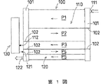
第1図はこの発明の第1実施形態のレシーバタンク付き熱交換器(凝縮器)を模式化して示す正面図である。同図に示すように、この熱交換器は、マルチフロータイプの熱交換器本体(100)と、レシーバタンク(130)とを備えている。
熱交換器本体(101)は、離間して対峙した左右一対の垂直方向に沿うヘッダー(101)(101)が設けられている。この一対のヘッダー(101)(101)間には、熱交換チューブとしての多数本の水平方向に沿う扁平チューブが、それらの両端を両ヘッダー(101)(101)に連通接続した状態で、上下方向に所定の間隔おきに並列状に配置される。更にヘッダー(101)内の所定位置には、仕切部材(102)が設けられ、これらの仕切部材(102)により、熱交換チューブが複数のパス(P1)〜(P5)に区分けされる。これらのパスのうち、パス(P1)〜(P3)により凝縮部(110)が構成されるとともに、パス(P4)(P5)により、凝縮部(110)に対し独立する過冷却部(120)が構成される。
ヘッダー(101)における凝縮部(110)の上下位置には、凝縮部入口(111)及び凝縮部出口(112)が設けられるとともに、一方のヘッダー(101)における過冷却部(120)の上下位置には、過冷却部入口(121)及び過冷却部出口(122)が形成されている。
第2図に示すように、レシーバタンク(130)は、縦長円筒形状のタンク本体(140)を具備し、そのタンク本体(140)の下壁として、出入口部材(150)が設けられている。
出入口部材(150)には、レシーバタンク入口(131)及び出口(132)が形成される。
更にタンク本体(140)内の下側半分には、モレキュラーシーブ等の球状粒子形状の乾燥剤が充填されて乾燥剤充填層(135)が形成されるとともに、タンク本体(140)内における乾燥剤充填層(135)よりも上方に、上部側空間(160)が形成されている。
また、タンク本体(140)内には、下端がレシーバタンク出口(132)に連通接続され、かつ上端が乾燥剤充填層(135)の上面における上部側空間(160)に開口された冷媒吸入管(133)がタンク本体(140)の軸心に沿って配置されている。
このレシーバタンク(130)のレシーバタンク入口(131)が、熱交換器本体(100)の凝縮部出口(112)に連通接続されるとともに、レシーバタンク出口(132)が過冷却部入口(121)にそれぞれ連通接続される。
このレシーバタンク付き熱交換器は、上記従来例と同様に、圧縮機、膨張弁等の減圧手段及び蒸発器と共に、自動車の空気調和用冷凍システムの凝縮器として用いられる。そして、この冷凍サイクルにおいて、圧縮機により圧縮された高温高圧のガス冷媒は、熱交換器本体(100)の凝縮部入口(111)から凝縮部(110)に流入される。
更に凝縮部入口(111)から凝縮部(110)に流入されたガス冷媒は、凝縮部(110)の各パス(P1)〜(P3)を順に流通する間に、外気との間で熱交換されて凝縮される。更にこうして凝縮された気液混合状態の冷媒は、凝縮部出口(112)を通ってレシーバタンク(130)内に導かれる。
レシーバタンク(130)内に導入された気液混合状態の冷媒は、レシーバタンク入口(132)からタンク本体(140)内の底部で急激に広域に拡散することで流速を低下させつつ、乾燥剤充填層(135)を上昇するとともに、乾燥剤充填層(135)が冷媒の上昇速度を低下させる抵抗層として機能する。従って、ガス冷媒に比べて流速の遅い液冷媒は、乾燥剤充填層(135)を低速で抜け出して上部側空間(160)に到達した際、十分に流速を落としていることから、該上部側空間(160)において乱れることなく、液溜まり(R)を生成していく。
また、ガス冷媒は、乾燥剤充填層(135)を上昇する過程において、急激に流速を低下させるため、上部側空間(160)に到達する液溜まり(R)に到達した際、穏やかな気泡として液中を上昇し、液面を乱すことなく気液界面においてスムーズに泡切れし、上方へ抜け出し、ガス冷媒として貯留されることになる。
このように乾燥剤充填層(135)の上方に、安定した液溜まり(R)が形成され、この液溜まり(R)の底面に、レシーバタンク出口(132)の流入側端部が開口しているため、液溜まり(R)の安定した液冷媒のみが出口(132)から流出されて、熱交換器本体(100)の過冷却部(120)に流入される。
こうして過冷却部(120)に流入された液冷媒は、第4及び第5パス(P4)(P5)を流通し、その間に、外気により過冷却された後、過冷却部出口(122)から流出されて、減圧手段、蒸発器及び圧縮機を順に流通し、こうして冷媒が、冷凍サイクル内を循環するものである。
以上のように、本実施形態のレシーバタンク付き熱交換器によれば、レシーバタンク(130)内に導入された凝縮冷媒が、低速で穏やかに液溜まり(R)を形成するとともに、効率良くスムーズに泡切れされるため、冷媒封入量の安定域を拡大でき、安定した液冷媒のみを確実に抽出することができる。このため、その液冷媒を過冷却部(120)に安定供給できるので、その過冷却部(120)において過冷却機能を最大限に発揮できて、十分な過冷却度を得ることができる。従って、冷凍サイクルを安定状態で運転でき、冷凍性能を向上させることができる。
更に液冷媒を安定供給できるため、レシーバタンク(130)の小型細径化及び高性能化、ひいては冷凍システム全体の小型軽量化及び高性能化を図ることができるとともに、省冷媒化を図ることができる。
なお、上記実施形態においては、抵抗層を乾燥剤充填層(135)により構成されているが、本発明はそれだけに限られず、抵抗層は、粒子状物が多数充填されたものや、多数の線状物を編織ないしは結着した織布や不織布からなるもの、多孔質部材や多孔板からなるもの等を単独又は積層したものの他に、これらを2種以上組み合わせたもの等により構成することができる。以下の実施形態及び変形例においても、抵抗層として同様の構成のものを用いることができる。
<第2実施形態>
第3図ないし第6図はこの発明の第2実施形態であるレシーバタンク付き熱交換器を示す図である。これらの図に示すように、このレシーバタンク付き熱交換器は、熱交換器本体(210)と、レシーバタンク(RD)とを備えている。
熱交換器本体(210)は、凝縮部(C)と過冷却部(S)とを一体化したサブクールシステムコンデンサであり、離間して対峙した左右一対の垂直方向に沿うヘッダー(211a)(211b)間に、多数本の水平方向に沿う偏平な熱交換チューブ(212)…が、それらの各両端を両ヘッダー(211a)(211b)に連通した状態で、上下方向に所定の間隔置きに並列状に配置されている。そして、熱交換チューブ(212)…の各間、ならびに最外側の熱交換チューブ(212)の外側にコルゲートフィン(213)が配され、更に最外側の熱交換チューブ(212)の外側にはコルゲートフィン(213)を保護するためのサイドプレート(214)が設けられている。
両ヘッダー(211a)(211b)の下側部における同じ高さ位置には、ヘッダー内部を仕切る仕切り部材(216)が設けられ、この仕切り部材(216)を境として上側が凝縮部(C)を構成すると共に、同下側が過冷却部(S)を構成している。また、凝縮部(C)においては、両ヘッダー(211a)(211b)の所定位置に設けられた複数の仕切部材(215)により、多数本の熱交換チューブ(212)…が第1ないし第3の流路(C1)〜(C3)に区分けされている。
更に、右側ヘッダー(211b)の上端部には凝縮部入口(217a)、同下端部には過冷却部出口(218b)、左側ヘッダー(211a)の凝縮部(C)に対応した下端部には凝縮部出口(217b)、同過冷却部(S)に対応した下端部には過冷却部入口(218a)がそれぞれ設けられている。
レシーバタンク(RD)は、縦型円筒形のタンク本体(201)内に、抵抗層としての乾燥剤充填層(202)が設けられ、その上部側と下部側とに空間(203)(204)を有しており、タンク本体(201)の下壁として出入口部材(201a)の中心から外れた位置に、下部側空間(204)に臨んで流出側端部(205a)を開口したレシーバタンク入口(205)が穿設されると共に、出入口部材(201a)の中心に軸心方向に貫通したレシーバタンク出口(206b)が形成されている。出入口部材(201a)におけるレシーバタンク出口(206b)には、吸入管(260)の下端が連通状態に固定される。ここで本実施形態においては、レシーバタンク出口(206b)及び吸入管(260)とにより、冷媒流出路(206)が構成されている。
吸入管(260)は、乾燥剤充填層(202)の上端中央部に上部側空間(203)に臨んで開口した流入側端部(206a)から、タンク本体(201)の中心線に沿って垂下し、出入口部材(201a)のレシーバタンク出口(206b)に至るとともに、流入側端部(206a)側が上部側空間(203)に向けてラッパ状に開いた拡径部(261)に形成されている。また、乾燥剤充填層(202)は、上下の多孔板(221a)(221b)間に、球状粒子形状の乾燥剤(202a)…が装填されたものである。なお、乾燥剤充填層(202)の上部の多孔板(221a)と充填された乾燥剤(202a)…の頂部との間には、微細多孔質材からなるフィルター層(207)が介在されている。
このレシーバタンク(RD)の入口(205)の流入側端部(205b)は、熱交換器本体(210)における凝縮部出口(217b)に接続されている。また、レシーバタンク出口(206b)は、L字管(219)を介して過冷却部入口(218a)に連通接続されている。
上記構成のレシーバタンク付き熱交換器によれば、冷凍サイクルの圧縮機(CP)から吐出された高温高圧のガス冷媒は、第4図に示すように、熱交換器本体(210)の凝縮部入口(217a)より凝縮部(C)に流入し、第1ないし第3の流路(C1)〜(C3)を順次通過する過程で外気と熱交換して凝縮し,気液混合状態として凝縮部出口(217b)からレシーバタンク(RD)に流入し、このレシーバタンク(RD)内で気液分離し、その液冷媒が冷媒流出路(206)を通して過冷却部入口(218a)より過冷却部(S)へ入り、この過冷却部(S)で更に外気と熱交換して過冷却状態として過冷却部出口(218b)より次のサイクル部位(蒸発器側)へ送られる。
しかして、レシーバタンク(RD)においては、熱交換器本体(210)の凝縮部(C)より送られてくる気液混合状態の冷媒は、当初は大きな流速であるが、レシーバタンク入口(205)を通して下部側空間(204)に流入した際に広域に拡散し、これに伴って流速を低下され、次いで乾燥剤充填層(202)内を上昇するが、この充填層(202)が流れに対する抵抗層として機能するため、その上昇速度を更に著しく低下させて上部側空間(203)に流入する。特に、この実施形態の場合、乾燥剤充填層(202)中を上昇する冷媒は、球状粒子形状の乾燥剤(202a)…の間を通過する過程で頻繁に向きを変えて長い経路を辿ることになるから、流速が著しく低下すると共に、整流作用を受けて局所的な高速流も消滅し、全体的に均質な上昇流に転化する。またフィルター層(207)を通過する過程でも、液冷媒及びガス冷媒は細かく分断されることになる。
しかして、気体に比べて流速の遅い液体は、該充填層(202)を抜けて上部側空間(203)に達した際、充分に流速を落としていることから、該上部側空間(203)で乱れることなく液溜まり(R)を生成してゆく。また、気体は、やはり乾燥剤充填層(202)内を上昇する過程で急激に流速を低下させるため、上部側空間(203)に生成する液溜まりに達した際、穏やかな気泡(B)として液中を上昇し、液面を乱すことなくスムーズに泡切れし、気液界面の上方へ抜け出してガス冷媒として溜まる。従って、生成する液溜まり(R)の液面(F)は変動が少なく非常に安定したものとなる。
一方、冷媒流出路(206)の流入側端部(206a)は上部側空間(203)内で安定して存在する液溜まり(R)の底に開口しているから、該液溜まり(R)の液冷媒のみが端部(206a)から冷媒流出路(206)内に流入し、過冷却部(S)へ安定供給される。このとき、冷媒流出路(206)の流入側端部(206a)側の拡径部(261)が乾燥剤充填層(202)上で凹所をなすから、液冷媒が冷媒流出路(206)へ流れ込み易くなると共に、この拡径部(261)での流速は冷媒流出路(206)の内奥側(非拡径部)よりも遅くなるため、ガス冷媒の気泡(B)が流入側端部(206a)に紛れ込んでも、拡径部(261)に存在する間において上方へ抜け出し易くなり、もって冷媒流出路(206)から導出される液冷媒は気泡(B)の巻き込みが非常に少ないものとなる。
従って、過冷却部(S)では過冷却機能を最大限に発揮でき、もって充分な過冷却領域を確保できる。また、このようなレシーバタンク(RD)を有する冷凍サイクルにおいては、冷媒封入量を早い段階で適正量に設定することが可能になると共に、タンク本体(201)内の余剰空間を緩衝空間として利用して最適冷媒点から過剰点までの間の安定域を拡大でき、もって非常に安定した運転を行える上、冷凍サイクルの稼働圧力も低く抑えられることから、必要な動力も低減され、システムの成績係数の改善を期待できる。
上記の作用は、前述した第8図のチャージ試験による凝縮冷媒の過冷却度と冷媒封入量との相関特性で言えば、過冷却度が上昇し始めてからシャープな立ち上がりで、冷媒封入量の少ない側で定常開始点に達し、定常域の幅が広くなることであり、図中の仮想線で示す理想的な曲線X2に近付くことを意味する。従って、この熱交換器を用いた自動車用エアコンでは、冷媒封入量の削減による小型化が容易であり、また負荷変動に対する性能の安定性が向上すると共に、継続走行に伴う経時的な性能低下を効果的に抑制できる。
また、本実施形態の熱交換器は、従来の冷凍サイクルにおける熱交換器に比較してレシーバタンクの冷媒導出入路の構成が僅かに異なるだけであるから、過冷却部を含めて既存の凝縮器をそのまま使用できる。またレシーバタンクについても、従来のレシーバードライヤー型のレシーバタンクの基本的な構造に大幅な改変を加える必要がない上、乾燥剤充填層(202)自体が整流機能を発揮するから、整流板等の格別な整流手段を省略でき、コスト的に有利である。
なお、上記実施形態におけるレシーバタンク(RD)の冷媒流出路(206)は拡径部(261)が上方へラッパ状に開く形になっているが、第7A図に示す変形例の拡径部(262)のように、冷媒流出路(206)の内奥側(非拡径部)に対して不連続に拡径した構造であってもよい。しかして、このような冷媒流出路(206)の流入側端部(206a)側の拡径による作用を効果的に発現させる上で、第6図及び第7A図に示すように、冷媒流出路(206)の非拡径部の内径をd1、拡径した流入側端部(206a)の開口径をd2、拡径部(261)(262)の深さをh1として、
d1<d2≦3d1で、且つd1<h1≦5d1
を満足するように設定することが推奨される。また、上記拡径部(261)(262)の深さh1は、乾燥剤充填層(202)の上下長さLd以下のものであること、即ち、h1≦Ldであることが望ましい。
第7B図は、レシーバタンク(RD)の更に他の変形例を示す。このレシーバタンク(RD)では、冷媒流出路(206)の拡径した流入側端部(206a)の開口周縁に気泡巻込み防止壁(208)が形成されていることから、上部側空間(203)内の液溜まり(R)中を上昇するガス冷媒の気泡(B)が流入側端部(206a)へ向かう液冷媒中に巻き込まれにくくなるから、冷媒流出路(206)から導出する液冷媒は気泡(B)の巻き込みがより少ないものとなる。
しかして、このような気泡巻込み防止壁(208)は、冷媒流出路(206)への液冷媒の流入を妨げることなく気泡の巻込み防止作用を発現させる上で、当該防止壁(208)の高さをh2、冷媒流出路(206)の前記内径をd1として、h2≦2d1となるように設定するのがよい。
更に、この発明に係るレシーバタンクにおいては、各部の寸法比率や配置構成は任意に設定できるが、レシーバタンク入口(205)の入側の中心と冷媒流出路(206)の流入側端部(206a)中心との平面視での距離をL1、タンク本体(201)の内径をD、レシーバタンク入口(205)の出側の開口径をφとして(第6図参照)、1.5φ≦L1≦0.8Dとなるように設定することが推奨される。すなわち、距離L1を上記範囲に設定すれば、レシーバタンク入口路(205)の出側中心と冷媒流出路(206)の流入側端部(206a)中心とが適度に離れているため、レシーバタンク入口(205)より導入された冷媒の上昇流が冷媒流出路(206)の流入側端部(206a)側へ集中せず、冷媒流速が充分に低下してより安定した冷媒液面を形成できる。
これに対し、上記の距離L1が近過ぎたり、レシーバタンク入口(205)が冷媒流出路(206)を取り囲む環状をなすような構成では、レシーバタンク入口(205)より導入された冷媒の上昇流が冷媒流出路(206)の流入側端部(206a)側へ集中し、冷媒流出路(206)近傍の冷媒流速が充分に低下せず、上部側空間(203)の液溜まり(R)は安定した冷媒液面を形成できなくなる。
なお、上記実施例ではタンク本体(201)内の乾燥剤充填層(202)の下方に下部側空間(204)を構成しているが、この下部側空間(204)を設けず、乾燥剤充填層(202)をタンク本体(201)の内底に達するものとして、レシーバタンク入口(205)からの冷媒が当該充填層(202)中に直接に流入する構成としてもよい。ただし、下部側空間(204)が存在すれば、レシーバタンク入口(205)から流入した冷媒の拡散が円滑になされ、この拡散による冷媒流速の低下作用がより大きくなるという利点がある。そして、この下部側空間(204)の上下幅を乾燥剤充填層(202)の上下長さの25%以下に設定すれば、乱流域を生じにくい上、大きな液溜まりを生成する余地がないから、上部側空間(203)への液冷媒の供給を充分に確保できる。また、下部側空間(204)には液冷媒及びガス冷媒の通過可能な抵抗体を充填してもよい。
一方、タンク本体(201)内の上部側空間(203)を液冷媒及びガス冷媒を溜めるに充分な大きさとする上で、乾燥剤充填層(202)の上下長さをLd、タンク本体(201)の有効上下長をLeとして、Ld≦0.7Leとすることが望ましい。なお、レシーバタンクを傾けた状態で使用する場合、冷媒流出路(206)は流入側端部(206a)がその傾斜状態でのタンク本体(201)内の中心より下位に来るように設定すればよい。
この発明に係る熱交換器は、上記実施形態のように過冷却部を有する冷凍サイクルに特に好適であるが、過冷却部のない種々の冷凍サイクルにも適用可能である。また、過冷却部については、上記実施形態のサブクールシステムコンデンサのように熱交換器本体と一体化した構造に限られず、独立した熱交換器として冷凍サイクルに組み込んだものでもよい。更に凝縮器についても、第3図及び第4図に例示した所謂パラレルフロー型熱交換器の他、熱交換管路として蛇行状のサーペンタインチューブを用いたもの等、様々な構造のものを使用することができる。
<第3実施形態>
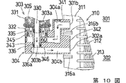
第9図はこの発明の第3の実施形態であるレシーバタンク付き熱交換器の一側部を示す正面図、第10図はその熱交換器のブロックフランジ周辺を拡大して示す一部切欠断面図、第11図はブロックフランジ周辺を分解して示す一部切欠断面図である。
これらの図に示すように、この熱交換器は、マルチフロータイプの熱交換器本体(310)と、レシーバタンク(303)と、レシーバタンク(303)を熱交換器本体(310)に接続するためのブロックフランジ(304)とを具備している。
熱交換器本体(310)は、離間して対峙した左右一対の垂直方向に沿うヘッダー(311)が設けられている。この一対のヘッダー(311)間には、熱交換チューブとしての多数本の水平方向に沿う扁平チューブ(312)が、それらの各両端を両ヘッダー(311)に連通接続した状態で、上下方向に所定の間隔おきに並列状に配置される。更に扁平チューブ(312)の各間、及び最外側の扁平チューブ(312)の外側には、コルゲートフィン(313)が配置されるとともに、最外側のコルゲートフィン(313)の外側には、帯板状サイドプレート(314)が設けられる。
熱交換器本体(310)における両ヘッダー(311)の同じ高さ位置には、仕切部材(316b)が設けられ、この仕切部材(316b)を境にして、上側の扁平チューブ(312)が凝縮部(301)として構成されるとともに、下側の扁平チューブ(312)が、上記凝縮部(301)に対し独立する過冷却部(302)として構成されている。
なお、各ヘッダー(311)には、凝縮部(301)及び過冷却部(302)のそれぞれの扁平チューブ(312)群を、複数のパスに区分けする仕切部材(316a)が設けられており、これにより、本実施形態の熱交換器本体(310)においては、上記第1図に示す第1実施形態と同様に、凝縮部(301)が第1ないし第3の3つのパスに区分けされるとともに、過冷却部(302)が第4及び第5の2つのパスに区分けされている。
熱交換器本体(310)の一方のヘッダー(311)における凝縮部(301)の下端位置には、凝縮部出口(301b)が形成されるとともに、図示しない他方側のヘッダーの上端部には、凝縮部入口が形成されている。更に一方のヘッダーにおける過冷却部(302)の上下両端位置には、過冷却部入口(302a)及び過冷却部出口(302b)がそれぞれ形成され、過冷却部出口(302b)には、出口管(321)の一端が連結固定されている。
この熱交換器本体(310)の凝縮部入口(図示省略)から流入されたガス冷媒は、凝縮部(301)を蛇行状に流通して一方のヘッダー(11)の凝縮部出口(301b)から流出される一方、その流通の間に冷媒が外気との熱交換により凝縮されるよう構成されている。
また過冷却部入口(302a)から流入された液冷媒は、過冷却部(302)を蛇行状に流通して、過冷却部出口(302b)及び出口管(321)を通って流出される一方、その流通の間に冷媒が外気によって過冷却されるよう構成されている。
レシーバタンク(303)は、縦長のタンク本体(331)からなり、そのタンク本体(331)の下壁が、出入口部材(332)により構成されている。
タンク本体(331)の上部外周には、ビーディング加工によって外周に突出する外向きフランジ状の押え凸部(331a)が形成されている(第9図参照)。
第10ないし第12図に示すように、出入口部材(332)は、その下面側に下方突出状に入口用凸段部(335)が形成されている。この凸段部(335)は円形の水平断面形状を有しており、軸心がレシーバタンク(303)の軸心に一致するよう構成されている。
更に入口用凸段部(335)の下面中央には、下方突出状に出口用凸段部(336)が形成されている。この凸段部(336)も円形の水平断面形状を有しており、軸心がレシーパタンク(3)の軸心に一致するよう構成されている。
また、出入口部材(332)における入口用凸段部(335)には、出口用凸段部(336)の外周に、上下方向に貫通してタンク本体(331)内に連通するレシーバタンク入口(33a)が周方向に所定間隔おきに4つ形成されている。更に出口用凸段部(336)の中央には、軸線に沿って上下方向に貫通してタンク本体(331)内に連通するレシーバタンク出口(303b)が形成されている。
ここで、4つのレシーバタンク入口(303a)の総開口面積は、レシーバタンク出口(303b)の開口面積よりも大きくなるように構成されている。
第9図ないし第14図に示すように、タンク本体(331)内には、冷媒吸入管(330)がその下端をレシーバタンク出口(303b)の内端に連通接続した状態で上下方向に沿って配置されている。なお、冷媒吸入管(330)の上端位置は、以下に説明する下部乾燥剤充填層(351)の上面よりも少し高い位置に設定されている。
タンク本体(331)内の下端には、冷媒吸入管(330)の外周に、多孔板(356)を介して、モレキュラーシーブ等の球状粒子形状の乾燥剤(5)が所定量充填されて、抵抗層としての下部乾燥剤充填層(351)が形成されるとともに、その乾燥剤充填層(351)の上面に、フィルター(355)を介して多孔板(357)が配置されている。
更にタンク本体(331)の内部における下部乾燥剤充填層(351)よりも上方には、上部側空間(354)が形成され、その上部側空間(354)の上部に、多孔板(358)が固定されるとともに、多孔板(358)の上方に、モレキュラーシーブ等の球状粒子形状の乾燥剤(305)が所定量充填されて、乾燥剤装填部材としての上部乾燥剤充填層(352)が形成されている。なお、上部乾燥剤充填層(352)は、本発明の抵抗層とは異なるものである。
このレシーバタンク(303)において、入口(303a)からタンク本体(331)内に流入された冷媒は、下部乾燥剤充填層(351)を透過上昇した後、上部側空間(354)において、液溜まり(R)を形成して、液冷媒のみが、冷媒吸入管(330)の上端から吸入されて、冷媒吸入管(330)を降下し、レシーバタンク出口(303b)から流出されるよう構成されている。
一方、第10図及び第11図に示すように、ブロックフランジ(304)は、凝縮部出口(301b)局辺に配置される第1ブロック(341)と、過冷却部入口(302a)周辺に配置される第2ブロック(343)と、レシーバタンク(303)の下端に配置される第3ブロック(343)とを一体に有するものであり、第1ブロック(341)の側面(接合面)が一方のヘッダー(311)における凝縮部出口(301b)周辺に接合固定されるとともに、第2ブロック(342)の側面(接合面)が一方のヘッダー(311)における過冷却部入口(302a)周辺に接合固定されている。
第3ブロック(343)は、その上面位置が凝縮部出口(301b)の形成位置よりも低く、過冷却部(302)の上部に対応する高さに設定されている。この第3ブロック(43)の上面には、上記レシーバタンク(3)の入口用凸段部(335)を適合し得る円形な水平断面形状の入口用凹段部(345)が形成されている。更に入口用凹段部(345)の底面には、レシーバタンク(303)の出口用凸段部(336)を適合し得る円形な水平断面形状の出口用凹段部(346)が形成されている。
ブロックフランジ(304)には、凝縮部出口(301b)及びレシーバタンク入口(303a)間を連通するための流入路(304a)と、レシーバタンク出口(303b)及び過冷却部入口(303a)間を連通するための流出路(304b)とが設けられている。
流入路(304a)は、その流入側端部が第1ブロック(341)における接合面に開口して凝縮部出口(301b)に連通接続されるとともに、中間領域が下方に向かって延び、流出側端部が第3ブロック(343)における入口用凹段部(345)の内周側面下端に開口されている。なお、この流入路(304a)の流出側端部開口は、入口用凹段部(345)の下端に位置しており、この位置は、凝縮部出口(301b)の形成位置よりも低く、過冷却部(302)の上部位置に相当する。
また流出路(304b)は、その流入側端部が第3ブロック(343)における出口用凹段部(346)の底面に開口されるとともに、流出側端部が第2ブロック(342)における接合面に開口して、過冷却部入口(302a)に連通接続されている。
このブロックフランジ(304)の出入口用凹段部(345)(346)に、レシーバタンク(303)の出入口用凸段部(335)(336)が適合状態に嵌め込まれる。このとき、出入口用凸段部(335)(336)の外周には、オーリング等のシール用リング(335a)(336a)が嵌着されており、シール用リング(336a)によって、出口用凹段部(346)内と、入口用凹段部(345)内との間の気密が図られるとともに、シール用リング(335a)によって、入口用凹段部(345)内と、外部との間の気密が図られるよう構成されている。
また入口用凹段部(345)の底部には、その底面とレシーバタンク入口(303a)の下端との間に隙間が設けられ、その隙間による液溜まり部(340)が形成されている。
一方、レシーバタンク(303)の上部を一方のヘッダー(311)に取り付けるためのブラケット(306)は、ブラケット本体(361)と、片側包囲片(362)とを有している。
第15図ないし第17図に示すように、ブラケット本体(361)は、レシーバタンク(303)のタンク本体(331)の片側半周に沿い得る平面視半円弧状の一方側包囲部(361a)を具備しており、この一方側包囲部(361a)の一端には、熱交換器本体(310)の一方のヘッダー(311)外面に沿い得る接合部(361b)が設けられている。また接合部(361b)の端部には、係合段部(361c)が形成されるとともに、接合部(361b)の端面には、ねじ切り孔(361d)が形成されている。更に一方側包囲部(361a)の他端には、レシーバタンク(303)の長さ方向に沿って上下に連続する溝状の軸取付孔(361e)が形成される。更に一方側包囲部(361a)の他端には、側方に延びる固定片(361f)が形成されるとともに、この固定片(361f)の先端部には、車体組付孔(361g)が形成されている。
このブラケット本体(361)の一方側包囲部(361a)を、レシーバタンク(303)のタンク本体(331)におけるフランジ状押え凸部(331a)の上面位置においてタンク本体(331)の後側半周を被覆するように配置した状態で、接合部(361b)を、熱交換器本体(310)の一方のヘッダー(311)の外面にろう付けすることにより、ブラケット本体(361)が一方のヘッダー(311)に固定される。
また、片側包囲片(362)は、ブラケット本体(361)の一方側包囲部(361a)に対し、タンク本体(331)の残り半周に沿い得る平面視半円弧状の他方側包囲部(362a)を具備している。この他方側包囲部(362a)の一端には、上記ブラケット本体(361)の係合段部(361c)に係合可能な係合突起(362c)が形成されるとともに、第9図及び第15図に示すようにブラケット本体(361)のねじ切り孔(361d)に対応して、上下方向に長い長孔形状のねじ挿通孔(362d)が形成されている。更に片側包囲片(362)の他端には、上下方向に連続し、かつブラケット本体(361)の軸取付孔(361e)に回転自在に挿入可能な軸部(362e)が形成されている。
この片側包囲片(362)の軸部(362e)をブラケット本体(361)の軸取付孔(361e)にその端部から挿入することにより、片側包囲片(362)をブラケット本体(361)に対し上下方向にスライド自在に、かつ軸部(362e)を支点に回転自在に取り付ける。そして、片側包囲片(362)を軸部(362e)を支点に回転させて、タンク本体(331)の前側半周部に沿わせるように配置した状態で、ねじ(365)をねじ挿通孔(362d)に挿通して、ねじ切り孔(361d)に締結することにより、片側包囲片(362)をブラケット本体(361)に固定するものである。
こうして取り付けられるブラケット(306)は、第9図に示すようにその包囲部(361a)(362a)が、タンク本体(331)のフランジ状押え凸部(331a)に上面に係止して、タンク本体(331)を下側に抑圧するように構成されている。
以上の構成のレシーバタンク付き熱交換器は、圧縮機、減圧手段及び蒸発器と共に、自動車の空気調和用冷凍システムの凝縮器として用いられる。そして、この冷凍サイクルにおいて、圧縮機により圧縮された高温高圧のガス冷媒は、凝縮部入口(図示省略)から凝縮部(301)に流入されて流通し、その間に、外気との間で熱交換されて凝縮された後、凝縮部出口(301b)から流出される。
凝縮部出口(301b)から流出された冷媒は、ブロックフランジ(304)の流入路(304a)を通って入口用凹段部(345)内に導かれ、その凹段部(345)の底部の液溜まり部(340)において液溜まりを形成する。
こうして液溜まり部(340)に貯留された液冷媒が、第13図及び第14図に示すように、レシーバタンク入口(303a)を通ってタンク本体(331)内に導かれ、水平方向に広域に拡散して上昇速度を低下させながら、下部乾燥剤充填層(351)を透過上昇していく。この上昇時において、下部乾燥剤充填層(351)が冷媒の流れに対し抵抗層として機能するため、冷媒は上昇速度を著しく低下させるとともに、冷媒は、多数の粒子状乾燥剤(305)の各間を通過して、長い経路を向きを変更しながら上昇することにより、整流作用を受けて局部的な高速流も消滅して偏流が防止され、全体的に均質な上昇流となって上部側空間(354)に流入される。
こうして上部側空間(354)に導入された液冷媒は、乱れることなく液溜まり(R)を形成していく。なお、下部乾燥剤充填層(351)を上昇する液冷媒に混入あるいは発生した気体(ガス冷媒)は、乾燥剤充填層(351)を上昇する際に急激に流速を低下させて、液溜まり(R)に到達した後、液中を上昇していき、液面を乱すことなくスムーズに泡切れし、気液界面の上方へ抜け出してガス冷媒として滞留する。
一方、液溜まり(R)の貯留する液冷媒のうち、底部に貯留する安定状態の液冷媒のみが、冷媒吸入管(330)に流入されて降下し、ブロックフランジ(304)の流出路(304b)を通って過冷却部(302)に導入される。
過冷却部(302)内に導入された液冷媒は、過冷却部(302)を流通しながら、外気により過冷却された後、過冷却部出口(302b)及び出口管(321)を通って流出されて、減圧手段、蒸発器及び圧縮機を順に流通し、こうして冷媒が、冷凍サイクル内を循環するものである。
以上のように、本実施形態のレシーバタンク付き熱交換器によれば、レシーバタンク(303)に導入された凝縮冷媒が、低速で穏やかに液溜まり(R)を形成するとともに、効率良くスムーズに泡切れされるため、冷媒封入量の安定域を拡大でき、安定した液冷媒のみを確実に抽出することができる。従って、その液冷媒を過冷却部(302)に安定供給することができるので、冷凍サイクルを安定状態で運転でき、優れた冷凍性能を得ることができる。更に安定域の拡大により液冷媒を安定供給できるため、レシーバタンク(303)の小型細径化及び高性能化、ひいては冷凍システム全体の小型軽量化及び高性能化を図ることができるとともに、省冷媒化を図ることができる。
ここで、本実施形態においては、下部乾燥剤充填層(351)の高さを「Ld」、タンク本体(331)の内直径を「D」としたとき、Ld<Dの関係が成立するよう構成するのが好ましい。
すなわち、高さ(Ld)が高過ぎる場合には、冷媒の液溜まり開始位置が高くなり、その分、冷媒封入量の少ない側での安定域開始点が高くなって、安定域が狭くなる恐れがあり、好ましくない。逆に高さ(Ld)が低過ぎる場合には、下部乾燥剤充填層(351)による上記抵抗機能や整流作用等を十分に得ることができず、安定した液冷媒を十分に抽出できない恐れがあり、好ましくない。
なお本実施形態においては、乾燥剤(305)を、下部乾燥剤充填層(351)と上部乾燥剤充填層(352)とに分割して設けているため、所定量の乾燥剤(305)を確実に得ることができ、冷媒の乾燥処理を十分に行うことができる。
また本実施形態においては、タンク本体(331)の内直径を「D」、レシーバタンク入口(303a)の中心と出口(303b)の中心との平面距離を「L1」、レシーバタンク入口(303a)の開口径を「φ」としたとき、1.5φ≦L1≦0.8Dの関係を成立させるのが望ましい。すなわち、距離(L1)を上記範囲に設定する場合には、レシーバタンク出口(303b)の中心と、入口(303a)の中心とが適度に離間するため、レシーバタンク入口(303a)から導入された冷媒の上昇流が、タンク内全域に均一に分散するようになり、中心側(レシーバタンク出口側)に偏るのを防止でき、冷媒流速を十分に低下させて、より安定した液冷媒を抽出することができる。これに対し、距離(L1)が近過ぎたり、遠過ぎたりする場合には、レシーバタンク入口(303a)から導入された冷媒が、タンク中心や、内周壁面に偏って分散せず、安定した液冷媒を抽出できない恐れがあり、好ましくない。
また本実施形態においては、ブロックフランジ(304)内における流入路(304a)の流出側端部に液溜まり部(340)を形成しているため、冷媒は液溜まり部(340)に一旦貯留されて、液冷媒のみがレシーバタンク入口(303a)を通ってタンク本体(331)内に導入される。このため、タンク本体(330)内へのガス冷媒の混入をより確実に防止することができ、レシーバタンク(330)によって、液冷媒の抽出を、より安定して行うことができ、冷凍性能を更に向上させることができる。
更に本実施形態においては、レシーバタンク入口(303a)の開口面積を、出口(303b)のそれよりも大きく形成しているため、レシーバタンク入口(303a)内で冷媒の流速を低下させることができ、冷媒中における気体の発生を防止することができるので、この点においても、泡切れ性を向上させることができ、より一層冷凍性能を向上させることができる。
しかも、レシーバタンク入口(303a)を、出入口部材(332)に周方向に所定の間隔おきに複数形成しているため、冷媒を、出入口部材(332)の周囲から分散させて均等にタンク本体(331)内に導入させることができ、冷媒の偏流、乱流等による気泡の発生等も有効に防止でき、なお一層冷凍性能を向上させることができる。
第18図はこの発明の第4実施形態である冷凍システム用レシーバタンクを模式化して示す断面図である。同図に示すように、この実施形態のレシーバタンク(303)においては、上記第13図の上部乾燥剤充填層(352)に代えて、モレキュラーシーブス等の粒子状乾燥剤(305)が網製袋部材等に装填されたパッケージタイプの乾燥剤装填部材(353)が、タンク本体(331)の上部側空間(354)に投入配置されて、液溜まり(R)に浮遊ないしは遊離状態に収容されるものである。
その他の構成は、上記第3実施形態と同様である。
この第4実施形態のレシーバタンク(303)においても、上記と同様に同様の効果を得ることができる。
第19図はこの発明の第5の実施形態である冷凍システム用レシーバタンク下部を模式化して示す断面図である。同図に示すように、この実施形態のレシーバタンク(303)においては、冷媒吸入管(330)の入側端部(上端部)が、上方にラッパ状に拡開形成された拡径部(330a)として構成されるとともに、拡径部(330a)の上端縁が、下部乾燥剤充填層(51)の上側に配置される多孔板(357)の上面と、同一高さ位置に設定されている。
その他の構成は、上記実施形態と同様である。
この第5実施形態のレシーバタンク(303)によれば、上記と同様の効果を奏する上更に、冷媒吸入管(330)の上端拡径部(330a)が、下部乾燥剤充填層(351)上で凹所として形成されるため、液冷媒が吸入管(330)へ流れ込み易くなるとともに、拡径部(330a)における流速が、吸入管(330)の非拡径部よりも遅くなるため、たとえガス冷媒が吸入管(330)に紛れ込んだとしても、拡径部(330a)を低速で流通する間に、ガス冷媒が上方へ抜け出すので、より一層確実に、液冷媒を安定供給することができる。
なお、冷媒吸入管(330)の拡径部(330a)は、必ずしもラッパ状に漸次拡径するような形状に形成する必要はなく、第20A図に示すように、非連続に拡径した構造であっても良い。
ここで、冷媒吸入管(330)の拡径部(330a)による上記の作用を効果的に発現させる上で、第19図及び第20A図に示すように、冷媒吸入管(330)の非拡径部の内径を「d1」、拡径部(330a)の開口径を「d2」、拡径部(330a)の深さを「h1」としたとき、d1<d2≦3d1、かつd1<h1≦5d1の関係が成立するように設定することが推奨される。
第20B図に他の変形例を示す。このレシーバタンク(303)では、冷媒吸入管(330)の上端拡径部(330a)における開口周縁に、気泡巻き込み防止壁(330b)が形成されるものである。
この変形例によれば、液溜まり(R)中を上昇するガス冷媒の気泡が、冷媒吸入管(330)の上端から吸引される液冷媒に巻き込まれるのを有効に防止でき、液冷媒の安定供給を、より一層確実に行うことができる。
ここで、気泡巻き込み防止壁(330b)は、レシーバタンク出口(303b)への液冷媒の流入を妨げることなく、気泡の巻き込み防止作用を発現させる上で、防止壁(330b)の高さを「h2」、冷媒吸入管(330)の内径を「d1」としたとき、h2≦2d1の関係が成立するように設定するのが良い。
なお、上記実施形態では、本発明を、熱交換器本体に過冷却部が形成されたレシーバタンク付き熱交換器、いわゆるザブクールシステムコンデンサに適用した場合を例に挙げて説明したが、本発明は、それだけに限られず、熱交換器本体に過冷却部が形成されないレシーバタンク付き熱交換器、例えばレシーバタンク付き凝縮器等の他、熱交換器に対し独立して配置されるレシーバタンクにも適用することができる。
<実施例>
第9図ないし第13図に示すレシーバタンク付き熱交換器が用いられた冷凍システムを実施例(X3)とし、その実施例の冷凍システムに対し、レシーバタンクとして図2に示すものを用いた以外は同じ構成の冷凍システムを実施例(X1)として、チャージ試験による凝縮冷媒の過冷却度(℃)と冷媒封入最(g)との関係を測定した。その結果を第21図のグラフに示す。
同グラフに示すように、実施例(X3)は、実施例(X1)に比べて、過冷却度が上昇し始めてからシャープな立ち上がりで、冷媒封入量の少ない側で安定域開始点(泡切れ点)に到達し、実施例(X3)の安定域(CA)が、実施例(X1)の安定域(CB)に比べて明らかに広くなっているのが判る。
具体的に述べると、実施例(X3)の泡切れ点は、約970gであり、実施例(X1)の泡切れ点(約1000g)に比べて、30g程度少なくなっていた。
なお、第18図に示す第4実施形態のレシーバタンクを用いた冷凍システムにおいて、上記と同様にチャージ試験を行ったところ、上記実施例(X3)とほぼ同じ結果が得られた。
この出願は、2000年8月11日付で出願された日本国特許出願特開2000−244199号の優先権主張を伴うものであり、その開示内容は、そのまま本願の一部を構成するものである。
ここで用いられた用語および説明は、この発明に係る実施形態を説明するために用いられたものであって、この発明はこれに限定されるものではない。この発明は請求の範囲であれば、その精神を逸脱するものではない限り、いかなる設計的変更も許容するものである。
産業上の利用可能性
以上のように、この発明に係る冷凍サイクル用レシーバタンク、レシーバタンク付き熱交換器及び冷凍サイクル用凝縮装置は、小型軽量化及び省冷媒化を図ることができる上、冷媒封入量に対する冷媒の安定域を広くできて、安定した液冷媒を次のサイクル部位に供給することができるものであるから、特にカーエアコン用冷凍サイクルとしての冷凍システムに好適に用いることができる。
【図面の簡単な説明】
第1図は、この発明の第1実施形態に係るレシーバタンク付き熱交換器を模式化して示す正面図である。
第2図は、第1実施形態に適用されたレシーバタンクを模式化して示す正面断面図である。
第3図は、この発明の第2実施形態に係るレシーバタンク付き熱交換器を示す正面図である。
第4図は、第2実施形態に係る熱交換器における冷媒の流れを模式的に示す正面断面図である。
第5図は、第2実施形態に適用されたレシーバタンクを示す断面図である。
第6図は、第2実施形態のレシーバタンクを模式化して示す断面図である。
第7A図は、第2実施形態の第1変形例に係るレシーバタンクの中央部の断面図である。
第7B図は、第2実施形態の第2変形例に係るレシーバタンクの中央部の断面図である。
第8図は、冷凍サイクルにおいて凝縮冷媒の過冷却度と冷媒封入量との関係を示すグラフである。
第9図は、この発明の第3実施形態であるレシーバタンク付き熱交換器の一側部を示す正面図である。
第10図は、第3実施形態の熱交換器におけるブロックフランジ周辺を拡大して示す正面断面図である。
第11図は、第3実施形態の熱交換器におけるブロックフランジ周辺を分解して示す正面断面図である。
第12図は、第3実施形態の熱交換器に適用されたレシーバタンクの出入口部材を示す下面図である。
第13図は、第3実施形態のレシーバタンクを模式化して示す断面図である。 第14図は、第3実施形態のレシーバタンクの下部を拡大して示す模式断面図である。
第15図は、第3実施形態の熱交換器におけるブラケット周辺を示す水平断面図である。
第16図は、第3実施形態に適用されたブラケットの本体を示す平面図である。
第17図は、第3実施形態に適用されたブラケットの片側包囲片を示す平面図である。
第18図は、この発明の第4実施形態である冷凍システム用レシーバタンクを模式化して示す正面断面図である。
第19図は、この発明の第5実施形態である冷凍システム用レシーバタンクの下部を模式化して示す正面断面図である。
第20A図は、第5実施形態における第1変形例としてのレシーバタンクの乾燥剤充填層上部周辺を示す断面図である。
第20B図は、第5実施形態における第2変形例としてのレシーバタンクの乾燥剤充填層上部周辺を示す断面図である。
第21図は、冷凍サイクルおいてチャージ試験による凝縮冷媒の過冷却度と冷媒封入量との関係を示すグラフである。
第22図は、冷凍サイクルの冷媒回路図である。
第23A図は、第1従来例としてのレシーバタンクを模式化して示す断面図である。
第23B図は、第2従来例としてのレシーバタンクを模式化して示す断面図である。
第23C図は、第3従来例としてのレシーバタンクを模式化して示す断面図である。
第23D図は、第4従来例としてのレシーバタンクを模式化して示す断面図である。Technical field
The present invention relates to a refrigeration cycle receiver tank, a heat exchanger with a receiver tank, and a refrigeration cycle condensing device that are applied to automobile, household, and commercial air conditioning systems.
Background art
In an expansion valve type refrigeration cycle, which is a typical type of refrigeration cycle, as shown in FIG. 22, high-temperature and high-pressure gas refrigerant discharged from a compressor (CP) enters a condenser (CD), and the outside air After heat exchange and cooling to condensate liquid, it flows into the receiver tank (RT) mainly in the liquid phase state, and after complete gas-liquid separation, only the liquid refrigerant is derived and is rapidly discharged by the expansion valve (EV). The refrigerant is expanded under reduced pressure and introduced into the evaporator (EP) as a low-pressure and low-temperature mist-like refrigerant. In the course of flowing through the evaporator (EP), it takes away latent heat from the outside air and evaporates. ) And is sucked into the compressor (CP). The pear ground portion in the figure indicates the liquid refrigerant. The refrigerant flow rate is controlled by adjusting the opening of the expansion valve (EV) based on a signal from a thermal cylinder (SC) provided on the outlet side of the evaporator (EP).
By the way, in recent refrigeration cycles for automobiles and the like, the refrigerant condensed in the condenser (CD) is subcooled to a temperature several degrees lower to increase the heat radiation amount, and then the expansion valve (EV), evaporation A technique has been proposed that attempts to improve the refrigeration capacity by introducing it to a container (EP). As this proposed technology, there is a method of providing a subcooling section that supercools the refrigerant that has been condensed by the condenser (CD) to a temperature that is several degrees lower than the condensation temperature, and sends it to the evaporator side in a stabilized state as a liquid refrigerant. It has been adopted. Normally, this subcool portion is arranged on the downstream side of the receiver tank (RT), but from the viewpoint of space efficiency, a configuration (subcool system condenser) that is integrated into the condenser (CD) is often employed.
On the other hand, as the receiver tank (RT), a so-called receiver dryer provided with a function of adsorbing and removing mixed water in the refrigerant by providing a desiccant packed layer therein is widely used. In such a receiver tank, as shown in FIGS. 23A to 23C, a sandwich type having spaces (33) (34) above and below a desiccant-filled layer (32) provided in a vertical tank (31). Alternatively, there is a bag type in which a desiccant-filled layer (32) is arranged on one side in a vertical tank (31) as shown in FIG. 23D.
FIG. 23A shows a suction pipe type receiver tank. The refrigerant flowing into the upper space (33) from the top refrigerant inlet (35) passes through the desiccant packed bed (32) and passes through the lower space ( 34), where the liquid refrigerant separated into the gas and liquid is led out from the top refrigerant outlet (37) through the suction pipe (36). FIG. 23B shows a supply pipe type receiver tank, and the refrigerant introduced from the refrigerant inlet (35) at the bottom flows into the upper space (33) through the supply pipe (38), and is filled with the desiccant filling layer. The liquid refrigerant that has permeated (32) and entered the lower space (34) where the gas and liquid are separated is led out from the refrigerant outlet (37) at the bottom. Further, FIG. 23C shows an inlet / outlet-type receiver tank, and the refrigerant that has flowed into the upper space (33) from the refrigerant inlet (35) at the top passes through the desiccant packed bed (32) and passes through the lower space ( 34), where the liquid refrigerant separated into gas and liquid is led out from the refrigerant outlet (37) at the bottom.
In the bag-type receiver tank of FIG. 23D, the refrigerant flowing in from the side refrigerant inlet (35) contacts the desiccant packed bed (32), and the liquid refrigerant separated at the bottom is the refrigerant outlet at the bottom. (37).
Conventionally, in an air conditioning system, improvement in space efficiency and high performance have always been issues. In particular, in an air conditioner for automobiles, there is a demand for downsizing the entire system in order to effectively use the limited space of the vehicle body as much as possible. For this purpose, it is necessary to reduce the amount of refrigerant enclosed in the refrigeration cycle. On the other hand, it is required to improve the stability of performance against load fluctuations (overcharge toughness) and to suppress the deterioration of performance over time (decrease of leakage toughness) associated with continuous running. It is desirable to secure as wide a stable range as possible in the supercooled state of the refrigerant with respect to the amount of the enclosed liquid.
However, when a charge test (cycle bench) of an air conditioner for automobiles is performed, in the correlation characteristic diagram between the degree of supercooling of the condensed refrigerant and the amount of refrigerant charged in FIG. Ideally, it should have a wide steady range with a sharp rise like the curve X2 indicated by the line. However, in a conventional air conditioner for a vehicle using a subcool system capacitor, the steady state is indicated by the curve Y indicated by the solid line in the figure. It is recognized that the rise of the curve until reaching the region is gentle, the steady start point shifts to the larger amount of refrigerant filling, and accordingly, the refrigerant filling point becomes slower and the width of the steady region becomes narrower. ing. This means that in conventional air conditioners for automobiles, it is difficult to reduce the size by reducing the amount of refrigerant, and the stability of the performance against load fluctuations is poor, and it is easy to cause a decrease in performance over time due to continuous running. is doing.
Under such a technical background, the present inventor first examined the cause of the problem in the conventional automotive air conditioner from various angles in order to realize miniaturization and high performance of an air conditioning system such as an automotive air conditioner. Went. As a result, one of the causes of the problem is the structure of the conventional general-purpose receiver tank (RT), and the gas-liquid interface near the refrigerant outlet (34), that is, the liquid level of the refrigerant is difficult to stabilize. It has been found that in addition to the stable supply to the site, a large amount of gas refrigerant is mixed in the liquid refrigerant to be derived, and as a result, the steady region is narrowed and the steady start point is shifted to the side with the larger refrigerant filling amount. .
That is, since the flow rate of refrigerant flowing into the receiver tank (RT) from the condenser (CD) side is generally large, a large turbulent flow region of liquid refrigerant is generated in the upper space (33) into which the refrigerant flows in the sandwich type. As a result, liquid refrigerant accumulates in the upper side space (33), so that the liquid refrigerant is not sufficiently supplied to the lower side space (34), and a little liquid in the lower side space (34). The reservoir is disturbed by the high-speed liquid flow that has passed through the desiccant packed bed (32), and gas refrigerant bubbles are generated at the same time. The gas refrigerant flows out from the refrigerant outlet (37) exposed in the gas phase due to large liquid level fluctuations. Or a large amount of bubbles entrained in the liquid refrigerant to be derived. On the other hand, in the bag type receiver tank, the refrigerant flow rate in the vicinity of the refrigerant outlet (37) becomes more unstable because the refrigerant flow rate in the interior is larger than that in the sandwich type receiver tank, and the turbulence in the flow is large. It is considered that the refrigerant flows out more easily.
The present invention has been made in view of the above-described technical background, and one of its purposes is to reduce the size and weight and save refrigerant, and to increase the stable range of refrigerant with respect to the amount of refrigerant charged. An object of the present invention is to provide a refrigeration cycle receiver tank capable of supplying a stable liquid refrigerant to the next cycle portion.
Other objects of the present invention will become apparent from the embodiments of the present invention described below.
Disclosure of the invention
The first one of the present invention (hereinafter referred to as “first invention” in this section) is a receiver tank for a refrigeration cycle in which condensed refrigerant is introduced and stored, and only liquid refrigerant flows out. A tank body provided with a refrigerant inflow inlet and a refrigerant outflow outlet on the lower wall, and a resistance layer that reduces the flow velocity of the refrigerant by permeation of the refrigerant is formed in the tank body, and an upper side space is formed above the tank A suction pipe having an upper end opened to the upper space and a lower end communicating with the refrigerant outlet is provided in the tank main body, from the refrigerant inlet The refrigerant that has flowed into the tank body passes upward through the resistance layer to form a liquid pool in the upper space, and the liquid refrigerant in the liquid pool flows out of the refrigerant through the suction pipe. Outlet It is characterized by comprising configured to be al outflow.
According to the first aspect of the present invention, the condensed refrigerant in the gas-liquid mixed state is rapidly diffused in a wide area at the bottom of the tank body immediately after flowing into the tank body from the refrigerant inflow inlet, thereby reducing the flow velocity. And then the resistive layer is raised to further reduce the flow rate. Therefore, the liquid refrigerant having a slower flow rate than the gas refrigerant, when passing through the resistance layer and reaching the upper space, has sufficiently reduced the flow velocity, and thus the liquid pool is generated without being disturbed in the upper space. To go. On the other hand, the gas refrigerant, like the liquid refrigerant, decreases the flow rate in the process of rising the resistance layer, so when it reaches the liquid pool generated in the upper space, it becomes a gentle bubble and rises in the liquid, Without disturbing the liquid level, bubbles are smoothly blown off at the gas-liquid interface, escapes upward, and is stored as a gas refrigerant.
Further, since the upper end of the suction pipe opens into a stable liquid pool in the upper space, only the liquid refrigerant in the liquid pool flows out from the refrigerant outlet outlet through the inlet pipe.
Thus, in the receiver tank of the present invention, since only stable liquid refrigerant can flow out, it becomes possible to set the refrigerant filling amount in the refrigeration cycle to an appropriate filling amount at an early stage, and the excess space in the receiver tank can be used as a buffer space. Since the stable region between the optimum refrigerant point and the excess point can be expanded, the entire refrigeration cycle can be operated in a stable state.
In the first aspect of the present invention, a structure having a large number of dispersion channels for dispersing the refrigerant in the diameter expansion direction of the tank body can be suitably employed as the resistance layer. For example, as the resistance layer, a layer filled with a large number of particulates, a woven or non-woven fabric obtained by knitting or binding a large number of linear objects, a porous member or a porous plate, or the like are laminated alone or in layers. In addition to those, a combination of two or more of these can be suitably employed.
In the first aspect of the invention, it is preferable that the resistance layer is constituted by a desiccant-filled layer filled with a number of particulate desiccants.
That is, in the receiver tank for the refrigeration cycle, a desiccant is incorporated in order to remove moisture in the refrigerant. However, in the case of the above configuration, the resistance layer can also be used as the desiccant.
Furthermore, in the first aspect of the invention, a configuration is adopted in which a lower side space for diffusing the refrigerant flowing in from the refrigerant inflow inlet in the radial direction is provided below the resistance layer in the tank body. It is preferable to do this.
In other words, when this configuration is adopted, the refrigerant flowing from the refrigerant inflow inlet diffuses in a wide area in the lower space and can further reduce the flow velocity, so that turbulent flow is more reliably generated. And a stable liquid pool can be generated smoothly in the upper space.
Further, in the present invention, it is preferable to adopt a configuration in which the vertical length of the lower side space is set to 25% or less with respect to the vertical length of the resistance layer.
That is, when this configuration is adopted, the lower side space can be made small while ensuring the above-described flow velocity lowering effect by the lower side space, so that a turbulent flow region is hardly generated and the liquid refrigerant is sufficiently supplied to the upper side space. Can be done.
In the first aspect of the invention, it is desirable to adopt a configuration in which the diameter of the upper end of the suction pipe is enlarged to form an enlarged diameter portion.
That is, when this configuration is adopted, the inlet side of the suction pipe becomes a recess in the upper part of the resistance layer, so that the liquid refrigerant can easily flow into the suction pipe, and the flow rate of the liquid refrigerant in the enlarged diameter portion is Since it becomes later than the non-expanded portion on the back side, even if the bubbles of the gas refrigerant are mixed into the expanded portion, the bubbles come out upward at the expanded portion.
Furthermore, in order to effectively express the action by the enlarged diameter portion, it is preferable to adopt the following configuration in the first invention.
That is, in the first aspect of the invention, d1 <d2 ≦ 3d1 and d1 <h1 where “d1” is the inner diameter of the non-expanded portion in the intermediate region of the inflow pipe and “d2” is the opening diameter of the expanded portion. It is preferable to adopt a configuration in which the relationship of ≦ 5d1 is established.
In the first aspect of the invention, it is preferable to adopt a configuration in which a bubble entrainment prevention wall extending upward is formed at the periphery of the upper end opening of the inflow pipe.
That is, when this configuration is adopted, the bubbles of the gas refrigerant rising in the liquid pool in the upper space are less likely to be entrained in the liquid refrigerant toward the suction pipe due to the presence of the bubble entrainment prevention wall. It is possible to prevent infiltration into the suction pipe.
Furthermore, in order to effectively express the action of the bubble entrainment prevention wall, in the first invention, it is desirable to adopt the following configuration.
That is, in the first aspect of the invention, a configuration is adopted in which the relationship of h2 ≦ 2d1 is established, where the inner diameter of the intermediate region of the inflow pipe is “d1” and the height of the bubble entrainment prevention wall is “h2”. desirable.
In the first aspect of the invention, the distance between the center of the refrigerant outflow outlet and the center of the refrigerant inflow inlet in the plan view is “L1”, the inner diameter of the tank body is “D”, and the refrigerant inflow It is preferable to adopt a configuration in which the relationship of 1.5φ ≦ L1 ≦ 0.8D is established, where the opening diameter at the outflow side end of the inlet is “φ”.
That is, when this configuration is adopted, since the refrigerant inflow inlet and the refrigerant outflow outlet can ensure an appropriate distance, the upward flow of the refrigerant flowing in from the refrigerant inflow inlet becomes the refrigerant outflow outlet side, That is, it is possible to prevent the bias toward the suction pipe side, and it is possible to generate a more stable liquid pool.
Furthermore, in the first aspect of the present invention, a configuration is adopted in which the relationship of Ld ≦ 0.7Le is established, where the vertical length of the desiccant packed layer is “Ld” and the effective vertical length of the tank body is “Le”. Is good.
That is, when this configuration is adopted, a sufficient space can be secured for storing the liquid refrigerant and the gas refrigerant in the upper part of the tank body, and a more stable liquid refrigerant can be supplied.
In the first aspect of the invention, a configuration in which a filter layer is disposed on at least the upper surface of the desiccant-filled layer, or a structure in which perforated press plates are disposed on both upper and lower surfaces of the desiccant-filled layer is adopted. preferable.
That is, when this configuration is adopted, the filter layer or the perforated press plate imparts a rectifying action to the refrigerant passing through them, and the local high-speed flow disappears, and both the liquid refrigerant and the gas refrigerant are finely divided. The liquid pool in the upper space can be generated in a more stable state.
In the first aspect of the invention, the refrigerant outlet is provided at the center of the lower wall of the tank body, and a plurality of the refrigerant inlets are provided on the outer periphery of the refrigerant outlet. Good to do.
That is, when adopting this configuration, the refrigerant can be dispersed from the periphery of the lower wall of the tank body and introduced into the tank body, and the generation of bubbles due to refrigerant drift, turbulence, etc. can be effectively prevented, and further A liquid pool in a stable state can be formed. Furthermore, in the first invention, it is desirable to adopt a configuration in which the refrigerant inflow outlets are arranged at predetermined intervals along the circumferential direction.
That is, when this configuration is adopted, the refrigerant can be introduced into the tank body evenly from the periphery of the lower wall of the tank body, and generation of bubbles due to refrigerant drift, turbulence, etc. can be more reliably prevented, and further A liquid pool in a stable state can be formed reliably.
On the other hand, the second one of the present invention (hereinafter referred to as “second invention” in this section) is a receiver tank for a refrigeration cycle in which condensed refrigerant is introduced and stored, and only liquid refrigerant flows out. A tank body provided with a refrigerant inflow inlet and a refrigerant outflow outlet on a lower wall, and a resistance layer for reducing a flow rate of the refrigerant by permeation of the refrigerant in the tank body, and an upper space on the upper side In the tank body, a suction pipe having an upper end opened to the upper space and a lower end communicated with the refrigerant outlet is provided in the tank body. The desiccant loading member loaded with the desiccant is provided in a state of being separated from the resistance layer, and the refrigerant flowing into the tank body from the refrigerant inflow inlet permeates the resistance layer upward. And said To generate a puddle on the part side space, the liquid refrigerant in the liquid pool is one which is characterized by comprising configured to be flowing out of the refrigerant outflow outlet through the suction pipe.
According to the second invention, similar to the first invention, since only stable liquid refrigerant can flow out, the refrigerant filling amount in the refrigeration cycle can be set to an appropriate filling amount at an early stage, and the receiver tank can Since the surplus space can be used as a buffer space and the stable region between the optimum refrigerant point and the excess point can be expanded, the entire refrigeration cycle can be operated in a stable state.
In addition, since the desiccant loading member filled with the desiccant is provided in the upper space of the tank body, the desiccant removes the moisture of the refrigerant circulating in the tank body and contains the moisture. Good refrigerant can be discharged, and the entire refrigeration cycle can be operated in a more stable state.
In the second aspect of the invention, the resistance layer is made of a material filled with a large number of particulate matter, a woven or non-woven fabric formed by knitting or binding a large number of linear matters, a porous member or a porous plate. In addition to a single or layered one, a combination of two or more of these is suitably employed, such as a configuration having a number of dispersion channels for dispersing the refrigerant in the diameter expansion direction of the tank body. can do.
In the second invention, it is preferable that the resistance layer is composed of a desiccant-filled layer filled with a number of particulate desiccants.
That is, when this configuration is employed, a sufficient amount of desiccant can be reliably obtained by the desiccant as the resistance layer and the desiccant loading member.
In the second aspect of the invention, the desiccant loading member is disposed in a fixed state in the upper space, or the desiccant loading member is disposed in a free state in the upper space. The configuration can be suitably adopted.
In the second aspect of the invention, it is preferable to adopt a configuration in which the relationship of Ld <D is established, where the vertical length of the desiccant-filled layer is “Ld” and the inner diameter of the tank body is “D”. .
That is, when this configuration is adopted, a sufficient space can be secured for storing the liquid refrigerant and the gas refrigerant in the upper part of the tank body, and a more stable liquid refrigerant can be supplied.
Furthermore, in the second aspect of the invention, a configuration is adopted in which a lower side space for diffusing the refrigerant flowing in from the refrigerant inflow inlet in the radial direction is provided below the resistance layer in the tank body. Good to do.
In other words, when this configuration is adopted, the refrigerant flowing from the refrigerant inflow inlet diffuses in a wide area in the lower space and can further reduce the flow velocity, so that turbulent flow is more reliably generated. And a stable liquid pool can be generated smoothly in the upper space.
In the second aspect of the invention, it is desirable to adopt a configuration in which a plurality of the refrigerant inflow outlets are provided on the outer periphery of the refrigerant outflow outlet.
That is, when adopting this configuration, the refrigerant can be dispersed from the periphery of the lower wall of the tank body and introduced into the tank body, and the generation of bubbles due to refrigerant drift, turbulence, etc. can be effectively prevented, and further A liquid pool in a stable state can be formed. Furthermore, in the second aspect of the invention, it is more preferable to employ a configuration in which the refrigerant inflow outlets are arranged at predetermined intervals along the circumferential direction.
That is, when this configuration is adopted, the refrigerant can be introduced into the tank body evenly from the periphery of the lower wall of the tank body, and generation of bubbles due to refrigerant drift, turbulence, etc. can be more reliably prevented, and further A liquid pool in a stable state can be formed reliably.
On the other hand, the receiver tank of the first invention can be integrally assembled with a heat exchanger such as a condenser to constitute a heat exchanger with a receiver tank.
That is, a third one of the present invention (hereinafter referred to as “third invention” in this section) includes a pair of headers arranged in parallel at intervals, and a plurality of heat exchange tubes in which both ends are connected to both headers. And a heat exchanger main body having a condensing part outlet for flowing out the condensed refrigerant passing through the heat exchange tube, a receiver tank inlet and a receiver tank outlet on the bottom wall, and from the receiver tank inlet A receiver tank that stores the flowed-in refrigerant and flows out only the liquid refrigerant from the receiver tank outlet, and a refrigerant path for introducing the refrigerant that has flowed out from the condenser outlet into the receiver tank inlet, In the receiver tank, a resistance layer for reducing the flow rate of the refrigerant by permeation of the refrigerant is provided in an aspect in which an upper space is formed on the upper side, and the receiver A suction pipe having an upper end open to the upper space and a lower end communicating with the receiver tank outlet, and the refrigerant flowing into the receiver tank from the receiver tank inlet, It is configured to pass through the resistance layer upward to form a liquid pool in the upper space, and to allow the liquid refrigerant in the liquid pool to flow out from the receiver tank outlet through the suction pipe. It is characterized by that.
In the third aspect of the invention, the resistive layer is constituted by a desiccant-filled layer filled with a large number of particulate desiccants, or the receiver tank is provided under the resistive layer in the receiver tank. It is preferable to employ one provided with a lower side space for diffusing the refrigerant flowing in from the tank inlet in the radial direction.
Further, the receiver tank of the first invention can be integrally assembled with a heat exchanger having a condensing part and a supercooling part to constitute a heat exchanger with a receiver tank such as a subcool system condenser.
That is, the fourth one of the present invention (hereinafter referred to as “fourth invention” in this section) includes a pair of headers arranged in parallel at intervals, and a plurality of heat exchange tubes in which both ends are connected to both headers. And a partition member for partitioning the insides of the headers to divide the plurality of heat exchange tubes into a condensing unit and a supercooling unit, and a condensing for flowing out the condensed refrigerant after passing through the condensing unit A heat exchanger main body having a part outlet and a supercooling part inlet for allowing the refrigerant to flow into the supercooling part, a receiver tank inlet and a receiver tank outlet on the bottom wall, and flowed from the receiver tank inlet A receiver tank that stores the refrigerant and flows out only the liquid refrigerant from the receiver tank outlet, and introduces the refrigerant that has flowed out of the condenser outlet into the receiver tank inlet, A refrigerant path for introducing the refrigerant flowing out from the receiver tank outlet into the supercooling section inlet, and a resistance layer for reducing the flow rate of the refrigerant by permeation of the refrigerant in the receiver tank is located above the upper side The receiver tank inlet is provided with a suction pipe having an upper end opened to the upper space and a lower end communicating with the receiver tank outlet. The refrigerant that has flowed into the receiver tank from above passes through the resistance layer upward to form a liquid reservoir in the upper space, and the liquid refrigerant in the liquid reservoir passes through the suction pipe and passes through the receiver. It is configured to flow out from the tank outlet.
In this 4th invention, it is preferable to employ | adopt that the said resistance layer is comprised by the desiccant filling layer with which many particulate desiccants were filled.
The receiver tank of the second invention can be assembled integrally with a heat exchanger such as a condenser to constitute a heat exchanger with a receiver tank.
That is, the fifth aspect of the present invention (hereinafter referred to as “fifth aspect” in this section) includes a pair of headers arranged in parallel at intervals, and a plurality of heat exchange tubes in which both ends are connected to both headers. And a heat exchanger main body having a condensing part outlet for flowing out the condensed refrigerant passing through the heat exchange tube, a receiver tank inlet and a receiver tank outlet on the bottom wall, and from the receiver tank inlet A receiver tank that stores the flowed-in refrigerant and flows out only the liquid refrigerant from the receiver tank outlet, and a refrigerant path for introducing the refrigerant that has flowed out from the condenser outlet into the receiver tank inlet, In the receiver tank, a resistance layer for reducing the flow rate of the refrigerant by permeation of the refrigerant is provided in an aspect in which an upper space is formed on the upper side, and the receiver A suction pipe having an upper end opened to the upper space and a lower end communicating with the receiver tank outlet, and a desiccant loading member loaded with a desiccant is disposed in the upper space. It is provided in a state separated from the resistance layer, and the refrigerant flowing into the receiver tank from the receiver tank inlet permeates upward through the resistance layer to generate a liquid pool in the upper space. In addition, the liquid refrigerant in the liquid pool is configured to flow out from the receiver tank outlet through the suction pipe.
In the fifth aspect of the present invention, it is preferable that the resistance layer is composed of a desiccant-filled layer filled with a number of particulate desiccants.
Furthermore, in this 5th invention, the said desiccant loading member can employ | adopt the structure formed by arrange | positioning in the said upper side space in the fixed state or a free state.
In addition, the receiver tank of the second aspect of the present invention can be assembled integrally with a heat exchanger having a condensing part and a supercooling part to constitute a heat exchanger with a receiver tank such as a subcool system condenser.
That is, the sixth aspect of the present invention (hereinafter referred to as “seventh aspect” in this section) includes a pair of headers arranged in parallel at intervals, and a plurality of heat exchange tubes in which both ends are connected to both headers. And a partition member for partitioning the insides of the headers to divide the plurality of heat exchange tubes into a condensing unit and a supercooling unit, and a condensing for flowing out the condensed refrigerant after passing through the condensing unit A heat exchanger main body having a part outlet and a supercooling part inlet for allowing the refrigerant to flow into the supercooling part, a receiver tank inlet and a receiver tank outlet on the bottom wall, and flowed from the receiver tank inlet A receiver tank that stores the refrigerant and flows out only the liquid refrigerant from the receiver tank outlet, and introduces the refrigerant that has flowed out of the condenser outlet into the receiver tank inlet, A refrigerant path for introducing the refrigerant flowing out from the receiver tank outlet into the supercooling section inlet, and a resistance layer for reducing the flow rate of the refrigerant by permeation of the refrigerant in the receiver tank is located above the upper side A space is formed, and a suction pipe having an upper end opened to the upper space and a lower end connected to the receiver tank outlet is provided in the receiver tank. A desiccant loading member loaded with a desiccant is provided in a state separated from the resistance layer, and the refrigerant flowing into the receiver tank from the receiver tank inlet permeates the resistance layer upward. In addition, a liquid pool is generated in the upper space, and liquid refrigerant in the liquid pool is configured to flow out from the receiver tank outlet through the suction pipe. Characterized in that it comprises.
In the sixth aspect of the invention, it is preferable that the resistance layer is composed of a desiccant-filled layer filled with a number of particulate desiccants.
On the other hand, the receiver tank of the first invention can constitute a condensing device for a refrigeration cycle together with a condenser such as a header type condenser or a serpentine condenser.
That is, the seventh aspect of the present invention (hereinafter referred to as “seventh aspect” in this section) includes a condensing part for condensing the refrigerant, and a condensing part outlet for discharging the refrigerant condensed by the condensing part. And a receiver tank having a receiver tank inlet and a receiver tank outlet on the bottom wall, storing the refrigerant flowing in from the receiver tank inlet, and allowing only liquid refrigerant to flow out of the receiver tank outlet, A refrigerant path for introducing the refrigerant that has flowed out from the outlet of the condensing unit into the receiver tank inlet, and a resistance layer that reduces the flow rate of the refrigerant by permeation of the refrigerant in the receiver tank, on the upper side Provided in a mode in which a space is formed, and in the receiver tank, an upper end is opened to the upper side space, and a lower end is connected to the receiver tank outlet. The suction pipe is provided, and the refrigerant flowing into the receiver tank from the receiver tank inlet permeates the resistance layer upward to form a liquid pool in the upper space, and this liquid pool The liquid refrigerant is configured to flow out from the receiver tank outlet through the suction pipe.
In the seventh aspect of the invention, it is preferable that the resistance layer is constituted by a desiccant-filled layer filled with a number of particulate desiccants.
Further, the receiver tank of the second invention can constitute a condensing device for a refrigeration cycle together with a condenser such as a header type condenser or a serpentine condenser.
That is, the eighth aspect of the present invention (hereinafter referred to as “the eighth aspect” in this section) includes a condensing unit for condensing the refrigerant, and a condensing unit outlet for discharging the refrigerant condensed by the condensing unit. And a receiver tank having a receiver tank inlet and a receiver tank outlet on the bottom wall, storing the refrigerant flowing in from the receiver tank inlet, and allowing only liquid refrigerant to flow out of the receiver tank outlet, A refrigerant path for introducing the refrigerant that has flowed out from the outlet of the condensing unit into the receiver tank inlet, and a resistance layer that reduces the flow rate of the refrigerant by permeation of the refrigerant in the receiver tank, on the upper side Provided in a mode in which a space is formed, and in the receiver tank, an upper end is opened to the upper side space, and a lower end is connected to the receiver tank outlet. A suction pipe is provided, and a desiccant loading member loaded with a desiccant is provided in the upper space so as to be separated from the resistance layer, and flows into the receiver tank from the receiver tank inlet. The generated refrigerant permeates upward through the resistance layer to form a liquid pool in the upper space, and the liquid refrigerant in the liquid pool flows out from the receiver tank outlet through the suction pipe. It is characterized by comprising.
In the eighth aspect of the invention, it is desirable that the resistance layer is composed of a desiccant-filled layer filled with a number of particulate desiccants.
BEST MODE FOR CARRYING OUT THE INVENTION
<First Embodiment>
FIG. 1 is a front view schematically showing a heat exchanger (condenser) with a receiver tank according to a first embodiment of the present invention. As shown in the figure, the heat exchanger includes a multiflow type heat exchanger body (100) and a receiver tank (130).
The heat exchanger body (101) is provided with a pair of left and right headers (101) and (101) that face each other at a distance. Between the pair of headers (101) and (101), a number of flat tubes along the horizontal direction as heat exchange tubes are connected in the state where both ends communicate with both headers (101) and (101). They are arranged in parallel at predetermined intervals in the direction. Furthermore, a partition member (102) is provided at a predetermined position in the header (101), and the heat exchange tube is divided into a plurality of paths (P1) to (P5) by these partition members (102). Among these paths, the condenser (110) is constituted by the paths (P1) to (P3), and the supercooling part (120) independent of the condenser (110) is constituted by the paths (P4) and (P5). Is configured.
A condenser inlet (111) and a condenser outlet (112) are provided at the upper and lower positions of the condensing part (110) in the header (101), and the upper and lower positions of the supercooling part (120) in one header (101). Are formed with a supercooling section inlet (121) and a supercooling section outlet (122).
As shown in FIG. 2, the receiver tank (130) includes a vertically long tank body (140), and an inlet / outlet member (150) is provided as a lower wall of the tank body (140).
The inlet / outlet member (150) is formed with a receiver tank inlet (131) and an outlet (132).
Further, the lower half of the tank body (140) is filled with a desiccant in the form of spherical particles such as molecular sieves to form a desiccant-filled layer (135), and the desiccant in the tank body (140). An upper space (160) is formed above the filling layer (135).
Further, a refrigerant suction pipe having a lower end communicating with the receiver tank outlet (132) and having an upper end opened to the upper space (160) on the upper surface of the desiccant filling layer (135) in the tank body (140). (133) is disposed along the axis of the tank body (140).
The receiver tank inlet (131) of the receiver tank (130) is connected in communication with the condenser outlet (112) of the heat exchanger body (100), and the receiver tank outlet (132) is connected to the supercooler inlet (121). Are connected to each other.
This heat exchanger with a receiver tank is used as a condenser of an air conditioning refrigeration system of an automobile, together with a decompression means such as a compressor and an expansion valve, and an evaporator, as in the conventional example. In this refrigeration cycle, the high-temperature and high-pressure gas refrigerant compressed by the compressor flows into the condensing unit (110) from the condensing unit inlet (111) of the heat exchanger body (100).
Further, the gas refrigerant flowing into the condensing unit (110) from the condensing unit inlet (111) exchanges heat with the outside air while sequentially flowing through the paths (P1) to (P3) of the condensing unit (110). And condensed. Further, the condensed refrigerant in the gas-liquid mixed state is led into the receiver tank (130) through the condenser outlet (112).
The refrigerant in the gas-liquid mixed state introduced into the receiver tank (130) rapidly diffuses in a wide area from the receiver tank inlet (132) to the bottom of the tank body (140), thereby reducing the flow rate, and the desiccant. While raising the packed bed (135), the desiccant packed bed (135) functions as a resistance layer that reduces the rising speed of the refrigerant. Therefore, since the liquid refrigerant having a slower flow rate than the gas refrigerant has sufficiently decreased the flow rate when it exits the desiccant packed bed (135) at low speed and reaches the upper space (160), The liquid reservoir (R) is generated without being disturbed in the space (160).
In addition, since the gas refrigerant suddenly decreases the flow velocity in the process of ascending the desiccant packed layer (135), when the gas refrigerant reaches the liquid reservoir (R) reaching the upper space (160), Ascending in the liquid, bubbles are smoothly blown off at the gas-liquid interface without disturbing the liquid surface, escapes upward, and is stored as a gas refrigerant.
Thus, a stable liquid reservoir (R) is formed above the desiccant-filled layer (135), and the inflow side end of the receiver tank outlet (132) is opened at the bottom of the liquid reservoir (R). Therefore, only the liquid refrigerant with a stable liquid reservoir (R) flows out from the outlet (132) and flows into the supercooling section (120) of the heat exchanger body (100).
The liquid refrigerant thus flowed into the supercooling section (120) flows through the fourth and fifth paths (P4) and (P5), and is supercooled by the outside air between them, and then from the supercooling section outlet (122). The refrigerant flows out through the decompression means, the evaporator, and the compressor in this order, and thus the refrigerant circulates in the refrigeration cycle.
As described above, according to the heat exchanger with a receiver tank of the present embodiment, the condensed refrigerant introduced into the receiver tank (130) gently forms a liquid pool (R) at a low speed, and is efficiently and smoothly. As a result, the stable range of the refrigerant filling amount can be expanded, and only a stable liquid refrigerant can be reliably extracted. For this reason, since the liquid refrigerant can be stably supplied to the supercooling section (120), the supercooling section (120) can exhibit the supercooling function to the maximum, and a sufficient degree of supercooling can be obtained. Therefore, the refrigeration cycle can be operated in a stable state, and the refrigeration performance can be improved.
Furthermore, since the liquid refrigerant can be stably supplied, the receiver tank (130) can be reduced in size and performance, and the refrigeration system as a whole can be reduced in size, weight, performance, and refrigerant can be saved. it can.
In the above-described embodiment, the resistance layer is configured by the desiccant-filled layer (135). However, the present invention is not limited to this, and the resistance layer may be one in which a large number of particles are filled or a number of wires. In addition to woven or non-woven fabrics that are knitted or bound, or a laminate of porous members or perforated plates, etc., or a combination of two or more of these materials can be used. . Also in the following embodiments and modifications, the same structure can be used as the resistance layer.
<Second Embodiment>
3 to 6 are views showing a heat exchanger with a receiver tank according to a second embodiment of the present invention. As shown in these drawings, the heat exchanger with a receiver tank includes a heat exchanger body (210) and a receiver tank (RD).
The heat exchanger body (210) is a subcool system condenser in which the condensing part (C) and the supercooling part (S) are integrated, and a pair of headers (211a) (211b) along a pair of left and right sides facing each other apart. ), A number of flat heat exchanging tubes (212) along the horizontal direction are arranged in parallel at predetermined intervals in the vertical direction with their both ends communicating with both headers (211a) (211b). Arranged in a shape. Further, corrugated fins (213) are arranged between the heat exchange tubes (212), and outside the outermost heat exchange tube (212), and further, a corrugate is arranged outside the outermost heat exchange tube (212). Side plates (214) are provided to protect the fins (213).
A partition member (216) for partitioning the inside of the header is provided at the same height position on the lower side of both headers (211a) and (211b), and the upper side of the partition member (216) defines the condensing part (C). While constituting, the lower side constitutes a supercooling section (S). Further, in the condensing part (C), a plurality of heat exchange tubes (212)... Are formed in the first to third by a plurality of partition members (215) provided at predetermined positions of both headers (211a) (211b). The flow paths (C1) to (C3) are divided.
In addition, the upper end of the right header (211b) has a condenser inlet (217a), the lower end has a subcooling outlet (218b), and the lower header corresponding to the condenser (C) of the left header (211a) A supercooling section inlet (218a) is provided at the lower end corresponding to the condensing section outlet (217b) and the supercooling section (S).
The receiver tank (RD) is provided with a desiccant filling layer (202) as a resistance layer in a vertical cylindrical tank main body (201), and a space (203) (204) between the upper side and the lower side thereof. A receiver tank inlet having an outflow side end (205a) facing the lower space (204) at a position off the center of the inlet / outlet member (201a) as a lower wall of the tank body (201) (205) is formed, and a receiver tank outlet (206b) penetrating in the axial direction is formed at the center of the inlet / outlet member (201a). The lower end of the suction pipe (260) is fixed in communication with the receiver tank outlet (206b) of the inlet / outlet member (201a). Here, in the present embodiment, the refrigerant outlet path (206) is constituted by the receiver tank outlet (206b) and the suction pipe (260).
The suction pipe (260) extends along the center line of the tank main body (201) from the inflow side end portion (206a) opened to the upper side space (203) at the upper end central portion of the desiccant packed bed (202). It hangs down and reaches the receiver tank outlet (206b) of the inlet / outlet member (201a), and the inflow side end (206a) side is formed in a diameter-enlarged portion (261) that opens in a trumpet shape toward the upper side space (203). ing. Further, the desiccant-filled layer (202) is obtained by loading spherical particle-shaped desiccants (202a)... Between upper and lower porous plates (221a) (221b). A filter layer (207) made of a fine porous material is interposed between the porous plate (221a) above the desiccant packed layer (202) and the top of the filled desiccant (202a). Yes.
An inflow side end (205b) of the inlet (205) of the receiver tank (RD) is connected to a condensing part outlet (217b) in the heat exchanger body (210). The receiver tank outlet (206b) is connected to the supercooling section inlet (218a) through an L-shaped pipe (219).
According to the heat exchanger with a receiver tank configured as described above, the high-temperature and high-pressure gas refrigerant discharged from the compressor (CP) of the refrigeration cycle is condensed in the heat exchanger body (210) as shown in FIG. It flows into the condensing part (C) from the inlet (217a), condenses by heat exchange with the outside air in the process of sequentially passing through the first to third flow paths (C1) to (C3), and condenses as a gas-liquid mixed state The refrigerant flows into the receiver tank (RD) from the section outlet (217b) and is separated into gas and liquid in the receiver tank (RD), and the liquid refrigerant passes through the refrigerant outflow passage (206) from the supercooling section inlet (218a). In (S), the supercooling section (S) further exchanges heat with the outside air to be in a supercooled state, and is sent from the supercooling section outlet (218b) to the next cycle part (evaporator side).
Thus, in the receiver tank (RD), the refrigerant in the gas-liquid mixed state sent from the condensing part (C) of the heat exchanger body (210) initially has a high flow rate, but the receiver tank inlet (205 ) Diffuses into the lower space (204) through a large area, and the flow velocity is reduced accordingly, and then rises in the desiccant packed bed (202). Since it functions as a resistance layer, its rising speed is further reduced and flows into the upper space (203). In particular, in the case of this embodiment, the refrigerant rising in the desiccant packed bed (202) frequently changes its direction in the process of passing between the spherical particle-shaped desiccants (202a), and follows a long path. Therefore, the flow velocity is remarkably lowered, and the local high-speed flow disappears due to the rectifying action, and the whole is converted into a homogeneous upward flow. Even in the process of passing through the filter layer (207), the liquid refrigerant and the gas refrigerant are finely divided.
Therefore, the liquid having a slower flow rate than the gas has sufficiently reduced the flow rate when it passes through the packed bed (202) and reaches the upper space (203), so that the upper space (203) The liquid reservoir (R) is generated without being disturbed by the. In addition, since the gas suddenly decreases the flow rate in the process of rising in the desiccant packed bed (202), when it reaches the liquid pool generated in the upper space (203), it becomes as gentle bubbles (B). It rises in the liquid, smoothly bubbles without disturbing the liquid surface, escapes above the gas-liquid interface, and accumulates as a gas refrigerant. Accordingly, the liquid level (F) of the generated liquid reservoir (R) is very stable with little fluctuation.
On the other hand, the inflow side end portion (206a) of the refrigerant outflow path (206) opens to the bottom of the liquid pool (R) that stably exists in the upper space (203). Only the liquid refrigerant flows into the refrigerant outflow passage (206) from the end (206a) and is stably supplied to the supercooling section (S). At this time, the enlarged diameter portion (261) on the inflow side end (206a) side of the refrigerant outflow passage (206) forms a recess on the desiccant packed bed (202), so that the liquid refrigerant flows into the refrigerant outflow passage (206). And the flow velocity at the expanded diameter portion (261) is slower than the inner depth side (non-expanded diameter portion) of the refrigerant outflow passage (206). Even if it is mixed in the portion (206a), it is easy to escape upward while it exists in the enlarged diameter portion (261), so that the liquid refrigerant led out from the refrigerant outflow passage (206) has very few bubbles (B). It becomes.
Therefore, in the supercooling section (S), the supercooling function can be maximized, and a sufficient supercooling region can be secured. Further, in the refrigeration cycle having such a receiver tank (RD), it is possible to set the refrigerant filling amount to an appropriate amount at an early stage, and the surplus space in the tank body (201) is used as a buffer space. As a result, the stable range from the optimum refrigerant point to the excess point can be expanded, so that the operation can be performed very stably and the operating pressure of the refrigeration cycle can be kept low. An improvement in coefficient can be expected.
In terms of the correlation between the degree of supercooling of the condensed refrigerant and the amount of refrigerant charged according to the charge test in FIG. 8 described above, the above-mentioned action is a sharp rise after the degree of supercooling starts to increase and the amount of refrigerant enclosed is small. The steady-state starting point is reached on the side, and the width of the steady-state area becomes wider, which means that the ideal curve X2 indicated by the phantom line in the figure is approached. Therefore, in an automotive air conditioner using this heat exchanger, it is easy to reduce the size by reducing the amount of refrigerant filled, improve the stability of the performance against load fluctuations, and reduce the performance over time associated with continuous running. It can be effectively suppressed.
In addition, the heat exchanger of the present embodiment is different from the heat exchanger in the conventional refrigeration cycle in that the configuration of the refrigerant lead-in / out path of the receiver tank is slightly different. The vessel can be used as it is. In addition, for the receiver tank, it is not necessary to make a major modification to the basic structure of a conventional receiver dryer type receiver tank, and the desiccant packed layer (202) itself exhibits a rectifying function. Special rectifying means can be omitted, which is advantageous in terms of cost.
In the above embodiment, the refrigerant outflow passage (206) of the receiver tank (RD) has an enlarged diameter portion (261) that opens upward in a trumpet shape, but the enlarged diameter portion of the modified example shown in FIG. 7A. As in (262), a structure in which the diameter is discontinuously expanded with respect to the inner back side (non-expanded diameter portion) of the refrigerant outflow passage (206) may be used. Thus, in order to effectively develop the effect of the diameter expansion on the inflow side end (206a) side of the refrigerant outflow path (206), as shown in FIGS. 6 and 7A, the refrigerant outflow path The inner diameter of the non-expanded portion of (206) is d1, the opening diameter of the expanded inflow side end portion (206a) is d2, and the depth of the expanded portions (261) and (262) is h1.
d1 <d2 ≦ 3d1 and d1 <h1 ≦ 5d1
It is recommended to set to satisfy Moreover, it is desirable that the depth h1 of the enlarged diameter portions (261) and (262) is not more than the vertical length Ld of the desiccant packed layer (202), that is, h1 ≦ Ld.
FIG. 7B shows still another modification of the receiver tank (RD). In this receiver tank (RD), since the bubble entrainment prevention wall (208) is formed at the opening peripheral edge of the inflow side end (206a) where the diameter of the refrigerant outflow passage (206) is increased, the upper side space (203) ) The gas refrigerant bubbles (B) rising in the liquid reservoir (R) are not easily caught in the liquid refrigerant toward the inflow side end (206a), so the liquid refrigerant derived from the refrigerant outflow passage (206). Is less entrained by bubbles (B).
Therefore, such a bubble entrainment prevention wall (208) can prevent the entrainment of bubbles without disturbing the inflow of the liquid refrigerant into the refrigerant outflow passage (206). It is preferable to set so that h2 ≦ 2d1, where h2 is the height of h2 and the inner diameter of the refrigerant outflow passage (206) is d1.
Further, in the receiver tank according to the present invention, the dimensional ratio and arrangement configuration of each part can be arbitrarily set, but the inlet side center of the receiver tank inlet (205) and the inflow side end (206a) of the refrigerant outflow passage (206). ) When the distance from the center in plan view is L1, the inner diameter of the tank body (201) is D, and the opening diameter on the outlet side of the receiver tank inlet (205) is φ (see FIG. 6), 1.5φ ≦ L1 ≦ It is recommended to set it to 0.8D. That is, if the distance L1 is set within the above range, the receiver tank inlet channel (205) and the outlet side center (206a) of the refrigerant outlet channel (206) are appropriately separated from each other. The upward flow of the refrigerant introduced from the inlet (205) does not concentrate on the inflow side end (206a) side of the refrigerant outflow path (206), and the refrigerant flow rate is sufficiently lowered to form a more stable refrigerant liquid level. .
On the other hand, in the configuration in which the distance L1 is too short or the receiver tank inlet (205) has an annular shape surrounding the refrigerant outflow path (206), the upward flow of the refrigerant introduced from the receiver tank inlet (205). Concentrate on the inflow side end (206a) side of the refrigerant outflow path (206), the refrigerant flow rate in the vicinity of the refrigerant outflow path (206) does not sufficiently decrease, and the liquid pool (R) in the upper space (203) A stable coolant liquid level cannot be formed.
In the above embodiment, the lower space (204) is formed below the desiccant packed layer (202) in the tank body (201). However, the lower space (204) is not provided, and the desiccant is filled. Assuming that the layer (202) reaches the inner bottom of the tank main body (201), the refrigerant from the receiver tank inlet (205) may flow directly into the packed bed (202). However, if the lower space (204) exists, there is an advantage that the refrigerant flowing from the receiver tank inlet (205) is smoothly diffused and the refrigerant flow rate lowering action due to this diffusion becomes larger. If the vertical width of the lower side space (204) is set to 25% or less of the vertical length of the desiccant packed bed (202), a turbulent flow region is hardly generated and there is no room for generating a large liquid pool. The supply of the liquid refrigerant to the upper space (203) can be sufficiently ensured. Further, the lower space (204) may be filled with a resistor through which liquid refrigerant and gas refrigerant can pass.
On the other hand, in order to make the upper side space (203) in the tank body (201) large enough to store liquid refrigerant and gas refrigerant, the vertical length of the desiccant packed bed (202) is Ld, and the tank body (201 It is desirable that Ld ≦ 0.7Le, where Le is the effective vertical length of. When the receiver tank is used in an inclined state, the refrigerant outflow path (206) should be set so that the inflow side end (206a) is positioned lower than the center in the tank body (201) in the inclined state. Good.
The heat exchanger according to the present invention is particularly suitable for a refrigeration cycle having a supercooling section as in the above embodiment, but can also be applied to various refrigeration cycles having no supercooling section. Further, the subcooling section is not limited to the structure integrated with the heat exchanger main body like the subcool system condenser of the above embodiment, but may be incorporated into the refrigeration cycle as an independent heat exchanger. In addition to the so-called parallel flow type heat exchanger illustrated in FIGS. 3 and 4, condensers having various structures such as those using serpentine serpentine tubes as heat exchange pipes are used. be able to.
<Third Embodiment>
FIG. 9 is a front view showing one side portion of a heat exchanger with a receiver tank according to a third embodiment of the present invention, and FIG. 10 is a partially cutaway cross section showing an enlarged view of the periphery of the block flange of the heat exchanger. FIG. 11 and FIG. 11 are partially cutaway sectional views showing the periphery of the block flange in an exploded manner.
As shown in these drawings, this heat exchanger connects a multi-flow type heat exchanger body (310), a receiver tank (303), and a receiver tank (303) to the heat exchanger body (310). And a block flange (304).
The heat exchanger body (310) is provided with a pair of headers (311) along a pair of left and right sides facing each other at a distance. Between this pair of headers (311), a large number of flat tubes (312) along the horizontal direction as heat exchange tubes are connected in the vertical direction with their respective ends communicating with both headers (311). They are arranged in parallel at predetermined intervals. Further, corrugated fins (313) are disposed between the flat tubes (312) and outside the outermost flat tube (312), and on the outer sides of the outermost corrugated fins (313), strips are provided. A side plate (314) is provided.
A partition member (316b) is provided at the same height position of both headers (311) in the heat exchanger body (310), and the upper flat tube (312) condenses with this partition member (316b) as a boundary. The lower flat tube (312) is configured as a supercooling section (302) independent of the condensing section (301).
Each header (311) is provided with a partition member (316a) that divides each flat tube (312) group of the condensing unit (301) and the supercooling unit (302) into a plurality of paths. Thereby, in the heat exchanger main body (310) of this embodiment, the condensing part (301) is divided into the 1st thru | or 3rd path | pass similarly to 1st Embodiment shown in the said FIG. At the same time, the supercooling section (302) is divided into the fourth and fifth passes.
At the lower end position of the condensing part (301) in one header (311) of the heat exchanger body (310), a condensing part outlet (301b) is formed, and at the upper end part of the other header not shown, A condenser inlet is formed. Furthermore, a supercooling portion inlet (302a) and a supercooling portion outlet (302b) are formed at both upper and lower end positions of the supercooling portion (302) in one header, and an outlet pipe is formed at the supercooling portion outlet (302b). One end of (321) is connected and fixed.
The gas refrigerant flowing in from the condenser inlet (not shown) of the heat exchanger body (310) flows in a meandering manner through the condenser (301) and from the condenser outlet (301b) of one header (11). On the other hand, the refrigerant is condensed during the circulation by heat exchange with the outside air.
The liquid refrigerant flowing in from the supercooling section inlet (302a) flows in a meandering manner through the supercooling section (302) and flows out through the supercooling section outlet (302b) and the outlet pipe (321). The refrigerant is supercooled by the outside air during the circulation.
The receiver tank (303) is composed of a vertically long tank body (331), and the lower wall of the tank body (331) is constituted by an inlet / outlet member (332).
On the outer periphery of the upper portion of the tank body (331), an outward flange-like presser convex portion (331a) protruding to the outer periphery by beading is formed (see FIG. 9).
As shown in FIGS. 10 to 12, the entrance / exit member (332) is formed with an entrance convex step (335) on the lower surface side thereof so as to protrude downward. This convex step portion (335) has a circular horizontal cross-sectional shape, and is configured such that the axis coincides with the axis of the receiver tank (303).
Further, an exit convex portion (336) is formed in a downward projecting shape at the center of the bottom surface of the convex portion for entrance (335). This convex step portion (336) also has a circular horizontal cross-sectional shape, and is configured such that the axis coincides with the axis of the receiver tank (3).
Also, the inlet convex portion (335) of the inlet / outlet member (332) has a receiver tank inlet (through the vertical direction of the outlet convex step (336) and communicated with the tank body (331) in the vertical direction. Four 33a) are formed at predetermined intervals in the circumferential direction. Furthermore, a receiver tank outlet (303b) that penetrates in the vertical direction along the axis and communicates with the tank main body (331) is formed at the center of the convex portion for outlet (336).
Here, the total opening area of the four receiver tank inlets (303a) is configured to be larger than the opening area of the receiver tank outlet (303b).
As shown in FIGS. 9 to 14, in the tank body (331), the refrigerant suction pipe (330) extends in the vertical direction with its lower end communicating with the inner end of the receiver tank outlet (303b). Are arranged. In addition, the upper end position of the refrigerant | coolant suction pipe (330) is set in the position a little higher than the upper surface of the lower desiccant filling layer (351) demonstrated below.
The lower end in the tank body (331) is filled with a predetermined amount of a desiccant (5) in the form of a spherical particle such as a molecular sieve on the outer periphery of the refrigerant suction pipe (330) via a porous plate (356), A lower desiccant-filled layer (351) as a resistance layer is formed, and a porous plate (357) is disposed on the upper surface of the desiccant-filled layer (351) via a filter (355).
Further, an upper space (354) is formed above the lower desiccant filling layer (351) inside the tank body (331), and a porous plate (358) is formed above the upper space (354). While being fixed, a predetermined amount of a spherical particle shaped desiccant (305) such as molecular sieve is filled above the perforated plate (358) to form an upper desiccant packed layer (352) as a desiccant loading member. Has been. The upper desiccant-filled layer (352) is different from the resistance layer of the present invention.
In the receiver tank (303), the refrigerant flowing into the tank main body (331) from the inlet (303a) permeates and rises through the lower desiccant filling layer (351), and then accumulates in the upper space (354). (R) is formed, and only the liquid refrigerant is sucked from the upper end of the refrigerant suction pipe (330), descends the refrigerant suction pipe (330), and flows out from the receiver tank outlet (303b). Yes.
On the other hand, as shown in FIG. 10 and FIG. 11, the block flange (304) is provided around the first block (341) disposed on the local side of the condenser outlet (301b) and the supercooling inlet (302a). It has the 2nd block (343) arrange | positioned, and the 3rd block (343) arrange | positioned at the lower end of the receiver tank (303) integrally, and the side surface (joining surface) of the 1st block (341) is The header (311) is joined and fixed around the condenser outlet (301b) and the side surface (joint surface) of the second block (342) is around the supercooling inlet (302a) of the header (311). Bonded and fixed.
The upper surface of the third block (343) is lower than the position where the condenser outlet (301b) is formed, and is set to a height corresponding to the upper part of the supercooling part (302). On the upper surface of the third block (43), an inlet concave step portion (345) having a circular horizontal cross-sectional shape capable of fitting the inlet convex step portion (335) of the receiver tank (3) is formed. . Further, the bottom surface of the inlet concave step (345) is formed with an outlet concave step (346) having a circular horizontal cross-sectional shape that can fit the outlet convex step (336) of the receiver tank (303). Yes.
The block flange (304) has an inflow path (304a) for communicating between the condenser outlet (301b) and the receiver tank inlet (303a), and between the receiver tank outlet (303b) and the subcooler inlet (303a). An outflow passage (304b) for communication is provided.
The inflow channel (304a) has an inflow side end portion that opens at a joint surface in the first block (341) and is connected to the condensing unit outlet (301b), and an intermediate region that extends downward, The end portion is opened at the lower end of the inner peripheral side surface of the inlet recessed step portion (345) in the third block (343). The outflow side end opening of the inflow channel (304a) is located at the lower end of the inlet recessed step (345), and this position is lower than the formation position of the condensing unit outlet (301b). It corresponds to the upper position of the cooling part (302).
The outflow channel (304b) has an inflow side end portion opened to the bottom surface of the outlet recessed step (346) in the third block (343) and an outflow side end portion joined to the second block (342). Open to the surface and communicated with the supercooling section inlet (302a).
The convex / concave steps (335) and (336) for the receiver tank (303) are fitted in the fitting state into the concave / convex steps (345) and (346) for the inlet / outlet of the block flange (304). At this time, sealing rings (335a) and (336a) such as O-rings are fitted on the outer periphery of the entrance / exit convex stepped portions (335) and (336), and the exit recess is formed by the sealing ring (336a). Airtightness is achieved between the inside of the step portion (346) and the inside of the recessed portion for entrance (345), and the inside of the recessed portion for entrance (345) and the outside are sealed by the sealing ring (335a). It is configured so that airtightness is achieved.
In addition, a gap is provided at the bottom of the inlet recess (345) between the bottom and the lower end of the receiver tank inlet (303a), and a liquid reservoir (340) is formed by the gap.
On the other hand, the bracket (306) for attaching the upper part of the receiver tank (303) to one header (311) has a bracket main body (361) and a one-side surrounding piece (362).
As shown in FIGS. 15 to 17, the bracket body (361) has a semicircular arc-shaped one-side surrounding portion (361a) that can be along a half circumference of the tank body (331) of the receiver tank (303). A joint portion (361b) that can be along the outer surface of one header (311) of the heat exchanger body (310) is provided at one end of the one-side surrounding portion (361a). In addition, an engagement step (361c) is formed at the end of the joint (361b), and a threaded hole (361d) is formed at the end of the joint (361b). Furthermore, a groove-shaped shaft attachment hole (361e) that is continuous in the vertical direction along the length direction of the receiver tank (303) is formed at the other end of the one-side surrounding portion (361a). Further, a laterally extending fixing piece (361f) is formed at the other end of the one side surrounding portion (361a), and a vehicle body assembly hole (361g) is formed at the distal end of the fixing piece (361f). Has been.
The one side surrounding portion (361a) of the bracket body (361) is arranged on the rear half of the rear side of the tank body (331) at the upper surface position of the flange-like pressing projection (331a) in the tank body (331) of the receiver tank (303). The joint (361b) is brazed to the outer surface of one header (311) of the heat exchanger body (310) in a state where the bracket body (361) is disposed so as to cover the bracket body (361). ).
In addition, the one-side surrounding piece (362) is a semicircular arc-shaped other-side surrounding portion (362a) that can be along the remaining half circumference of the tank body (331) with respect to the one-side surrounding portion (361a) of the bracket body (361). It has. An engagement protrusion (362c) that can be engaged with the engagement step portion (361c) of the bracket body (361) is formed at one end of the other-side surrounding portion (362a), and FIGS. As shown in the drawing, a long and long screw insertion hole (362d) is formed in the vertical direction corresponding to the threaded hole (361d) of the bracket body (361). Furthermore, the other end of the one-side surrounding piece (362) is formed with a shaft portion (362e) which is continuous in the vertical direction and can be rotatably inserted into the shaft mounting hole (361e) of the bracket body (361).
By inserting the shaft portion (362e) of the one-side surrounding piece (362) into the shaft mounting hole (361e) of the bracket main body (361) from the end thereof, the one-side surrounding piece (362) is inserted into the bracket main body (361). The shaft portion (362e) is attached to the fulcrum so as to be slidable in the vertical direction. Then, the screw (365) is inserted into the screw insertion hole (362d) in a state where the one-side surrounding piece (362) is rotated around the shaft portion (362e) and is arranged along the front half circumference of the tank body (331). ) And fastened to the threaded hole (361d), thereby fixing the one-side surrounding piece (362) to the bracket body (361).
As shown in FIG. 9, the bracket (306) attached in this way has its surrounding portions (361a) and (362a) locked on the upper surface of the flange-like presser convex portion (331a) of the tank body (331), so that the tank The main body (331) is configured to be suppressed downward.
The heat exchanger with a receiver tank having the above configuration is used as a condenser of an air conditioning refrigeration system of an automobile together with a compressor, a decompression unit, and an evaporator. In this refrigeration cycle, the high-temperature and high-pressure gas refrigerant compressed by the compressor flows into the condensing unit (301) from the condensing unit inlet (not shown) and circulates between them, and exchanges heat with the outside air. After being condensed, it flows out from the condensing part outlet (301b).
The refrigerant flowing out from the condenser outlet (301b) passes through the inflow passage (304a) of the block flange (304) and is guided into the inlet concave step (345), and is formed at the bottom of the concave step (345). A liquid reservoir is formed in the liquid reservoir (340).
The liquid refrigerant stored in the liquid reservoir (340) in this manner is guided into the tank body (331) through the receiver tank inlet (303a) as shown in FIGS. The lower desiccant-packed layer (351) is permeated and raised while diffusing to lower the rising speed. At this time, since the lower desiccant packed layer (351) functions as a resistance layer against the flow of the refrigerant, the refrigerant remarkably decreases the rising speed, and the refrigerant is separated from each of the many particulate desiccants (305). Passing through and ascending while changing the direction of the long path, the local high-speed flow disappears due to the rectifying action, and the uneven flow is prevented, so that the upper side becomes a uniform upward flow as a whole. It flows into the space (354).
The liquid refrigerant thus introduced into the upper space (354) forms a liquid pool (R) without being disturbed. Note that the gas (gas refrigerant) mixed or generated in the liquid refrigerant that rises in the lower desiccant packed bed (351) drastically decreases the flow rate when the desiccant packed bed (351) is lifted, and the liquid pool ( After reaching R), the liquid ascends and smoothly blows out without disturbing the liquid level, escapes above the gas-liquid interface and stays as a gas refrigerant.
On the other hand, out of the liquid refrigerant stored in the liquid reservoir (R), only the stable liquid refrigerant stored in the bottom flows into the refrigerant suction pipe (330) and descends, and the outflow path (304b) of the block flange (304). ) And introduced into the supercooling section (302).
The liquid refrigerant introduced into the supercooling section (302) is supercooled by the outside air while flowing through the supercooling section (302), and then passes through the supercooling section outlet (302b) and the outlet pipe (321). The refrigerant flows out through the decompression means, the evaporator, and the compressor in this order, and thus the refrigerant circulates in the refrigeration cycle.
As described above, according to the heat exchanger with a receiver tank of the present embodiment, the condensed refrigerant introduced into the receiver tank (303) forms a liquid pool (R) gently at a low speed, and efficiently and smoothly. Since the bubbles are blown out, the stable range of the refrigerant filling amount can be expanded, and only a stable liquid refrigerant can be reliably extracted. Therefore, since the liquid refrigerant can be stably supplied to the supercooling section (302), the refrigeration cycle can be operated in a stable state, and excellent refrigeration performance can be obtained. Furthermore, since the liquid refrigerant can be stably supplied by expanding the stable range, the receiver tank (303) can be reduced in size and performance, and the refrigeration system as a whole can be reduced in size, weight, and performance. Can be achieved.
Here, in this embodiment, when the height of the lower desiccant packed layer (351) is “Ld” and the inner diameter of the tank body (331) is “D”, the relationship of Ld <D is established. It is preferable to configure.
That is, when the height (Ld) is too high, the refrigerant pool start position becomes high, and accordingly, the stable region start point on the side where the refrigerant filling amount is small becomes high, and the stable region may be narrowed. Is not preferable. On the other hand, if the height (Ld) is too low, the above-mentioned resistance function and rectifying action by the lower desiccant-packed layer (351) cannot be sufficiently obtained, and stable liquid refrigerant may not be sufficiently extracted. Yes, not preferred.
In the present embodiment, since the desiccant (305) is divided into the lower desiccant filling layer (351) and the upper desiccant filling layer (352), a predetermined amount of desiccant (305) is provided. Thus, the refrigerant can be reliably obtained and the refrigerant can be sufficiently dried.
In this embodiment, the inner diameter of the tank main body (331) is “D”, the plane distance between the center of the receiver tank inlet (303a) and the center of the outlet (303b) is “L1”, and the receiver tank inlet (303a). It is desirable to establish the relationship of 1.5φ ≦ L1 ≦ 0.8D, where “φ” is the opening diameter. That is, when the distance (L1) is set to the above range, the center of the receiver tank outlet (303b) and the center of the inlet (303a) are appropriately separated from each other, and thus the distance (L1) is introduced from the receiver tank inlet (303a). The upward flow of the refrigerant is uniformly distributed throughout the tank, and can be prevented from being biased toward the center side (receiver tank outlet side), and the refrigerant flow rate is sufficiently reduced to extract more stable liquid refrigerant. be able to. On the other hand, when the distance (L1) is too close or too far, the refrigerant introduced from the receiver tank inlet (303a) is stable without being unevenly distributed to the center of the tank or the inner peripheral wall surface. The liquid refrigerant cannot be extracted, which is not preferable.
In the present embodiment, since the liquid reservoir (340) is formed at the outflow side end of the inflow channel (304a) in the block flange (304), the refrigerant is temporarily stored in the liquid reservoir (340). Thus, only the liquid refrigerant is introduced into the tank body (331) through the receiver tank inlet (303a). For this reason, mixing of the gas refrigerant into the tank body (330) can be more reliably prevented, and the liquid refrigerant can be extracted more stably by the receiver tank (330), and the refrigeration performance can be improved. Further improvement can be achieved.
Furthermore, in this embodiment, since the opening area of the receiver tank inlet (303a) is larger than that of the outlet (303b), the flow rate of the refrigerant in the receiver tank inlet (303a) can be reduced. Moreover, since generation | occurrence | production of the gas in a refrigerant | coolant can be prevented, a foaming property can be improved also in this point and refrigeration performance can be improved further.
In addition, since a plurality of receiver tank inlets (303a) are formed in the inlet / outlet member (332) at predetermined intervals in the circumferential direction, the refrigerant is dispersed evenly from the periphery of the inlet / outlet member (332) to equalize the tank body ( 331), bubbles can be effectively prevented from occurring due to refrigerant drift, turbulence, and the like, and the refrigeration performance can be further improved.
FIG. 18 is a sectional view schematically showing a receiver tank for a refrigeration system according to a fourth embodiment of the present invention. As shown in the figure, in the receiver tank (303) of this embodiment, a particulate desiccant (305) such as molecular sieves is made of a net instead of the upper desiccant packed layer (352) in FIG. A package type desiccant loading member (353) loaded in a bag member or the like is placed in the upper space (354) of the tank body (331) and is floated or stored in the liquid reservoir (R). Is.
Other configurations are the same as those of the third embodiment.
In the receiver tank (303) of the fourth embodiment, the same effect can be obtained as described above.
FIG. 19 is a sectional view schematically showing a lower part of a receiver tank for a refrigeration system according to a fifth embodiment of the present invention. As shown in the figure, in the receiver tank (303) of this embodiment, the inlet side end portion (upper end portion) of the refrigerant suction pipe (330) is expanded in a trumpet shape upward ( 330a), and the upper edge of the enlarged diameter portion (330a) is set at the same height as the upper surface of the porous plate (357) disposed on the upper side of the lower desiccant filling layer (51). Yes.
Other configurations are the same as those in the above embodiment.
According to the receiver tank (303) of the fifth embodiment, the same effect as described above can be obtained, and the upper diameter enlarged portion (330a) of the refrigerant suction pipe (330) is provided on the lower desiccant filling layer (351). Therefore, the liquid refrigerant can easily flow into the suction pipe (330), and the flow velocity in the enlarged diameter part (330a) is slower than the non-expanded part of the suction pipe (330). Even if the gas refrigerant is mixed into the suction pipe (330), the gas refrigerant escapes upward while flowing through the enlarged diameter portion (330a) at a low speed, so that the liquid refrigerant can be stably supplied more reliably. .
The diameter-increasing portion (330a) of the refrigerant suction pipe (330) does not necessarily have to be formed in a shape that gradually increases in a trumpet shape, but has a structure in which the diameter is discontinuously expanded as shown in FIG. 20A. It may be.
Here, in order to effectively express the above-described action by the enlarged diameter portion (330a) of the refrigerant suction pipe (330), as shown in FIGS. 19 and 20A, the non-expansion of the refrigerant suction pipe (330) is performed. When the inner diameter of the diameter portion is “d1”, the opening diameter of the enlarged diameter portion (330a) is “d2”, and the depth of the enlarged diameter portion (330a) is “h1”, d1 <d2 ≦ 3d1 and d1 <h1 It is recommended to set so that the relationship of ≦ 5d1 is established.
FIG. 20B shows another modification. In the receiver tank (303), a bubble entrainment prevention wall (330b) is formed at the opening peripheral edge of the upper end enlarged diameter portion (330a) of the refrigerant suction pipe (330).
According to this modification, it is possible to effectively prevent the bubbles of the gas refrigerant rising in the liquid reservoir (R) from being caught in the liquid refrigerant sucked from the upper end of the refrigerant suction pipe (330), thereby stabilizing the liquid refrigerant. Supply can be performed more reliably.
Here, the bubble entrainment prevention wall (330b) increases the height of the prevention wall (330b) to prevent the entrainment of bubbles without disturbing the inflow of the liquid refrigerant to the receiver tank outlet (303b). It is preferable to set so that the relationship of h2 ≦ 2d1 is established, where “h2” and the inner diameter of the refrigerant suction pipe (330) is “d1”.
In the above embodiment, the present invention has been described by taking as an example a case where the present invention is applied to a heat exchanger with a receiver tank in which a supercooling portion is formed in a heat exchanger body, a so-called subcool system capacitor. Is not limited to this, but can be applied to a heat exchanger with a receiver tank in which a supercooling part is not formed in the main body of the heat exchanger, for example, a condenser with a receiver tank, etc. can do.
<Example>
A refrigeration system using the heat exchanger with a receiver tank shown in FIGS. 9 to 13 is used as an example (X3), and the receiver tank shown in FIG. 2 is used for the refrigeration system of the example. Used the refrigeration system having the same configuration as Example (X1), and measured the relationship between the degree of supercooling (° C.) of the condensed refrigerant in the charge test and the maximum refrigerant filling (g). The results are shown in the graph of FIG.
As shown in the graph, in Example (X3), compared to Example (X1), the start point of the stable region (out of bubble) is sharply rising after the degree of supercooling starts to rise and the amount of refrigerant filled is small. It can be seen that the stability range (CA) of Example (X3) is clearly wider than the stability range (CB) of Example (X1).
Specifically, the bubble break point of Example (X3) was about 970 g, which was about 30 g less than the bubble break point (about 1000 g) of Example (X1).
In the refrigeration system using the receiver tank of the fourth embodiment shown in FIG. 18, a charge test was performed in the same manner as described above, and almost the same result as in the above example (X3) was obtained.
This application is accompanied by the priority claim of Japanese Patent Application No. 2000-244199 filed on Aug. 11, 2000, and the disclosure thereof constitutes a part of the present application as it is. .
The terms and explanations used here are used to describe the embodiments according to the present invention, and the present invention is not limited thereto. The present invention allows any design changes within the scope of the claims without departing from the spirit thereof.
Industrial applicability
As described above, the refrigeration cycle receiver tank, the heat exchanger with a receiver tank, and the refrigeration cycle condensing device according to the present invention can be reduced in size and weight, save refrigerant, and stabilize the refrigerant against the amount of refrigerant charged. Since the area can be widened and a stable liquid refrigerant can be supplied to the next cycle part, it can be suitably used particularly for a refrigeration system as a refrigeration cycle for a car air conditioner.
[Brief description of the drawings]
FIG. 1 is a front view schematically showing a heat exchanger with a receiver tank according to the first embodiment of the present invention.
FIG. 2 is a front sectional view schematically showing a receiver tank applied to the first embodiment.
FIG. 3 is a front view showing a heat exchanger with a receiver tank according to a second embodiment of the present invention.
FIG. 4 is a front sectional view schematically showing the flow of the refrigerant in the heat exchanger according to the second embodiment.
FIG. 5 is a cross-sectional view showing a receiver tank applied to the second embodiment.
FIG. 6 is a cross-sectional view schematically showing the receiver tank of the second embodiment.
FIG. 7A is a cross-sectional view of a central portion of a receiver tank according to a first modification of the second embodiment.
FIG. 7B is a cross-sectional view of the central portion of the receiver tank according to the second modification of the second embodiment.
FIG. 8 is a graph showing the relationship between the degree of supercooling of the condensed refrigerant and the refrigerant charging amount in the refrigeration cycle.
FIG. 9 is a front view showing one side portion of the heat exchanger with a receiver tank according to the third embodiment of the present invention.
FIG. 10 is an enlarged front sectional view showing the periphery of the block flange in the heat exchanger of the third embodiment.
FIG. 11 is an exploded front cross-sectional view showing the periphery of a block flange in the heat exchanger of the third embodiment.
FIG. 12 is a bottom view showing an inlet / outlet member of a receiver tank applied to the heat exchanger of the third embodiment.
FIG. 13 is a cross-sectional view schematically showing the receiver tank of the third embodiment. FIG. 14 is a schematic cross-sectional view showing an enlarged lower part of the receiver tank of the third embodiment.
FIG. 15 is a horizontal sectional view showing the periphery of the bracket in the heat exchanger of the third embodiment.
FIG. 16 is a plan view showing the main body of the bracket applied to the third embodiment.
FIG. 17 is a plan view showing a one-side surrounding piece of a bracket applied to the third embodiment.
FIG. 18 is a front sectional view schematically showing a receiver tank for a refrigeration system according to a fourth embodiment of the present invention.
FIG. 19 is a front sectional view schematically showing a lower part of a receiver tank for a refrigeration system according to a fifth embodiment of the present invention.
FIG. 20A is a cross-sectional view showing the vicinity of the upper part of the desiccant-packed layer of the receiver tank as a first modification of the fifth embodiment.
FIG. 20B is a cross-sectional view showing the vicinity of the upper part of the desiccant-filled layer of the receiver tank as a second modification of the fifth embodiment.
FIG. 21 is a graph showing the relationship between the degree of supercooling of the condensed refrigerant by the charge test and the refrigerant charging amount in the refrigeration cycle.
FIG. 22 is a refrigerant circuit diagram of the refrigeration cycle.
FIG. 23A is a sectional view schematically showing a receiver tank as a first conventional example.
FIG. 23B is a cross-sectional view schematically showing a receiver tank as a second conventional example.
FIG. 23C is a cross-sectional view schematically showing a receiver tank as a third conventional example.
FIG. 23D is a cross-sectional view schematically showing a receiver tank as a fourth conventional example.
Claims (39)
下壁に冷媒流入用入口及び冷媒流出用出口が設けられたタンク本体を備え、
前記タンク本体内に、冷媒の透過によって冷媒の流速を低下させる抵抗層が、その上側に上部側空間が形成される態様に設けられ、
前記タンク本体内に、上端が前記上部側空間に開放され、かつ下端が前記冷媒流出用出口に連通接続された吸入管が設けられてなり、
前記冷媒流入用入口から前記タンク本体内に流入された冷媒が、前記抵抗層を上向きに透過して、前記上部側空間に液溜まりを生成するとともに、この液溜まりの液冷媒が、前記吸入管を通って前記冷媒流出用出口から流出されるように構成されてなることを特徴とする冷凍サイクル用レシーバタンク。It is a receiver tank for a refrigeration cycle in which condensed refrigerant is introduced and stored, and only liquid refrigerant flows out,
A tank body provided with a refrigerant inflow inlet and a refrigerant outflow outlet on the lower wall;
In the tank body, a resistance layer that reduces the flow rate of the refrigerant by permeation of the refrigerant is provided in an aspect in which an upper side space is formed on the upper side,
In the tank body, a suction pipe having an upper end opened to the upper space and a lower end connected to the refrigerant outlet is provided.
The refrigerant that has flowed into the tank main body from the refrigerant inflow inlet passes upward through the resistance layer to form a liquid pool in the upper space, and the liquid refrigerant in the liquid pool is transferred to the suction pipe. A refrigeration cycle receiver tank, wherein the refrigerant tank is configured to flow out from the refrigerant outflow outlet.
d1<d2≦3d1、かつd1<h1≦5d1
の関係が成立される請求の範囲第6項記載の冷凍サイクル用レシーバタンク。The inner diameter of the non-expanded portion in the intermediate region of the inflow pipe is “d1”, the opening diameter of the expanded portion is “d2”,
d1 <d2 ≦ 3d1 and d1 <h1 ≦ 5d1
The receiver tank for a refrigeration cycle according to claim 6, wherein the relationship is established.
h2≦2d1
の関係が成立される請求の範囲第8項記載の冷凍サイクル用レシーバタンク。The inner diameter of the intermediate region of the inflow pipe is “d1”, and the height of the bubble entrainment prevention wall is “h2”.
h2 ≦ 2d1
The receiver tank for a refrigeration cycle according to claim 8, wherein the relationship is established.
1.5φ≦L1≦0.8D
の関係が成立される請求の範囲第1項記載の冷凍サイクル用レシーバタンク。The distance in plan view between the center of the refrigerant outflow outlet and the center of the refrigerant inflow inlet is “L1”, the inner diameter of the tank body is “D”, and the outlet end of the refrigerant inflow inlet is opened. The aperture is “φ”,
1.5φ ≦ L1 ≦ 0.8D
The receiver tank for a refrigeration cycle according to claim 1, wherein the relationship is established.
Ld≦0.7Le
の関係が成立される請求の範囲第3項記載の冷凍サイクル用レシーバタンク。The vertical length of the desiccant packed layer is “Ld”, and the effective vertical length of the tank body is “Le”
Ld ≦ 0.7Le
The receiver tank for a refrigeration cycle according to claim 3, wherein the relationship is established.
前記冷媒流入用出口が、前記冷媒流出用出口の外周に複数設けられてなる請求の範囲第1項記載の冷凍サイクル用レシーバタンク。The refrigerant outlet is provided at the center of the lower wall of the tank body,
The refrigeration cycle receiver tank according to claim 1, wherein a plurality of the refrigerant inflow outlets are provided on an outer periphery of the refrigerant outflow outlet.
下壁に冷媒流入用入口及び冷媒流出用出口が設けられたタンク本体を備え、
前記タンク本体内に、冷媒の透過によって冷媒の流速を低下させる抵抗層が、その上側に上部側空間が形成される態様に設けられ、
前記タンク本体内に、上端が前記上部側空間に開放され、かつ下端が前記冷媒流出用出口に連通接続された吸入管が設けられ、
前記上部側空間内に、乾燥剤が装填された乾燥剤装填部材が前記抵抗層に対し分離した状態に設けられてなり、
前記冷媒流入用入口から前記タンク本体内に流入された冷媒が、前記抵抗層を上向きに透過して、前記上部側空間に液溜まりを生成するとともに、この液溜まりの液冷媒が、前記吸入管を通って前記冷媒流出用出口から流出されるように構成されてなることを特徴とする冷凍サイクル用レシーバタンク。It is a receiver tank for a refrigeration cycle in which condensed refrigerant is introduced and stored, and only liquid refrigerant flows out,
A tank body provided with a refrigerant inflow inlet and a refrigerant outflow outlet on the lower wall;
In the tank body, a resistance layer that reduces the flow rate of the refrigerant by permeation of the refrigerant is provided in an aspect in which an upper side space is formed on the upper side,
A suction pipe having an upper end opened to the upper space and a lower end communicating with the refrigerant outlet is provided in the tank body.
In the upper space, a desiccant loading member loaded with a desiccant is provided in a state separated from the resistance layer,
The refrigerant that has flowed into the tank main body from the refrigerant inflow inlet passes upward through the resistance layer to form a liquid pool in the upper space, and the liquid refrigerant in the liquid pool is transferred to the suction pipe. A refrigeration cycle receiver tank, wherein the refrigerant tank is configured to flow out from the refrigerant outflow outlet.
Ld<D
の関係が成立される請求の範囲第18項記載の冷凍サイクル用レシーバタンク。The upper and lower length of the desiccant packed layer is “Ld”, the inner diameter of the tank body is “D”,
Ld <D
The receiver tank for a refrigeration cycle according to claim 18, wherein the relationship is established.
前記冷媒流入用出口が、前記冷媒流出用出口の外周に複数設けられてなる請求の範囲第16項記載の冷凍サイクル用レシーバタンク。The refrigerant outlet is provided at the center of the lower wall of the tank body,
The receiver tank for a refrigeration cycle according to claim 16, wherein a plurality of the refrigerant inflow outlets are provided on an outer periphery of the refrigerant outflow outlet.
底壁にレシーバタンク入口及びレシーバタンク出口を有し、前記レシーバタンク入口から流入された冷媒を貯留して、液冷媒のみを前記レシーバタンク出口から流出させるレシーバタンクと、
前記凝縮部出口から流出された冷媒を、前記レシーバタンク入口に導入するための冷媒経路とを備え、
前記レシーバタンク内に、冷媒の透過によって冷媒の流速を低下させる抵抗層が、その上側に上部側空間が形成される態様に設けられ、
前記レシーバタンク内に、上端が前記上部側空間に開放され、かつ下端が前記レシーバタンク出口に連通接続された吸入管が設けられてなり、
前記レシーバタンク入口から前記レシーバタンク内に流入された冷媒が、前記抵抗層を上向きに透過して、前記上部側空間に液溜まりを生成するとともに、この液溜まりの液冷媒が、前記吸入管を通って前記レシーバタンク出口から流出されるように構成されてなることを特徴とするレシーバタンク付き熱交換器。A pair of headers arranged in parallel at an interval; a plurality of heat exchange tubes whose ends are connected to both headers; and a condensing unit outlet for discharging the condensed refrigerant through the heat exchange tubes; A heat exchanger body having
A receiver tank having a receiver tank inlet and a receiver tank outlet on the bottom wall, storing the refrigerant flowing in from the receiver tank inlet, and allowing only the liquid refrigerant to flow out from the receiver tank outlet;
A refrigerant path for introducing the refrigerant flowing out from the outlet of the condensing unit into the receiver tank inlet;
In the receiver tank, a resistance layer that reduces the flow rate of the refrigerant by permeation of the refrigerant is provided in an aspect in which an upper side space is formed on the upper side,
In the receiver tank, an upper end is opened to the upper space, and a suction pipe having a lower end communicating with the receiver tank outlet is provided.
The refrigerant flowing into the receiver tank from the receiver tank inlet permeates the resistance layer upward to form a liquid pool in the upper space, and the liquid refrigerant in the liquid pool passes through the suction pipe. A heat exchanger with a receiver tank, wherein the heat exchanger is configured to flow out from the outlet of the receiver tank.
底壁にレシーバタンク入口及びレシーバタンク出口を有し、前記レシーバタンク入口から流入された冷媒を貯留して、液冷媒のみを前記レシーバタンク出口から流出させるレシーバタンクと、
前記凝縮部出口から流出された冷媒を、前記レシーバタンク入口に導入するとともに、前記レシーバタンク出口から流出された冷媒を前記過冷却部入口に導入するための冷媒経路とを備え、
前記レシーバタンク内に、冷媒の透過によって冷媒の流速を低下させる抵抗層が、その上側に上部側空間が形成される態様に設けられ、
前記レシーバタンク内に、上端が前記上部側空間に開放され、かつ下端が前記レシーバタンク出口に連通接続された吸入管が設けられてなり、
前記レシーバタンク入口から前記レシーバタンク内に流入された冷媒が、前記抵抗層を上向きに透過して、前記上部側空間に液溜まりを生成するとともに、この液溜まりの液冷媒が、前記吸入管を通って前記レシーバタンク出口から流出されるように構成されてなることを特徴とするレシーバタンク付き熱交換器。A pair of headers arranged in parallel at intervals, a plurality of heat exchange tubes communicating at both ends with both headers, and the inside of the headers are partitioned to connect the plurality of heat exchange tubes to the condenser and Heat having a partition member that is divided into a cooling unit, a condensing unit outlet for flowing out the condensed refrigerant after passing through the condensing unit, and a supercooling unit inlet for flowing the refrigerant into the supercooling unit An exchange body,
A receiver tank having a receiver tank inlet and a receiver tank outlet on the bottom wall, storing the refrigerant flowing in from the receiver tank inlet, and allowing only the liquid refrigerant to flow out from the receiver tank outlet;
A refrigerant path for introducing the refrigerant flowing out from the outlet of the condensing unit into the receiver tank inlet and introducing the refrigerant flowing out of the receiver tank outlet into the subcooling unit inlet;
In the receiver tank, a resistance layer that reduces the flow rate of the refrigerant by permeation of the refrigerant is provided in an aspect in which an upper side space is formed on the upper side,
In the receiver tank, an upper end is opened to the upper space, and a suction pipe having a lower end communicating with the receiver tank outlet is provided.
The refrigerant flowing into the receiver tank from the receiver tank inlet permeates the resistance layer upward to form a liquid pool in the upper space, and the liquid refrigerant in the liquid pool passes through the suction pipe. A heat exchanger with a receiver tank, wherein the heat exchanger is configured to flow out from the outlet of the receiver tank.
底壁にレシーバタンク入口及びレシーバタンク出口を有し、前記レシーバタンク入口から流入された冷媒を貯留して、液冷媒のみを前記レシーバタンク出口から流出させるレシーバタンクと、
前記凝縮部出口から流出された冷媒を、前記レシーバタンク入口に導入するための冷媒経路とを備え、
前記レシーバタンク内に、冷媒の透過によって冷媒の流速を低下させる抵抗層が、その上側に上部側空間が形成される態様に設けられ、
前記レシーバタンク内に、上端が前記上部側空間に開放され、かつ下端が前記レシーバタンク出口に連通接続された吸入管が設けられ、
前記上部側空間内に、乾燥剤が装填された乾燥剤装填部材が前記抵抗層に対し分離した状態に設けられてなり、
前記レシーバタンク入口から前記レシーバタンク内に流入された冷媒が、前記抵抗層を上向きに透過して、前記上部側空間に液溜まりを生成するとともに、この液溜まりの液冷媒が、前記吸入管を通って前記レシーバタンク出口から流出されるように構成されてなることを特徴とするレシーバタンク付き熱交換器。A pair of headers arranged in parallel at an interval; a plurality of heat exchange tubes whose ends are connected to both headers; and a condensing unit outlet for discharging the condensed refrigerant through the heat exchange tubes; A heat exchanger body having
A receiver tank having a receiver tank inlet and a receiver tank outlet on the bottom wall, storing the refrigerant flowing in from the receiver tank inlet, and allowing only the liquid refrigerant to flow out from the receiver tank outlet;
A refrigerant path for introducing the refrigerant flowing out from the outlet of the condensing unit into the receiver tank inlet;
In the receiver tank, a resistance layer that reduces the flow rate of the refrigerant by permeation of the refrigerant is provided in an aspect in which an upper side space is formed on the upper side,
In the receiver tank, a suction pipe having an upper end opened to the upper space and a lower end connected to the receiver tank outlet is provided,
In the upper space, a desiccant loading member loaded with a desiccant is provided in a state separated from the resistance layer,
The refrigerant flowing into the receiver tank from the receiver tank inlet permeates the resistance layer upward to form a liquid pool in the upper space, and the liquid refrigerant in the liquid pool passes through the suction pipe. A heat exchanger with a receiver tank, wherein the heat exchanger is configured to flow out from the outlet of the receiver tank.
底壁にレシーバタンク入口及びレシーバタンク出口を有し、前記レシーバタンク入口から流入された冷媒を貯留して、液冷媒のみを前記レシーバタンク出口から流出させるレシーバタンクと、
前記凝縮部出口から流出された冷媒を、前記レシーバタンク入口に導入するとともに、前記レシーバタンク出口から流出された冷媒を前記過冷却部入口に導入するための冷媒経路とを備え、
前記レシーバタンク内に、冷媒の透過によって冷媒の流速を低下させる抵抗層が、その上側に上部側空間が形成される態様に設けられ、
前記レシーバタンク内に、上端が前記上部側空間に開放され、かつ下端が前記レシーバタンク出口に連通接続された吸入管が設けられ、
前記上部側空間内に、乾燥剤が装填された乾燥剤装填部材が前記抵抗層に対し分離した状態に設けられてなり、
前記レシーバタンク入口から前記レシーバタンク内に流入された冷媒が、前記抵抗層を上向きに透過して、前記上部側空間に液溜まりを生成するとともに、この液溜まりの液冷媒が、前記吸入管を通って前記レシーバタンク出口から流出されるように構成されてなることを特徴とするレシーバタンク付き熱交換器。A pair of headers arranged in parallel at intervals, a plurality of heat exchange tubes communicating at both ends with both headers, and the inside of the headers are partitioned to connect the plurality of heat exchange tubes to the condenser and Heat having a partition member that is divided into a cooling unit, a condensing unit outlet for flowing out the condensed refrigerant after passing through the condensing unit, and a supercooling unit inlet for flowing the refrigerant into the supercooling unit An exchange body,
A receiver tank having a receiver tank inlet and a receiver tank outlet on the bottom wall, storing the refrigerant flowing in from the receiver tank inlet, and allowing only the liquid refrigerant to flow out from the receiver tank outlet;
A refrigerant path for introducing the refrigerant flowing out from the outlet of the condensing unit into the receiver tank inlet and introducing the refrigerant flowing out of the receiver tank outlet into the subcooling unit inlet;
In the receiver tank, a resistance layer that reduces the flow rate of the refrigerant by permeation of the refrigerant is provided in an aspect in which an upper side space is formed on the upper side,
In the receiver tank, a suction pipe having an upper end opened to the upper space and a lower end connected to the receiver tank outlet is provided,
In the upper space, a desiccant loading member loaded with a desiccant is provided in a state separated from the resistance layer,
The refrigerant flowing into the receiver tank from the receiver tank inlet permeates the resistance layer upward to form a liquid pool in the upper space, and the liquid refrigerant in the liquid pool passes through the suction pipe. A heat exchanger with a receiver tank, wherein the heat exchanger is configured to flow out from the outlet of the receiver tank.
底壁にレシーバタンク入口及びレシーバタンク出口を有し、前記レシーバタンク入口から流入された冷媒を貯留して、液冷媒のみを前記レシーバタンク出口から流出させるレシーバタンクと、
前記凝縮部出口から流出された冷媒を、前記レシーバタンク入口に導入するための冷媒経路とを備え、
前記レシーバタンク内に、冷媒の透過によって冷媒の流速を低下させる抵抗層が、その上側に上部側空間が形成される態様に設けられ、
前記レシーバタンク内に、上端が前記上部側空間に開放され、かつ下端が前記レシーバタンク出口に連通接続された吸入管が設けられてなり、
前記レシーバタンク入口から前記レシーバタンク内に流入された冷媒が、前記抵抗層を上向きに透過して、前記上部側空間に液溜まりを生成するとともに、この液溜まりの液冷媒が、前記吸入管を通って前記レシーバタンク出口から流出されるように構成されてなることを特徴とする冷凍サイクル用凝縮装置。A condenser having a condensing part for condensing the refrigerant, and a condensing part outlet for discharging the refrigerant condensed by the condensing part;
A receiver tank having a receiver tank inlet and a receiver tank outlet on the bottom wall, storing the refrigerant flowing in from the receiver tank inlet, and allowing only the liquid refrigerant to flow out from the receiver tank outlet;
A refrigerant path for introducing the refrigerant flowing out from the outlet of the condensing unit into the receiver tank inlet;
In the receiver tank, a resistance layer that reduces the flow rate of the refrigerant by permeation of the refrigerant is provided in an aspect in which an upper side space is formed on the upper side,
In the receiver tank, an upper end is opened to the upper space, and a suction pipe having a lower end communicating with the receiver tank outlet is provided.
Refrigerant flowing into the receiver tank from the receiver tank inlet permeates upward through the resistance layer to form a liquid reservoir in the upper space, and the liquid refrigerant in the liquid reservoir passes through the suction pipe. A condenser for a refrigeration cycle, wherein the condenser is configured to flow out from the receiver tank outlet.
底壁にレシーバタンク入口及びレシーバタンク出口を有し、前記レシーバタンク入口から流入された冷媒を貯留して、液冷媒のみを前記レシーバタンク出口から流出させるレシーバタンクと、
前記凝縮部出口から流出された冷媒を、前記レシーバタンク入口に導入するための冷媒経路とを備え、
前記レシーバタンク内に、冷媒の透過によって冷媒の流速を低下させる抵抗層が、その上側に上部側空間が形成される態様に設けられ、
前記レシーバタンク内に、上端が前記上部側空間に開放され、かつ下端が前記レシーバタンク出口に連通接続された吸入管が設けられ、
前記上部側空間内に、乾燥剤が装填された乾燥剤装填部材が前記抵抗層に対し分離した状態に設けられてなり、
前記レシーバタンク入口から前記レシーバタンク内に流入された冷媒が、前記抵抗層を上向きに透過して、前記上部側空間に液溜まりを生成するとともに、この液溜まりの液冷媒が、前記吸入管を通って前記レシーバタンク出口から流出されるように構成されてなることを特徴とする冷凍サイクル用凝縮装置。A condenser having a condensing part for condensing the refrigerant, and a condensing part outlet for discharging the refrigerant condensed by the condensing part;
A receiver tank having a receiver tank inlet and a receiver tank outlet on the bottom wall, storing the refrigerant flowing in from the receiver tank inlet, and allowing only the liquid refrigerant to flow out from the receiver tank outlet;
A refrigerant path for introducing the refrigerant flowing out from the outlet of the condensing unit into the receiver tank inlet;
In the receiver tank, a resistance layer that reduces the flow rate of the refrigerant by permeation of the refrigerant is provided in an aspect in which an upper side space is formed on the upper side,
In the receiver tank, a suction pipe having an upper end opened to the upper space and a lower end connected to the receiver tank outlet is provided,
In the upper space, a desiccant loading member loaded with a desiccant is provided in a state separated from the resistance layer,
Refrigerant flowing into the receiver tank from the receiver tank inlet permeates upward through the resistance layer to form a liquid reservoir in the upper space, and the liquid refrigerant in the liquid reservoir passes through the suction pipe. A condenser for a refrigeration cycle, wherein the condenser is configured to flow out from the receiver tank outlet.
Applications Claiming Priority (3)
| Application Number | Priority Date | Filing Date | Title |
|---|---|---|---|
| JP2000244199 | 2000-08-11 | ||
| JP2000244199 | 2000-08-11 | ||
| PCT/JP2001/006924 WO2002014756A1 (en) | 2000-08-11 | 2001-08-10 | Refrigerating-cycle receiver tank, receiver tank equipped-heat exchanger and refrigerating-cycle condensing unit |
Publications (2)
| Publication Number | Publication Date |
|---|---|
| JPWO2002014756A1 JPWO2002014756A1 (en) | 2004-01-15 |
| JP4519403B2 true JP4519403B2 (en) | 2010-08-04 |
Family
ID=18734917
Family Applications (1)
| Application Number | Title | Priority Date | Filing Date |
|---|---|---|---|
| JP2002519847A Expired - Fee Related JP4519403B2 (en) | 2000-08-11 | 2001-08-10 | Receiver tank for refrigeration cycle, heat exchanger with receiver tank, and condensing device for refrigeration cycle |
Country Status (10)
| Country | Link |
|---|---|
| US (1) | US6330810B1 (en) |
| EP (1) | EP1310749A4 (en) |
| JP (1) | JP4519403B2 (en) |
| KR (1) | KR100791715B1 (en) |
| CN (1) | CN1293351C (en) |
| AU (2) | AU2001277760B2 (en) |
| BR (1) | BR0113181B1 (en) |
| CZ (1) | CZ2003401A3 (en) |
| MX (1) | MXPA03001246A (en) |
| WO (1) | WO2002014756A1 (en) |
Families Citing this family (28)
| Publication number | Priority date | Publication date | Assignee | Title |
|---|---|---|---|---|
| US6708522B2 (en) * | 2000-08-11 | 2004-03-23 | Showa Denko K.K. | Receiver tank for use in refrigeration cycle, heat exchanger with said receiver tank, and condensing apparatus for use in refrigeration cycle |
| US6494059B2 (en) * | 2000-08-11 | 2002-12-17 | Showa Denko K.K. | Receiver tank for use in refrigeration cycle, heat exchanger with said receiver tank, and condensing apparatus for use in refrigeration cycle |
| WO2002070206A2 (en) * | 2001-03-02 | 2002-09-12 | Showa Denko K.K. | Heat exchanger with receiver tank, and refrigeration system |
| KR100654178B1 (en) * | 2001-12-19 | 2006-12-05 | 한라공조주식회사 | Method for making a decision receiver dryer's volume and condenser and receiver dryer having the volume by it in one united body |
| US6742355B2 (en) * | 2001-12-28 | 2004-06-01 | Calsonic Kansei Corporation | Receiver-drier for use in an air conditioning system |
| TWI280340B (en) * | 2002-02-20 | 2007-05-01 | Showa Denko Kk | Heat exchanger with receiver tank, receiver tank connecting member, receiver tank mounting structure of heat exchanger and refrigeration system |
| DE10213194A1 (en) * | 2002-03-25 | 2003-10-16 | Behr Gmbh & Co | Soldered refrigerant condenser |
| US6578371B1 (en) | 2002-09-26 | 2003-06-17 | Calsonickansei North America, Inc. | Receiver dryer mounting bracket for a condenser system |
| US6612122B1 (en) * | 2002-12-31 | 2003-09-02 | Kuo-Chuan Wu | Expansion valve |
| US6865905B2 (en) * | 2003-03-11 | 2005-03-15 | General Electric Company | Refrigerator methods and apparatus |
| DE102005009191B3 (en) * | 2005-03-01 | 2006-09-07 | Eaton Fluid Power Gmbh | Refrigerant collector with filter / dryer unit |
| DE102005023103B4 (en) * | 2005-05-13 | 2009-02-26 | Jahn Gmbh Umform- Und Zerspanungstechnik | Dryer for a cooling medium in a cooling medium circuit, in particular for an air conditioning system of a vehicle |
| DE102005033168B4 (en) * | 2005-07-13 | 2009-04-16 | Jahn Gmbh Umform- Und Zerspanungstechnik | Dryer for a cooling medium in a cooling medium circuit, in particular for an air conditioning system of a vehicle |
| US7971441B2 (en) * | 2007-10-26 | 2011-07-05 | GM Global Technology Operations LLC | Receiver/dryer-accumulator-internal heat exchanger for vehicle air conditioning system |
| DE102010040025A1 (en) * | 2010-08-31 | 2012-03-01 | Behr Gmbh & Co. Kg | Refrigerant condenser assembly |
| CN201852383U (en) | 2010-11-17 | 2011-06-01 | 浙江三花汽车控制系统有限公司 | Heat exchanger and liquid storing device thereof |
| JP6049722B2 (en) * | 2011-08-16 | 2016-12-21 | マーレ インターナショナル ゲゼルシャフト ミット ベシュレンクテル ハフツングMAHLE International GmbH | Capacitor with a receiver / dehydrator top inlet that can stabilize the plateau of the injection volume |
| JP5849909B2 (en) * | 2012-09-07 | 2016-02-03 | 株式会社デンソー | accumulator |
| CN103673657B (en) * | 2012-12-29 | 2015-09-16 | 摩尔动力(北京)技术股份有限公司 | Hui Leng keeps away white cooling unit |
| DE102013217072A1 (en) * | 2013-08-27 | 2015-03-05 | Behr Gmbh & Co. Kg | capacitor |
| CN104006586B (en) * | 2014-05-19 | 2016-03-23 | 苏州金牛精密机械有限公司 | A kind of drier receiver |
| CN108266925B (en) * | 2016-12-30 | 2021-05-18 | 杭州三花微通道换热器有限公司 | Heat exchanger |
| CN107255381B (en) * | 2017-07-31 | 2022-07-08 | 清华大学 | Drying filter and refrigerating and heat pump system with same |
| US11555660B2 (en) * | 2017-08-03 | 2023-01-17 | Mitsubishi Electric Corporation | Refrigerant distributor, heat exchanger, and refrigeration cycle apparatus |
| US11566826B2 (en) | 2019-11-20 | 2023-01-31 | Denso International America, Inc. | Modular refrigerant cap |
| CN113063241B (en) * | 2019-12-30 | 2022-06-21 | 浙江三花智能控制股份有限公司 | Heat exchange assembly |
| CN113339905B (en) * | 2021-05-27 | 2022-09-27 | 五邑大学 | Air conditioner based on molecular sieve |
| CN115235148B (en) * | 2022-08-03 | 2023-06-23 | 西安交通大学 | Microchannel condenser and working method thereof |
Citations (4)
| Publication number | Priority date | Publication date | Assignee | Title |
|---|---|---|---|---|
| JPH08324229A (en) * | 1995-05-30 | 1996-12-10 | Suzuki Motor Corp | Chilling unit |
| JPH1096570A (en) * | 1996-07-29 | 1998-04-14 | Showa Alum Corp | Liquid receptor integrated condenser |
| JPH11223422A (en) * | 1990-09-12 | 1999-08-17 | Zexel:Kk | Receiver tank |
| JPH11304301A (en) * | 1998-04-17 | 1999-11-05 | Sanden Corp | Liquid receiver, and liquid receiver integrated condenser |
Family Cites Families (10)
| Publication number | Priority date | Publication date | Assignee | Title |
|---|---|---|---|---|
| US4707999A (en) * | 1985-02-25 | 1987-11-24 | Nippondenso Co., Ltd. | Receiver for refrigerant apparatus |
| AU7590094A (en) * | 1993-10-18 | 1995-05-04 | Shiro Takechi | Air conditioning receiver/drier |
| DE4421834A1 (en) * | 1994-06-22 | 1996-01-04 | Behr Gmbh & Co | Use for a condenser of an air conditioning system of a vehicle |
| JPH102637A (en) * | 1996-06-14 | 1998-01-06 | Calsonic Corp | Condenser with liquid tank |
| US5910165A (en) * | 1996-07-31 | 1999-06-08 | Parker-Hannifin Corporation | Receiver/dryer and method of assembly |
| EP0849549B1 (en) * | 1996-12-18 | 2002-04-24 | Showa Denko Kabushiki Kaisha | Accumulator |
| DE19712714A1 (en) * | 1997-03-26 | 1998-10-01 | Behr Gmbh & Co | Use for a collector profile of a capacitor |
| US5755113A (en) * | 1997-07-03 | 1998-05-26 | Ford Motor Company | Heat exchanger with receiver dryer |
| FR2770629B1 (en) * | 1997-11-05 | 2000-02-11 | Valeo Thermique Moteur Sa | AIR CONDITIONING CONDENSER PROVIDED WITH AN INTERCHANGEABLE FLUID TANK |
| US6196019B1 (en) * | 1997-12-16 | 2001-03-06 | Showa Aluminum Corporation | Accumulator |
-
2000
- 2000-11-20 US US09/716,397 patent/US6330810B1/en not_active Expired - Lifetime
-
2001
- 2001-08-10 KR KR1020037001999A patent/KR100791715B1/en not_active IP Right Cessation
- 2001-08-10 CN CNB018140467A patent/CN1293351C/en not_active Expired - Fee Related
- 2001-08-10 MX MXPA03001246A patent/MXPA03001246A/en active IP Right Grant
- 2001-08-10 EP EP01955671A patent/EP1310749A4/en not_active Ceased
- 2001-08-10 AU AU2001277760A patent/AU2001277760B2/en not_active Ceased
- 2001-08-10 AU AU7776001A patent/AU7776001A/en active Pending
- 2001-08-10 CZ CZ2003401A patent/CZ2003401A3/en unknown
- 2001-08-10 WO PCT/JP2001/006924 patent/WO2002014756A1/en active IP Right Grant
- 2001-08-10 JP JP2002519847A patent/JP4519403B2/en not_active Expired - Fee Related
- 2001-08-10 BR BRPI0113181-8A patent/BR0113181B1/en not_active IP Right Cessation
Patent Citations (4)
| Publication number | Priority date | Publication date | Assignee | Title |
|---|---|---|---|---|
| JPH11223422A (en) * | 1990-09-12 | 1999-08-17 | Zexel:Kk | Receiver tank |
| JPH08324229A (en) * | 1995-05-30 | 1996-12-10 | Suzuki Motor Corp | Chilling unit |
| JPH1096570A (en) * | 1996-07-29 | 1998-04-14 | Showa Alum Corp | Liquid receptor integrated condenser |
| JPH11304301A (en) * | 1998-04-17 | 1999-11-05 | Sanden Corp | Liquid receiver, and liquid receiver integrated condenser |
Also Published As
| Publication number | Publication date |
|---|---|
| AU2001277760B2 (en) | 2005-05-26 |
| AU7776001A (en) | 2002-02-25 |
| CZ2003401A3 (en) | 2004-02-18 |
| WO2002014756A1 (en) | 2002-02-21 |
| KR100791715B1 (en) | 2008-01-03 |
| BR0113181B1 (en) | 2011-04-05 |
| KR20030028565A (en) | 2003-04-08 |
| BR0113181A (en) | 2003-07-08 |
| US6330810B1 (en) | 2001-12-18 |
| JPWO2002014756A1 (en) | 2004-01-15 |
| EP1310749A1 (en) | 2003-05-14 |
| CN1446306A (en) | 2003-10-01 |
| CN1293351C (en) | 2007-01-03 |
| EP1310749A4 (en) | 2005-07-27 |
| MXPA03001246A (en) | 2004-03-10 |
Similar Documents
| Publication | Publication Date | Title |
|---|---|---|
| JP4519403B2 (en) | Receiver tank for refrigeration cycle, heat exchanger with receiver tank, and condensing device for refrigeration cycle | |
| JP4091416B2 (en) | Receiver tank for refrigeration cycle, heat exchanger with receiver tank, and condensing device for refrigeration cycle | |
| US6494059B2 (en) | Receiver tank for use in refrigeration cycle, heat exchanger with said receiver tank, and condensing apparatus for use in refrigeration cycle | |
| US6523365B2 (en) | Accumulator with internal heat exchanger | |
| JP3265649B2 (en) | Refrigeration cycle | |
| US5088294A (en) | Condenser with a built-in receiver | |
| JP3561957B2 (en) | Recipient integrated refrigerant condenser | |
| MXPA05002848A (en) | Receiver-dryer for improving refrigeration cycle efficiency. | |
| US6708522B2 (en) | Receiver tank for use in refrigeration cycle, heat exchanger with said receiver tank, and condensing apparatus for use in refrigeration cycle | |
| JP3617083B2 (en) | Receiver integrated refrigerant condenser | |
| JP2002162134A (en) | Freezing cycle device | |
| JP3204404B2 (en) | Liquid receiver integrated condenser | |
| JPH07103612A (en) | Liquid receiver-integrated refrigerant condenser | |
| JP2010156538A (en) | Combined device comprising internal heat exchanger and accumulator of air-conditioning loop | |
| JP2002090007A (en) | Receiver drier for refrigeration cycle | |
| JP4238434B2 (en) | Refrigeration cycle equipment | |
| JP3855385B2 (en) | Refrigerating cycle receiver | |
| JPH11211277A (en) | Subcool system condenser | |
| JP4100184B2 (en) | Refrigeration cycle equipment | |
| JP2002090006A (en) | Receiver drier for refrigeration cycle | |
| JPH11211279A (en) | Sobcool system condenser | |
| KR101007480B1 (en) | Heat Exchanging Accumulator | |
| JP2005156145A (en) | Refrigerating cycle, pipe line connection structure for refrigerating cycle, and heat exchanger with receiver tank | |
| JP2002372341A (en) | Liquid receiver of refrigeration cycle and liquid receiver integrated condenser |
Legal Events
| Date | Code | Title | Description |
|---|---|---|---|
| A621 | Written request for application examination |
Free format text: JAPANESE INTERMEDIATE CODE: A621 Effective date: 20080422 |
|
| TRDD | Decision of grant or rejection written | ||
| A01 | Written decision to grant a patent or to grant a registration (utility model) |
Free format text: JAPANESE INTERMEDIATE CODE: A01 Effective date: 20100427 |
|
| A01 | Written decision to grant a patent or to grant a registration (utility model) |
Free format text: JAPANESE INTERMEDIATE CODE: A01 |
|
| A61 | First payment of annual fees (during grant procedure) |
Free format text: JAPANESE INTERMEDIATE CODE: A61 Effective date: 20100519 |
|
| FPAY | Renewal fee payment (event date is renewal date of database) |
Free format text: PAYMENT UNTIL: 20130528 Year of fee payment: 3 |
|
| R150 | Certificate of patent or registration of utility model |
Ref document number: 4519403 Country of ref document: JP Free format text: JAPANESE INTERMEDIATE CODE: R150 Free format text: JAPANESE INTERMEDIATE CODE: R150 |
|
| FPAY | Renewal fee payment (event date is renewal date of database) |
Free format text: PAYMENT UNTIL: 20130528 Year of fee payment: 3 |
|
| RD02 | Notification of acceptance of power of attorney |
Free format text: JAPANESE INTERMEDIATE CODE: R3D02 |
|
| FPAY | Renewal fee payment (event date is renewal date of database) |
Free format text: PAYMENT UNTIL: 20130528 Year of fee payment: 3 |
|
| S111 | Request for change of ownership or part of ownership |
Free format text: JAPANESE INTERMEDIATE CODE: R313113 |
|
| R350 | Written notification of registration of transfer |
Free format text: JAPANESE INTERMEDIATE CODE: R350 |
|
| FPAY | Renewal fee payment (event date is renewal date of database) |
Free format text: PAYMENT UNTIL: 20140528 Year of fee payment: 4 |
|
| R250 | Receipt of annual fees |
Free format text: JAPANESE INTERMEDIATE CODE: R250 |
|
| R250 | Receipt of annual fees |
Free format text: JAPANESE INTERMEDIATE CODE: R250 |
|
| R250 | Receipt of annual fees |
Free format text: JAPANESE INTERMEDIATE CODE: R250 |
|
| R250 | Receipt of annual fees |
Free format text: JAPANESE INTERMEDIATE CODE: R250 |
|
| R250 | Receipt of annual fees |
Free format text: JAPANESE INTERMEDIATE CODE: R250 |
|
| R250 | Receipt of annual fees |
Free format text: JAPANESE INTERMEDIATE CODE: R250 |
|
| LAPS | Cancellation because of no payment of annual fees |