JP2004508693A - Air filter assembly for low temperature catalytic process - Google Patents
Air filter assembly for low temperature catalytic process Download PDFInfo
- Publication number
- JP2004508693A JP2004508693A JP2002526478A JP2002526478A JP2004508693A JP 2004508693 A JP2004508693 A JP 2004508693A JP 2002526478 A JP2002526478 A JP 2002526478A JP 2002526478 A JP2002526478 A JP 2002526478A JP 2004508693 A JP2004508693 A JP 2004508693A
- Authority
- JP
- Japan
- Prior art keywords
- air
- filter
- contaminants
- filter assembly
- chemical
- Prior art date
- Legal status (The legal status is an assumption and is not a legal conclusion. Google has not performed a legal analysis and makes no representation as to the accuracy of the status listed.)
- Pending
Links
- 230000003197 catalytic effect Effects 0.000 title claims abstract description 5
- 238000000034 method Methods 0.000 title claims description 9
- 230000008569 process Effects 0.000 title description 5
- 239000000356 contaminant Substances 0.000 claims abstract description 83
- 239000000126 substance Substances 0.000 claims abstract description 81
- 239000000446 fuel Substances 0.000 claims abstract description 48
- 239000000463 material Substances 0.000 claims description 76
- OKTJSMMVPCPJKN-UHFFFAOYSA-N Carbon Chemical compound [C] OKTJSMMVPCPJKN-UHFFFAOYSA-N 0.000 claims description 30
- 230000002378 acidificating effect Effects 0.000 claims description 19
- 230000000274 adsorptive effect Effects 0.000 claims description 18
- QGZKDVFQNNGYKY-UHFFFAOYSA-N Ammonia Chemical compound N QGZKDVFQNNGYKY-UHFFFAOYSA-N 0.000 claims description 16
- 239000003463 adsorbent Substances 0.000 claims description 14
- MWUXSHHQAYIFBG-UHFFFAOYSA-N nitrogen oxide Inorganic materials O=[N] MWUXSHHQAYIFBG-UHFFFAOYSA-N 0.000 claims description 12
- 239000003344 environmental pollutant Substances 0.000 claims description 11
- 231100000719 pollutant Toxicity 0.000 claims description 11
- 229910021529 ammonia Inorganic materials 0.000 claims description 8
- VYPSYNLAJGMNEJ-UHFFFAOYSA-N Silicium dioxide Chemical compound O=[Si]=O VYPSYNLAJGMNEJ-UHFFFAOYSA-N 0.000 claims description 7
- 239000000428 dust Substances 0.000 claims description 7
- 238000001179 sorption measurement Methods 0.000 claims description 7
- KWYUFKZDYYNOTN-UHFFFAOYSA-M Potassium hydroxide Chemical compound [OH-].[K+] KWYUFKZDYYNOTN-UHFFFAOYSA-M 0.000 claims description 6
- HEMHJVSKTPXQMS-UHFFFAOYSA-M Sodium hydroxide Chemical compound [OH-].[Na+] HEMHJVSKTPXQMS-UHFFFAOYSA-M 0.000 claims description 6
- 239000000835 fiber Substances 0.000 claims description 6
- 229910052739 hydrogen Inorganic materials 0.000 claims description 6
- 239000001257 hydrogen Substances 0.000 claims description 6
- 229910052751 metal Inorganic materials 0.000 claims description 6
- 239000002184 metal Substances 0.000 claims description 6
- UFHFLCQGNIYNRP-UHFFFAOYSA-N Hydrogen Chemical compound [H][H] UFHFLCQGNIYNRP-UHFFFAOYSA-N 0.000 claims description 5
- 150000001412 amines Chemical class 0.000 claims description 5
- XLYOFNOQVPJJNP-UHFFFAOYSA-N water Substances O XLYOFNOQVPJJNP-UHFFFAOYSA-N 0.000 claims description 5
- PNEYBMLMFCGWSK-UHFFFAOYSA-N aluminium oxide Inorganic materials [O-2].[O-2].[O-2].[Al+3].[Al+3] PNEYBMLMFCGWSK-UHFFFAOYSA-N 0.000 claims description 4
- 239000007789 gas Substances 0.000 claims description 4
- 150000007524 organic acids Chemical class 0.000 claims description 4
- 235000005985 organic acids Nutrition 0.000 claims description 4
- RWSOTUBLDIXVET-UHFFFAOYSA-N Dihydrogen sulfide Chemical compound S RWSOTUBLDIXVET-UHFFFAOYSA-N 0.000 claims description 3
- 241000238631 Hexapoda Species 0.000 claims description 3
- 241001465754 Metazoa Species 0.000 claims description 3
- 229910000037 hydrogen sulfide Inorganic materials 0.000 claims description 3
- 238000010248 power generation Methods 0.000 claims description 3
- 229920006395 saturated elastomer Polymers 0.000 claims description 3
- 239000000377 silicon dioxide Substances 0.000 claims description 3
- 229920000049 Carbon (fiber) Polymers 0.000 claims description 2
- 150000001408 amides Chemical class 0.000 claims description 2
- 230000005611 electricity Effects 0.000 claims description 2
- 238000005342 ion exchange Methods 0.000 claims description 2
- 239000003456 ion exchange resin Substances 0.000 claims description 2
- 229920003303 ion-exchange polymer Polymers 0.000 claims description 2
- 239000002808 molecular sieve Substances 0.000 claims description 2
- URGAHOPLAPQHLN-UHFFFAOYSA-N sodium aluminosilicate Chemical compound [Na+].[Al+3].[O-][Si]([O-])=O.[O-][Si]([O-])=O URGAHOPLAPQHLN-UHFFFAOYSA-N 0.000 claims description 2
- 239000002023 wood Substances 0.000 claims description 2
- 150000007530 organic bases Chemical class 0.000 claims 2
- NWUYHJFMYQTDRP-UHFFFAOYSA-N 1,2-bis(ethenyl)benzene;1-ethenyl-2-ethylbenzene;styrene Chemical compound C=CC1=CC=CC=C1.CCC1=CC=CC=C1C=C.C=CC1=CC=CC=C1C=C NWUYHJFMYQTDRP-UHFFFAOYSA-N 0.000 claims 1
- WHXSMMKQMYFTQS-UHFFFAOYSA-N Lithium Chemical compound [Li] WHXSMMKQMYFTQS-UHFFFAOYSA-N 0.000 claims 1
- 150000001805 chlorine compounds Chemical class 0.000 claims 1
- 239000012530 fluid Substances 0.000 claims 1
- 229910052744 lithium Inorganic materials 0.000 claims 1
- 239000010813 municipal solid waste Substances 0.000 claims 1
- 239000003570 air Substances 0.000 description 98
- 239000007788 liquid Substances 0.000 description 17
- 238000001914 filtration Methods 0.000 description 15
- 239000003054 catalyst Substances 0.000 description 10
- 239000011230 binding agent Substances 0.000 description 9
- 229910052799 carbon Inorganic materials 0.000 description 7
- 238000006243 chemical reaction Methods 0.000 description 7
- 239000008187 granular material Substances 0.000 description 7
- KRKNYBCHXYNGOX-UHFFFAOYSA-N citric acid Chemical compound OC(=O)CC(O)(C(O)=O)CC(O)=O KRKNYBCHXYNGOX-UHFFFAOYSA-N 0.000 description 6
- VNWKTOKETHGBQD-UHFFFAOYSA-N methane Chemical compound C VNWKTOKETHGBQD-UHFFFAOYSA-N 0.000 description 6
- 230000002093 peripheral effect Effects 0.000 description 6
- 239000011324 bead Substances 0.000 description 5
- CURLTUGMZLYLDI-UHFFFAOYSA-N Carbon dioxide Chemical compound O=C=O CURLTUGMZLYLDI-UHFFFAOYSA-N 0.000 description 4
- UGFAIRIUMAVXCW-UHFFFAOYSA-N Carbon monoxide Chemical compound [O+]#[C-] UGFAIRIUMAVXCW-UHFFFAOYSA-N 0.000 description 4
- 229920000742 Cotton Polymers 0.000 description 4
- 238000010521 absorption reaction Methods 0.000 description 4
- 229910002091 carbon monoxide Inorganic materials 0.000 description 4
- 238000006555 catalytic reaction Methods 0.000 description 4
- 229930195733 hydrocarbon Natural products 0.000 description 4
- 150000002430 hydrocarbons Chemical class 0.000 description 4
- 239000000203 mixture Substances 0.000 description 4
- 238000000465 moulding Methods 0.000 description 4
- 239000011368 organic material Substances 0.000 description 4
- -1 particulates Substances 0.000 description 4
- WMFOQBRAJBCJND-UHFFFAOYSA-M Lithium hydroxide Chemical compound [Li+].[OH-] WMFOQBRAJBCJND-UHFFFAOYSA-M 0.000 description 3
- 230000000712 assembly Effects 0.000 description 3
- 238000000429 assembly Methods 0.000 description 3
- 238000002485 combustion reaction Methods 0.000 description 3
- 239000003792 electrolyte Substances 0.000 description 3
- 239000010419 fine particle Substances 0.000 description 3
- 239000003365 glass fiber Substances 0.000 description 3
- 239000012528 membrane Substances 0.000 description 3
- 239000007800 oxidant agent Substances 0.000 description 3
- 230000001590 oxidative effect Effects 0.000 description 3
- 239000002245 particle Substances 0.000 description 3
- 229920001343 polytetrafluoroethylene Polymers 0.000 description 3
- 239000004810 polytetrafluoroethylene Substances 0.000 description 3
- 239000000843 powder Substances 0.000 description 3
- IJGRMHOSHXDMSA-UHFFFAOYSA-N Atomic nitrogen Chemical compound N#N IJGRMHOSHXDMSA-UHFFFAOYSA-N 0.000 description 2
- VTYYLEPIZMXCLO-UHFFFAOYSA-L Calcium carbonate Chemical compound [Ca+2].[O-]C([O-])=O VTYYLEPIZMXCLO-UHFFFAOYSA-L 0.000 description 2
- MHAJPDPJQMAIIY-UHFFFAOYSA-N Hydrogen peroxide Chemical compound OO MHAJPDPJQMAIIY-UHFFFAOYSA-N 0.000 description 2
- PXHVJJICTQNCMI-UHFFFAOYSA-N Nickel Chemical compound [Ni] PXHVJJICTQNCMI-UHFFFAOYSA-N 0.000 description 2
- KDLHZDBZIXYQEI-UHFFFAOYSA-N Palladium Chemical compound [Pd] KDLHZDBZIXYQEI-UHFFFAOYSA-N 0.000 description 2
- ATUOYWHBWRKTHZ-UHFFFAOYSA-N Propane Chemical compound CCC ATUOYWHBWRKTHZ-UHFFFAOYSA-N 0.000 description 2
- CDBYLPFSWZWCQE-UHFFFAOYSA-L Sodium Carbonate Chemical compound [Na+].[Na+].[O-]C([O-])=O CDBYLPFSWZWCQE-UHFFFAOYSA-L 0.000 description 2
- UCKMPCXJQFINFW-UHFFFAOYSA-N Sulphide Chemical compound [S-2] UCKMPCXJQFINFW-UHFFFAOYSA-N 0.000 description 2
- 230000002745 absorbent Effects 0.000 description 2
- 239000002250 absorbent Substances 0.000 description 2
- 239000004964 aerogel Substances 0.000 description 2
- 230000008901 benefit Effects 0.000 description 2
- 239000001569 carbon dioxide Substances 0.000 description 2
- 229910002092 carbon dioxide Inorganic materials 0.000 description 2
- 239000003575 carbonaceous material Substances 0.000 description 2
- 230000000694 effects Effects 0.000 description 2
- 230000005661 hydrophobic surface Effects 0.000 description 2
- AMWRITDGCCNYAT-UHFFFAOYSA-L hydroxy(oxo)manganese;manganese Chemical compound [Mn].O[Mn]=O.O[Mn]=O AMWRITDGCCNYAT-UHFFFAOYSA-L 0.000 description 2
- 150000002500 ions Chemical class 0.000 description 2
- 239000002071 nanotube Substances 0.000 description 2
- 229910000510 noble metal Inorganic materials 0.000 description 2
- 239000011236 particulate material Substances 0.000 description 2
- BASFCYQUMIYNBI-UHFFFAOYSA-N platinum Chemical compound [Pt] BASFCYQUMIYNBI-UHFFFAOYSA-N 0.000 description 2
- BWHMMNNQKKPAPP-UHFFFAOYSA-L potassium carbonate Chemical compound [K+].[K+].[O-]C([O-])=O BWHMMNNQKKPAPP-UHFFFAOYSA-L 0.000 description 2
- 239000000376 reactant Substances 0.000 description 2
- 229910052723 transition metal Inorganic materials 0.000 description 2
- 150000003624 transition metals Chemical class 0.000 description 2
- 238000011144 upstream manufacturing Methods 0.000 description 2
- 241000271566 Aves Species 0.000 description 1
- 241000894006 Bacteria Species 0.000 description 1
- 229920002134 Carboxymethyl cellulose Polymers 0.000 description 1
- QPLDLSVMHZLSFG-UHFFFAOYSA-N Copper oxide Chemical compound [Cu]=O QPLDLSVMHZLSFG-UHFFFAOYSA-N 0.000 description 1
- 239000005751 Copper oxide Substances 0.000 description 1
- 235000019739 Dicalciumphosphate Nutrition 0.000 description 1
- JOYRKODLDBILNP-UHFFFAOYSA-N Ethyl urethane Chemical compound CCOC(N)=O JOYRKODLDBILNP-UHFFFAOYSA-N 0.000 description 1
- 239000004831 Hot glue Substances 0.000 description 1
- VEXZGXHMUGYJMC-UHFFFAOYSA-N Hydrochloric acid Chemical compound Cl VEXZGXHMUGYJMC-UHFFFAOYSA-N 0.000 description 1
- 206010020649 Hyperkeratosis Diseases 0.000 description 1
- 229920000168 Microcrystalline cellulose Polymers 0.000 description 1
- 241000699670 Mus sp. Species 0.000 description 1
- 229910052779 Neodymium Inorganic materials 0.000 description 1
- 239000004372 Polyvinyl alcohol Substances 0.000 description 1
- 241000283984 Rodentia Species 0.000 description 1
- 241000555745 Sciuridae Species 0.000 description 1
- 239000004115 Sodium Silicate Substances 0.000 description 1
- 229920002472 Starch Polymers 0.000 description 1
- 241000700605 Viruses Species 0.000 description 1
- 239000002253 acid Substances 0.000 description 1
- 150000007513 acids Chemical class 0.000 description 1
- 239000000654 additive Substances 0.000 description 1
- 239000000443 aerosol Substances 0.000 description 1
- 238000005054 agglomeration Methods 0.000 description 1
- 230000002776 aggregation Effects 0.000 description 1
- 229910052782 aluminium Inorganic materials 0.000 description 1
- XAGFODPZIPBFFR-UHFFFAOYSA-N aluminium Chemical compound [Al] XAGFODPZIPBFFR-UHFFFAOYSA-N 0.000 description 1
- 239000012080 ambient air Substances 0.000 description 1
- QVGXLLKOCUKJST-UHFFFAOYSA-N atomic oxygen Chemical compound [O] QVGXLLKOCUKJST-UHFFFAOYSA-N 0.000 description 1
- 230000009286 beneficial effect Effects 0.000 description 1
- 239000001273 butane Substances 0.000 description 1
- 239000006227 byproduct Substances 0.000 description 1
- 229910052792 caesium Inorganic materials 0.000 description 1
- TVFDJXOCXUVLDH-UHFFFAOYSA-N caesium atom Chemical compound [Cs] TVFDJXOCXUVLDH-UHFFFAOYSA-N 0.000 description 1
- 229910000019 calcium carbonate Inorganic materials 0.000 description 1
- 239000001506 calcium phosphate Substances 0.000 description 1
- JGIATAMCQXIDNZ-UHFFFAOYSA-N calcium sulfide Chemical compound [Ca]=S JGIATAMCQXIDNZ-UHFFFAOYSA-N 0.000 description 1
- 150000001721 carbon Chemical class 0.000 description 1
- 239000001768 carboxy methyl cellulose Substances 0.000 description 1
- 235000010948 carboxy methyl cellulose Nutrition 0.000 description 1
- 239000008112 carboxymethyl-cellulose Substances 0.000 description 1
- 239000000919 ceramic Substances 0.000 description 1
- ZCDOYSPFYFSLEW-UHFFFAOYSA-N chromate(2-) Chemical class [O-][Cr]([O-])(=O)=O ZCDOYSPFYFSLEW-UHFFFAOYSA-N 0.000 description 1
- 230000003749 cleanliness Effects 0.000 description 1
- 238000000576 coating method Methods 0.000 description 1
- 229910017052 cobalt Inorganic materials 0.000 description 1
- 239000010941 cobalt Substances 0.000 description 1
- GUTLYIVDDKVIGB-UHFFFAOYSA-N cobalt atom Chemical compound [Co] GUTLYIVDDKVIGB-UHFFFAOYSA-N 0.000 description 1
- 239000002131 composite material Substances 0.000 description 1
- 150000001875 compounds Chemical class 0.000 description 1
- 238000000748 compression moulding Methods 0.000 description 1
- 238000012790 confirmation Methods 0.000 description 1
- 238000010276 construction Methods 0.000 description 1
- 238000011109 contamination Methods 0.000 description 1
- 229910000431 copper oxide Inorganic materials 0.000 description 1
- 239000002274 desiccant Substances 0.000 description 1
- 238000010586 diagram Methods 0.000 description 1
- NEFBYIFKOOEVPA-UHFFFAOYSA-K dicalcium phosphate Chemical compound [Ca+2].[Ca+2].[O-]P([O-])([O-])=O NEFBYIFKOOEVPA-UHFFFAOYSA-K 0.000 description 1
- 229940038472 dicalcium phosphate Drugs 0.000 description 1
- 229910000390 dicalcium phosphate Inorganic materials 0.000 description 1
- 239000002270 dispersing agent Substances 0.000 description 1
- 238000005516 engineering process Methods 0.000 description 1
- 238000001125 extrusion Methods 0.000 description 1
- 239000004744 fabric Substances 0.000 description 1
- 239000000499 gel Substances 0.000 description 1
- 239000011521 glass Substances 0.000 description 1
- 239000012943 hotmelt Substances 0.000 description 1
- IXCSERBJSXMMFS-UHFFFAOYSA-N hydrogen chloride Substances Cl.Cl IXCSERBJSXMMFS-UHFFFAOYSA-N 0.000 description 1
- 229910000041 hydrogen chloride Inorganic materials 0.000 description 1
- 238000011044 inertial separation Methods 0.000 description 1
- 239000004816 latex Substances 0.000 description 1
- 229920000126 latex Polymers 0.000 description 1
- 230000007246 mechanism Effects 0.000 description 1
- 229910044991 metal oxide Inorganic materials 0.000 description 1
- 150000004706 metal oxides Chemical class 0.000 description 1
- 150000002739 metals Chemical class 0.000 description 1
- 239000008108 microcrystalline cellulose Substances 0.000 description 1
- 235000019813 microcrystalline cellulose Nutrition 0.000 description 1
- 229940016286 microcrystalline cellulose Drugs 0.000 description 1
- 239000011859 microparticle Substances 0.000 description 1
- 239000012982 microporous membrane Substances 0.000 description 1
- IJDNQMDRQITEOD-UHFFFAOYSA-N n-butane Chemical compound CCCC IJDNQMDRQITEOD-UHFFFAOYSA-N 0.000 description 1
- OFBQJSOFQDEBGM-UHFFFAOYSA-N n-pentane Natural products CCCCC OFBQJSOFQDEBGM-UHFFFAOYSA-N 0.000 description 1
- 239000002086 nanomaterial Substances 0.000 description 1
- QEFYFXOXNSNQGX-UHFFFAOYSA-N neodymium atom Chemical compound [Nd] QEFYFXOXNSNQGX-UHFFFAOYSA-N 0.000 description 1
- 229910052759 nickel Inorganic materials 0.000 description 1
- 239000001301 oxygen Substances 0.000 description 1
- 229910052760 oxygen Inorganic materials 0.000 description 1
- 229910052763 palladium Inorganic materials 0.000 description 1
- 239000004033 plastic Substances 0.000 description 1
- 229920003023 plastic Polymers 0.000 description 1
- 229910052697 platinum Inorganic materials 0.000 description 1
- 229920000728 polyester Polymers 0.000 description 1
- 229920002451 polyvinyl alcohol Polymers 0.000 description 1
- 235000019422 polyvinyl alcohol Nutrition 0.000 description 1
- 229920000036 polyvinylpyrrolidone Polymers 0.000 description 1
- 239000001267 polyvinylpyrrolidone Substances 0.000 description 1
- 235000013855 polyvinylpyrrolidone Nutrition 0.000 description 1
- 239000011148 porous material Substances 0.000 description 1
- 229910000027 potassium carbonate Inorganic materials 0.000 description 1
- 239000012286 potassium permanganate Substances 0.000 description 1
- 239000000047 product Substances 0.000 description 1
- 239000001294 propane Substances 0.000 description 1
- 229910052761 rare earth metal Inorganic materials 0.000 description 1
- 150000002910 rare earth metals Chemical class 0.000 description 1
- 230000000717 retained effect Effects 0.000 description 1
- 150000003839 salts Chemical class 0.000 description 1
- 238000009738 saturating Methods 0.000 description 1
- 238000000926 separation method Methods 0.000 description 1
- 238000007493 shaping process Methods 0.000 description 1
- 239000000741 silica gel Substances 0.000 description 1
- 229910002027 silica gel Inorganic materials 0.000 description 1
- 229910052710 silicon Inorganic materials 0.000 description 1
- 239000010703 silicon Substances 0.000 description 1
- 239000000779 smoke Substances 0.000 description 1
- 229910000029 sodium carbonate Inorganic materials 0.000 description 1
- GCLGEJMYGQKIIW-UHFFFAOYSA-H sodium hexametaphosphate Chemical compound [Na]OP1(=O)OP(=O)(O[Na])OP(=O)(O[Na])OP(=O)(O[Na])OP(=O)(O[Na])OP(=O)(O[Na])O1 GCLGEJMYGQKIIW-UHFFFAOYSA-H 0.000 description 1
- NTHWMYGWWRZVTN-UHFFFAOYSA-N sodium silicate Chemical compound [Na+].[Na+].[O-][Si]([O-])=O NTHWMYGWWRZVTN-UHFFFAOYSA-N 0.000 description 1
- 229910052911 sodium silicate Inorganic materials 0.000 description 1
- 235000019794 sodium silicate Nutrition 0.000 description 1
- 239000007787 solid Substances 0.000 description 1
- 239000002904 solvent Substances 0.000 description 1
- 238000005507 spraying Methods 0.000 description 1
- 239000008107 starch Substances 0.000 description 1
- 235000019698 starch Nutrition 0.000 description 1
- 150000003467 sulfuric acid derivatives Chemical class 0.000 description 1
- 239000003826 tablet Substances 0.000 description 1
- 238000011282 treatment Methods 0.000 description 1
- 239000011882 ultra-fine particle Substances 0.000 description 1
- 239000012855 volatile organic compound Substances 0.000 description 1
- 239000010457 zeolite Substances 0.000 description 1
Images
Classifications
-
- H—ELECTRICITY
- H01—ELECTRIC ELEMENTS
- H01M—PROCESSES OR MEANS, e.g. BATTERIES, FOR THE DIRECT CONVERSION OF CHEMICAL ENERGY INTO ELECTRICAL ENERGY
- H01M8/00—Fuel cells; Manufacture thereof
- H01M8/04—Auxiliary arrangements, e.g. for control of pressure or for circulation of fluids
- H01M8/04082—Arrangements for control of reactant parameters, e.g. pressure or concentration
- H01M8/04201—Reactant storage and supply, e.g. means for feeding, pipes
- H01M8/04216—Reactant storage and supply, e.g. means for feeding, pipes characterised by the choice for a specific material, e.g. carbon, hydride, absorbent
-
- H—ELECTRICITY
- H01—ELECTRIC ELEMENTS
- H01M—PROCESSES OR MEANS, e.g. BATTERIES, FOR THE DIRECT CONVERSION OF CHEMICAL ENERGY INTO ELECTRICAL ENERGY
- H01M8/00—Fuel cells; Manufacture thereof
- H01M8/04—Auxiliary arrangements, e.g. for control of pressure or for circulation of fluids
-
- B—PERFORMING OPERATIONS; TRANSPORTING
- B01—PHYSICAL OR CHEMICAL PROCESSES OR APPARATUS IN GENERAL
- B01D—SEPARATION
- B01D53/00—Separation of gases or vapours; Recovering vapours of volatile solvents from gases; Chemical or biological purification of waste gases, e.g. engine exhaust gases, smoke, fumes, flue gases, aerosols
- B01D53/02—Separation of gases or vapours; Recovering vapours of volatile solvents from gases; Chemical or biological purification of waste gases, e.g. engine exhaust gases, smoke, fumes, flue gases, aerosols by adsorption, e.g. preparative gas chromatography
- B01D53/04—Separation of gases or vapours; Recovering vapours of volatile solvents from gases; Chemical or biological purification of waste gases, e.g. engine exhaust gases, smoke, fumes, flue gases, aerosols by adsorption, e.g. preparative gas chromatography with stationary adsorbents
- B01D53/0407—Constructional details of adsorbing systems
- B01D53/0415—Beds in cartridges
-
- B—PERFORMING OPERATIONS; TRANSPORTING
- B01—PHYSICAL OR CHEMICAL PROCESSES OR APPARATUS IN GENERAL
- B01D—SEPARATION
- B01D53/00—Separation of gases or vapours; Recovering vapours of volatile solvents from gases; Chemical or biological purification of waste gases, e.g. engine exhaust gases, smoke, fumes, flue gases, aerosols
- B01D53/34—Chemical or biological purification of waste gases
- B01D53/38—Removing components of undefined structure
- B01D53/40—Acidic components
-
- B—PERFORMING OPERATIONS; TRANSPORTING
- B01—PHYSICAL OR CHEMICAL PROCESSES OR APPARATUS IN GENERAL
- B01D—SEPARATION
- B01D53/00—Separation of gases or vapours; Recovering vapours of volatile solvents from gases; Chemical or biological purification of waste gases, e.g. engine exhaust gases, smoke, fumes, flue gases, aerosols
- B01D53/34—Chemical or biological purification of waste gases
- B01D53/38—Removing components of undefined structure
- B01D53/44—Organic components
-
- B—PERFORMING OPERATIONS; TRANSPORTING
- B01—PHYSICAL OR CHEMICAL PROCESSES OR APPARATUS IN GENERAL
- B01D—SEPARATION
- B01D53/00—Separation of gases or vapours; Recovering vapours of volatile solvents from gases; Chemical or biological purification of waste gases, e.g. engine exhaust gases, smoke, fumes, flue gases, aerosols
- B01D53/34—Chemical or biological purification of waste gases
- B01D53/74—General processes for purification of waste gases; Apparatus or devices specially adapted therefor
-
- H—ELECTRICITY
- H01—ELECTRIC ELEMENTS
- H01M—PROCESSES OR MEANS, e.g. BATTERIES, FOR THE DIRECT CONVERSION OF CHEMICAL ENERGY INTO ELECTRICAL ENERGY
- H01M8/00—Fuel cells; Manufacture thereof
- H01M8/06—Combination of fuel cells with means for production of reactants or for treatment of residues
- H01M8/0662—Treatment of gaseous reactants or gaseous residues, e.g. cleaning
- H01M8/0687—Reactant purification by the use of membranes or filters
-
- B—PERFORMING OPERATIONS; TRANSPORTING
- B01—PHYSICAL OR CHEMICAL PROCESSES OR APPARATUS IN GENERAL
- B01D—SEPARATION
- B01D2253/00—Adsorbents used in seperation treatment of gases and vapours
- B01D2253/10—Inorganic adsorbents
- B01D2253/102—Carbon
-
- B—PERFORMING OPERATIONS; TRANSPORTING
- B01—PHYSICAL OR CHEMICAL PROCESSES OR APPARATUS IN GENERAL
- B01D—SEPARATION
- B01D2258/00—Sources of waste gases
- B01D2258/02—Other waste gases
- B01D2258/0208—Other waste gases from fuel cells
-
- H—ELECTRICITY
- H01—ELECTRIC ELEMENTS
- H01M—PROCESSES OR MEANS, e.g. BATTERIES, FOR THE DIRECT CONVERSION OF CHEMICAL ENERGY INTO ELECTRICAL ENERGY
- H01M8/00—Fuel cells; Manufacture thereof
- H01M8/10—Fuel cells with solid electrolytes
- H01M2008/1095—Fuel cells with polymeric electrolytes
-
- Y—GENERAL TAGGING OF NEW TECHNOLOGICAL DEVELOPMENTS; GENERAL TAGGING OF CROSS-SECTIONAL TECHNOLOGIES SPANNING OVER SEVERAL SECTIONS OF THE IPC; TECHNICAL SUBJECTS COVERED BY FORMER USPC CROSS-REFERENCE ART COLLECTIONS [XRACs] AND DIGESTS
- Y02—TECHNOLOGIES OR APPLICATIONS FOR MITIGATION OR ADAPTATION AGAINST CLIMATE CHANGE
- Y02E—REDUCTION OF GREENHOUSE GAS [GHG] EMISSIONS, RELATED TO ENERGY GENERATION, TRANSMISSION OR DISTRIBUTION
- Y02E60/00—Enabling technologies; Technologies with a potential or indirect contribution to GHG emissions mitigation
- Y02E60/30—Hydrogen technology
- Y02E60/50—Fuel cells
Abstract
吸気される汚い空気から微粒子汚染物質と化学汚染物質または双方を除去するエアフィルタ組立体。濾過されたか浄化された空気は燃料電池のような触媒装置に供給される。フィルタ組立体は、物理的および微粒子汚染物質を除去する物理フィルタ部分と、化学汚染物質を除去する化学フィルタ部分または双方の部分を含むことができる。An air filter assembly for removing particulate contaminants and / or chemical contaminants from inhaled dirty air. The filtered or purified air is supplied to a catalytic device such as a fuel cell. The filter assembly can include a physical filter portion that removes physical and particulate contaminants and / or a chemical filter portion that removes chemical contaminants.
Description
【0001】
本出願は、2001年9月12日に米国を除く全ての国を指定して、PCT国際特許出願として米国所在のドナルドソン カンパニー、インコーポレイティドの出願人名で、2000年9月12日に出願された米国出願番号09/660,127号の優先権主張に基づき出願された。
【0002】
(発明の分野)
本出願は、低温の触媒作用の処理工程用のエアフィルタシステムに関する。特に、本開示は、燃料電池の装置で使用されるエアフィルタに係るものである。
【0003】
(開示の背景)
今日の世界の全ての大気空気は、ある程度の汚染物質を有しているが、これは仕方がないとされている。これらの汚染物質には、例えば枯葉、ちぎれた紙などの破片、綿木の花、昆虫などの大きなものと、微粒子のように空気中に分散するために充分に小さなものがある。このような微粒子は、埃、花粉、スモッグおよび煙の煤塵がある。
【0004】
化学汚染物質も大気空気中に広く存在している。これらの多くは、人工の汚染の結果であるが、他の化学薬品も自然に発生する。典型的な汚染物質としては、メタン、ブタン、プロパンなどの炭化水素と、アンモニアや窒素の酸化物や硫酸化物や、一酸化炭素や水素硫化物などの揮発性の有機的な化合物が含まれる。
【0005】
自動車などの今日の殆どの機械は、それらの動作に問題を引き起こすような汚染物質は濾過するか、または汚染物質に耐えることができるように設計されることであろう。例えば、葉や紙などの大きなサイズの汚染物質は、自動車のグリルと種々のベントによって空気の吸気流から取り除かれる。この構成は、またエンジン部に侵入するかもしれない鳥やリスおよびマウスなどの小動物を取り除くようにしている。埃などのより細かい汚染物質は、エンジンルーム内に配設されたエアフィルタにより取り除かれる。そして、典型的な自動車と内燃焼機械群(例えば、芝刈り機、除雪用ブロア装置、スノーモービル他)にとっては、装置の機能上において化学汚染物質の影響がたとえあったとしても、機関の燃焼工程において動力を発生する段階では、吸気空気中に存在する化学汚染物質に耐えることができるためにその影響は非常に少ない。
【0006】
今日の汚染された大気中で最適に作動するように最適化されていないいくつかの機械とシステムが未だに存在する。この理由は、効率的な動作または最適な動作のいずれかまたは一方の条件に必要となる浄化された吸気空気の重要性が認識されていないか、または空気中の汚染物質により機械の性能を下げる点について未だ最適に認識されていないか定義されていないことによる。
【0007】
住宅と商業の両目的のために、電力供給源として急速に広まりつつある燃料電池は、未だ完全に理解されているわけではない1つのタイプのシステムである。この燃料電池は、電解質をサンドイッチする2つの電極(陽極と陰極)から成る装置である。そのセルのサイズ、形およびデザインによって燃料電池は、携帯電話やコンピュータ、自動車、住宅の家屋または発電所さえ稼働させることができるようなエネルギーを供給することができる。燃料電池は、通常は燃料資源がセルの陽極側面に供給され、酸化剤が陰極側に供給されている状態で作動する。一般的に使用される燃料は例えば水素である。
【0008】
多くの燃料電池は、燃料電池の機能に必要な吸気空気中に多量の汚染物質があると効率的に作動するようには設計されていない。さらに、一般的に燃料電池は吸気空気中の汚染物質に対処するか、または濾過できるようには設計されていない。この理由は、燃料電池とその動作が新しい技術であることから、その動作パラメタについて定義されていないことによる。一般に、燃料電池の総合的な能力と限界は完全に理解されているわけではない。
【0009】
したがって、望まれているものは、広い範囲の汚染物質を有する環境下で機能できる燃料電池である。
【0010】
(開示の概要)
本発明は、燃料電池のような低温度での触媒反応で使用される吸気された空気を濾過するためのエアフィルタ組立体を提供するものである。この組立体は、浄化された酸化剤を燃料電池などの触媒反応体の陰極側面に提供するために、吸気される空気の流れの特定の濾過と化学濾過のいずれかまたは双方を行う。
【0011】
このフィルタ組立体は、化学触媒反応を阻害する微粒子または化学汚染物質のいずれかまたは双方を捕らえて捕捉する。一実施例のフィルタ組立体によれば、化学汚染物質を捕捉し、一時的に保持しておき、導入される汚い空気の汚染物質が許容可能レベル以下になると、汚染物質放出する。
【0012】
このフィルタ組立体は、低温の触媒反応の工程で役に立つ。このフィルタ組立体は、プロトン変換膜(PEM)などのように燃料電池で使用される空気を濾過するために使用することができる。
【0013】
一つの実施例では、電力を発生するシステムが提供される。このシステムは、エアフィルタ組立体であって、ハウジングと、このハウジング中のフィルタエレメントとが含まれる。このハウジングは、入口と出口とを備え、入口は汚い大気をフィルタ組立体に供給し、この出口はフィルタ組立体からきれいな空気を供給する。フィルタエレメントは、汚い空気から微粒子汚染物質を取り除くために組み立てられるとともに配設される物理的または微粒子濾過部分と、汚い空気から化学汚染物質を取り除くための化学フィルタ部分を含む。このシステムはさらに空気導入口を有する燃料電池を含む。このエアフィルタ組立体は、フィルタ組立体の出口から燃料電池の吸気口まできれいな空気を供給するために組み立てられて配設される。
【0014】
別の実施例では、燃料電池とともに使用されるフィルタ組立体が提供される。このフィルタ組立体は、ハウジングとこのハウジング中のフィルタエレメントを有する。このハウジングは入口と出口とを備え、入口は汚い大気をフィルタ組立体に供給し、この出口はフィルタ組立体からきれいな空気を供給する。フィルタエレメントは、汚い空気から微粒子汚染物質を取り除くために組み立てられるとともに配設される物理的または微粒子濾過部分と、汚い空気から化学汚染物質を取り除くための化学フィルタ部分を含む。特に、化学フィルタ部分は汚い空気からアンモニアとアミンを取り除くために組み立てられて配設される。このために飽和活性炭吸着媒体からなる第1の部分と、汚い空気から酸性のガスと有機的な材料を取り除くために組み立てられて配設される第2の部分とを含み、この第2の部分は飽和活性炭吸着媒体からなり、汚い空気中の汚染物質を酸化させる第3の部分とからなり、この第3の部分は触媒の材料を含む。また、第4の部分と必要な追加部分も含ませることができる。
【0015】
(好適な実施例の説明)
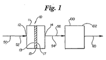
図1を参照して、本発明のフィルタ組立体10の一つの適用例は、空気から汚染物質を取り除き、低温の触媒反応で使用するような装置に使用される。
【0016】
図1に表現されるように、大気または周囲の空気50は入口12を通ってフィルタ組立体10に入る。このフィルタ組立体10に入る前の大気50は、様々な物理的汚染物質(例えば、微粒子)および化学汚染物質を持った汚い空気52である。フィルタエレメント15は、出口14を通してフィルタ組立体10から出されるきれいな空気54を供給するために、汚い空気52を濾過する。きれいな空気54が、設備100の吸気空気56となる。この実施例では、設備100は燃料電池102である。この設備100はこの吸気空気56を利用して作動し、排気60は設備100から出る。
【0017】
図1を参照して、本発明のフィルタ組立体10は、フィルタ組立体10の様々なフィルタエレメントに対して空気を送るための入口12を持っている。このフィルタ組立体10は、汚い空気側13と綺麗な空気側17を有した少なくとも1つのフィルタエレメントを有する。ほとんどの実施例において、フィルタエレメント15はハウジング11内で取り囲まれるか別の方法でケースに入れられる。また、フィルタ組立体10は、フィルタ組立体10で取り除かれた空気を燃料電池102か他の設備100に受け渡すための出口14を含む。
【0018】
大気50は、ハウジング11の入口12を介してフィルタ組立体10中に入り、フィルタエレメント15の汚い空気側13に進む。空気がフィルタエレメント15を通過し、綺麗な空気側17に通り抜けるときに、汚染物質が除かれて濾過された空気54が供給される。この濾過された空気は、フィルタのハウジング11の出口14を介して通過して、設備100で使用される。濾過された空気54を提供するために空気中から取り除かれる汚染物質の種類と量は、空気50中に存在している汚染物質と少なくとも1つのフィルタエレメント15に依存する。
【0019】
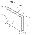
このフィルタエレメント15の構成としては、概ね2次平面となるパネルフィルタ構造にすることができる。このパネルフィルタエレメント15’の一例は図2に示される。確認を容易にするために、図1で述べた主要な構成であって同じ機能をする構成についは、図2においてプライム附合(’’’’’)を各番号に付与して示してある。これは図3に示した構成でも同じである。
【0020】
最初に、汚い空気52 がパネルフィルタ 15’の空気側13’ に入り、フィルタ媒体25を通過し、次に、浄化された空気54として空気側17’ から出る。このパネルフィルタ15’は、第1の側13’と第2の側17’の一方または双方において、フィルタ媒体25を保護するとともに、特に大きな微粒子または破片を取り除くための外側のライナー28を備えている。このフィルタ媒体25は、後述するように少なくとも一つの微粒子濾過エレメントと化学濾過エレメントを少なくとも備える。いくつかの実施例では、フィルタ媒体25は、微粒子状の汚染物質と化学的な汚染物質の双方を除去する。
【0021】
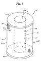
これに代えて、図3に示すようにフィルタエレメント15は、管状または円環状のフィルタエレメント15’’の構造にすることができる。一般的に、管状のフィルタエレメントは二つの端部キャップ41、42の間におけるフィルタ媒体25’の延設部分を含む。このフィルタエレメント15は内部容積部35を規定する外側面32と内側面34とを有している。第1の端部キャップ41は、内部容積部35への接近を許容するために主に「開口」しており、第2の端部キャップ42は管状のフィルタエレメント15’’の底部全体を横切るように延設された主に「閉じた」端部キャップである。外側ライナー28’をフィルタエレメント15’’の外周面32の上に配置することでフィルタ媒体25’を保護することができ、内側ライナーを内周面34の上に配置することができる。このフィルタ媒体25’は、後述するように少なくとも一つの微粒子濾過エレメントと化学濾過エレメントを少なくとも備えるか、フィルタ媒体25’は微粒子及び化学的汚染物質の除去ができる。
【0022】
この管状のフィルタエレメント15’’によれば、空気はフィルタ媒体25’に対して相対的に内側/外側(すなわち、「逆方向の流れ」)の方向に流れるか、外側/内側(すなわち、「正方向の流れ」)の方向に流れるように案内される。図3において、汚い空気52がフィルタ媒体の外周面32から入り、内周面34を通過してから内部容積部35を通過する様子が示されている。このような実施例では、外周面32が汚い空気側13’’となり内周面34が綺麗な空気側17’’である。「逆方向の流れ」では、内周面34が汚い空気側となり外周面が汚い空気側になるであろう。
【0023】
パネルフィルタエレメント15’と管状のフィルタエレメント15’’は、物理的(例えば、微粒子)汚染物質と、化学汚染物質のいずれか一方または双方を取り除くように設計される。特に、パネルフィルタ15’のフィルタ媒体25と管状のフィルタエレメント15’’のフィルタ媒体25’は、物理的(例えば、微粒子)汚染物質と、化学汚染物質のいずれか一方または双方を取り除く能力を有する材料から選択される。各種類の汚染物質の除去のために別々のフィルタエレメント部分を使用できるが、単一のフィルタエレメントで複数種類の汚染物質の除去をすることができる。好ましくは、必ずしも限定されるものではないが、別々の微粒子フィルタ部分が微粒子などの物理的な汚染物質を取り除くために使用され、化学フィルタ部分が化学汚染物質を取り除くのに使用される。この構成は、フィルタの目詰まりなどが発生しないようにするために、化学汚染物質が化学フィルタ部分に到達する前に、大きな微粒子を取り除くことで化学フィルタエレメントの効率を最大にすることが望ましい。
【0024】
フィルタエレメントの物理フィルタ部分
本発明のフィルタ組立体10において、特にパネルフィルタエレメント15’または管状のフィルタエレメント15’’のようなフィルタエレメント15は、入ってくる空気から微粒子のような物理的汚染物質を除去する部分が含まれる。複数の微粒子フィルタ部分を併設し、隣り合うフィルタ部分で次第に小さいサイズの微粒子を除去するように構成できる。またはこれに代えて、一つの微粒子フィルタ部分を使用できる。
【0025】
目の粗いフィルタ部分は、葉、種子、紙と他のゴミと破片、綿花、齧歯動物などの小動物のような大きい汚染物質を、装置の吸気管から除去するように配置されることが望ましい。このような粗いフィルタ部分は、格子、網目のようなものであり、金属、プラスチックまたは適当な材料から形成されるとともに、フィルタエレメント15を取り囲むハウジング11の入口12に組み入れられる。この粗いフィルタ部分は、一般的に少なくとも約1インチ(約2.5cm)の直径以上を有するサイズの物体を除去し、また別の実施例ではより代表的には少なくとも約0.5インチ(約1.25cm)の直径以上を有するサイズの物体、または少なくとも約0.25インチ(約0.635cm)の直径以上を有するサイズの物体を除去する。
【0026】
通常は、微粒子フィルタ部分は、繊維状マットや織物、紙などのフィルタ媒体を含み、約0.01mmのサイズの粒子を取り除く。この微粒子フィルタ部分で除去される微粒子は粉塵、 ゴミ、 花粉、 昆虫、 木製のチップ、 のこぎり粉塵、 金属削りくずのようなものがある。
【0027】
フィルタ媒体は微粒子を除く際に、その効率を改良するために種々の処理方法で処理され、例えば静電処理された媒体、または一層または多層のファインファイバーを有するセルロース媒体、または当業者間で知られているほかの媒体がある。
【0028】
HEPA(高い効率の粒子空気)フィルタなどのサブミクロンフィルタ部分をフィルタ組立体に含ませることができる。このサブミクロンフィルタは、燃焼やバクテリアやウイルスのようなものによって作り出されるエーロゾルなどの超微粒子を取り除くことを、通常は意図している。
【0029】
この微粒子フィルタ部分は、入って来る空気から雨とみぞれのような液体汚染物質を取り除くように設計することができる。空気中から液体を除去するために、空気の流れは高い表面エネルギーを有する材料を利用したフィルタ部分を通ることが望ましい。疎水性の表面を有する媒体は凝集によって液体汚染物質を取り除く。この疎水性表面を有するグラスファイバーをコーティングしたものは、液体汚染物質を取り除くための媒体の一事例である。液体汚染物質を取り除くための他の媒体の事例には発泡した金属ビーズを組み合わせた処理グラスファイバーがある。これらの媒体はフィルタ媒体の延設部分に、ひだ付きの紙延設部分として組み込むことができる。他の実施例では、燃料電池装置の内部で利用可能な空間如何では液体汚染物質を取り除くために慣性力を利用した分離装置を使用すると良い。拡張されたPTFE(ポリテトラフルオロエチレン)膜もさらに空気中から液体汚染物質を取り除くために使用できる。この拡張されたPTFEは、微細多孔性膜であり孔サイズが小さいので液体は通さず湿気(蒸気)のみの通過を許容する。
【0030】
微粒子の除去効率を有する様々の組み合わせのフィルタ部分を使用することができることが理解される。望ましい粒子除去システムは、大気中に存在する汚染物質の種類(例えば、葉、綿花、粗い綿、雪など)に存在するとともに、必要となる清浄度レベルに依存する。
【0031】
フィルタエレメントの化学フィルタ部分
本発明のフィルタ組立体10において、特にパネルフィルタエレメント15’または管状のフィルタエレメント15’’のようなフィルタエレメント15は、大気から吸着または吸収によって汚染物質を除去する部分が含まれる。ここで、「吸着」、「吸収」、「吸着剤」とした事項は、吸着または吸収するメカニズムも意味するように意図されている。
【0032】
化学フィルタ部分は、代表的には物理的吸着剤または化学的吸着剤を含み、これらには、例えば乾燥剤(例えば、水か水蒸気を吸着するかまたは吸収する材料)や揮発性の有機的な化合物又は酸性のガスの一方または双方を吸着する材料やこれらの複合材料が通常含まれる。このような適当な吸着性の材料には、例えば活性炭、活性炭ファイバー、飽和炭素、活性アルミナ、分子ふるい材料、イオン換樹脂、イオン交換ファイバー、シリカゲル、アルミナとシリカがある。これらの材料を結合または飽和することで過マンガン酸カリウム、炭酸カルシウム、炭酸カリウム、炭酸ナトリウム、硫化カルシウムやこれらの混合物にすることができる。また、いくつかの実施例では、吸着性の材料を第2の材料とともに組み合わせるか飽和することができる。いくつかの設計では、吸着性の材料として活性炭素のベッド状のものを飽和炭素の上流側に設けることが望ましい。
【0033】
この吸着性の材料としては、代表的には、顆粒状、ビーズ、繊維、細かい粉、ナノ構造体、ナノチューブ、エアロゲル(aerogels)のような粒状または顆粒状材料があり、またはセラミックビーズ、単一構造体、紙媒体、金属製基部上に塗装される材料として存在する場合がある。通常は、吸着性の材料(特に微粒子または粒状にされた材料)は材料のベッドとして供給される。
【0034】
これに代えて、吸着性の材料を、大型錠剤、顆粒、ビーズ、または折りたためるかハニカム構造であって、さらに形状付けできるように単一形状または一体形状にすることができる。少なくとも、ある事例では吸着性の材料はフィルタ組立体の正常な寿命の期間内においてその形状を実質的に保つ。この吸着性の材料は自由に流動する微粒子材料を、固体または液体のバインダーで結合し、その後、流動しない物体の形状に加工することができる。この吸着性の材料は、例えば成型、圧縮成形または押し出し成型によって形成することができる。
【0035】
バインダーは、粉または粒状の形態で乾燥しているものや、液体中に溶けた状態のものや液体中に分散しているものが使用される。湿度で硬化するウレタンやて代表的に「ホットメルト(熱溶融)」として参照される材料がバインダーとして、吸着性の材料に直に噴霧するようにして使用することができる。他の実施例では成型過程の間に取り除くことができる溶剤か分散剤を含む一時的な液体バインダーを使用できる。このような適当なバインダーは、例えばラテックス、マイクロ結晶化セルロース、ポリビニル・アルコール、澱粉、カルボキシル・メチル・セルロース、ポリビニルピロロリドン(polyvinylpyrrolidone)、ダイカルシウム燐酸塩、およびナトリウム・シリケートが含まれる。
【0036】
望ましくは、形成材料の構成は、少なくとも70重量%、代表的には98重量%の吸着性の材料を含む。他の事例では、形成材料の構成は、85から95重量%であり、好ましくは約90重量%の吸着性の材料を含む。形成材料は吸着性の材料が約2重量%以下のバインダーを含み、またバインダーの30重量%以上を含む。この成型についての型開き、添加剤、及び他の成型技術に関する記載は、米国特許番号5,876,487号に開示されている。
【0037】
化学フィルタ部分で使用される他の実施例となる適当な吸着性の材料としては、媒介体を含む吸着性の材料がある。例えば、吸着性の材料とバインダーとを保持させるためにメッシュ(網)かスクリム(幕)を使用することができる。このメッシュかスクリムとしてポリエステルと他の適当な材料を使用することができる。通常どんな媒介体も吸着性の材料の約50重量%以下に設定され、主に吸着性の材料の約20から40重量%に設定される。形状付けされた媒介体を有する吸着性の材料体のバインダーの量は、総吸着性の重さの約10から50%の範囲となり、吸着性の材料の量は、通常は総吸着性の重さの約20から60%の範囲となる。
【0038】
化学フィルタ部分は、空気中の汚染物質の除去のための強い基本的な材料を有するか、空気中の酸性物の基本的な汚染物質の除去のための基本的な材料のいずれかまたは双方を持つことができる。好ましくは、これらの強い基本的な材料と酸性物の除去の基本的な材料とは互いに離されることで互いに干渉しないようにすると良い。大気空気中に存在する酸性の化合物としては例えば、硫化酸化物、窒素酸化物、硫化水素、水素塩化物、揮発性の有機的な酸および不揮発性の有機的な酸がある。また、大気空気中の基礎成分としては、アンモニア、 アミン、アミド、水酸化ナトリウム、水酸化リチウム、水酸化カリウム、揮発性の有機物と不揮発性の有機物とがある。一般に、化学フィルタ部分の基本的な材料と酸性の材料により、空気中の汚染物質を表面で捕捉することで除去するが、通常は、 酸性の表面材料と汚染物質とが化学反応する結果、少なくとも表面の汚染物質が吸着される。
【0039】
いくつかの実施例では、媒介体のそれ自体が強い基本的な材料または酸性の基本的な材料となる。このような材料としては例えば高分子微粒子、活性炭媒体、ゼオライト、 粘土、シリカゲルおよび金属酸化物などの材料が含まれる。他の実施例では、強酸性の基本的な材料とより強い材料の媒介体として、表面上に粒状のビーズ、繊維体、細粉体、ナノチューブ、エアロゲルを塗装するようにしても良い。さらに、これに代えて強い基本的な表面または酸性の基本的な表面とを媒介体の一部に形成するために、媒介体を酸性液または基本材料中に漬けるようにしても良い。
【0040】
アンモニアのような基本的な汚染物質を取り除くための好ましい材料としては、クエン酸をしみ込ませた活性炭顆粒のベッドがある。
【0041】
基本的な酸性汚染物質を取り除くための好ましい材料としては、ラファエット・カンパニのアイオネックスリサーチ分社において、「ケミソーブ1202」としてシー*ケミ社から販売されており入手可能な飽和活性炭素果粒がある。
【0042】
フィルタエレメントにおいて基本的な材料と酸性の基本的な材料の双方が化学フィルタ部分に存在することになるが、しかしながらこれらの材料は互い反応せず中和するように離すように設けると良い。
【0043】
この化学フィルタ部分は、特定の汚染物質の除去のために専用に作られた他の材料を含むことができる。一例として、一酸化炭素を空気中から除去するために強い酸性材料を含むことができる。この強酸性材料は、例えば、触媒材料として名称「ホップカライト(Hopcalite)」(多孔性のマンガン酸化物と銅の酸化物の混合物)でピッツバーグのMSA社から販売されている材料、貴金属、これらの遷移金属とこれの組み合わせ材料、「ホップカライト」と同様の材料の貴金属、遷移金属、無機有機的な酸化物、塩と金属、過酸化水素、パーマンガンテス(permangantes)とクロム酸塩とがある。
【0044】
強酸化材料は窒素酸化物(NOx)を空気中から除去する材料に含めることができる。
【0045】
この化学フィルタ部分は汚い空気流中から汚染物質を捕捉し、永久に保持するか、または化学フィルタ部分は後に化学汚染物質を放出するかもしれない。例えば、化学フィルタ部分は汚い空気流から化学汚染物質を除去することで、フィルターにかけられた後の綺麗な空気は、燃料電池などの設備に導入されるときに許容できる閾値以下の汚染物質の濃度となる。汚い空気中の汚染物質のレベルが閾値以下であるときには、フィルタエレメントは汚染物質の除去は必要でなくなり、むしろある実施例では、化学フィルタ部分は集合した汚染物質を閾値になるまで放出する。この放出は、汚い空気の流れ中の汚染物質濃度と化学フィルタ部分に集合した汚染物質濃度の差によって一般的に発生する。このようにして、化学フィルタ部分は部分的に再生されることで、化学フィルタ部分の使用寿命が延長されるであろう。燃料電池に対する汚染物質濃度の許容閾値レベルが分かっているときに、このような設計が望ましい。
【0046】
微粒子フィルタ部分と化学フィルタ部分とを組み合わせることで一つのフィルタエレメントを作り、物理的及び化学的な汚染物質の双方を除去することができる。一つの実施例では、微粒子フィルタ部分の濾過媒体は化学的に吸収可能な表面処理がされたかまたは酸性あるいは基本的な汚染物質を相互作用する繊維から作ることができ、化学的濾過部分を形成できる。他の事例では、活性炭素顆粒のベッドを設けることで顆粒体の大きさが充分に小さい場合において空気中から物理的な汚染物質を除去できる。
【0047】
一つの実施例では、化学フィルタ部分をバイパスするようなバイパスシステムを提供することが望ましいであろう。この構成によれば、吸気される空気が化学汚染物質でかなり汚染されていない場合に望ましい。このバイパスシステムは吸気される空気流中の汚染物質レベルに応じて、活性化と再度活性化されることになる。
【0048】
好適なフィルタ組立体
好適なフィルタ組立体の第1の事例は、微粒子と化学物質の両方の濾過能力を有するフィルタ組立体である。この特定の実施例では、フィルタ組立体には物理フィルタ部分となる一つの層の微粒子媒体と、化学フィルタ部分となる3層の吸収媒体とを有している。好ましくは、この物理フィルタ部分は化学フィルタ部分の上流側に設けられることで、浄化されるべき空気流は最初に微粒子フィルタ部分を通過し、次に化学フィルタ部分を通過すると良い。吸収媒体の3層の各層は、他のベッドから穴明きアルミ製の分離板によって互いに離隔されるように保持された顆粒状の材料をベッド状にしたものである。
【0049】
一般的に、好適なフィルタ組立体の構造は、二つの封入された顆粒状の炭素製ベッドと中心の静電媒体の回りに位置される微粒子フィルタとしての折り目を付けたガラス媒体を有する。
【0050】
この微粒子フィルタ部分は、好ましくは濾過技術において良く知られている折り目を付けたガラス繊維媒体の構造体である。ホットメルト接着剤のようなベッド用の材料は、折り目の分離のために使用することができる。
【0051】
好ましい実施例では、化学フィルタ部分の第1の層は、クエン酸で飽和された約35重量%の活性炭素から構成される。好ましくは、米国カリフォルニア州、リッチモンドのカルゴン・カーボン社から「RVCA12」、「RVCA35」の商品番号で販売されている8X16メッシュのサイズの材料が使用可能である。この第1の層は、いくつかの炭化水素と他の有機材料と同様に、空気の流れからアンモニアとアミンを取り除く。化学フィルタ部分の第2の層は第2の飽和活性炭を含む。望ましくは、8X16メッシュの材料は商品名「ケミソーブ1202」として販売されており入手可能なものがある。この第2の層は、酸性のガス、炭化水素、他の有機的な材料を取り除くために使用される。第3の層は、触媒の層である。この化学フィルタ部分の層は、12X20メッシュのサイズの材料が使用されるが、これはカルース・ケミカル社から商品名「カルライト300」で販売されており入手可能なものである。この層は、一酸化炭素を二酸化炭素に酸化する。
【0052】
第2の好ましいフィルタ組立体の実施例は、第1の実施例に似たものであって、第1の層の飽和活性炭素の「RVCA12」、「RVCA35」に代えて非−炭素系の吸収媒体にしたものである。
【0053】
第3の好ましいフィルタ組立体の実施例は、第1の実施例に似たものであって、第1の層の飽和活性炭素の「RVCA12」、「RVCA35」に代えて非−炭素系の触媒体にしたものである。
【0054】
第4の好ましいフィルタ組立体の実施例は、第1の実施例に似たものであって、第2の層の飽和活性炭素の「ケミソーブ1202」に代えて非−炭素系の吸収媒体にしたものである。
【0055】
第5の好ましいフィルタ組立体の実施例は、第1の実施例に似たものであって、第2の層の飽和活性炭素の「ケミソーブ1202」に代えて非−炭素系の触媒体にしたものである。
【0056】
さらに、他の実施例として一つまたは二つの封入された炭素材料のベッドを、適度な芯またはライナーの回りに巻き付けた炭素材料の繊維で置き換えるものもある。
【0057】
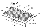
図4と図5を参照して、本発明の原理に基づく二つのフィルタ組立体の物理的な構成を示す実施例が示されている。図4において、フィルタ組立体10は、第1の側112と第2の側114を有したハウジング105を設けたパネルフィルタ110の特徴を備えている。このパネルフィルタ110は、第1の側112に物理フィルタ部分120を含んでいる。この物理フィルタ部分120は、葉や破片などのような大きな物体を取り除くためのルーバー状の格子116として構成されている。格子116はハウジング105と一体的または取り外し可能に設けることができる。このハウジング105からは、格子116から離れるようにフランジ107が延設される。燃料電池のようなあらゆる種類の吸気口に対して改善されたシールを提供するために、このフランジ107においてガスケットを設けることができる。
【0058】
一つの実施例では、パネルフィルタ110は格子116からフランジ107を設けた第2の側114までの深さが約4.15インチ(およそ10.5cm)であり、フランジの厚さは約0.25インチ(およそ0.635cm)であり、第2の側114から約3.21インチ(およそ8.15cm)の場所に位置している。このフランジ107を含まないハウジング102の大きさは、その幅が約15インチ(およそ38cm)であり高さが7インチ(およそ17.8cm)である。フランジ107を含めると、幅は約17.25インチ(およそ43.8cm)であり高さが約9.25インチ(およそ23.5cm)である。ここで、当業者はこのような寸法は、フィルタが使用される適用例に基づき、種々設定されることが理解されよう。
【0059】
パネルフィルタ110で濾過されるべき空気は、大きなゴミを除去する格子116を介して内部に入る。この格子116の背後には、他の物理的なフィルタ部分と化学的なフィルタ部分とこれらの双方が設けられている。好ましくは、上述したような形式の少なくとも一つの化学フィルタ部分が格子116の背後においてハウジング105の内部に配設されていると良い。格子116と他のあらゆる種類の物理フィルタ部分または化学フィルタ部分とを通過して濾過された空気は、第2の側114からパネルフィルタ110の外部に出る。
【0060】
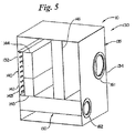
図5を参照して、フィルタ組立体10は6つの側面を備える箱形状のフィルタ組立体130である。図5において、ハウジング135 はフィルタ組立体130の説明を容易にするために一つの側面を省略して示している。このフィルタ組立体130は、第1の側132と第2の側134を有している。
【0061】
このハウジング135 の内部には、物理フィルタ部分140 と化学フィルタ部分150とが設けられている。種々の邪魔板と流路とがハウジング135の内部に設けられており、所望の空気流を得るようにしている。物理フィルタ部分140には、汚い大気空気を取り入れるために開口部143を形成した多孔スクリーン142が設けられている。開口部143を通過する空気中からは、葉や破片などの大きな物体が除去される。この部分から、空気は液体除去部144を通過することで、雨などの水分を水滴とし、ドレイン回収部145で回収され、ハウジング135の外部への排水を可能にしている。高い効率の微粒子フィルタ146が、開口部143を通り抜けた微粒子を取り除くために含まれている。フィルタ組立体130は、化学汚染物質を吸着するための顆粒状の炭素のベッドまたは吸着剤を組み合わせた化学フィルタ部分150を含む。図5に図示の実施例では、導入された空気は高い効率の微粒子フィルタ146を迂回し、液体除去部144を通過した後に、化学フィルタ部分150に進むことが可能となる。このような流路は、例えは高効率フィルタ146が目詰まりして流れが防止された場合において、フィルタ組立体130を通過する空気の流れを維持するために望ましいことになるであろう。
【0062】
ハウジング135の第2の側134には、出口161と第2の出口162がある。第1の出口161を介して、フィルタ組立体130で濾過された綺麗な空気が、電気装置のような包囲体の中に送られる。第2の出口162はフィルタ組立体130で濾過された綺麗な空気を燃料電池のような装置に送る。この第2の出口162を介して出る空気は、第1の出口161を出るのにつれて、同じ濾過工程を経て外部に出るか、または異なる濾過動作が種々の流れにおいて行うことができる。一つの実施例では、第2の出口162を介して出る空気は、物理フィルタ部分140の全ての構成部分を通過し、さらに化学フィルタ部分150を通過する一方で、第1の出口161を介して出る空気は、物理フィルタ部分140の全ての構成部分のみを通過することとなる。
【0063】
一つの実施例では、フィルタ組立体130は、約12インチと17インチと13インチ(およそ30.5cmと43.2cmと33cm)であり、多孔を有するスクーン142を有する第1の側132は、約12インチ(およそ30.5cm)幅であり、約17インチ(およそ43.2cm)の高さである。湿った空気中の液化で液体を除去する液体除去部144は、約12インチと5.25インチと2インチ(およそ30.5cmと13.3cmと5cm)である。微粒子フィルタ146は、約10インチと12インチと4インチ(およそ25.4cmと30.5cmと10.2cm)である。化学フィルタ部分150は、約12インチと11インチと3インチ厚さ(およそ30.5cmと27.9cmと7.6cm)である。このような実施例によれば、毎分約約55立方フィートcfm(毎分およそ、1.56メートル)の汚い空気を処理することができ、毎分で35cfm(毎分およそ、1立方メートル)で第1の出口161を介して出すことができ、毎分で20cfm(毎分およそ、0.6立方メートル)で第2の出口162を介して出すことができる。
【0064】
燃料電池
図1において、本発明のフィルタ組立体10が作動する設備100として燃料電池 102として表現されている。この燃料電池は電解質(液)を挟むように配設された二つの電極(陽極と陰極)を備えた装置である。水素を含む燃料は陽極に注がれ、そのときに水素電子が自由に分離され、陽電荷のイオンとして残る。電荷は、電解質中にそのイオンが拡散するようにして内部電子回路を伝わる。陰極では、電子は水素イオンと酸素と化合して、水と二酸化炭素及び副産物を発生する。この反応を促進するために触媒(体)が多く使用される。この触媒としては、ニッケル、プラチナ、パラジウム、コバルト、セシウム、ネオダイミウム(neodymium)などの希土類金属がある。燃料電池内での反応物質は、水素と酸化性物質である。
【0065】
通常は、燃料電池102に使用されるフィルタ組立体は、約70〜90℃の範囲の低い運転温度である「低温燃料電池」用として知られている。また、高温燃料電池も知られているが、これらはそれらのより高い運転温度のために化学汚染に敏感でないとされている。高温燃料電池は、しかしながら微粒子汚染物質と、ある種の形態の化学汚染物質に対して敏感であることから、上記の濾過システムによる何らかの利益を得ることもあろう。一つのタイプの低温燃料電池は、一般にプロトン変換膜の使用にちなんで「PEM」と命名される。PEM燃料電池を、本発明のフィルタ組立体と関連して使用することによって利益を得ることができるであろう。本発明のフィルタ組立体と組み合わせて使用することができる燃料電池のほかの機種に関する例は、例えば米国特許第6,110,611と、6,117、579と、6、103,415と、6、083、637号が含まれる。燃料電池に拘わる当業者は、フィルタ組立体は一般的に全ての燃料電池の動作に有益となることを理解するであろう。
【0066】
様々な燃料電池によって許容できる汚染物質の閾値レベルは燃料電池の設計如何に依存する。例えば、炭化水素(メタンとそれより重い物質)と、アンモニア、硫化酸化物、一酸化炭素、シリコンおよび同様のものなどは、触媒の空間を占有して反応を不活発にする。したがって、これらの汚染物質は、それらが燃料電池の反応領域に入る前に取り除く必要がある。
【0067】
使用される触媒、運転条件および触媒の反応条件によって、正確な許容可能な汚染レベルおよびタイプ汚染物質は異なるであろう。
【0068】
本発明のフィルタ組立体によれば、大気空気は燃料電池の運転で使用される前に、汚染物質が取り除かれる。
【0069】
ここで、上記の構造の開示と、この開示とともに以上の記述で詳しく説明された範囲に留まらず、サイズおよびアレンジメント変更は任意に可能であって、請求の範囲に規定された種々の構成についても本発明に吹く舞えることは言うまでもない。
【図面の簡単な説明】
【図1】
図1は、本発明のフィルタ組立体を含む電力発生システムの概要を示した模式図である。
【図2】
図2は、図1のフィルタ組立体を使用するためのフィルタエレメントの第1の実施例の概要を示した外観斜視図である。
【図3】
図3は、図1のフィルタ組立体を使用するためのフィルタエレメントの第2の実施例の概要を示した外観斜視図である。
【図4】
図4は、フィルタ組立体の好適な具体例の外観斜視図である。
【図5】
図5は、フィルタ組立体の別の好適な具体例の外観斜視図である。[0001]
This application was filed on September 12, 2000, with the names of the applicants of the Donaldson Company, Inc. of the United States, filed as a PCT international patent application on September 12, 2001, specifying all countries except the United States. No. 09 / 660,127.
[0002]
(Field of the Invention)
The present application relates to an air filter system for a low temperature catalytic process. In particular, the present disclosure relates to an air filter used in a fuel cell device.
[0003]
(Background of disclosure)
All atmospheric air in today's world has some contaminants, which are unavoidable. These contaminants include large ones such as dead leaves, pieces of torn paper, cotton blossoms, insects, and the like, and small enough to be dispersed in the air like fine particles. Such particulates include dust, pollen, smog and smoke dust.
[0004]
Chemical pollutants are also widely present in atmospheric air. Many of these are the result of man-made contamination, but other chemicals also occur naturally. Typical pollutants include hydrocarbons such as methane, butane, propane, and volatile organic compounds such as oxides and sulfates of ammonia and nitrogen, and carbon monoxide and hydrogen sulfide.
[0005]
Most machines today, such as automobiles, will be designed to filter or contaminate contaminants that may cause problems in their operation. For example, large size contaminants, such as leaves and paper, are removed from the air intake stream by motor vehicle grilles and various vents. This arrangement also removes small animals such as birds, squirrels and mice that may invade the engine. Finer contaminants such as dust are removed by an air filter disposed in the engine room. And for a typical automobile and a group of internal combustion machines (eg, lawnmowers, snow blowers, snowmobiles, etc.), even if the effects of chemical contaminants on the function of the equipment are present, the engine combustion At the stage of generating power in the process, the effect is very small because it can withstand the chemical pollutants present in the intake air.
[0006]
There are still some machines and systems that have not been optimized to operate optimally in today's polluted atmosphere. The reason for this is that the importance of purified intake air required for efficient and / or optimal operation conditions is not recognized, or contaminants in the air reduce the performance of the machine This is because the point has not yet been optimally recognized or defined.
[0007]
BACKGROUND OF THE INVENTION Fuel cells, which are rapidly becoming the source of electricity for both residential and commercial purposes, are one type of system that is not yet fully understood. This fuel cell is a device composed of two electrodes (anode and cathode) sandwiching an electrolyte. Depending on the size, shape, and design of the cell, the fuel cell can provide enough energy to run mobile phones, computers, cars, residential homes or even power plants. Fuel cells typically operate with fuel resources supplied to the anode side of the cell and oxidant supplied to the cathode side. A commonly used fuel is, for example, hydrogen.
[0008]
Many fuel cells are not designed to operate efficiently with large amounts of contaminants in the intake air required for the function of the fuel cell. Further, fuel cells are generally not designed to handle or filter pollutants in the intake air. The reason for this is that the operating parameters are not defined because the fuel cell and its operation are new technologies. In general, the overall capabilities and limitations of a fuel cell are not fully understood.
[0009]
Therefore, what is desired is a fuel cell that can function in an environment with a wide range of contaminants.
[0010]
(Summary of disclosure)
SUMMARY OF THE INVENTION The present invention provides an air filter assembly for filtering intake air used in a low temperature catalytic reaction such as a fuel cell. The assembly provides for specific and / or chemical filtration of the inspired air flow to provide purified oxidant to the cathode side of a catalytic reactant such as a fuel cell.
[0011]
The filter assembly captures and traps either or both particulates and / or chemical contaminants that inhibit chemical catalysis. According to one embodiment of the filter assembly, chemical contaminants are captured and temporarily retained and released when the level of contaminants in the introduced dirty air falls below acceptable levels.
[0012]
This filter assembly is useful in low temperature catalysis processes. This filter assembly can be used to filter air used in fuel cells, such as a proton conversion membrane (PEM).
[0013]
In one embodiment, a system for generating power is provided. The system is an air filter assembly including a housing and a filter element in the housing. The housing has an inlet and an outlet, the inlet supplying dirty air to the filter assembly, and the outlet supplying clean air from the filter assembly. The filter element includes a physical or particulate filtration portion that is assembled and disposed to remove particulate contaminants from dirty air and a chemical filter portion for removing chemical contaminants from dirty air. The system further includes a fuel cell having an air inlet. The air filter assembly is assembled and arranged to supply clean air from the outlet of the filter assembly to the intake of the fuel cell.
[0014]
In another embodiment, a filter assembly for use with a fuel cell is provided. The filter assembly has a housing and a filter element in the housing. The housing has an inlet and an outlet, the inlet providing dirty air to the filter assembly, and the outlet providing clean air from the filter assembly. The filter element includes a physical or particulate filtration portion that is assembled and disposed to remove particulate contaminants from dirty air and a chemical filter portion for removing chemical contaminants from dirty air. In particular, the chemical filter section is assembled and disposed to remove ammonia and amines from dirty air. To this end, a first part comprising a saturated activated carbon adsorption medium and a second part assembled and arranged for removing acidic gases and organic materials from dirty air, said second part Consists of a saturated activated carbon adsorption medium and comprises a third part which oxidizes pollutants in dirty air, this third part comprising the material of the catalyst. Also, a fourth part and necessary additional parts can be included.
[0015]
(Description of the preferred embodiment)
Referring to FIG. 1, one application of the filter assembly 10 of the present invention is used in an apparatus for removing contaminants from air and for use in low temperature catalytic reactions.
[0016]
As depicted in FIG. 1, atmospheric or ambient air 50 enters filter assembly 10 through inlet 12. The atmosphere 50 before entering the filter assembly 10 is
[0017]
Referring to FIG. 1, the filter assembly 10 of the present invention has an inlet 12 for sending air to various filter elements of the filter assembly 10. The filter assembly 10 has at least one filter element with a
[0018]
Atmosphere 50 enters filter assembly 10 via inlet 12 of housing 11 and travels to
[0019]
The configuration of the filter element 15 may be a panel filter structure having a substantially secondary plane. An example of the panel filter element 15 'is shown in FIG. In order to facilitate the confirmation, the main configuration described in FIG. 1 and having the same function is indicated by a prime attachment (''''') given to each number in FIG. . This is the same in the configuration shown in FIG.
[0020]
First,
[0021]
Alternatively, as shown in FIG. 3, the filter element 15 can be in the form of a tubular or annular filter element 15 ″. Generally, the tubular filter element includes an extension of the filter media 25 'between the two
[0022]
With this tubular filter element 15 ″, air flows inward / outward (ie, “reverse flow”) relative to the
[0023]
The panel filter element 15 'and the tubular filter element 15''are designed to remove physical (eg, particulate) contaminants and / or chemical contaminants. In particular, the
[0024]
Physical filter part of filter element
In the filter assembly 10 of the present invention, in particular, the filter element 15 such as a panel filter element 15 'or a tubular filter element 15''includes a portion that removes physical contaminants such as particulates from incoming air. It is. A plurality of fine particle filter portions can be provided in parallel, and the filter portions adjacent to each other can remove fine particles of gradually smaller size. Alternatively, one particulate filter portion can be used.
[0025]
The open filter portion is desirably arranged to remove large contaminants such as leaves, seeds, paper and other debris and debris, cotton, small animals such as rodents from the intake pipe of the device. . Such a coarse filter part is like a grid, a mesh, is made of metal, plastic or a suitable material and is incorporated in the inlet 12 of the housing 11 surrounding the filter element 15. The coarse filter portion removes objects sized generally having a diameter of at least about 1 inch (about 2.5 cm) or more, and in another embodiment more typically at least about 0.5 inch (about 2.5 cm). Remove objects having a diameter of at least 1.25 cm, or at least having a diameter of at least about 0.25 inches.
[0026]
Typically, the particulate filter portion includes filter media such as fibrous mats, fabrics, paper, etc., to remove particles of approximately 0.01 mm in size. The particulates removed by this particulate filter are dust, dirt, pollen, insects, wood chips, saw dust, and metal shavings.
[0027]
The filter media may be treated in a variety of treatments to improve its efficiency in removing particulates, such as electrostatically treated media, or cellulosic media having one or more layers of fine fiber, or those known to those skilled in the art. There are other media that are being used.
[0028]
A submicron filter portion, such as a HEPA (high efficiency particulate air) filter, can be included in the filter assembly. This submicron filter is usually intended to remove ultra-fine particles such as aerosols created by combustion and by things like bacteria and viruses.
[0029]
This particulate filter portion can be designed to remove liquid contaminants such as rain and sleet from incoming air. In order to remove liquid from the air, it is desirable that the air flow pass through a filter portion utilizing a material having a high surface energy. Media having a hydrophobic surface remove liquid contaminants by agglomeration. Glass fiber coatings with this hydrophobic surface are an example of a medium for removing liquid contaminants. Another example of a medium for removing liquid contaminants is treated glass fiber combined with expanded metal beads. These media can be incorporated into the extensions of the filter media as pleated paper extensions. In another embodiment, an inertial separation device may be used to remove liquid contaminants depending on the space available inside the fuel cell device. An expanded PTFE (polytetrafluoroethylene) membrane can also be used to remove liquid contaminants from the air. Since this expanded PTFE is a microporous membrane and has a small pore size, it does not allow liquid to pass through and allows only moisture (vapor) to pass.
[0030]
It is understood that various combinations of filter portions having particulate removal efficiency can be used. Desirable particle removal systems are present for the types of contaminants present in the atmosphere (eg, leaves, cotton, coarse cotton, snow, etc.) and depend on the required level of cleanliness.
[0031]
Chemical filter part of filter element
In the filter assembly 10 of the present invention, the filter element 15, particularly the panel filter element 15 'or the tubular filter element 15'', includes a portion that removes contaminants from the atmosphere by adsorption or absorption. Here, the terms “adsorption”, “absorption”, and “adsorbent” are intended to mean the mechanism of adsorption or absorption.
[0032]
The chemical filter portion typically includes a physical or chemical adsorbent, such as a desiccant (eg, a material that adsorbs or absorbs water or water vapor) or a volatile organic Materials that adsorb one or both of compounds or acidic gases and composites thereof are usually included. Such suitable adsorptive materials include, for example, activated carbon, activated carbon fibers, saturated carbon, activated alumina, molecular sieve materials, ion exchange resins, ion exchange fibers, silica gel, alumina and silica. By combining or saturating these materials, potassium permanganate, calcium carbonate, potassium carbonate, sodium carbonate, calcium sulfide, or a mixture thereof can be obtained. Also, in some embodiments, the adsorptive material can be combined or saturated with the second material. In some designs, it may be desirable to provide a bed of activated carbon as the adsorptive material upstream of the saturated carbon.
[0033]
The adsorptive material typically includes granular or granular materials such as granules, beads, fibers, fine powders, nanostructures, nanotubes, aerogels, or ceramic beads, single particles. It may be present as a material to be painted on structures, paper media, metal bases. Usually, the adsorptive material (particularly particulate or granulated material) is supplied as a bed of material.
[0034]
Alternatively, the adsorptive material may be large tablets, granules, beads, or a collapsible or honeycomb structure that can be unitary or integral to allow for further shaping. At least in some cases, the adsorptive material substantially retains its shape during the normal life of the filter assembly. This adsorptive material allows free flowing particulate material to be combined with a solid or liquid binder and then processed into the shape of a non-flowing object. The adsorptive material can be formed, for example, by molding, compression molding, or extrusion molding.
[0035]
As the binder, those that are dried in a powder or granular form, those that are dissolved in a liquid, or those that are dispersed in a liquid are used. Urethane that cures with humidity or a material typically referred to as “hot melt” can be used as a binder by spraying directly onto the adsorptive material. In another embodiment, a temporary liquid binder containing a solvent or dispersant that can be removed during the molding process can be used. Such suitable binders include, for example, latex, microcrystalline cellulose, polyvinyl alcohol, starch, carboxymethyl cellulose, polyvinylpyrrolidone, dicalcium phosphate, and sodium silicate.
[0036]
Desirably, the composition of the forming material comprises at least 70% by weight, typically 98% by weight of the adsorbent material. In other cases, the composition of the forming material is from 85 to 95% by weight, and preferably comprises about 90% by weight of the adsorbent material. The forming material comprises up to about 2% by weight of the binder with the adsorbent material and more than 30% by weight of the binder. A description of mold opening, additives, and other molding techniques for this molding is disclosed in U.S. Patent No. 5,876,487.
[0037]
Other suitable adsorbent materials for use in the chemical filter portion include adsorbent materials that include a mediator. For example, a mesh or screen can be used to hold the adsorbent material and the binder. Polyester and other suitable materials can be used as the mesh or scrim. Typically, any mediator will be set at about 50% or less by weight of the adsorptive material, mainly at about 20 to 40% by weight of the adsorptive material. The amount of binder in the adsorbent material body with the shaped mediator ranges from about 10 to 50% of the total adsorbent weight, and the amount of adsorbent material is usually In the range of about 20 to 60%.
[0038]
Chemical filter parts have either strong basic materials for the removal of airborne contaminants or either or both of the basic materials for the removal of airborne basic contaminants. Can have. Preferably, these strong basic materials and the basic material for removing acidic substances are separated from each other so as not to interfere with each other. Examples of acidic compounds present in atmospheric air include sulfide oxides, nitrogen oxides, hydrogen sulfide, hydrogen chloride, volatile organic acids, and nonvolatile organic acids. The basic components in atmospheric air include ammonia, amines, amides, sodium hydroxide, lithium hydroxide, potassium hydroxide, volatile organic substances and non-volatile organic substances. Generally, the basic material of the chemical filter part and the acidic material remove the contaminants in the air by trapping them on the surface, but usually, at least as a result of the chemical reaction between the acidic surface material and the contaminants. Surface contaminants are adsorbed.
[0039]
In some embodiments, the vehicle itself is a strong or acidic basic material. Such materials include, for example, materials such as polymeric microparticles, activated carbon media, zeolites, clays, silica gels, and metal oxides. In another embodiment, granular beads, fibrous bodies, fine powders, nanotubes, and aerogels may be painted on the surface as a medium between the strongly acidic basic material and the stronger material. Further, alternatively, the mediator may be immersed in an acid solution or a basic material to form a strong basic surface or an acidic basic surface on a part of the vehicle.
[0040]
A preferred material for removing basic contaminants such as ammonia is a bed of activated carbon granules impregnated with citric acid.
[0041]
A preferred material for removing basic acidic contaminants is saturated activated carbon granules available from Sea * Chemie under the trade name "Chemisorb 1202" at Ionex Research, Inc. of Rafayet Campani.
[0042]
In the filter element, both the basic material and the acidic basic material will be present in the chemical filter portion, however, it is preferred that these materials be spaced apart so that they do not react with each other and neutralize.
[0043]
The chemical filter portion can include other materials specifically made for the removal of certain contaminants. As an example, a strong acidic material can be included to remove carbon monoxide from the air. This strongly acidic material is, for example, a material sold by MSA in Pittsburgh under the name "Hopcalite" (a mixture of porous manganese oxide and copper oxide) as a catalyst material, a noble metal, Transition metals and their combination materials, noble metals, transition metals, inorganic and organic oxides, salts and metals, hydrogen peroxide, permanganates and chromates similar to "hopcalite" There is.
[0044]
Strongly oxidizing materials can be included in materials that remove nitrogen oxides (NOx) from the air.
[0045]
The chemical filter portion may trap the contaminants from the dirty air stream and retain them permanently, or the chemical filter portion may later release the chemical contaminants. For example, the chemical filter section removes chemical contaminants from dirty air streams, so that the clean air after being filtered can have a concentration of contaminants below an acceptable threshold when introduced into equipment such as fuel cells. It becomes. When the level of contaminants in the dirty air is below the threshold, the filter element need not remove the contaminants, but rather, in one embodiment, the chemical filter portion emits the collected contaminants until the threshold is reached. This emission is generally caused by the difference between the concentration of pollutants in the dirty air stream and the concentration of pollutants collected in the chemical filter section. In this way, the chemical filter portion will be partially regenerated, thereby extending the useful life of the chemical filter portion. Such a design is desirable when an acceptable threshold level of pollutant concentration for the fuel cell is known.
[0046]
One filter element can be made by combining the particulate filter portion and the chemical filter portion to remove both physical and chemical contaminants. In one embodiment, the filtration media of the particulate filter portion may be made of chemically absorbable surface treated or acidic or basic contaminant interacting fibers to form a chemical filtration portion. . In other cases, providing a bed of activated carbon granules can remove physical contaminants from the air when the granules are small enough.
[0047]
In one embodiment, it would be desirable to provide a bypass system that bypasses the chemical filter portion. This configuration is desirable when the air being drawn in is not significantly contaminated with chemical contaminants. The bypass system will be activated and reactivated depending on the level of contaminants in the intake air stream.
[0048]
Preferred filter assembly
A first example of a suitable filter assembly is a filter assembly having both particulate and chemical filtering capabilities. In this particular embodiment, the filter assembly has one layer of particulate media that will be a physical filter portion and three layers of absorbent media that will be a chemical filter portion. Preferably, the physical filter part is provided upstream of the chemical filter part, so that the air flow to be purified passes first through the particulate filter part and then through the chemical filter part. Each of the three layers of absorbent medium is a bed of granular material held apart from the other bed by a perforated aluminum separator.
[0049]
Generally, a preferred filter assembly construction has two encapsulated granular carbon beds and a fold glass medium as a particulate filter located around a central electrostatic medium.
[0050]
The particulate filter portion is preferably a crimped glass fiber media structure well known in the filtration arts. Bed materials such as hot melt adhesives can be used for crease separation.
[0051]
In a preferred embodiment, the first layer of the chemical filter portion is comprised of about 35% by weight activated carbon saturated with citric acid. Preferably, an 8 × 16 mesh size material sold by Calgon Carbon of Richmond, Calif., USA under the product designations “RVCA12” and “RVCA35” can be used. This first layer removes ammonia and amines from the air stream, as well as some hydrocarbons and other organic materials. The second layer of the chemical filter portion includes a second saturated activated carbon. Desirably, an 8 × 16 mesh material is available under the trade name “Cemisorb 1202”. This second layer is used to remove acidic gases, hydrocarbons and other organic materials. The third layer is a layer of the catalyst. The layer of the chemical filter portion is made of a material having a size of 12 × 20 mesh, which is available from Callus Chemical Company under the trade name “Callite 300”. This layer oxidizes carbon monoxide to carbon dioxide.
[0052]
A second preferred embodiment of the filter assembly is similar to the first embodiment, wherein the non-carbon based absorption of the saturated activated carbon "RVCA12" and "RVCA35" of the first layer is replaced. It is a medium.
[0053]
A third preferred filter assembly embodiment is similar to the first embodiment, except that the saturated activated carbon "RVCA12" and "RVCA35" of the first layer are replaced with non-carbon based catalysts. It is a medium.
[0054]
A fourth preferred filter assembly embodiment is similar to the first embodiment, except that the second layer of saturated activated carbon "Chemsorb 1202" is replaced by a non-carbon based absorbing medium. Things.
[0055]
A fifth preferred filter assembly embodiment is similar to the first embodiment, with a non-carbon based catalyst body replacing the "chemisorb 1202" of saturated activated carbon in the second layer. Things.
[0056]
In yet another embodiment, one or two beds of encapsulated carbon material are replaced with carbon material fibers wrapped around a suitable core or liner.
[0057]
Referring to FIGS. 4 and 5, there is shown an embodiment showing the physical configuration of two filter assemblies in accordance with the principles of the present invention. In FIG. 4, the filter assembly 10 has the features of a
[0058]
In one embodiment, the
[0059]
The air to be filtered by the
[0060]
Referring to FIG. 5, the filter assembly 10 is a box-shaped
[0061]
Inside the
[0062]
On the
[0063]
In one embodiment, the
[0064]
Fuel cell
In FIG. 1, a
[0065]
Typically, the filter assemblies used in
[0066]
The threshold level of pollutants that can be tolerated by various fuel cells depends on the fuel cell design. For example, hydrocarbons (methane and heavier substances) and ammonia, sulfide oxides, carbon monoxide, silicon and the like occupy the space of the catalyst and make the reaction inactive. Therefore, these contaminants need to be removed before they enter the reaction area of the fuel cell.
[0067]
Depending on the catalyst used, the operating conditions and the reaction conditions of the catalyst, the exact acceptable pollution levels and type pollutants will vary.
[0068]
According to the filter assembly of the present invention, atmospheric air is decontaminated before being used in fuel cell operation.
[0069]
Here, the disclosure of the above structure and the scope of the present invention are not limited to the range described in detail in conjunction with this disclosure, and the size and arrangement can be arbitrarily changed, and various configurations defined in the claims are also possible. It goes without saying that the present invention can be used.
[Brief description of the drawings]
FIG.
FIG. 1 is a schematic diagram showing an outline of a power generation system including a filter assembly of the present invention.
FIG. 2
FIG. 2 is an external perspective view showing an outline of a first embodiment of a filter element for using the filter assembly of FIG.
FIG. 3
FIG. 3 is an external perspective view showing an outline of a second embodiment of a filter element for using the filter assembly of FIG.
FIG. 4
FIG. 4 is an external perspective view of a preferred embodiment of the filter assembly.
FIG. 5
FIG. 5 is an external perspective view of another preferred embodiment of the filter assembly.
Claims (15)
(a)エアフィルタ組立体であって、
(i)入口と出口を有するハウジングであって、前記入口は汚い大気の空気を受け、前記エアフィルタ組立体の中に入れ、前記出口は前記エアフィルタ組立体からきれいな空気を受け、
(ii)前記ハウジングの中のフィルタエレメントであって、前記フィルタエレメントは、
(A)前記汚い空気から微粒子の汚染物質を取り除くように構成されまた配置される物理フィルタ部分と、
(B)前記汚い空気から化学的な汚染物質を取り除くように構成されまた配置される化学フィルタ部分とを備え、
(b)空気吸気口を有する燃料電池であって、前記エアフィルタ組立体の前記出口から綺麗な空気を、前記空気吸気口に提供するように構成されまた配置される前記エアフィルタ組立体と、
を具備することを特徴とする電力を発生するシステム。In a system for generating power, the system comprises:
(A) an air filter assembly,
(I) a housing having an inlet and an outlet, wherein the inlet receives dirty atmospheric air and enters into the air filter assembly; the outlet receives clean air from the air filter assembly;
(Ii) a filter element in the housing, wherein the filter element comprises:
(A) a physical filter portion configured and arranged to remove particulate contaminants from the dirty air;
(B) a chemical filter portion configured and arranged to remove chemical contaminants from the dirty air;
(B) a fuel cell having an air inlet, wherein the air filter assembly is configured and arranged to provide clean air to the air inlet from the outlet of the air filter assembly;
A system for generating electric power, comprising:
(a)約0.635cm(0.25インチ)以上の大きさの微粒子汚染物質を除去するように構成および配置される目の粗いフィルタ部分と、
(b)約0.635cm(0.25インチ)以下の大きさの微粒子汚染物質を除去するように構成および配置される微粒子フィルタ部分と、
を具備することを特徴とする請求項1に記載の電力を発生するシステム。The physical filter portion includes:
(A) a coarse filter portion configured and arranged to remove particulate contaminants of a size greater than about 0.25 inches;
(B) a particulate filter portion configured and arranged to remove particulate contaminants no greater than about 0.235 inches (0.635 cm);
The system for generating electric power according to claim 1, comprising:
(a)前記物理フィルタ部分と前記エアフィルタ組立体の前記出口との間において流体的に連通されるエアバイパス・システムを含み、前記エアバイパス・システムは、前記物理フィルタ部分から流れる空気流を前記化学フィルタ部分を介することなく前記燃料電池の前記吸気口に送るように構成および配置されていることを特徴とする請求項1乃至11のいずれか1項に記載の電力を発生するシステム。The air filter assembly further includes:
(A) an air bypass system in fluid communication between the physical filter portion and the outlet of the air filter assembly, wherein the air bypass system directs an air flow from the physical filter portion to the air filter system; The system for generating electric power according to any one of claims 1 to 11, wherein the system is configured and arranged to deliver to the inlet of the fuel cell without a chemical filter portion.
(a)入口と出口を有するハウジングであって、前記入口は汚い大気の空気を受け、前記フィルタ組立体の中に入れ、前記出口は前記フィルタ組立体からきれいな空気を受け、
(b)前記ハウジングの中のフィルタエレメントであって、前記フィルタエレメントは、
(i)前記汚い空気から微粒子の汚染物質を取り除くように構成されまた配置される物理フィルタ部分と、
(ii)前記汚い空気から化学的な汚染物質を取り除くように構成されまた配置される化学フィルタ部分であって、前記化学フィルタ部分は、
(A)汚い空気から、アンモニア、アミンを取り除くように構成および配置される第1の部分であって、前記第1の部分は飽和活性炭素の吸収媒体からなり、
(B)汚い空気から、酸性ガス、有機物質を取り除くように構成および配置される第2の部分であって、前記第2の部分は飽和活性炭素の吸収媒体からなり、
(C)汚い空気中の汚染物質を酸化するように構成および配置される第3の部分であって、前記第3の部分は触媒材料からなる、ことを特徴とするフィルタ組立体。A filter assembly for use with a fuel cell, wherein the filter assembly comprises:
(A) a housing having an inlet and an outlet, the inlet receiving dirty atmospheric air and entering into the filter assembly; the outlet receiving clean air from the filter assembly;
(B) a filter element in the housing, wherein the filter element comprises:
(I) a physical filter portion configured and arranged to remove particulate contaminants from the dirty air;
(Ii) a chemical filter portion configured and arranged to remove chemical contaminants from the dirty air, wherein the chemical filter portion comprises:
(A) a first portion configured and arranged to remove ammonia, amines from dirty air, said first portion comprising a saturated activated carbon absorbing medium;
(B) a second portion configured and arranged to remove acidic gases, organic substances from dirty air, said second portion comprising a saturated activated carbon absorbing medium;
(C) a third portion configured and arranged to oxidize pollutants in dirty air, wherein the third portion comprises a catalytic material.
Applications Claiming Priority (2)
| Application Number | Priority Date | Filing Date | Title |
|---|---|---|---|
| US09/660,127 US6432177B1 (en) | 2000-09-12 | 2000-09-12 | Air filter assembly for low temperature catalytic processes |
| PCT/US2001/028619 WO2002022234A2 (en) | 2000-09-12 | 2001-09-12 | Air filter assembly for low temperature catalytic processes |
Related Child Applications (1)
| Application Number | Title | Priority Date | Filing Date |
|---|---|---|---|
| JP2007154387A Division JP2007317667A (en) | 2000-09-12 | 2007-06-11 | Air filter assembly for low temperature catalyst process |
Publications (2)
| Publication Number | Publication Date |
|---|---|
| JP2004508693A true JP2004508693A (en) | 2004-03-18 |
| JP2004508693A5 JP2004508693A5 (en) | 2005-07-07 |
Family
ID=24648254
Family Applications (2)
| Application Number | Title | Priority Date | Filing Date |
|---|---|---|---|
| JP2002526478A Pending JP2004508693A (en) | 2000-09-12 | 2001-09-12 | Air filter assembly for low temperature catalytic process |
| JP2007154387A Pending JP2007317667A (en) | 2000-09-12 | 2007-06-11 | Air filter assembly for low temperature catalyst process |
Family Applications After (1)
| Application Number | Title | Priority Date | Filing Date |
|---|---|---|---|
| JP2007154387A Pending JP2007317667A (en) | 2000-09-12 | 2007-06-11 | Air filter assembly for low temperature catalyst process |
Country Status (11)
| Country | Link |
|---|---|
| US (4) | US6432177B1 (en) |
| EP (1) | EP1349638B2 (en) |
| JP (2) | JP2004508693A (en) |
| KR (1) | KR100675501B1 (en) |
| CN (1) | CN1232334C (en) |
| AT (1) | ATE464939T1 (en) |
| AU (1) | AU2001290858A1 (en) |
| CA (1) | CA2420457A1 (en) |
| DE (1) | DE60141915D1 (en) |
| MX (1) | MXPA03002110A (en) |
| WO (1) | WO2002022234A2 (en) |
Cited By (7)
| Publication number | Priority date | Publication date | Assignee | Title |
|---|---|---|---|---|
| JP2005347207A (en) * | 2004-06-07 | 2005-12-15 | Honda Motor Co Ltd | Gas purifier for fuel cell |
| JP2006032159A (en) * | 2004-07-16 | 2006-02-02 | Honda Motor Co Ltd | Gas purification unit for fuel cell |
| JP2006331722A (en) * | 2005-05-24 | 2006-12-07 | Nitto Denko Corp | Filter medium for fuel cell and filter for fuel cell using it |
| JP2007123055A (en) * | 2005-10-27 | 2007-05-17 | Gs Yuasa Corporation:Kk | Liquid fuel direct supply type fuel cell system |
| DE112006002861T5 (en) | 2005-10-27 | 2008-09-25 | Toyota Jidosha Kabushiki Kaisha, Toyota | The fuel cell system |
| JP2009509733A (en) * | 2005-10-01 | 2009-03-12 | カール・フロイデンベルク・カーゲー | Filter device |
| JP2014104448A (en) * | 2012-11-29 | 2014-06-09 | Kurita Water Ind Ltd | Active carbon cartridge and gas purification device |
Families Citing this family (113)
| Publication number | Priority date | Publication date | Assignee | Title |
|---|---|---|---|---|
| US8449638B2 (en) | 1999-11-05 | 2013-05-28 | Donaldson Company, Inc. | Filter element, air cleaner, and methods |
| US6348084B1 (en) | 1999-11-05 | 2002-02-19 | Donaldson Company, Inc. | Filter element, air cleaner, and methods |
| US6432177B1 (en) * | 2000-09-12 | 2002-08-13 | Donaldson Company, Inc. | Air filter assembly for low temperature catalytic processes |
| DE10051664A1 (en) * | 2000-10-18 | 2002-08-08 | Xcellsis Gmbh | Fuel cell system for a motor vehicle |
| DE10065306A1 (en) * | 2000-12-29 | 2002-07-18 | Siemens Ag | Method for operating a fuel cell system that can be used in a vehicle and associated fuel cell system |
| US6533847B2 (en) * | 2001-02-13 | 2003-03-18 | Donaldson Company, Inc. | Adsorption apparatus |
| US6783882B2 (en) * | 2001-02-14 | 2004-08-31 | Ball Aerospace & Technologies Corp. | Method and apparatus for maintenance of fuel cell cathode air quality with breathable hydrophobic membrane air filter |
| US20040139858A1 (en) * | 2001-03-01 | 2004-07-22 | Phillips Plastics Corporation | Filtration media of porous inorganic particles |
| EP1363718A2 (en) * | 2001-03-01 | 2003-11-26 | Phillips Plastics Corporation | Filtration media of porous inorganic particles |
| US7416580B2 (en) * | 2001-04-11 | 2008-08-26 | Donaldsom Company, Inc. | Filter assemblies and systems for intake air for fuel cells |
| US6780534B2 (en) * | 2001-04-11 | 2004-08-24 | Donaldson Company, Inc. | Filter assembly for intake air of fuel cell |
| US6797027B2 (en) * | 2001-04-11 | 2004-09-28 | Donaldson Company, Inc. | Filter assemblies and systems for intake air for fuel cells |
| US6783881B2 (en) | 2001-04-11 | 2004-08-31 | Donaldson Company, Inc. | Filter assembly for intake air of fuel cell |
| US6610126B2 (en) | 2001-06-06 | 2003-08-26 | Donaldson Company, Inc. | Filter element having sealing members and methods |
| US6951697B2 (en) * | 2001-09-11 | 2005-10-04 | Donaldson Company, Inc. | Integrated systems for use with fuel cells, and methods |
| DE10150258A1 (en) * | 2001-10-11 | 2003-04-17 | Degussa | Line system for fluids and gases in a fuel cell |
| US7122258B2 (en) * | 2001-10-31 | 2006-10-17 | Plug Power Inc. | Fuel cell air system and method |
| JP3595791B2 (en) * | 2001-11-19 | 2004-12-02 | キヤノン株式会社 | Semiconductor manufacturing equipment |
| US6797041B2 (en) * | 2002-03-01 | 2004-09-28 | Greenheck Fan Corporation | Two stage air filter |
| US6966940B2 (en) | 2002-04-04 | 2005-11-22 | Donaldson Company, Inc. | Air filter cartridge |
| US20050095468A1 (en) * | 2002-04-05 | 2005-05-05 | Bridgestone Corporation | Fluid cleaner and fuel-cell generator |
| DE20320728U1 (en) | 2002-05-09 | 2005-04-07 | Donaldson Co Inc | Air filter with corrugated filter medium |
| DE10230283A1 (en) * | 2002-07-05 | 2004-01-29 | Daimlerchrysler Ag | Method and arrangement for cleaning the gases to be supplied to a fuel cell for operation of components that are unfavorable for the fuel cell operation |
| US20040023096A1 (en) * | 2002-07-31 | 2004-02-05 | Pratt Steven Duane | Fuel cell system having a filter element for purifying ambient environmental air |
| US6984465B2 (en) * | 2002-09-05 | 2006-01-10 | Donaldson Company, Inc | Seal-leak detector arrangement for compressors and other equipment |
| CN1751407A (en) * | 2002-12-02 | 2006-03-22 | 唐纳森公司 | Various filter elements for hydrogen fuel cell |
| US7226680B2 (en) * | 2003-02-07 | 2007-06-05 | General Motors Corporation | Integrated air cooler, filter, and humidification unit for a fuel cell stack |
| US7419601B2 (en) * | 2003-03-07 | 2008-09-02 | Seldon Technologies, Llc | Nanomesh article and method of using the same for purifying fluids |
| DE602004007898T2 (en) * | 2003-03-07 | 2008-04-17 | SeldonTechnologies, LLC, Windsor | CLEANING FLUID MEDIA WITH NANOMATERIALS |
| US6962621B2 (en) * | 2003-07-17 | 2005-11-08 | Jae-Hak Jung | System for simultaneously removing dust and volatile toxic organic compounds |
| CN1581554A (en) * | 2003-08-04 | 2005-02-16 | 上海神力科技有限公司 | Fuel cell capable of improving operation life |
| JP4528305B2 (en) | 2003-11-12 | 2010-08-18 | ドナルドソン カンパニー,インコーポレイティド | Air filter with slide mount for filter element |
| CA2550875C (en) * | 2003-12-24 | 2011-04-19 | Bridgestone Corporation | Method and device for decontamination air for fuel cell, and fuel cell |
| JP4790222B2 (en) * | 2004-01-16 | 2011-10-12 | トヨタ紡織株式会社 | Gas removal device |
| DE102004003273A1 (en) * | 2004-01-21 | 2005-08-18 | Behr Gmbh & Co. Kg | Fuel cell stack with a filter device |
| WO2005091415A2 (en) * | 2004-03-18 | 2005-09-29 | Donaldson Company, Inc. | Air filtration system for fuel cell systems |
| DE102004013689A1 (en) * | 2004-03-18 | 2005-11-10 | Behr Gmbh & Co. Kg | Filter device, in particular for a fuel cell stack |
| PL3470130T3 (en) | 2004-03-24 | 2022-01-17 | Donaldson Company, Inc. | Air filter cartridge and air cleaner arrangement |
| JP2005279430A (en) * | 2004-03-29 | 2005-10-13 | Nichias Corp | Manufacturing method of chemical filter |
| US20050229562A1 (en) * | 2004-04-16 | 2005-10-20 | Dallas Andrew J | Chemical filtration unit incorporating air transportation device |
| US7905936B2 (en) | 2004-04-30 | 2011-03-15 | Donaldson Company, Inc. | Filter arrangements; housing; assemblies; and, methods |
| WO2005107924A2 (en) | 2004-04-30 | 2005-11-17 | Donaldson Company, Inc. | Filter arrangements; housings; assemblies; and, methods |
| US7069893B2 (en) * | 2004-06-14 | 2006-07-04 | Ford Motor Company | Air intake system |
| SE527255C2 (en) * | 2004-06-17 | 2006-01-31 | Absolent Ab | Filter mat provided with wicks for removing absorbent aerosols |
| US8048188B2 (en) | 2004-06-18 | 2011-11-01 | Donaldson Company, Inc. | Air cleaner arrangements; serviceable filter cartridge; and, methods |
| DE102004035967A1 (en) * | 2004-07-23 | 2006-03-16 | Carl Freudenberg Kg | A filter assembly |
| US20060042210A1 (en) * | 2004-08-27 | 2006-03-02 | Dallas Andrew J | Acidic impregnated filter element, and methods |
| US7501100B2 (en) * | 2004-11-08 | 2009-03-10 | Praxair Technology, Inc. | Filter system for electrochemical air separation device |
| CN101084554A (en) * | 2004-11-09 | 2007-12-05 | 唐纳森公司 | Electronic enclosure filter containing polymer microfiber element |
| US7717975B2 (en) * | 2005-02-16 | 2010-05-18 | Donaldson Company, Inc. | Reduced solidity web comprising fiber and fiber spacer or separation means |
| EP1858619A2 (en) | 2005-02-28 | 2007-11-28 | Donaldson Company, Inc. | Filter arrangement and methods |
| DE102005000022A1 (en) * | 2005-03-16 | 2006-09-28 | Füsting, Bernd | Sorbent molding, method of manufacture and use |
| US7320721B2 (en) * | 2005-03-17 | 2008-01-22 | Samsung Electronics Co., Ltd. | Chemical filter and fan filter unit having the same |
| US20060249027A1 (en) * | 2005-05-05 | 2006-11-09 | Adolphsen Tony L | Rigid adsorption apparatus, and methods |
| US8882874B1 (en) * | 2005-10-13 | 2014-11-11 | Jonathan Cross | Flexible, multi-cartridge, reconfigurable/selectable air contaminant control system and method for fuel cells |
| US7883563B2 (en) * | 2006-04-25 | 2011-02-08 | Sharp Kabushiki Kaisha | Honeycomb structure and manufacturing method thereof, and air cleaner and water purifier containing the honeycomb structure |
| US20070249493A1 (en) * | 2006-04-25 | 2007-10-25 | Sharp Kabushiki Kaisha | Functionalized porous honeycomb structure, manufacturing method thereof and air cleaner using the same |
| US20080190772A1 (en) * | 2007-02-09 | 2008-08-14 | Lennox Manufacturing, Inc., A Corporation Of Delaware | Apparatus and method for removing particles from air |
| WO2008098185A1 (en) * | 2007-02-09 | 2008-08-14 | Donaldson Company, Inc. | Combination filter element |
| DE102008010862A1 (en) | 2007-03-06 | 2008-09-11 | Behr Gmbh & Co. Kg | Filter system used in vehicles comprises an absorbing region for permanently storing pollutants arranged next to an absorbing region for quickly binding pollutants to its surface |
| US7767000B1 (en) * | 2007-03-29 | 2010-08-03 | The United States Of America As Represented By The United States Department Of Energy | Regenerable hydrogen chloride removal sorbent and regenerable multi-functional hydrogen sulfide and hydrogen chloride removal sorbent for high temperature gas streams |
| JP2008277169A (en) * | 2007-04-27 | 2008-11-13 | Toshiba Corp | Electronic equipment system |
| KR100879873B1 (en) * | 2007-05-07 | 2009-01-22 | 삼성에스디아이 주식회사 | Air breathing fuel cell stack |
| ITMI20071147A1 (en) * | 2007-06-05 | 2008-12-06 | Getters Spa | RECHARGEABLE LITHIUM BATTERIES INCLUDING VEHICLES FOR THE ABSORPTION OF HARMFUL SUBSTANCES |
| CA2692163A1 (en) * | 2007-07-13 | 2009-01-22 | Donaldson Company, Inc. | Media for removal of organic compounds |
| CA2696777C (en) * | 2007-08-28 | 2016-07-05 | Commonwealth Scientific And Industrial Research Organisation | Article for extracting a component from a fluid stream, methods and systems including same |
| WO2009058598A2 (en) * | 2007-11-01 | 2009-05-07 | Shawndra Products, Incorporated | Hydrogen sulfide filter |
| US20090230052A1 (en) * | 2008-03-11 | 2009-09-17 | Shawndra Products, Inc. | Hydrogen sulfide filter |
| US8114194B2 (en) * | 2008-06-24 | 2012-02-14 | On Site Gas Systems, Inc. | Gas separation vessel with internal partition |
| US9306232B2 (en) | 2008-06-25 | 2016-04-05 | GM Global Technology Operations LLC | In situ fuel cell contamination sampling device |
| WO2010039806A1 (en) * | 2008-09-30 | 2010-04-08 | Veeder-Root Company | Fuel storage tank pressure management system including a carbon canister |
| CN101439250B (en) * | 2008-11-28 | 2011-11-16 | 同济大学 | Air filter for fuel cell |
| US8273486B2 (en) | 2009-01-30 | 2012-09-25 | Honeywell International, Inc. | Protecting a PEM fuel cell catalyst against carbon monoxide poisoning |
| DE102009016739A1 (en) | 2009-04-09 | 2010-10-14 | Carl Freudenberg Kg | Filter housing for a fuel cell |
| US20100310441A1 (en) * | 2009-06-05 | 2010-12-09 | Basf Corporation | Catalytic Article for Removal of Volatile Organic Compounds in Low Temperature Applications |
| CN102668212B (en) * | 2009-08-24 | 2016-04-20 | 埃尔比特系统土地和C4I有限责任公司 | Not by CO in air in protection alkaline fuel cell 2the system and method for interference |
| WO2011041129A1 (en) | 2009-10-02 | 2011-04-07 | Donaldson Company, Inc. | Filter cartridge with centerboard, dust collectors, and methods |
| CN102423581A (en) * | 2011-08-31 | 2012-04-25 | 同济大学 | Air filter for fuel cell system |
| JP5793040B2 (en) * | 2011-09-28 | 2015-10-14 | 日本バイリーン株式会社 | Filter device |
| EP3232500B1 (en) * | 2012-03-12 | 2019-07-03 | Nuvera Fuel Cells, LLC | Cooling system and method for use with a fuel cell |
| DE102013011511A1 (en) | 2012-07-12 | 2014-01-16 | Mann + Hummel Gmbh | Filter device, in particular for the air to be supplied to a fuel cell |
| WO2014028001A1 (en) * | 2012-08-14 | 2014-02-20 | Empire Technology Development Llc | Flexible transparent air-metal batteries |
| CN102847409A (en) * | 2012-08-27 | 2013-01-02 | 深圳市疾病预防控制中心 | Application of nanometer silica to adsorption of lead in the atmosphere |
| CN104667699A (en) * | 2012-08-27 | 2015-06-03 | 深圳市疾病预防控制中心 | Application of nano silicon dioxide to adsorption of lead in atmosphere |
| DE102012019916B4 (en) * | 2012-10-11 | 2021-02-04 | Airbus Defence and Space GmbH | Method for removing suspended particles from a hydrogen-containing aerosol, as well as the use of a hydrogen cleaning device for supplying a fuel cell |
| FR2999819B1 (en) * | 2012-12-19 | 2015-01-16 | Airbus Operations Sas | ELECTRONIC STRUCTURE COMPRISING AT LEAST ONE PARTICLE-SEALED BARRIER |
| US20160146655A1 (en) * | 2013-04-18 | 2016-05-26 | James Lee Gardiner | Monitoring device for gaseous fuel |
| DE102013008389A1 (en) | 2013-05-17 | 2014-11-20 | Mann + Hummel Gmbh | Filter element, in particular air filter element, and filter system with a filter element |
| US10530001B2 (en) | 2014-05-19 | 2020-01-07 | Gencell Ltd. | Scrubbing device for gas used in a fuel cell and method of scrubbing gas using the device |
| EP3160361B1 (en) | 2014-06-27 | 2019-04-10 | Pulse Health LLC | Analysis cartridge and method for using same |
| KR102277904B1 (en) * | 2014-08-26 | 2021-07-15 | 삼성전자주식회사 | Metal air battery having air purification module and operation method of the metal air battery |
| CN105289484A (en) * | 2015-04-02 | 2016-02-03 | 江苏沥泽生化科技有限公司 | Efficient adsorption activated carbon fiber cloth and preparation method thereof |
| US10074884B2 (en) * | 2015-05-19 | 2018-09-11 | Samsung Electronics Co., Ltd. | Metal air battery having air purification module and method of operating the metal air battery |
| DE102015215201A1 (en) | 2015-08-10 | 2017-02-16 | Volkswagen Ag | Fuel cell stack with internal particle retention function as well as vehicle with such a fuel cell stack |
| CN108778498B (en) | 2015-12-18 | 2022-09-13 | 巴斯夫公司 | Catalyst device for treating volatile organic compounds such as formaldehyde |
| US9803598B2 (en) | 2015-12-21 | 2017-10-31 | Caterpillar Inc. | Air intake system for engine |
| CN107346828B (en) * | 2016-05-05 | 2021-02-26 | 北京亿华通科技股份有限公司 | Intake air treatment system for fuel cell |
| DE102016006073A1 (en) | 2016-05-19 | 2017-11-23 | Mann + Hummel Gmbh | Fuel cell filter element and fuel cell filter system with a fuel cell filter element |
| KR101927473B1 (en) * | 2016-08-11 | 2019-03-12 | 홍익대학교 산학협력단 | Dust removal apparatus and vehicle having the same |
| JP2018037170A (en) * | 2016-08-29 | 2018-03-08 | トヨタ紡織株式会社 | Air cleaner for fuel cell system |
| CN106964207A (en) * | 2017-03-24 | 2017-07-21 | 马鞍山中创环保科技有限公司 | The clean air package of chemical pollutant in a kind of removal air |
| TW201929937A (en) * | 2017-06-20 | 2019-08-01 | 美商恩特葛瑞斯股份有限公司 | Airborne molecular contamination acid removal filter using functionalized materials |
| DE102018114351A1 (en) | 2017-06-30 | 2019-01-03 | Mann+Hummel Gmbh | filter media |
| EP3520880A1 (en) * | 2018-02-05 | 2019-08-07 | Airlabs BV | A multi purpose composite gas filter |
| DE102018212418A1 (en) * | 2018-07-25 | 2020-01-30 | Bayerische Motoren Werke Aktiengesellschaft | Fuel cell system and method for removing pollutants |
| CN110026052A (en) * | 2019-05-13 | 2019-07-19 | 江苏优冠汽车配件有限公司 | Hydrogen energy source fuel cell chemical filter |
| CN111173779B (en) * | 2020-01-14 | 2020-11-20 | 江苏大学 | Fuel cell vehicle air filter for extremely cold environment and air filtering method |
| NL2025250B1 (en) | 2020-03-31 | 2021-10-22 | Lbm Europe B V | MOUNTING ELEMENT WITH PROFILED HEAD |
| CN114191902A (en) * | 2020-09-17 | 2022-03-18 | 北京亿华通科技股份有限公司 | Air filtering device and method for fuel cell and vehicle |
| CN112271303B (en) * | 2020-10-19 | 2021-07-27 | 成都新柯力化工科技有限公司 | Fuel cell gas diffusion felt with uniformly distributed micropores and preparation method |
| CN113921839A (en) * | 2021-09-24 | 2022-01-11 | 煤炭科学研究总院 | Fuel cell system suitable for underground coal mine |
| DE102022108237A1 (en) * | 2022-04-06 | 2023-10-12 | Hengst Se | Filter medium for use in fuel cells |
| CN115138189B (en) * | 2022-07-27 | 2023-11-03 | 同济大学 | Fuel cell cathode three-stage air filtering device |
Family Cites Families (67)
| Publication number | Priority date | Publication date | Assignee | Title |
|---|---|---|---|---|
| US3217715A (en) * | 1965-05-24 | 1965-11-16 | American Filtrona Corp | Smoke filter and smoking devices formed therewith |
| US3847672A (en) * | 1971-08-18 | 1974-11-12 | United Aircraft Corp | Fuel cell with gas separator |
| US4032457A (en) * | 1975-06-04 | 1977-06-28 | Fibredyne, Inc. | Plural stage filter cartridge wherein at least one stage comprises pulverized particulate material |
| US4080791A (en) | 1977-01-03 | 1978-03-28 | Exxon Research & Engineering Co. | Fuel cell power generating stations |
| JPS6048183B2 (en) * | 1977-12-23 | 1985-10-25 | 株式会社環境化学研究所 | Air purification method and device |
| JPS58175560A (en) * | 1982-04-08 | 1983-10-14 | 東洋紡績株式会社 | Air purifier |
| CA1194925A (en) * | 1982-06-24 | 1985-10-08 | Tsutomu Takamura | Oxygen gas permselective membrane |
| JPS6054177A (en) † | 1983-09-01 | 1985-03-28 | Hitachi Ltd | Portable type fuel cell |
| JPS6171561A (en) | 1984-09-14 | 1986-04-12 | Mitsubishi Heavy Ind Ltd | Composite plant of fuel cell |
| US4737173A (en) * | 1986-07-03 | 1988-04-12 | Amway Corporation | Room air treatment system |
| US5626820A (en) * | 1988-12-12 | 1997-05-06 | Kinkead; Devon A. | Clean room air filtering |
| IT1229757B (en) * | 1989-05-18 | 1991-09-10 | Fabrizio Mariani | AIR CLEANING FILTER, PARTICULARLY DESIGNED FOR OFFICES, HOUSES AND INDUSTRIAL ENVIRONMENTS. |
| JP2790857B2 (en) * | 1989-06-20 | 1998-08-27 | 松下電工株式会社 | Filter for air purifier |
| US5013617A (en) | 1989-12-29 | 1991-05-07 | International Fuel Cells Corporation | Air ejector system for fuel cell passivation |
| US5221586A (en) | 1990-09-19 | 1993-06-22 | Ishikawajima-Harima Heavy Industries Co., Ltd. | Power generation system using fuel cells |
| CA2096724C (en) | 1990-11-23 | 1999-01-05 | Ian Palmer | Application of fuel cells to power generation systems |
| US5249948A (en) | 1991-04-08 | 1993-10-05 | Koslow Technologies Corporation | Apparatus for the continuous extrusion of solid articles |
| US5189092A (en) | 1991-04-08 | 1993-02-23 | Koslow Technologies Corporation | Method and apparatus for the continuous extrusion of solid articles |
| JPH052707U (en) * | 1991-06-28 | 1993-01-19 | 東京濾器株式会社 | Filter element |
| US5156925A (en) | 1991-10-09 | 1992-10-20 | Alcan International Limited | Hydrogen removal system for metal/air cell |
| US5288469A (en) * | 1992-03-16 | 1994-02-22 | Envirosurgical, Inc. | Surgery plume filter device |
| US5372617A (en) | 1993-05-28 | 1994-12-13 | The Charles Stark Draper Laboratory, Inc. | Hydrogen generation by hydrolysis of hydrides for undersea vehicle fuel cell energy systems |
| DE4322767C2 (en) | 1993-07-08 | 1995-05-24 | Daimler Benz Ag | Device and method for starting a fuel cell vehicle |
| DE4322765C1 (en) | 1993-07-08 | 1994-06-16 | Daimler Benz Ag | Dynamic power regulation system for vehicle electric drive unit - regulates power output delivered by fuel cell using correction of oxidant mass flow rate |
| US5376609A (en) * | 1993-08-23 | 1994-12-27 | Corning Incorporated | Activated carbon bodies having bentonite and cellulose fibers |
| JPH0760031A (en) * | 1993-08-30 | 1995-03-07 | Oomori:Kk | Fluid filter element |
| JPH0794200A (en) * | 1993-09-28 | 1995-04-07 | Osaka Gas Co Ltd | Reaction air supply unit of fuel cell power generating system |
| US5772738A (en) † | 1993-11-30 | 1998-06-30 | Purex Co., Ltd. | Multifunctional air filter and air-circulating clean unit with the same incorporated therein |
| US5595949A (en) * | 1994-03-18 | 1997-01-21 | Electric Fuel (E.F.L.) Ltd., | Scrubber system for removing carbon dioxide from a metal-air or fuel cell battery |
| DE4412451C1 (en) | 1994-04-12 | 1995-09-28 | Daimler Benz Ag | Arrangement of a drive unit in an electric vehicle |
| DE4412453A1 (en) | 1994-04-12 | 1995-10-26 | Daimler Benz Ag | Arrangement of a drive unit in an electric vehicle |
| DE4412450A1 (en) | 1994-04-12 | 1995-10-26 | Daimler Benz Ag | Arrangement of a drive unit in an electric vehicle |
| CA2200491C (en) | 1994-08-30 | 2002-11-12 | Wolf Johnssen | Method of generating electrical energy from regenerative biomass |
| SE9501369D0 (en) * | 1995-04-12 | 1995-04-12 | Curt Lindhe Konsult & Foervalt | Multiple filter unit |
| JP3519828B2 (en) | 1995-08-30 | 2004-04-19 | 本田技研工業株式会社 | Fuel cell system |
| US5925322A (en) * | 1995-10-26 | 1999-07-20 | H Power Corporation | Fuel cell or a partial oxidation reactor or a heat engine and an oxygen-enriching device and method therefor |
| JPH09192419A (en) * | 1995-11-16 | 1997-07-29 | Wako Sangyo Kk | Fluid filter and engine oil filter using the same |
| DE69708715T2 (en) | 1996-02-05 | 2002-08-08 | Matsushita Electric Ind Co Ltd | Fuel cell for mounting on devices |
| JPH09308813A (en) * | 1996-05-21 | 1997-12-02 | Laser Matsushita:Kk | Cassette type air cleaning filter and deodorizing equipment |
| GB9612389D0 (en) † | 1996-06-13 | 1996-08-14 | Univ Keele | Electrical power source |
| US5928414A (en) * | 1996-07-11 | 1999-07-27 | W. L. Gore & Associates, Inc. | Cleanable filter media and filter elements |
| DE19640808C1 (en) * | 1996-10-02 | 1997-11-27 | Siemens Ag | Operating Polymer Electrolyte Membrane (PEM) fuel cell system with fuel-cell block and compressor e.g. for vehicle electric drive |
| DE19701560C2 (en) | 1997-01-17 | 1998-12-24 | Dbb Fuel Cell Engines Gmbh | Fuel cell system |
| DE19707814C1 (en) * | 1997-02-27 | 1998-08-20 | Dbb Fuel Cell Engines Gmbh | Fuel cell power plant |
| GB2337213B (en) * | 1997-03-05 | 2001-06-27 | Air Maze Corp | Air cleaner element having incorporated sorption element |
| EP1677379A1 (en) * | 1997-03-25 | 2006-07-05 | Matsushita Electric Industrial Co., Ltd. | Polymer electrolyte fuel cell |
| DE19727295A1 (en) * | 1997-06-27 | 1999-01-07 | Bluecher Gmbh | Clean air filter |
| JP3775618B2 (en) * | 1997-06-30 | 2006-05-17 | アイシン精機株式会社 | Fuel cell |
| JPH1131519A (en) | 1997-07-11 | 1999-02-02 | Toyota Autom Loom Works Ltd | Solid polymeric electrolyte type fuel cell system |
| US6013385A (en) | 1997-07-25 | 2000-01-11 | Emprise Corporation | Fuel cell gas management system |
| US6007930A (en) * | 1998-05-06 | 1999-12-28 | Ford Global Technologies, Inc. | Method for initiating a fuel cell |
| DE19821952C2 (en) | 1998-05-15 | 2000-07-27 | Dbb Fuel Cell Engines Gmbh | Power supply unit on board an aircraft |
| US6284397B1 (en) | 1998-05-29 | 2001-09-04 | Ballard Power Systems Inc. | Rotary piston blower for supplying an oxidant stream to a fuel cell |
| JP2000077087A (en) * | 1998-08-31 | 2000-03-14 | Fuji Electric Co Ltd | Phosphoric acid collector for fuel cell and manufacture of filter for collector |
| JP2000197803A (en) * | 1999-01-08 | 2000-07-18 | Japan Organo Co Ltd | Pleat type cartridge filter and filtration apparatus |
| JP2000233111A (en) * | 1999-02-15 | 2000-08-29 | Fujitsu General Ltd | Air cleaner |
| JP2000234570A (en) * | 1999-02-15 | 2000-08-29 | 三喜男 ▲餅▼田 | Holding method for cylindrical air filter |
| US6190432B1 (en) | 1999-02-26 | 2001-02-20 | Donaldson Company, Inc. | Filter arrangement; sealing system; and methods |
| US6316134B1 (en) | 1999-09-13 | 2001-11-13 | Ballard Generation Systems, Inc. | Fuel cell electric power generation system |
| JP3389544B2 (en) | 1999-12-24 | 2003-03-24 | 三洋電機株式会社 | Fuel cell power generation system |
| US6309769B1 (en) * | 2000-06-30 | 2001-10-30 | Plug Power Inc. | Carbon monoxide filter layer |
| US6432177B1 (en) * | 2000-09-12 | 2002-08-13 | Donaldson Company, Inc. | Air filter assembly for low temperature catalytic processes |
| CA2341659C (en) * | 2001-03-20 | 2007-08-07 | Hygiene-Technik Inc. | Liquid dispenser for dispensing foam |
| US6783881B2 (en) * | 2001-04-11 | 2004-08-31 | Donaldson Company, Inc. | Filter assembly for intake air of fuel cell |
| US6780534B2 (en) | 2001-04-11 | 2004-08-24 | Donaldson Company, Inc. | Filter assembly for intake air of fuel cell |
| US6797027B2 (en) * | 2001-04-11 | 2004-09-28 | Donaldson Company, Inc. | Filter assemblies and systems for intake air for fuel cells |
| US7122258B2 (en) * | 2001-10-31 | 2006-10-17 | Plug Power Inc. | Fuel cell air system and method |
-
2000
- 2000-09-12 US US09/660,127 patent/US6432177B1/en not_active Expired - Lifetime
-
2001
- 2001-09-12 MX MXPA03002110A patent/MXPA03002110A/en unknown
- 2001-09-12 DE DE60141915T patent/DE60141915D1/en not_active Expired - Lifetime
- 2001-09-12 WO PCT/US2001/028619 patent/WO2002022234A2/en active Application Filing
- 2001-09-12 CN CNB01818698XA patent/CN1232334C/en not_active Expired - Lifetime
- 2001-09-12 AU AU2001290858A patent/AU2001290858A1/en not_active Abandoned
- 2001-09-12 CA CA002420457A patent/CA2420457A1/en not_active Abandoned
- 2001-09-12 JP JP2002526478A patent/JP2004508693A/en active Pending
- 2001-09-12 AT AT01970909T patent/ATE464939T1/en not_active IP Right Cessation
- 2001-09-12 KR KR1020037003572A patent/KR100675501B1/en not_active IP Right Cessation
- 2001-09-12 EP EP01970909.6A patent/EP1349638B2/en not_active Expired - Lifetime
-
2002
- 2002-08-12 US US10/217,375 patent/US6638339B2/en not_active Expired - Lifetime
-
2003
- 2003-10-28 US US10/696,442 patent/US7101419B2/en not_active Expired - Lifetime
-
2006
- 2006-08-10 US US11/463,700 patent/US7758674B2/en not_active Expired - Lifetime
-
2007
- 2007-06-11 JP JP2007154387A patent/JP2007317667A/en active Pending
Cited By (10)
| Publication number | Priority date | Publication date | Assignee | Title |
|---|---|---|---|---|
| JP2005347207A (en) * | 2004-06-07 | 2005-12-15 | Honda Motor Co Ltd | Gas purifier for fuel cell |
| JP4615257B2 (en) * | 2004-06-07 | 2011-01-19 | 本田技研工業株式会社 | Gas purifier for fuel cell |
| JP2006032159A (en) * | 2004-07-16 | 2006-02-02 | Honda Motor Co Ltd | Gas purification unit for fuel cell |
| JP4624021B2 (en) * | 2004-07-16 | 2011-02-02 | 本田技研工業株式会社 | Gas purification unit for fuel cells |
| JP2006331722A (en) * | 2005-05-24 | 2006-12-07 | Nitto Denko Corp | Filter medium for fuel cell and filter for fuel cell using it |
| JP2009509733A (en) * | 2005-10-01 | 2009-03-12 | カール・フロイデンベルク・カーゲー | Filter device |
| JP2007123055A (en) * | 2005-10-27 | 2007-05-17 | Gs Yuasa Corporation:Kk | Liquid fuel direct supply type fuel cell system |
| DE112006002861T5 (en) | 2005-10-27 | 2008-09-25 | Toyota Jidosha Kabushiki Kaisha, Toyota | The fuel cell system |
| US7939208B2 (en) | 2005-10-27 | 2011-05-10 | Toyota Jidosha Kabushiki Kaisha | Fuel cell system |
| JP2014104448A (en) * | 2012-11-29 | 2014-06-09 | Kurita Water Ind Ltd | Active carbon cartridge and gas purification device |
Also Published As
| Publication number | Publication date |
|---|---|
| KR20030078858A (en) | 2003-10-08 |
| US20070003800A1 (en) | 2007-01-04 |
| EP1349638B2 (en) | 2018-09-12 |
| US7758674B2 (en) | 2010-07-20 |
| EP1349638B1 (en) | 2010-04-21 |
| US20020189457A1 (en) | 2002-12-19 |
| CN1474712A (en) | 2004-02-11 |
| CN1232334C (en) | 2005-12-21 |
| US6432177B1 (en) | 2002-08-13 |
| JP2007317667A (en) | 2007-12-06 |
| CA2420457A1 (en) | 2002-03-21 |
| MXPA03002110A (en) | 2004-05-24 |
| US7101419B2 (en) | 2006-09-05 |
| WO2002022234A2 (en) | 2002-03-21 |
| US6638339B2 (en) | 2003-10-28 |
| EP1349638A2 (en) | 2003-10-08 |
| DE60141915D1 (en) | 2010-06-02 |
| WO2002022234A3 (en) | 2003-07-24 |
| KR100675501B1 (en) | 2007-02-05 |
| ATE464939T1 (en) | 2010-05-15 |
| US20050022670A1 (en) | 2005-02-03 |
| AU2001290858A1 (en) | 2002-03-26 |
Similar Documents
| Publication | Publication Date | Title |
|---|---|---|
| JP2004508693A (en) | Air filter assembly for low temperature catalytic process | |
| US7416580B2 (en) | Filter assemblies and systems for intake air for fuel cells | |
| US7494632B1 (en) | Mercury sorbent delivery system for flue gas | |
| JP6807834B2 (en) | Filtration device for air purifiers | |
| US20060042209A1 (en) | Alkaline impregnated filter element, and methods | |
| US20050229562A1 (en) | Chemical filtration unit incorporating air transportation device | |
| JP2021531973A (en) | Fluid filtration system and usage | |
| JP2005502988A (en) | Integrated system and method for use in fuel cells | |
| CN203785103U (en) | Multifunctional vehicle-mounted air purifier | |
| JP2004532107A (en) | Filter assembly and system for fuel cell intake air | |
| US20050208348A1 (en) | Air filtration system for fuel cell systems | |
| CN102824822A (en) | Air purifier for membrane separation | |
| KR101366597B1 (en) | Underground facility air conditioner air cleaning filter with a reduced function of nitrogen oxide | |
| JP2008159281A (en) | Gas removal filtering device of fuel cell | |
| JP2002177717A (en) | Dust removing and deodorizing filter | |
| JP2011233381A (en) | Filter unit for fuel battery | |
| CN1997437A (en) | Chemical filtration unit incorporating air transportation device | |
| JP2002331212A (en) | Dedusting deodorizing filter | |
| KR20200053741A (en) | Cell air purifier to remove fine dust | |
| JPH11216335A (en) | Deodorizing equipment | |
| RU2268084C2 (en) | Material and a method for retaining polyhalogenated compounds | |
| JP2002317620A (en) | Filtering device for vehicle | |
| JP3027412U (en) | Air cleaning filter | |
| JP2003135582A (en) | Air cleaner | |
| CN111376681A (en) | Vehicle-mounted air purifier |
Legal Events
| Date | Code | Title | Description |
|---|---|---|---|
| A977 | Report on retrieval |
Free format text: JAPANESE INTERMEDIATE CODE: A971007 Effective date: 20041110 |
|
| A131 | Notification of reasons for refusal |
Free format text: JAPANESE INTERMEDIATE CODE: A131 Effective date: 20041213 |
|
| A521 | Request for written amendment filed |
Free format text: JAPANESE INTERMEDIATE CODE: A523 Effective date: 20050314 |
|
| A131 | Notification of reasons for refusal |
Free format text: JAPANESE INTERMEDIATE CODE: A131 Effective date: 20070119 |
|
| A601 | Written request for extension of time |
Free format text: JAPANESE INTERMEDIATE CODE: A601 Effective date: 20070417 |
|
| A602 | Written permission of extension of time |
Free format text: JAPANESE INTERMEDIATE CODE: A602 Effective date: 20070424 |
|
| A601 | Written request for extension of time |
Free format text: JAPANESE INTERMEDIATE CODE: A601 Effective date: 20070517 |
|
| A602 | Written permission of extension of time |
Free format text: JAPANESE INTERMEDIATE CODE: A602 Effective date: 20070531 |
|
| A521 | Request for written amendment filed |
Free format text: JAPANESE INTERMEDIATE CODE: A523 Effective date: 20070611 |
|
| A02 | Decision of refusal |
Free format text: JAPANESE INTERMEDIATE CODE: A02 Effective date: 20070910 |