US5595949A - Scrubber system for removing carbon dioxide from a metal-air or fuel cell battery - Google Patents
Scrubber system for removing carbon dioxide from a metal-air or fuel cell battery Download PDFInfo
- Publication number
- US5595949A US5595949A US08/210,333 US21033394A US5595949A US 5595949 A US5595949 A US 5595949A US 21033394 A US21033394 A US 21033394A US 5595949 A US5595949 A US 5595949A
- Authority
- US
- United States
- Prior art keywords
- container
- absorbent material
- gas
- scrubber
- air
- Prior art date
- Legal status (The legal status is an assumption and is not a legal conclusion. Google has not performed a legal analysis and makes no representation as to the accuracy of the status listed.)
- Expired - Fee Related
Links
Images

Classifications
-
- H—ELECTRICITY
- H01—ELECTRIC ELEMENTS
- H01M—PROCESSES OR MEANS, e.g. BATTERIES, FOR THE DIRECT CONVERSION OF CHEMICAL ENERGY INTO ELECTRICAL ENERGY
- H01M8/00—Fuel cells; Manufacture thereof
- H01M8/06—Combination of fuel cells with means for production of reactants or for treatment of residues
- H01M8/0662—Treatment of gaseous reactants or gaseous residues, e.g. cleaning
-
- B—PERFORMING OPERATIONS; TRANSPORTING
- B01—PHYSICAL OR CHEMICAL PROCESSES OR APPARATUS IN GENERAL
- B01D—SEPARATION
- B01D53/00—Separation of gases or vapours; Recovering vapours of volatile solvents from gases; Chemical or biological purification of waste gases, e.g. engine exhaust gases, smoke, fumes, flue gases, aerosols
- B01D53/34—Chemical or biological purification of waste gases
- B01D53/46—Removing components of defined structure
- B01D53/62—Carbon oxides
-
- H—ELECTRICITY
- H01—ELECTRIC ELEMENTS
- H01M—PROCESSES OR MEANS, e.g. BATTERIES, FOR THE DIRECT CONVERSION OF CHEMICAL ENERGY INTO ELECTRICAL ENERGY
- H01M6/00—Primary cells; Manufacture thereof
- H01M6/50—Methods or arrangements for servicing or maintenance, e.g. for maintaining operating temperature
- H01M6/5077—Regeneration of reactants or electrolyte
-
- Y—GENERAL TAGGING OF NEW TECHNOLOGICAL DEVELOPMENTS; GENERAL TAGGING OF CROSS-SECTIONAL TECHNOLOGIES SPANNING OVER SEVERAL SECTIONS OF THE IPC; TECHNICAL SUBJECTS COVERED BY FORMER USPC CROSS-REFERENCE ART COLLECTIONS [XRACs] AND DIGESTS
- Y02—TECHNOLOGIES OR APPLICATIONS FOR MITIGATION OR ADAPTATION AGAINST CLIMATE CHANGE
- Y02A—TECHNOLOGIES FOR ADAPTATION TO CLIMATE CHANGE
- Y02A50/00—TECHNOLOGIES FOR ADAPTATION TO CLIMATE CHANGE in human health protection, e.g. against extreme weather
- Y02A50/20—Air quality improvement or preservation, e.g. vehicle emission control or emission reduction by using catalytic converters
-
- Y—GENERAL TAGGING OF NEW TECHNOLOGICAL DEVELOPMENTS; GENERAL TAGGING OF CROSS-SECTIONAL TECHNOLOGIES SPANNING OVER SEVERAL SECTIONS OF THE IPC; TECHNICAL SUBJECTS COVERED BY FORMER USPC CROSS-REFERENCE ART COLLECTIONS [XRACs] AND DIGESTS
- Y02—TECHNOLOGIES OR APPLICATIONS FOR MITIGATION OR ADAPTATION AGAINST CLIMATE CHANGE
- Y02C—CAPTURE, STORAGE, SEQUESTRATION OR DISPOSAL OF GREENHOUSE GASES [GHG]
- Y02C20/00—Capture or disposal of greenhouse gases
- Y02C20/40—Capture or disposal of greenhouse gases of CO2
-
- Y—GENERAL TAGGING OF NEW TECHNOLOGICAL DEVELOPMENTS; GENERAL TAGGING OF CROSS-SECTIONAL TECHNOLOGIES SPANNING OVER SEVERAL SECTIONS OF THE IPC; TECHNICAL SUBJECTS COVERED BY FORMER USPC CROSS-REFERENCE ART COLLECTIONS [XRACs] AND DIGESTS
- Y02—TECHNOLOGIES OR APPLICATIONS FOR MITIGATION OR ADAPTATION AGAINST CLIMATE CHANGE
- Y02E—REDUCTION OF GREENHOUSE GAS [GHG] EMISSIONS, RELATED TO ENERGY GENERATION, TRANSMISSION OR DISTRIBUTION
- Y02E60/00—Enabling technologies; Technologies with a potential or indirect contribution to GHG emissions mitigation
- Y02E60/30—Hydrogen technology
- Y02E60/50—Fuel cells
Definitions
- the present invention relates to a scrubber system for removing carbon dioxide from a metal-air or fuel cell battery.
- the present invention relates to such a scrubber system and to a method for maximizing the effective life and utilization of carbon dioxide-absorbent material in such a scrubber system.
- alkali electrolyte fuel cells and metal-air batteries require a clean fuel and a clean oxidant to generate power.
- Many oxidants, such as air and all but the most pure, and therefore the most expensive, oxygen supplies and some fuels contain carbon dioxide (CO 2 ) which, when brought into contact with the electrolyte, combine with the electrolyte to form carbonates.
- CO 2 carbon dioxide
- a CO 2 scrubber system is applicable to a metal-air or fuel cell battery (e.g., zinc-air battery, hydrogen-air fuel cell) with an alkaline electrolyte (e.g., aqueous KOH) and incorporating an air electrode, supplied with air as the cathodic reactant.
- an alkaline electrolyte e.g., aqueous KOH
- Regular air contains about 400 ppm of CO 2 , and if this CO 2 is not removed, the CO 2 can react with the KOH to form potassium carbonate (K 2 CO 3 ), which will gradually build up in the alkaline electrolyte.
- K 2 CO 3 not only reduces the conductivity and alkalinity of the KOH, giving poorer cell polarization characteristics, but, being less soluble than KOH, can deposit carbonate crystals in the pores of the air electrode, especially in the presence of other sparingly soluble ions, such as zincares and aluminates in the electrolytes of zinc-air and aluminum-air cells respectively. These crystals can cause leaks and shorten the life of air electrodes.
- the prior art has therefore suggested the use of a scrubber system containing alkali hydroxide granules, held as a compact bed in a suitable container whose dimensions, the granule size, the granule loading and degree of packing of the granules are determined by such factors as the required air flow rate and flow time through to the battery, permitted pressure drop across the granule bed, permitted CO 2 exit concentration and degree of absorption required within the bed.
- the granules are retained between plastic screens somewhat finer than the granule dimensions.
- the bed When the bed is no longer effective for scrubbing and CO 2 breakthrough occurs, as shown, for example, visually (by a color change of a chemical indicator impregnated on the granules, which signals chemical exhaustion of the bed) or electronically (by the output of a CO 2 detector, for example of the infra-red type, showing CO 2 levels above a certain predetermined value, for example, 50 ppm), the bed must be replaced.
- a CO 2 detector for example of the infra-red type, showing CO 2 levels above a certain predetermined value, for example, 50 ppm
- U.S. Pat. No. 3,909,206 teaches a scrubber using finely-ground alkali hydroxide particles mixed with fine particles of a hydrophobic material, such as polytetrafluoroethylene, for removing carbon dioxide from a gas stream to a concentration of less than 0.25 ppm.
- a hydrophobic material such as polytetrafluoroethylene
- CO 2 levels may be reduced to less than 0.25 ppm, no means are provided for reprocessing the scrubber material, or for extending the effective life thereof.
- U.S. Pat. No. 3,990,912 for hydrogen-air fuel cells with alkaline electrolytes uses electrochemical means to convert K 2 CO 3 in the cell electrolyte back to KOH, by means of an additional regenerator cell system with circulating electrolyte that consumes hydrogen when it operates.
- This may be too complex, heavy and parasitic as to power needs for a mobile system application (e.g., an electric vehicle) and, requiring a source of hydrogen, will not be applicable to non-hydrogen systems (e.g., aluminum-air).
- U.S. Pat. No. 4,047,894 describes a scrubber element comprised of spaced-apart corrugated layers of porous PVC impregnated with CO 2 -absorbing solution (e.g., 10 Moles/liter aqueous KOH).
- CO 2 -absorbing solution e.g. 10 Moles/liter aqueous KOH.
- a method for maximizing the effective life and utilization of CO 2 -absorbent material in a scrubber system for removing carbon dioxide from an air inflow to a metal-air battery or fuel cell comprising providing in such a battery a housing including a gas inlet, a gas outlet and at least one removable, gas-permeable container containing a CO 2 -absorbent material, said container being positioned across the flow path of gas entering said inlet and exiting said outlet; wherein, after a predetermined utilization of said system, said at least one removable, gas-permeable container is removed from said system and spent CO 2 -absorbent material from said container is regenerated for reuse in said scrubber system, said regeneration including at least periodically removing accumulated Group 1a metal carbonate deposits.
- said CO 2 -absorbent material comprises granules of a Group 1a metal hydroxide or a hydrate thereof, and wherein regeneration thereof comprises the steps of:
- step (b) hydrolysing the material from step (b) with water to reform the hydroxide which is obtained in the solid phase, by means of crystallizing out and drying;
- said CO 2 -absorbent material comprises a solution of Group 1a metal hydroxide in water absorbed into porous granules of an alkali-resistant material, and wherein regeneration thereof comprises immersing the scrubber container in a flowing stream of a Group 1a metal hydroxide-rich solution until all the absorbent carrier granules have picked up fresh Group 1a metal hydroxide solution, and draining the container of excess solution, whereafter said container is ready for reuse.
- Group 1a metal carbonate accumulates in said regeneration solution after several uses thereof, and thus the present method comprises the further step of slaking said regeneration solution with lime or barium hydroxide to remove accumulated Group 1a metal carbonate deposits therefrom, followed by filtering off insoluble carbonates.
- the present method may alternatively comprise the further step of chilling the solution to at least -10° C., whereupon sodium carbonate settles out, followed by filtering off said sodium carbonate.
- the present invention now also provides a method for maximizing the effective life and utilization of carbon dioxide-absorbent material in a scrubber system for removing carbon dioxide from a metal-air battery or fuel cell, comprising providing, in such a battery, a housing including a gas inlet and a gas outlet, and a plurality of gas-permeable containers supported in series across the flow path of gas entering said inlet and exiting said outlet, each of said containers containing a carbon dioxide-absorbent material and being individually independently removable from said series, wherein, after a predetermined utilization of said system, a first container closest to said gas inlet is removed from said series and a second container from said series is repositioned in the place of said first container, while the material in said first container is regenerated as described herein.
- the scrubber bed is sub-compartmentalized into two or more layers.
- breakthrough occurs, only the air-entry layer is removed, with means available (e.g., sliding, rotational, spring, levers, gravitational, hydraulic, pneumatic, manual, motorized, etc.) for repositioning the remaining layer(s) to take the place of a removed layer within the scrubber, and such that a new layer may be introduced into the air-exit side of the scrubber.
- the scrubber material In the case of a zinc-air battery, where mechanical refueling of the zinc is required, for example, once per week, the scrubber material would be conveniently subdivided into three equal layers, only one of which is replaced at weekly intervals for reprocessing, and by this means only scrubber material with a high level of chemical conversion (above 80%) need be used.
- a method wherein said scrubber is sub-compartmentalized into a series of three separately removable and repositionable gas-permeable containers, wherein, upon removal of a first container, a second container is repositioned in its place, whereafter a third container from said series is repositioned in place of said second container, and a new container, containing fresh carbon dioxide-absorbent material, is positioned in place of said third container.
- air feed conduits connected to said inlet and said outlet are manually disconnected by the user and exchange-reconnected thereto, for maximum utilization of the CO 2 -absorbent material before the regeneration thereof as described herein.
- a removable, tubular, gas-permeable container containing a CO 2 -absorbent material between concentric inner and outer cylindrical walls thereof and creating a flow path from said inner to said outer wall, wherein the area of CO 2 -absorbent material increases along said flow path.
- the scrubber system of the present invention is preferably based on the use of a coarse, granular type CO 2 -absorbent material (3-30 mesh), comprising an alkali metal hydroxide (e.g., selected from LiOH, NaOH, KOH).
- the hydroxide may be in the solid phase (either anhydrous or hydrated form), when advantageously a certain minimum porosity (50% minimum) of the granules will ensure good utilization of the inner portions of said granules.
- the hydroxide may be in the form of an impregnated phase as an aqueous solution (e.g., 30-40 wt.
- % MOH absorbed on porous carrier granules of an alkali-resistant plastic, ceramic or elastomer in foam, flock, chip or felt form.
- alkali-resistant plastic ceramic or elastomer in foam, flock, chip or felt form.
- examples of such materials are polyethylene, polypropylene, PVC, polystyrene, nylon, low-density brick, or rubber.
- the excellent hygroscopic properties of the hydroxide will ensure under humidified air an effective, quasi-liquid phase at the granule surface, enabling adequate use of the sub-surface layers as well for CO 2 absorption.
- the scrubber material For regeneration of the scrubber material, there are two approaches, depending upon whether the scrubber material is used in the solid phase (preferred for LiOH-based scrubbers), or as a solution phase impregnated on a porous carrier (preferred for NaOH, KOH-based scrubbers). If solid phase, the spent scrubber material (mainly the carbonate M 2 CO 3 ), after removal from the scrubber container, may be comminuted and then decomposed thermally to give the metal oxide M 2 O, usually requiring a high-temperature roast step (900°-1400° C.):
- a high-temperature roast step 900°-1400° C.
- the product M 2 O may be hydrolyzed with water to reform the hydroxide, which is obtained in the solid phase by means of crystallization, drying and comminution, and may then be regranulated to give fresh solid MOH and repacked into the scrubber container.
- the spent M 2 CO 3 may be slaked with a low-cost reagent, such as lime (CaO) in a wet process to reform MOH, which is then obtained in the solid phase by separation of the precipitated CaCO 3 from the aqueous MOH phase using, for example, filtration followed by evaporation/granulation.
- a low-cost reagent such as lime (CaO)
- CaO lime
- barium hydrate is applicable.
- the reactions (4), (5) are exothermic and the heat evolved may be usefully employed elsewhere. Additionally, the CO 2 product from (3) or the CaCO 3 /BaCO 3 (precipitated) product from (5) or (6) are recoverable for resale or reprocessing back to CaO or Ba(OH 2 ), while a chemical indicator for showing CO 2 saturation may be added at the final granulation stage.
- the element containing spent material is left soaking in a flowing excess closed cycle wash stream of low carbonate-MOH solution until the carbonate content in the granules has reached an acceptably low level, and after draining the element may be reused.
- the wash stream containing both MOH and rejected M 2 CO 3 is continuously or batch purified by either physical means (only for NaOH/Na 2 CO 3 ) by cooling to -10° C. (when Na 2 CO 3 separates out by crystallization), or by chemical means (slaking with lime or barium hydrate as in Equation (5) or Equation (6) above).
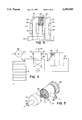
- FIG. 1 is a perspective view of a preferred embodiment of the scrubber system according to the invention.
- FIG. 2 is a perspective view of an embodiment of a container therefor
- FIG. 3 is a perspective view of a further embodiment of the scrubber
- FIG. 4 is a diagram of a scrubber system provided with air flow reversal means
- FIG. 5 is a perspective, fragmented view of a cylindrical embodiment of the scrubber.
- FIG. 1 a scrubber system 10 for removing carbon dioxide from a metal-air battery, such as the zinc-air battery 12 shown. This is achieved by removing said carbon dioxide from the air which is fed to the battery 12 for use as an oxidant.
- a scrubber housing 14 is provided with a gas inlet 16, through which air enters, containing, as is normal, about 0.04% of CO 2 . Housing 14 is also provided with a gas outlet 18, through which purified air passes on its way to be used in the battery 12.
- three gas-permeable containers 20a, 20b, 20c are supported in series across the flow path of gas, i.e., air, which enters inlet 16, passes in series through all the containers 20, and exits the scubber housing 14 through the outlet 18.
- gas i.e., air
- Each of the containers 20 holds a CO 2 -absorbent material 22.
- the CO 2 -absorbent material comprises granular alkali metal hydroxide.
- a granule size of between 1 and 2 millimeters diameter provides a suitable compromise between the conflicting requirements of providing a large surface area and of minimizing the pressure drop of the gas flow.
- the CO 2 -absorbent material 22 comprises aqueous alkali metal hydroxide absorbed on a porous carrier.
- the containers 20 are individually independently removable from said series, so that a container holding material 22 which is chemically exhausted may be removed and replaced by a fresh container.
- the arrangement allows the individual removal from said series of a first container 20a closest to the gas inlet 16, and the repositioning of a second container from said series in the place of the container 20a.
- the first container 20a processes air which still retains its full charge of CO 2 , it is this first container 20a which will first be chemically exhausted.
- the air entering the container 20b will already have had a substantial part of its original CO 2 content removed, and thus container 20b will therefore be able to continue functioning after exhaustion of container 20a.
- the third container 20c can be repositioned in place of the second container 20b, upon repositioning of the second container 20b in place of the first container 20a, and a new container positioned in place of the third container 20c.
- FIG. 1 there is also shown housing 14 wherein three containers 20 are arranged as a vertical stack 26.
- Each lower container 20a, 20b directly supports an upper container.
- a sufficient degree of air sealing between vertically-adjacent containers is achieved by using the weight of the full upper container 20c as a sealing force.
- Housing 14 is provided with a lower side opening 26 to allow removal of the lowest container 20a.
- An upper side opening 28 allows insertion of an upper container 20c.
- Restricter means 28 are provided for the retention in framework 24 of the intermediate container 20b.
- Container 20 is provided with two major opposite faces 32, which are air porous. A large number of apertures 34 are provided on each face 32, the apertures 34 being smaller than the size of the granules comprising the material 22. Handles 36 are provided for convenience of withdrawal of the containers 20 from framework 24.
- a blower 38 powered by the battery 12, takes in air from the atmosphere and forces this air through the scrubber system 10, where CO 2 is removed. The purified air is then distributed to the cathodes of the individual battery cells and exits from the battery 12.
- the battery is further provided with an air humidification unit 40 and a thermal management controller 42.
- FIG. 2 there is seen a container 20, as described above, further comprising an attached seal element 44, configured for reducing air leakage between adjoining containers.
- the seal element 44 is advantageously made of a low-friction elastomer, so that withdrawal of a container may be effected without excessive seal frictional resistance.
- FIG. 3 shows a rack 46, supporting a series of containers 48 in contacting horizontal formation.
- Each container is provided, on a first side 50, with a male connector element 52, and on an opposite second side 54, with a corresponding female connector element 56.
- the sides 50, 54 have screens 55, sufficiently fine to retain CO 2 -absorbent material 22.
- the containers 48 form a substantially gas-tight series.
- the advantage of the horizontal series lies in that the containers 48 are easier to disconnect for purposes of replacement, as the series can be broken at any location by sliding the containers 48 along the rack 46.
- FIG. 4 depicts a further embodiment of a scrubber system 58.
- An air blower 38 having an outlet port 60, is connected to one port 62 of a four-way air valve 64.
- the remaining three ports 66, 68, 70 of the valve 64 are respectively in fluid connection with both gas ports 16, 18 of the scrubber housing 14, and with the air inlet port 72 of the metal-air battery 12.
- the scrubber is used until its output contains an unacceptably high level of CO 2 , for example, 0.03%, resulting from chemical exhaustion of granules 22 near the scrubber air inlet 16.
- the valve 64 is then operated, either by hand or by means of an automatic control, and the flow of air through the scrubber is thereby reversed. Due to air flow reversal, the granules which were previously adjacent to the scrubber outlet 18 and are therefore still chemically active, are now adjacent to the air inlet and now act to absorb CO 2 . Consequently, the operating life of the scrubber system is extended by a factor of about 1.8.
- a scrubber in the form of a removable tubular container 74.
- An air inlet 76 is connected through an end face 78 to an inner perforated tube 80, which is concentric to the outer cylindrical wall 82.
- CO 2 -absorbent material 22 allowing passage of air, is contained in the space between the inner and outer walls.
- An outlet 84 for purified air is connected to the outer wall 82.
- a removable sealing cap 86 is provided at one end of the container 74. Removal of the cap 86 allows emptying of container 74 of exhausted material 22 and refilling thereof with fresh material 22. Exhausted material 22 in small quantities is discarded; large quantities are, for economic and environmental reasons, chemically recharged for reuse.
- the invention also provides a method for maximizing the effective life and utilization of CO 2 -absorbent material in a scrubber system for removing carbon dioxide from a metal-air battery or fuel cell, comprising:
- Step A providing, in a metal-air battery, a housing including a gas inlet and a gas outlet, and a plurality of gas-permeable containers supported in series across the flow path of gas entering said inlet and exiting said outlet, each of said containers holding a CO 2 -absorbent material and being independently removable from said series;
- Step B removing from said series, after a predetermined amount of use of said system, a first container closest to said gas inlet, and repositioning a second container in the place of the first container.
- Step A providing, in a metal-air battery, a sub-compartmentalized system wherein there are three separately removable and repositionable, gas-permeable containers;
- Step B removing from said series, after a predetermined amount of use of said system, a first container closest to said gas inlet, and repositioning a second container in the place of the first container;
- Step C repositioning a third container from said series in the place of said second container
- Step D positioning a new container, holding fresh CO 2 -absorbent material, in the place of said third container.
- Step E Regenerating and repacking spent CO 2 -absorbent material from said first container, for reuse in said scrubber system.
- Regeneration of the material has ecological advantages and, where large quantities of containers are collected, will also be of economic advantage.
- Step A is inserted between Step A and Step B:
- Step A-1 After partial utilization of the CO 2 -absorbent material, air feed conduits connected to said inlet and said outlet are manually disconnected by the user and are then exchange-reconnected thereto.
Abstract
Description
2KOH+CO.sub.2 =K.sub.2 CO.sub.3 +H.sub.2 O (1)
2MOH+CO.sub.2 =M.sub.2 CO.sub.3 +H.sub.2 O (2)
M.sub.2 CO.sub.3 =M.sub.2 O+CO.sub.2 ( 3)
M.sub.2 O+H.sub.2 O=2MOH (4)
M.sub.2 CO.sub.3 +CaO+H.sub.2 O=2MOH+CaCO.sub.3 ( 5)
M.sub.2 CO.sub.3 +Ba(OH).sub.2 =2MOH+BaCO.sub.3 ( 6)
Claims (11)
Priority Applications (2)
| Application Number | Priority Date | Filing Date | Title |
|---|---|---|---|
| US08/210,333 US5595949A (en) | 1994-03-18 | 1994-03-18 | Scrubber system for removing carbon dioxide from a metal-air or fuel cell battery |
| EP95301398A EP0677883A1 (en) | 1994-03-18 | 1995-03-03 | Scrubber system for removing carbon dioxide from a metal-air or fuel cell battery |
Applications Claiming Priority (1)
| Application Number | Priority Date | Filing Date | Title |
|---|---|---|---|
| US08/210,333 US5595949A (en) | 1994-03-18 | 1994-03-18 | Scrubber system for removing carbon dioxide from a metal-air or fuel cell battery |
Publications (1)
| Publication Number | Publication Date |
|---|---|
| US5595949A true US5595949A (en) | 1997-01-21 |
Family
ID=22782492
Family Applications (1)
| Application Number | Title | Priority Date | Filing Date |
|---|---|---|---|
| US08/210,333 Expired - Fee Related US5595949A (en) | 1994-03-18 | 1994-03-18 | Scrubber system for removing carbon dioxide from a metal-air or fuel cell battery |
Country Status (2)
| Country | Link |
|---|---|
| US (1) | US5595949A (en) |
| EP (1) | EP0677883A1 (en) |
Cited By (45)
| Publication number | Priority date | Publication date | Assignee | Title |
|---|---|---|---|---|
| US6228150B1 (en) * | 1996-11-25 | 2001-05-08 | Armstrong Medical Limited | Carbon dioxide absorbent in anaesthesiology |
| WO2002072241A1 (en) | 2001-03-12 | 2002-09-19 | Motorola, Inc., A Corporation Of The State Of Delaware | Fuel cell system having a replaceable getter element for purifying the fuel supply |
| US6489052B1 (en) * | 1999-11-18 | 2002-12-03 | Plug Power Inc. | Fuel cell air purification subsystem |
| US20040065205A1 (en) * | 2002-10-03 | 2004-04-08 | Nalette Timothy A. | Encapsulated CO2 H2O sorbent |
| WO2004042857A1 (en) * | 2002-11-05 | 2004-05-21 | Zakrytoe Aktsionernoe Obschestvo 'independent Power Technologies' | Method and device for purifying air for fuel cells |
| US20040157095A1 (en) * | 2000-12-29 | 2004-08-12 | Rolf Bruck | Method for operating a fuel cell system which can be used in a vehicle, and associated fuel cell system |
| US20040191598A1 (en) * | 2003-03-24 | 2004-09-30 | Ion America Corporation | SORFC power and oxygen generation method and system |
| US20050022670A1 (en) * | 2000-09-12 | 2005-02-03 | Donaldson Company, Inc. | Air filter assembly for low temperature catalytic processes |
| US6866702B2 (en) * | 2003-01-29 | 2005-03-15 | International Environmental Conservative Association, Inc. | Device for absorbing carbon dioxide, and a method for absorbing carbon dioxide |
| US20050232858A1 (en) * | 2003-11-26 | 2005-10-20 | Hampden-Smith Mark J | Fuel reformer catalyst and absorbent materials |
| US20060096456A1 (en) * | 2002-07-05 | 2006-05-11 | Daimlerchrysler Ag | Method and arrangement for purification of gases for supply to operate a fuel cell by the application of physical and chemical filters |
| US20070089608A1 (en) * | 2003-06-11 | 2007-04-26 | Tomohiro Yabu | Humidity controller apparatus |
| US20070141430A1 (en) * | 2005-12-21 | 2007-06-21 | Qunjian Huang | Gas scrubber and method related thereto |
| US20070141440A1 (en) * | 2005-12-21 | 2007-06-21 | General Electric Company | Cylindrical structure fuel cell |
| US20070141462A1 (en) * | 2005-12-21 | 2007-06-21 | General Electric Company | Method and apparatus for reducing water loss |
| US20070141450A1 (en) * | 2005-12-21 | 2007-06-21 | General Electric Company | Rechargeable fuel cell with double cathode |
| US20070141456A1 (en) * | 2005-12-21 | 2007-06-21 | General Electric Company | Bipolar membrane |
| US20070141431A1 (en) * | 2005-12-21 | 2007-06-21 | General Electric Company | Fuel cell closed structure |
| US20070141473A1 (en) * | 2005-12-21 | 2007-06-21 | General Electric Company | Integrated membrane electrode assembly and method related thereto |
| US20070141464A1 (en) * | 2005-12-21 | 2007-06-21 | Qunjian Huang | Porous metal hydride electrode |
| US20070141432A1 (en) * | 2005-12-21 | 2007-06-21 | General Electric Company | Third electrode frame structure and method related thereto |
| US20070157815A1 (en) * | 2004-01-16 | 2007-07-12 | Yasunari Arai | Gas-removing devices and air supply systems having the gas-removing devices |
| US7267811B2 (en) | 2003-11-26 | 2007-09-11 | Cabot Corporation | Fuel reformer catalyst and absorbent materials |
| US20070269689A1 (en) * | 2006-05-19 | 2007-11-22 | Samsung Sdi Co., Ltd. | Integrated fuel recycling module for use in fuel cell system and fuel cell system using the same |
| US20080145721A1 (en) * | 2006-12-14 | 2008-06-19 | General Electric Company | Fuel cell apparatus and associated method |
| US20080216653A1 (en) * | 2007-03-09 | 2008-09-11 | Strata Products (Usa), Inc. | Apparatus, system and method for cleaning air |
| US20080314660A1 (en) * | 2005-02-01 | 2008-12-25 | Damian Davies | Detachable Fuel Cell Power Unit For Vehicle Applications |
| US20090068502A1 (en) * | 2007-05-21 | 2009-03-12 | Corrigan Dennis A | Remote emergency power unit having electrochemically regenerated carbon dioxide scrubber |
| US20090104098A1 (en) * | 2007-10-19 | 2009-04-23 | Uday Singh | Method and apparatus for the removal of carbon dioxide from a gas stream |
| US20090258264A1 (en) * | 2008-04-14 | 2009-10-15 | Ballard Gary L | Cartridge adsorber system for removing hydrogen sulfide from reformate |
| US20100074828A1 (en) * | 2008-01-28 | 2010-03-25 | Fluegen, Inc. | Method and Apparatus for the Removal of Carbon Dioxide from a Gas Stream |
| WO2015179275A1 (en) * | 2014-05-19 | 2015-11-26 | Gencell Ltd. | Scrubbing device for gas used in a fuel cell and method of scrubbing gas using the device |
| US20160344080A1 (en) * | 2015-05-19 | 2016-11-24 | Samsung Electronics Co., Ltd. | Metal air battery having air purification module and and method of operating the metal air battery |
| US20170018826A1 (en) * | 2015-07-14 | 2017-01-19 | Samsung Electronics Co., Ltd. | Metal air battery and method of operating the same |
| WO2018187561A1 (en) * | 2017-04-06 | 2018-10-11 | Jaramillo Mateo Cristian | Refuelable battery for the electric grid and method of using thereof |
| WO2018236423A1 (en) * | 2017-06-22 | 2018-12-27 | Allied Healthcare Products, Inc. | Portable carbon dioxide absorption system |
| US10193154B2 (en) | 2013-01-31 | 2019-01-29 | Medtronic, Inc. | Cathode composition for primary battery |
| JP2019521497A (en) * | 2016-07-22 | 2019-07-25 | ナントエナジー,インク. | Water and carbon dioxide management system in the electrochemical cell |
| WO2020124051A1 (en) | 2018-12-14 | 2020-06-18 | Energizer Brands, Llc | Zinc-air electrochemical cells with carbon dioxide scavangers |
| WO2020139881A1 (en) * | 2018-12-27 | 2020-07-02 | Energizer Brands, Llc | Metal-air cells with minimal air access |
| US20220176307A1 (en) * | 2019-04-11 | 2022-06-09 | Klaus Lackner | System, method, and device for small scale carbon dioxide collection |
| US11552290B2 (en) | 2018-07-27 | 2023-01-10 | Form Energy, Inc. | Negative electrodes for electrochemical cells |
| US11575168B2 (en) | 2021-07-01 | 2023-02-07 | Energizer Brands, Llc | Metal-air cells with minimal air access |
| US11611115B2 (en) | 2017-12-29 | 2023-03-21 | Form Energy, Inc. | Long life sealed alkaline secondary batteries |
| US11949129B2 (en) | 2019-10-04 | 2024-04-02 | Form Energy, Inc. | Refuelable battery for the electric grid and method of using thereof |
Families Citing this family (8)
| Publication number | Priority date | Publication date | Assignee | Title |
|---|---|---|---|---|
| GB2305139A (en) * | 1995-09-12 | 1997-04-02 | Electric Fuel | Coated absorbent particles for a carbon dioxide scrubber system |
| DE19921816C1 (en) * | 1999-05-11 | 2000-10-26 | Andre Peine | Fuel cell system has fuel dell device combined with fuel reservoir and device for receiving waste product in form of filter or ion exchanger |
| CA2352626A1 (en) | 2001-07-12 | 2003-01-12 | Co2 Solution Inc. | Coupling for linking a hydrogen fuel cell to an enzyme bioreactor for processing and sequestering co2 |
| US20060222945A1 (en) * | 2005-04-01 | 2006-10-05 | Bowden William L | Battery cathodes |
| KR100684806B1 (en) | 2005-11-17 | 2007-02-20 | 삼성에스디아이 주식회사 | Carbon dioxide remover for direct oxydation fuel cell and fuel cell system with the same |
| JP5862979B2 (en) * | 2010-07-22 | 2016-02-16 | ユニバーシティ オブ サザン カリフォルニア | Iron air rechargeable battery |
| CN103597655B (en) | 2011-06-15 | 2017-08-04 | 南加利福尼亚大学 | High efficiency iron electrode and the additive used in chargeable iron-based battery |
| CN110721376B (en) * | 2019-10-25 | 2021-04-20 | 吉林大学 | Sodium lime utility detection device for anesthesia machine |
Citations (11)
| Publication number | Priority date | Publication date | Assignee | Title |
|---|---|---|---|---|
| FR1583419A (en) * | 1967-02-15 | 1969-10-31 | ||
| US3830632A (en) * | 1969-07-23 | 1974-08-20 | C Guzay | Carbon dioxide absorber apparatus |
| FR2230396A1 (en) * | 1973-05-22 | 1974-12-20 | Siemens Ag | |
| US3909206A (en) * | 1974-04-10 | 1975-09-30 | United Technologies Corp | High performance carbon dioxide scrubber |
| FR2290239A1 (en) * | 1974-11-08 | 1976-06-04 | Inst Francais Du Petrole | Decarbonating a gas for use in fuel cells - by passing it through dry lithium hydroxide air and powder being preheated |
| US3990912A (en) * | 1972-07-17 | 1976-11-09 | United Technologies Corporation | Electrolyte regeneration in a fuel cell stack |
| GB2030886A (en) * | 1978-10-06 | 1980-04-16 | Medishield Corp Ltd | Filter canister |
| WO1984002283A1 (en) * | 1982-12-08 | 1984-06-21 | Lindstroem Ab Olle | Means and procedure for removal of carbon dioxide |
| JPS6035470A (en) * | 1983-08-05 | 1985-02-23 | Fuji Electric Corp Res & Dev Ltd | Gas supply method of fuel cell |
| EP0201468A1 (en) * | 1985-05-09 | 1986-11-12 | Icor Ab | A device for removing carbon dioxide from a gas mixture |
| JPS63241877A (en) * | 1987-03-27 | 1988-10-07 | Kawasaki Heavy Ind Ltd | Processing method for waste gas from fuel cell |
-
1994
- 1994-03-18 US US08/210,333 patent/US5595949A/en not_active Expired - Fee Related
-
1995
- 1995-03-03 EP EP95301398A patent/EP0677883A1/en not_active Withdrawn
Patent Citations (12)
| Publication number | Priority date | Publication date | Assignee | Title |
|---|---|---|---|---|
| FR1583419A (en) * | 1967-02-15 | 1969-10-31 | ||
| US3830632A (en) * | 1969-07-23 | 1974-08-20 | C Guzay | Carbon dioxide absorber apparatus |
| US3990912A (en) * | 1972-07-17 | 1976-11-09 | United Technologies Corporation | Electrolyte regeneration in a fuel cell stack |
| FR2230396A1 (en) * | 1973-05-22 | 1974-12-20 | Siemens Ag | |
| US4047894A (en) * | 1973-05-22 | 1977-09-13 | Siemens Aktiengesellschaft | Removing carbon dioxide from the air |
| US3909206A (en) * | 1974-04-10 | 1975-09-30 | United Technologies Corp | High performance carbon dioxide scrubber |
| FR2290239A1 (en) * | 1974-11-08 | 1976-06-04 | Inst Francais Du Petrole | Decarbonating a gas for use in fuel cells - by passing it through dry lithium hydroxide air and powder being preheated |
| GB2030886A (en) * | 1978-10-06 | 1980-04-16 | Medishield Corp Ltd | Filter canister |
| WO1984002283A1 (en) * | 1982-12-08 | 1984-06-21 | Lindstroem Ab Olle | Means and procedure for removal of carbon dioxide |
| JPS6035470A (en) * | 1983-08-05 | 1985-02-23 | Fuji Electric Corp Res & Dev Ltd | Gas supply method of fuel cell |
| EP0201468A1 (en) * | 1985-05-09 | 1986-11-12 | Icor Ab | A device for removing carbon dioxide from a gas mixture |
| JPS63241877A (en) * | 1987-03-27 | 1988-10-07 | Kawasaki Heavy Ind Ltd | Processing method for waste gas from fuel cell |
Cited By (82)
| Publication number | Priority date | Publication date | Assignee | Title |
|---|---|---|---|---|
| US6228150B1 (en) * | 1996-11-25 | 2001-05-08 | Armstrong Medical Limited | Carbon dioxide absorbent in anaesthesiology |
| US6489052B1 (en) * | 1999-11-18 | 2002-12-03 | Plug Power Inc. | Fuel cell air purification subsystem |
| US20050022670A1 (en) * | 2000-09-12 | 2005-02-03 | Donaldson Company, Inc. | Air filter assembly for low temperature catalytic processes |
| US7758674B2 (en) | 2000-09-12 | 2010-07-20 | Donaldson Company, Inc. | Air filter assembly for low temperature catalytic processes |
| US7101419B2 (en) * | 2000-09-12 | 2006-09-05 | Donaldson Company, Inc. | Air filter assembly for low temperature catalytic processes |
| US20040157095A1 (en) * | 2000-12-29 | 2004-08-12 | Rolf Bruck | Method for operating a fuel cell system which can be used in a vehicle, and associated fuel cell system |
| WO2002072241A1 (en) | 2001-03-12 | 2002-09-19 | Motorola, Inc., A Corporation Of The State Of Delaware | Fuel cell system having a replaceable getter element for purifying the fuel supply |
| US6689194B2 (en) * | 2001-03-12 | 2004-02-10 | Motorola, Inc | Fuel cell system having a replaceable getter element for purifying the fuel supply |
| US20060096456A1 (en) * | 2002-07-05 | 2006-05-11 | Daimlerchrysler Ag | Method and arrangement for purification of gases for supply to operate a fuel cell by the application of physical and chemical filters |
| US7449046B2 (en) * | 2002-07-05 | 2008-11-11 | Daimler Ag | Method and arrangement for purifying gases fed to a fuel cell by removing operational unfavorable constituents |
| US20040065205A1 (en) * | 2002-10-03 | 2004-04-08 | Nalette Timothy A. | Encapsulated CO2 H2O sorbent |
| US6797043B2 (en) * | 2002-10-03 | 2004-09-28 | Hamilton Sundstrand | Encapsulated CO2 H2O sorbent |
| US20060123989A1 (en) * | 2002-11-05 | 2006-06-15 | Karichev Ziya R | Method and device for purifying air for fuel cells |
| WO2004042857A1 (en) * | 2002-11-05 | 2004-05-21 | Zakrytoe Aktsionernoe Obschestvo 'independent Power Technologies' | Method and device for purifying air for fuel cells |
| US8409331B2 (en) * | 2002-11-05 | 2013-04-02 | Obschestvo S Ogranichennoi Otvetstvennostiyu “Intensis” | Method and device for purifying air for fuel cells |
| US6866702B2 (en) * | 2003-01-29 | 2005-03-15 | International Environmental Conservative Association, Inc. | Device for absorbing carbon dioxide, and a method for absorbing carbon dioxide |
| US7572530B2 (en) | 2003-03-24 | 2009-08-11 | Bloom Energy Corporation | SORFC power and oxygen generation method and system |
| US20060204798A1 (en) * | 2003-03-24 | 2006-09-14 | Ion America Corporation | SORFC power and oxygen generation method and system |
| US20040191598A1 (en) * | 2003-03-24 | 2004-09-30 | Ion America Corporation | SORFC power and oxygen generation method and system |
| US7045238B2 (en) * | 2003-03-24 | 2006-05-16 | Ion America Corporation | SORFC power and oxygen generation method and system |
| US20070089608A1 (en) * | 2003-06-11 | 2007-04-26 | Tomohiro Yabu | Humidity controller apparatus |
| US7410533B2 (en) * | 2003-06-11 | 2008-08-12 | Daikin Industries, Ltd. | Humidity controller apparatus |
| US20050232858A1 (en) * | 2003-11-26 | 2005-10-20 | Hampden-Smith Mark J | Fuel reformer catalyst and absorbent materials |
| US7267811B2 (en) | 2003-11-26 | 2007-09-11 | Cabot Corporation | Fuel reformer catalyst and absorbent materials |
| US7264788B2 (en) | 2003-11-26 | 2007-09-04 | Cabot Corporation | Fuel reformer catalyst and absorbent materials |
| US7520921B2 (en) * | 2004-01-16 | 2009-04-21 | Toyota Boshoku Kabushiki Kaisha | Gas-removing devices and air supply systems having the gas-removing devices |
| US20070157815A1 (en) * | 2004-01-16 | 2007-07-12 | Yasunari Arai | Gas-removing devices and air supply systems having the gas-removing devices |
| US8011462B2 (en) * | 2005-02-01 | 2011-09-06 | Damian Davies | Detachable fuel cell power unit for vehicle applications |
| US20080314660A1 (en) * | 2005-02-01 | 2008-12-25 | Damian Davies | Detachable Fuel Cell Power Unit For Vehicle Applications |
| US20070141473A1 (en) * | 2005-12-21 | 2007-06-21 | General Electric Company | Integrated membrane electrode assembly and method related thereto |
| US20070141440A1 (en) * | 2005-12-21 | 2007-06-21 | General Electric Company | Cylindrical structure fuel cell |
| US20070141430A1 (en) * | 2005-12-21 | 2007-06-21 | Qunjian Huang | Gas scrubber and method related thereto |
| US20070141432A1 (en) * | 2005-12-21 | 2007-06-21 | General Electric Company | Third electrode frame structure and method related thereto |
| US7887944B2 (en) | 2005-12-21 | 2011-02-15 | General Electric Company | Integrated membrane electrode assembly and method related thereto |
| US20070141464A1 (en) * | 2005-12-21 | 2007-06-21 | Qunjian Huang | Porous metal hydride electrode |
| US20070141431A1 (en) * | 2005-12-21 | 2007-06-21 | General Electric Company | Fuel cell closed structure |
| US20070141462A1 (en) * | 2005-12-21 | 2007-06-21 | General Electric Company | Method and apparatus for reducing water loss |
| US20070141456A1 (en) * | 2005-12-21 | 2007-06-21 | General Electric Company | Bipolar membrane |
| US20070141450A1 (en) * | 2005-12-21 | 2007-06-21 | General Electric Company | Rechargeable fuel cell with double cathode |
| US20070269689A1 (en) * | 2006-05-19 | 2007-11-22 | Samsung Sdi Co., Ltd. | Integrated fuel recycling module for use in fuel cell system and fuel cell system using the same |
| US20080145721A1 (en) * | 2006-12-14 | 2008-06-19 | General Electric Company | Fuel cell apparatus and associated method |
| US9162176B2 (en) | 2007-03-09 | 2015-10-20 | Strata Products Worldwide, Llc | Apparatus and method for affecting air |
| US20080216653A1 (en) * | 2007-03-09 | 2008-09-11 | Strata Products (Usa), Inc. | Apparatus, system and method for cleaning air |
| US8506681B2 (en) | 2007-03-09 | 2013-08-13 | Strata Products Worldwide, Llc | Apparatus, system and method for cleaning air |
| RU2444387C2 (en) * | 2007-03-09 | 2012-03-10 | СТРАТА ПРОДАКТС ВОРЛДВАЙД, ЭлЭлСи | Device, system and method of air cleaning |
| US20090068502A1 (en) * | 2007-05-21 | 2009-03-12 | Corrigan Dennis A | Remote emergency power unit having electrochemically regenerated carbon dioxide scrubber |
| US20090104098A1 (en) * | 2007-10-19 | 2009-04-23 | Uday Singh | Method and apparatus for the removal of carbon dioxide from a gas stream |
| US7964170B2 (en) | 2007-10-19 | 2011-06-21 | Fluegen, Inc. | Method and apparatus for the removal of carbon dioxide from a gas stream |
| US20100074828A1 (en) * | 2008-01-28 | 2010-03-25 | Fluegen, Inc. | Method and Apparatus for the Removal of Carbon Dioxide from a Gas Stream |
| US20090258264A1 (en) * | 2008-04-14 | 2009-10-15 | Ballard Gary L | Cartridge adsorber system for removing hydrogen sulfide from reformate |
| US7896952B2 (en) * | 2008-04-14 | 2011-03-01 | Delphi Technologies, Inc. | Cartridge adsorber system for removing hydrogen sulfide from reformate |
| US10193154B2 (en) | 2013-01-31 | 2019-01-29 | Medtronic, Inc. | Cathode composition for primary battery |
| US10530001B2 (en) | 2014-05-19 | 2020-01-07 | Gencell Ltd. | Scrubbing device for gas used in a fuel cell and method of scrubbing gas using the device |
| WO2015179275A1 (en) * | 2014-05-19 | 2015-11-26 | Gencell Ltd. | Scrubbing device for gas used in a fuel cell and method of scrubbing gas using the device |
| US20160344080A1 (en) * | 2015-05-19 | 2016-11-24 | Samsung Electronics Co., Ltd. | Metal air battery having air purification module and and method of operating the metal air battery |
| US10074884B2 (en) * | 2015-05-19 | 2018-09-11 | Samsung Electronics Co., Ltd. | Metal air battery having air purification module and method of operating the metal air battery |
| US20170018826A1 (en) * | 2015-07-14 | 2017-01-19 | Samsung Electronics Co., Ltd. | Metal air battery and method of operating the same |
| US11127997B2 (en) * | 2015-07-14 | 2021-09-21 | Samsung Electronics Co., Ltd. | Metal air battery and method of operating the same |
| US11664547B2 (en) | 2016-07-22 | 2023-05-30 | Form Energy, Inc. | Moisture and carbon dioxide management system in electrochemical cells |
| JP2019521497A (en) * | 2016-07-22 | 2019-07-25 | ナントエナジー,インク. | Water and carbon dioxide management system in the electrochemical cell |
| US11018387B2 (en) * | 2016-07-22 | 2021-05-25 | Form Energy, Inc. | Moisture and carbon dioxide management system in electrochemical cells |
| US11394035B2 (en) | 2017-04-06 | 2022-07-19 | Form Energy, Inc. | Refuelable battery for the electric grid and method of using thereof |
| WO2018187561A1 (en) * | 2017-04-06 | 2018-10-11 | Jaramillo Mateo Cristian | Refuelable battery for the electric grid and method of using thereof |
| AU2019226247B2 (en) * | 2017-06-22 | 2021-06-24 | Allied Healthcare Products, Inc. | Portable carbon dioxide absorption system |
| AU2018288972B2 (en) * | 2017-06-22 | 2019-10-10 | Allied Healthcare Products, Inc. | Portable carbon dioxide absorption system |
| JP2020514045A (en) * | 2017-06-22 | 2020-05-21 | アライド ヘルスケア プロダクツ、インコーポレーテッドAllied Healthcare Products, Inc. | Portable carbon dioxide absorption system |
| RU2736764C1 (en) * | 2017-06-22 | 2020-11-19 | Эллайд Хелткэа Продактс, Инк. | Portable carbon dioxide absorption unit |
| US10864480B2 (en) * | 2017-06-22 | 2020-12-15 | Allied Healthcare Products, Inc. | Portable carbon dioxide absorption system |
| US10518214B2 (en) | 2017-06-22 | 2019-12-31 | Allied Healthcare Products, Inc. | Portable carbon dioxide absorption system |
| WO2018236423A1 (en) * | 2017-06-22 | 2018-12-27 | Allied Healthcare Products, Inc. | Portable carbon dioxide absorption system |
| AU2018288972B9 (en) * | 2017-06-22 | 2020-02-06 | Allied Healthcare Products, Inc. | Portable carbon dioxide absorption system |
| US11611115B2 (en) | 2017-12-29 | 2023-03-21 | Form Energy, Inc. | Long life sealed alkaline secondary batteries |
| US11552290B2 (en) | 2018-07-27 | 2023-01-10 | Form Energy, Inc. | Negative electrodes for electrochemical cells |
| WO2020124051A1 (en) | 2018-12-14 | 2020-06-18 | Energizer Brands, Llc | Zinc-air electrochemical cells with carbon dioxide scavangers |
| EP3895241A4 (en) * | 2018-12-14 | 2022-12-21 | Energizer Brands, LLC | Zinc-air electrochemical cells with carbon dioxide scavengers |
| US11031644B2 (en) | 2018-12-27 | 2021-06-08 | Energizer Brands, Llc | Metal-air cells with minimal air access |
| US11502356B2 (en) | 2018-12-27 | 2022-11-15 | Energizer Brands, Llc | Metal-air cells with minimal air access |
| WO2020139881A1 (en) * | 2018-12-27 | 2020-07-02 | Energizer Brands, Llc | Metal-air cells with minimal air access |
| US20220176307A1 (en) * | 2019-04-11 | 2022-06-09 | Klaus Lackner | System, method, and device for small scale carbon dioxide collection |
| US11949129B2 (en) | 2019-10-04 | 2024-04-02 | Form Energy, Inc. | Refuelable battery for the electric grid and method of using thereof |
| US11575168B2 (en) | 2021-07-01 | 2023-02-07 | Energizer Brands, Llc | Metal-air cells with minimal air access |
| US11848435B2 (en) | 2021-07-01 | 2023-12-19 | Energizer Brands, Llc | Metal-air cells with minimal air access |
Also Published As
| Publication number | Publication date |
|---|---|
| EP0677883A1 (en) | 1995-10-18 |
Similar Documents
| Publication | Publication Date | Title |
|---|---|---|
| US5595949A (en) | Scrubber system for removing carbon dioxide from a metal-air or fuel cell battery | |
| US3511712A (en) | Process of removing carbon dioxide from gas streams using fuel cell | |
| US3911080A (en) | Air pollution control | |
| US11466372B2 (en) | Electrochemical carbon dioxide converter and liquid regenerator | |
| US3847672A (en) | Fuel cell with gas separator | |
| US8177946B2 (en) | Electrochemical formation of hydroxide for enhancing carbon dioxide and acid gas uptake by a solution | |
| US3475122A (en) | Recovery of sulfur dioxide from gas streams | |
| EP3572140B1 (en) | Electrochemical carbon dioxide converter and liquid regenerator | |
| US7267710B2 (en) | Method of and apparatus for regenerating adsorbent | |
| US20090220388A1 (en) | Breathing air maintenance and recycle | |
| EP1469544A1 (en) | Method of operating a fuel cell, air purifying apparatus and fuel cell | |
| JPH01307173A (en) | Electrolyte regenerating device for redox flow battery | |
| US20060275193A1 (en) | Electrochemical process for decomposition of hydrogen sulfide and production of sulfur | |
| EP1355372B1 (en) | Apparatus and method for gas generation in a fuel cell | |
| RU2491109C1 (en) | Air cleaner for sealed manned objects | |
| US3519488A (en) | Carbon dioxide absorber means and fuel cell to regenerate absorbent | |
| US20080274384A1 (en) | Self-regulating hydrogen generator for use with a fuel cell | |
| GB2305139A (en) | Coated absorbent particles for a carbon dioxide scrubber system | |
| US10530001B2 (en) | Scrubbing device for gas used in a fuel cell and method of scrubbing gas using the device | |
| US4693794A (en) | Process for manufacturing hydrogen peroxide electrolytically | |
| RU98938U1 (en) | INSTALLATION FOR CONCENTRATION OF CARBON DIOXIDE REMOVED FROM THE ATMOSPHERE (OPTIONS) | |
| JP2004327429A (en) | Fuel cell and air purifier for fuel cell | |
| KR200285466Y1 (en) | Portable alkaline fuel cell | |
| RU2393593C1 (en) | Procedure for purification of air from carbon dioxide for alkaline hydrogen-air fuel elements | |
| JP2020126709A (en) | Replenishing liquid for lead acid battery, lead acid battery replenishing liquid bottle product, maintenance method for lead acid battery, regeneration method for lead acid battery, and production method for replenishing liquid for lead acid battery |
Legal Events
| Date | Code | Title | Description |
|---|---|---|---|
| AS | Assignment |
Owner name: ELECTRIC FUEL (E.F.L.) LTD., ISRAEL Free format text: ASSIGNMENT OF ASSIGNORS INTEREST;ASSIGNORS:GOLDSTEIN, JONATHAN;HARATS, YEHUDA;SHARON, YUVAL;AND OTHERS;REEL/FRAME:006925/0904 Effective date: 19940221 |
|
| REMI | Maintenance fee reminder mailed | ||
| LAPS | Lapse for failure to pay maintenance fees | ||
| FP | Lapsed due to failure to pay maintenance fee |
Effective date: 20010121 |
|
| AS | Assignment |
Owner name: SMITHFIELD FIDUCIARY LLC, NEW YORK Free format text: SECURITY AGREEMENT;ASSIGNORS:ELECTRIC FUEL CORPORATION;ELECTRIC FUEL TRANSPORATION CORP.;ELECTRIC FUEL B.V.;AND OTHERS;REEL/FRAME:013746/0842 Effective date: 20021231 Owner name: VERTICAL VENTURES, NEW YORK Free format text: SECURITY AGREEMENT;ASSIGNORS:ELECTRIC FUEL CORPORATION;ELECTRIC FUEL TRANSPORATION CORP.;ELECTRIC FUEL B.V.;AND OTHERS;REEL/FRAME:013746/0842 Effective date: 20021231 Owner name: ZLP MASTER TECHNOLOGY FUND, LTD, NEW YORK Free format text: SECURITY AGREEMENT;ASSIGNORS:ELECTRIC FUEL CORPORATION;ELECTRIC FUEL TRANSPORATION CORP.;ELECTRIC FUEL B.V.;AND OTHERS;REEL/FRAME:013746/0842 Effective date: 20021231 |
|
| AS | Assignment |
Owner name: FIFTH THIRD BANK, AN OHIO BANKING CORPORATION, MIC Free format text: SECURITY INTEREST;ASSIGNORS:FAAC INCORPORATED;AROTECH CORPORATION;ELECTRIC FUEL BATTERY CORPORATION;REEL/FRAME:032585/0408 Effective date: 20140326 |
|
| STCH | Information on status: patent discontinuation |
Free format text: PATENT EXPIRED DUE TO NONPAYMENT OF MAINTENANCE FEES UNDER 37 CFR 1.362 |
|
| AS | Assignment |
Owner name: FAAC INCORPORATED, MICHIGAN Free format text: RELEASE BY SECURED PARTY;ASSIGNOR:FIFTH THIRD BANK;REEL/FRAME:054745/0433 Effective date: 20201104 Owner name: AROTECH CORPORATION, MICHIGAN Free format text: RELEASE BY SECURED PARTY;ASSIGNOR:FIFTH THIRD BANK;REEL/FRAME:054745/0433 Effective date: 20201104 Owner name: ELECTRIC FUEL BATTERY CORP, MICHIGAN Free format text: RELEASE BY SECURED PARTY;ASSIGNOR:FIFTH THIRD BANK;REEL/FRAME:054745/0433 Effective date: 20201104 |