JP2004363707A - Display method and display device - Google Patents
Display method and display device Download PDFInfo
- Publication number
- JP2004363707A JP2004363707A JP2003156953A JP2003156953A JP2004363707A JP 2004363707 A JP2004363707 A JP 2004363707A JP 2003156953 A JP2003156953 A JP 2003156953A JP 2003156953 A JP2003156953 A JP 2003156953A JP 2004363707 A JP2004363707 A JP 2004363707A
- Authority
- JP
- Japan
- Prior art keywords
- display
- item
- value
- circle
- displayed
- Prior art date
- Legal status (The legal status is an assumption and is not a legal conclusion. Google has not performed a legal analysis and makes no representation as to the accuracy of the status listed.)
- Pending
Links
- 238000000034 method Methods 0.000 title claims description 37
- 238000010586 diagram Methods 0.000 description 18
- 238000003384 imaging method Methods 0.000 description 16
- 230000008569 process Effects 0.000 description 11
- 230000008859 change Effects 0.000 description 10
- 230000007704 transition Effects 0.000 description 7
- 239000004973 liquid crystal related substance Substances 0.000 description 3
- 230000004048 modification Effects 0.000 description 3
- 238000012986 modification Methods 0.000 description 3
- 239000004065 semiconductor Substances 0.000 description 3
- 230000003287 optical effect Effects 0.000 description 2
- 230000035945 sensitivity Effects 0.000 description 2
- 239000003086 colorant Substances 0.000 description 1
- 238000012790 confirmation Methods 0.000 description 1
- 230000007423 decrease Effects 0.000 description 1
- 230000000694 effects Effects 0.000 description 1
- 230000006870 function Effects 0.000 description 1
- 230000007246 mechanism Effects 0.000 description 1
- 238000009751 slip forming Methods 0.000 description 1
Images


Classifications
-
- G—PHYSICS
- G06—COMPUTING; CALCULATING OR COUNTING
- G06F—ELECTRIC DIGITAL DATA PROCESSING
- G06F3/00—Input arrangements for transferring data to be processed into a form capable of being handled by the computer; Output arrangements for transferring data from processing unit to output unit, e.g. interface arrangements
- G06F3/01—Input arrangements or combined input and output arrangements for interaction between user and computer
- G06F3/048—Interaction techniques based on graphical user interfaces [GUI]
- G06F3/0481—Interaction techniques based on graphical user interfaces [GUI] based on specific properties of the displayed interaction object or a metaphor-based environment, e.g. interaction with desktop elements like windows or icons, or assisted by a cursor's changing behaviour or appearance
- G06F3/0482—Interaction with lists of selectable items, e.g. menus
-
- H—ELECTRICITY
- H04—ELECTRIC COMMUNICATION TECHNIQUE
- H04N—PICTORIAL COMMUNICATION, e.g. TELEVISION
- H04N23/00—Cameras or camera modules comprising electronic image sensors; Control thereof
- H04N23/60—Control of cameras or camera modules
- H04N23/62—Control of parameters via user interfaces
-
- H—ELECTRICITY
- H04—ELECTRIC COMMUNICATION TECHNIQUE
- H04N—PICTORIAL COMMUNICATION, e.g. TELEVISION
- H04N23/00—Cameras or camera modules comprising electronic image sensors; Control thereof
- H04N23/60—Control of cameras or camera modules
- H04N23/63—Control of cameras or camera modules by using electronic viewfinders
- H04N23/633—Control of cameras or camera modules by using electronic viewfinders for displaying additional information relating to control or operation of the camera
- H04N23/634—Warning indications
-
- H—ELECTRICITY
- H04—ELECTRIC COMMUNICATION TECHNIQUE
- H04N—PICTORIAL COMMUNICATION, e.g. TELEVISION
- H04N23/00—Cameras or camera modules comprising electronic image sensors; Control thereof
- H04N23/60—Control of cameras or camera modules
- H04N23/63—Control of cameras or camera modules by using electronic viewfinders
- H04N23/633—Control of cameras or camera modules by using electronic viewfinders for displaying additional information relating to control or operation of the camera
- H04N23/635—Region indicators; Field of view indicators
-
- H—ELECTRICITY
- H04—ELECTRIC COMMUNICATION TECHNIQUE
- H04N—PICTORIAL COMMUNICATION, e.g. TELEVISION
- H04N2101/00—Still video cameras
Landscapes
- Engineering & Computer Science (AREA)
- Multimedia (AREA)
- Signal Processing (AREA)
- General Engineering & Computer Science (AREA)
- Theoretical Computer Science (AREA)
- Human Computer Interaction (AREA)
- Physics & Mathematics (AREA)
- General Physics & Mathematics (AREA)
- Controls And Circuits For Display Device (AREA)
- User Interface Of Digital Computer (AREA)
- Digital Computer Display Output (AREA)
- Studio Devices (AREA)
Abstract
Description
【0001】
【発明の属する技術分野】
本発明は、例えばデジタルカメラの場合のシャッタ速度や絞り等の設定値のように、電子機器における設定値が複数段階存在する場合における、その設定値などの表示を行う表示方法及び表示装置に関する。
【0002】
【従来の技術】
従来、デジタルカメラやビデオカメラのように、撮影(撮像)した映像を表示させる表示パネルを備えた機器において、その表示パネルで、撮影した映像に重畳させて、各種設定状態を表示することが行われている。
【0003】
例えば、半導体メモリを内蔵したメモリカードに、撮影した映像をデジタルデータとして記録させるデジタルカメラの場合には、撮影時のシャッタ速度値や、絞りの値などを表示させるようにしたものがある。これらの値は、ユーザ操作で自由に設定できる場合と、カメラ側で自動的に設定される場合とがあるが、いずれの場合であっても、そのときの撮影状況に応じた設定状態を表示パネルに表示させることで、撮影操作を行う者に告知されて便利である。
【0004】
また、撮影モードなどの各種設定状態についても、表示パネルに同時に表示するようにしたものがある。
【0005】
特許文献1は、表示パネルに動作モードなどを表示させる場合の、従来の表示例について開示されている。
【0006】
【特許文献1】
特開平2002−163103号公報
【0007】
【発明が解決しようとする課題】
ところで、設定できる値やモードなどが複数存在する場合に、現在設定中の値やモードだけを表示パネルに表示させるようにすると、他にどのような値やモードが設定できるのか簡単には判らない問題がある。このため、現在設定中の値やモードだけでなく、設定可能な他の値やモードについても、表示パネルに同時に表示させることが考えられる。
【0008】
特許文献1に記載の処理の場合には、環状にモードの表示領域を設定させた上で、その環状に配置された個々のモード表示領域に、それぞれ別の動作モードを表示させて、その内の選択できるモード(メニュー)を中央に表示させるようにしてある。ところが、この特許文献1に記載された環状のモード表示では、手前側に配置された一部の表示領域だけで、動作モード(メニュー)が表示されており、その他の表示領域では文字などが表示されてなく、どのような選択が可能であるのか、何らかのキー操作などを行って、環状の表示を回転させる操作を行わないと、判らない問題がある。
【0009】
特に、上述したデジタルカメラの場合のシャッタ速度値や絞りの値などの撮影時に随時変更させる必要がある値については、設定可能な他の値が簡単に判った方が良い。このため、特許文献1に記載された環状のモード表示ではなく、全ての値の一覧を常時表示させる表示形態とすることが考えられるが、このように全ての値の一覧を常時表示させるようにすると、表示パネルに数字や文字などが多数表示されることになり、非常に見にくい表示形態になってしまう。
【0010】
また、シャッタ速度値や絞りの値などの設定状態については、選択可能な範囲の中で、どの辺りを選択しているのかが、表示から容易に判る方が好ましいが、従来の表示形態では、そのようなことは判らなかった。例えば、特許文献1に記載のように環状に表示領域を用意して、それぞれの表示領域にシャッタ速度値や絞りの値などを配置した場合、どの位置が最も高速なシャッタ速度であるか等の判断をするためには、環状の表示を回転させる操作等が必要になり、迅速な設定状況の判断ができない問題があった。
【0011】
本発明の目的は、デジタルカメラの如き電子機器において、設定状態などの表示が良好にできるようにすることにある。
【0012】
【課題を解決するための手段】
本発明は、電子機器の設定状態を表示する場合に、複数段階に選択できる状態の値または項目を、表示パネル上に仮想設定される円または楕円の一部の範囲に沿って所定の順序で配置し、所定の順序を維持した状態で、その中の選択された値または項目を、仮想設定される円、または楕円の所定位置に表示し、その選択された値または項目については、他の値または項目と区別できる態様で表示するようにしたものである。
【0013】
このようにしたことで、選択できる状態の値または項目が、仮想設定される円、または楕円の一部の範囲に配置されて表示され、所定位置での表示から選択された値または項目が判るだけでなく、その選択された値または項目以外の値または項目についても、各値または項目の配置状態から容易に判断できるようになる。また、選択された値または項目が、選択できる範囲内のどの辺りであるかの見当をつけることも容易にできるようになる。
【0014】
【発明の実施の形態】
以下、本発明の第1の実施の形態を、図1〜図11を参照して説明する。
【0015】
本例においては、デジタルカメラと称される、静止画像又は動画像の撮影(撮像)を行って、得られた撮像データを半導体メモリなどの記憶手段(又は記録手段)に記憶させる電子機器に適用した例としてある。本例のデジタルカメラは、撮影した映像を、液晶表示パネルなどで構成される表示手段に表示させて、その表示パネルに表示される映像を確認しながら撮影ができる構成としてある。
【0016】
図1は、デジタルカメラの全体構成の例を示した図である。レンズ11などの光学系を介して、CCD撮像素子などの撮像素子13の撮像面に結像した像光が、電気信号として読み出されて、撮像処理部14に供給される。この場合、レンズ11などが配置された光路には、アイリス機構12が配置してあり、後述する制御部18の制御で、絞り値が設定できる構成としてある。絞り値については、予め設定された複数段階の値の中から選択される構成としてある。また、撮像素子13は、いわゆる電子シャッタ機能を備えおり、撮像素子13が備える受光素子で受光する時間の制御などで、高速シャッタでの撮像から低速シャッタでの撮像まで、複数段階にシャッタ速度を可変できる構成としてある。以下の説明で単にシャッタ速度と述べた場合には、この電子シャッタの速度である。
【0017】
この絞り値とシャッタ速度は、ユーザの操作で自由に設定する場合と、そのときの撮影条件に応じて自動的に設定する場合とがある。但し、絞り値とシャッタ速度とは撮影時に相互に関係する値であるので、いずれか一方をユーザ操作で設定したとき、他方が適切な値に自動設定されるのか一般的である。
【0018】
撮像処理部14では、撮像素子13から読み出された撮像信号を、所定のフォーマットの画像信号(映像信号)とする撮像処理を行い、その撮像処理部14が出力する画像信号を画像処理部15に供給し、各種画像処理を行う。後述する表示用の画像信号に各種文字、数字、図形などを重畳する画像処理についても、この画像処理部15で実行される。また、この文字、数字、図形などを重畳する場合に、後述するような表示を行うために、表示される文字のサイズや傾斜状態などを通常の表示状態と変更する必要がある場合があるが、そのような特殊な表示を行うために必要な演算処理についても、画像処理部15で行うようにしてある。
【0019】
画像処理部15で処理された表示用の画像信号は、表示手段19に供給されて、表示手段19が備える表示パネルに撮像した画像を表示させる。表示パネルとしては、例えば液晶表示パネルが使用される。また、内蔵メモリ16とメモリカード17が画像処理部15に接続してあり、所定のタイミングで撮像された画像信号を、内蔵メモリ16又はメモリカード17に記憶させることができる。メモリカード17は、カメラ本体に対して着脱自在に装着される記憶媒体である。
【0020】
撮像素子13での撮像と、撮像処理部14及び画像処理部15での信号処理、表示手段19での表示処理、並びに内蔵メモリ16又はメモリカード17への画像信号の記憶処理は、制御部18の制御で実行される。制御部18には、操作キーやダイヤルなどで構成された操作手段20が接続してあり、操作手段20での操作に基づいて、制御部18が撮影動作の制御を行う。また、撮影に関する各種モードなとの設定が、操作手段20の操作に基づいた制御部18の制御で行える構成としてある。
【0021】
このように構成される本例のデジタルカメラで撮影を行う際には、表示手段19を構成する表示パネルに、撮影に関する設定状態などを文字、数字、図形などで表示させるようにしてある。この文字、数字、図形などでの表示については、制御部18での制御に基づいて、画像処理部15で表示用の画像信号に重畳させる画像処理で実行される。
【0022】
以下、本例のデジタルカメラにおける、表示パネルでの表示処理について説明すると、通常の撮影時においては、例えば図4に示した如き表示が行われる。即ち、背景に撮影した画像を表示させた状態で、その画像に重畳させる状態で、画面の右端に、そのときに設定されているシャッタ速度値表示101と絞り値表示102とを、数字及び文字で行うようにしてある。シャッタ速度値については、例えば1/125秒のシャッタ速度である場合に、分母の125だけを表示させるようにしてある。絞り値については、頭にFを表示させるようにしてある。また、画面の上端には、電池残量の目安を示す図形表示103と、撮影可能時間表示104と、撮影モード表示105とを、それぞれ行うようにしてある。さらに、画面の中央には、フォーカスが自動で合う範囲を示す枠の表示106を行うようにしてある。
【0023】
この状態で、操作手段20の操作で、シャッタ速度値又は絞り値を選択するモードを選んだ場合、制御部18は、図4に示したシャッタ速度値表示101と絞り値表示102とを、画面の中央に移した上で、選択できる他の値についても同時に表示させるようにしてある。図2は、制御部18の制御で実行される、この表示の変化処理を示したフローチャートである。まず、シャッタ速度値又は絞り値を選択するモードが選ばれた場合には、現在のシャッタ速度値表示と絞り値表示とを、徐々に画面の中央部に移動する表示を行う(ステップS11)。そして、その中央部に移動した、現在設定中のシャッタ速度値と絞り値の前後に設定される値を、現在設定値の表示を中心に上下方向に広げて、表示させる(ステップS12)。そして、現在設定中のシャッタ速度値と絞り値とを、前に出るような状態で拡大表示させる(ステップS13)。
【0024】
図5から図8は、このステップS11〜S13の表示移行処理状態の例を示した図である。まず、図4に示したシャッタ速度値表示101と絞り値表示102とが行われた状態から、例えば図5に示すように、シャッタ速度値表示111と絞り値表示112とが画面中央に移動する。そして、最終的には、例えば図6に示すように、フォーカス枠表示106の左端に、そのときに設定されているシャッタ速度値表示121が行われ、フォーカス枠表示106の右端に、そのときに設定されている絞り値表示124が行われるようになる。
【0025】
その図6に示したシャッタ速度値表示121と絞り値表示124とが行われた状態で、現在設定中のシャッタ速度値(図6の例では1/160)よりも高速に設定できるシャッタ速度値の表示122が、現在のシャッタ速度値表示121から徐々に上側に広がるように、表示される。また、現在設定中のシャッタ速度値よりも低速に設定できるシャッタ速度値の表示123が、現在のシャッタ速度値表示121から徐々に下側に広がるように、表示される。
【0026】
同様に、図6に示すように、現在設定中の絞り値(図6の例ではF4.0)よりも開放側に設定できる絞り値の表示125が、現在の絞り値表示124から徐々に上側に広がるように、表示される。また、現在設定中の絞り値よりも絞る側に設定できる絞り値の表示126が、現在の絞り値表示124から徐々に下側に広がるように、表示される。
【0027】
現在設定中の値以外に設定できるシャッタ速度値や絞り値が広がって表示される際には、画面上で立体的に仮想設定される円の弧に沿って、これらの値が広がるようにしてある。この画面上で立体的に仮想設定される円は、ここでは表示パネルの表示面と所定の角度を持った平面上に配置される円としてあるが、その表示パネルの表示面と円が配置される面とがなす角度は、直交する角度である90°よりも若干狭い角度としてある。
【0028】
図7は、図6に示した状態から、さらに現在設定中の値以外に設定できるシャッタ速度値や絞り値が広がって表示される状態の例を示した図である。現在設定中のシャッタ速度値よりも高速に設定できるシャッタ速度値の表示122′が、現在のシャッタ速度値表示121から上側に円の弧に沿って広がるように、表示される。また、現在設定中のシャッタ速度値よりも低速に設定できるシャッタ速度値の表示123′が、現在のシャッタ速度値表示121から下側に円の弧に沿って広がるように、表示される。
【0029】
同様に、図7に示すように、現在設定中の絞り値よりも開放側に設定できる絞り値の表示125′が、現在の絞り値表示124から上側に円の弧に沿って広がるように表示される。また、現在設定中の絞り値よりも絞る側に設定できる絞り値の表示126′が、現在の絞り値表示124から下側に円の弧に沿って広がるように表示される。
【0030】
図8は、完全に広がった状態の例を示してある。現在設定中のシャッタ速度値よりも高速に設定できるシャッタ速度値の表示122″が、現在のシャッタ速度値表示121から上側に円の弧に沿って広がるように、表示される。また、現在設定中のシャッタ速度値よりも低速に設定できるシャッタ速度値の表示123″が、現在のシャッタ速度値表示121から下側に円の弧に沿って広がるように、表示される。
【0031】
同様に、図8に示すように、現在設定中の絞り値よりも開放側に設定できる絞り値の表示125″が、現在の絞り値表示124から上側に円の弧に沿って広がるように表示される。また、現在設定中の絞り値よりも絞る側に設定できる絞り値の表示126″が、現在の絞り値表示124から下側に円の弧に沿って広がるように表示される。また、図2のフローチャートのステップS13で示したように、図8に示すように表示された状態では、現在のシャッタ速度値表示121と現在の絞り値表示124とは、大きな数字,文字で拡大表示されるようにしてある。図4に示す状態から図8に示す状態への表示の移行は、例えば数秒程度の比較的短い時間で行われる。
【0032】
この例では、最終的には、図8に示すように、現在設定中の値の表示121,124とその前後の値の表示122″,123″,125″,126″は、仮想設定される円の弧に沿って、その仮想設定される円のほぼ一定の角度範囲毎に配置されるようにしてある。また、表示される数字や文字は、その仮想設定される円の弧に沿って徐々に傾斜させるようにしてあり、現在設定中の値から離れるに従って文字のサイズに小さくなる。但し、本例の場合には、仮想設定される円の一部の範囲にだけを使用して配置されるようにしてあり、値が360°均等に配置されることはないようにしてある。また、その仮想設定される円の手前側の180°の範囲だけで、配置される値が全て表示できる際には問題ないが、仮想設定される円の後方の180°の範囲にも値を配置する必要がある場合には、ここでは数字や文字を反転させて表示させるようにしてある。
【0033】
このようにして、図2のフローチャートに示した操作モード時の表示移行があって、図8に示したような表示になることで、シャッタ速度と絞りをユーザ操作で選択できるようになる。この選択できる状態で、操作手段20の所定のキーなどを操作することで、設定されるシャッタ速度と絞りが変化する。
【0034】
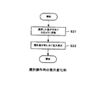
図3のフローチャートは、このシャッタ速度や絞りを選択する際の、表示の変化処理の例を示したフローチャートである。選択操作があると、そのときに選択される値が、画面の中央になるような表示となるように、値の表示を仮想設定される円に沿って回転させる(ステップS21)。そして、画面の中央の現在の設定値を拡大表示させる(ステップS22)。
【0035】
図9は、このように選択操作を行った場合の例を示した図である。ここでは、シャッタ速度として、図8に示した1/160秒から1/500秒に変化させた場合の例である。このように変化させることで、画面の中央の現在の設定値の表示131が、500と表示されるようになる。この場合、仮想設定される円に沿って表示されるその他の設定可能な値の配置順序は変わらず、設定されるシャッタ速度値よりも高速に設定できるシャッタ速度値の表示132で表示される値は少なくなる。逆に、設定されるシャッタ速度値よりも低速に設定できるシャッタ速度値の表示133,134として表示される値は増える。
【0036】
図9の例では、この表示される値が増えることで、仮想設定される円の後方の180°の範囲にも値を配置するようにした場合の例を示してあり、その後方での表示134については、文字を反転させて、後方であることが容易に判るようにしてある。
【0037】
そして、シャッタ速度を変えることで、設定される絞り値についても変化し、図9の例ではF2.5に変化したとする。このとき、画面の中央の現在の設定値の表示135が、F2.5と表示されるようになり、開放側に設定できる絞り値の表示136で表示される値は少なくなる。逆に、設定される絞り値よりも絞る側に設定できる絞り値の表示137,138として表示される値は増え、後端部の表示138については、文字を反転させて、後方であることが容易に判るようにしてある。
【0038】
このようにして選択操作が終わった後には、図4から図8への表示変化とは逆の表示移行処理を行って、再び図4に示したような表示形態に戻す処理が実行される。
【0039】
なお、ここではシャッタ速度をユーザ操作で変化させた例としたが、絞り値の方をユーザ操作で変化させる場合にも同様に表示を変化させることができる。
【0040】
以上説明したように操作時の表示が行われることで、中央での表示から選択された値が判るだけでなく、その選択された値以外の値についても、各値の配置状態から容易に判断できるようになる。また、選択された値が、選択できる範囲内のどの辺りであるかの見当をつけることも容易にできるようになる。さらに、仮想設定される円の後方に表示される文字や数字についても、反転させて表示させるようにしたことで、例えば選択可能な値の中の最も高速のシャッタ値を選択した場合であっても、低速側で選択可能なシャッタ値を全て表示から判断できるようになる。このように本例の表示処理を行うことで、物理的なダイヤル釦上にシャッタ値や絞り値を印刷させる等して表示させた場合とほぼ同様の表示形態となり、非常に判りやすい表示形態となる。
【0041】
また、選択操作をしない場合には、図4に示したように、現在設定されている値だけを画面中に小さく表示するだけであるので、通常の撮影時には、数字や文字などの表示で、撮影される画像を邪魔することがない。
【0042】
なお、図4〜図9に示した表示例では、画面上に仮想設定される円を、値が縦方向に並ぶような配置としたが、値が横方向に並ぶような配置の円としても良い。例えば図10に示すように、設定されるシャッタ速度値の表示141と、設定される絞り値の表示144とを、画面のほぼ中央に表示させ、その前後の値の表示142,143,145,146を、横方向に延びた楕円上にほぼ等間隔で配置させても良い。この図10の例では、画面上に仮想設定される円は、360°全てが画面上に入るようにはしてなく、一部の範囲だけが表示されるようにしてある。
【0043】
また、仮想設定される円として、その円で構成される平面が、表示パネルの表示面と所定の角度を持った立体的な円となるようにしたが、表示パネルの表示面と同じ平面に仮想設定される円に、文字や数字を配置しても良い。図11はこの場合の表示例を示した図であり、設定されるシャッタ速度値の表示151と、設定される絞り値の表示154とを、画面のほぼ中央に表示させ、その前後の値の表示152,153,155,156を、ほぼ一定の角度の間隔で行うようにしてある。この図11に示した例の場合には、現在の設定値以外の値の表示については、文字や数字のサイズが同じになる。
【0044】
なお、ここまでの説明では、シャッタ速度と絞り値を選択する場合の例について説明したが、その他の複数段階に調節可能な値を選択する場合の処理にも適用可能である。また、表示形態や表示される値についても、上述した各図では一例を示したものであり、その他の表示形態であっても良い。例えば、上述した例では、現在設定される値については、拡大表示するようにしたが、他の表示と区別できる態様で表示させれば、その他の表示態様であっても良く、例えば現在設定される値については、他の値と表示色を変えるようにしても良い。
【0045】
また、ここまで説明した例では、表示形態として円を仮想設定して、その円に沿って値などを配置するようにしたが、楕円を仮想設定して、その楕円に沿って値などを配置するようにしても良い。
【0046】
次に、本発明の第2の実施の形態を、図12〜図16を参照して説明する。
【0047】
本例においても、デジタルカメラと称される、静止画像又は動画像の撮影(撮像)を行って、得られた撮像データを半導体メモリなどの記憶手段(又は記録手段)に記憶させる電子機器に適用した例としてあり、撮影した映像を、液晶表示パネルなどで構成される表示手段に表示させて、その表示パネルに表示される映像を確認しながら撮影ができる構成としてある。
【0048】
デジタルカメラ全体の構成については、例えば、上述した第1の実施の形態で説明した図1と同じ構成が適用可能である。本例では、制御部18の制御に基づいて表示手段19で表示されるメニュー画面を、図12に示す表示例のように行うようにしたものであり、操作手段20の操作に基づいて、操作時の表示が行われる。
【0049】
図12の表示例について説明すると、この例では、例えば図12Aに示すように、設定項目表示210と、その表示210で選択された項目について選択可能な数値表示230とを、それぞれ画面中に、画面の表示面と所定の角度を持って仮想設定される円の一部の範囲だけを使用して行うようにしたものである。即ち、設定項目表示210として、画面上に仮想設定される円(楕円)上の一部の範囲だけを使用して、均等な角度範囲毎に、それぞれの設定項目を示す文字又は図形(アイコン)を表示させてある。図12Aでは、撮影感度を示す文字である「ISO」とある表示211が、選択される位置である正面に表示された状態を示してある。この例では、正面の表示211だけが、仮想設定される円から若干手前に飛び出した状態で、比較的大きな文字で設定項目「ISO」と表示させてあり、円上のその他の表示については、仮想設定される円上に、設定項目をアイコン化した比較的小さな図形で表示させてある。また、この選択された「ISO」を、3次元的なアイコンで示された図形による表示221を、設定項目表示210で形成される円の中心の若干上側に表示させてある。この立体表示221は、3次元ポリゴンモデルで表示させてある。
【0050】
そして、設定項目表示210で選択された設定項目(ここでは「ISO」)について、選択できる値についての数値表示230が、画面上に仮想設定される円(楕円)上の一部の範囲だけを使用して、均等な角度範囲毎に、それぞれの数値を示す数字を表示させてある。ここでは、正面の位置の表示231で示された数値「200」が、そのときに設定されている撮影感度を示してあり、選択できる他の値又は項目である、「400」,「100」,「オート」が、「200」の表示231の前後の円上に一定角度間隔で配置してある。この例では、選択された数値「200」については、他の位置の数値などの表示と区別できる態様で表示させてある。この例では表示色を変えて、区別してあるが、文字サイズなどの他の表示態様を変化させても良い。
【0051】
これらの設定項目表示210及び数値表示230は、上述した第1の実施の形態で説明した表示例の場合と同様に、設定項目表示210での各項目の配置順、及び数値表示230での各数値(又は文字)の配置順は、どの表示状態でも同じようにして、正面の位置に表示されるものが選択されるようにしてある。そして、仮想設定される円の後方の180°の範囲にも、値や項目などを表示させる必要がある場合には、上述した第1の実施の形態で説明した表示例の場合と同様に、数字や文字や図形を反対向きに反転させて表示させるようにしてある。
【0052】
なお、この図12Aの表示では、設定項目表示210を、画面中に水平方向に配置された円(楕円)として示してあり、数値表示230を、画面中に垂直方向に配置された円(楕円)として示してあり、設定項目表示210で仮想設定される円と、数値表示230で仮想設定される円とが、ほぼ直交する状態で示してある。
【0053】
このような表示形態の場合、操作手段20として、例えば上下左右の4方向を個別に指示できる4つのキーを使用して、例えば左キー又は右キーの操作で、設定項目表示210の正面の位置の表示項目を左又は右に順に変化させ、上キー又は下キーの操作で、数値表示230で表示された数値の正面の位置になる数値(又は文字)を上又は下に順に変化させるような操作と表示との連動が可能になる。
【0054】
或いは、左キーのような一方の方向への操作を行うキーと、右キーのような他方の方向への操作を行うキーと、確定操作を行うキーの3つのキーを使用して、最初に2つの方向のキーの操作に基づいて、設定項目表示210で項目を選ばせて、その後、確定操作後には、同じ2つの方向を指示するキーを使用して、数値表示230で表示された数値を選択するようにしても良い。また、このような複数のキーを使用した選択ではなく、いわゆるジョグダイヤルと称される回転型の操作手段を使用して、同様の入力操作を行うようにしても良い。
【0055】
そして、この図12Aに示す表示形態で、設定項目表示210の中の別の項目が選ばれると、数値表示230は、別の項目(そのとき正面にある項目)についての数値表示に変化する。但し、正面にある項目が、数値以外の状態を選ぶ項目である場合には、数値表示は、数値以外の項目などを示した表示になる。
【0056】
図12Bは、設定項目表示210を、図12Aに示す表示211が正面になった状態から、右方向に1つ隣の表示212を正面になるように変化させた場合の例である。但し、図12Bの表示状態は、表示212が完全には正面になってなく、図12Cに示す状態で表示212が正面になっている。正面でない状態では、表示212は、アイコン化された図形で表示させてあるが、その位置が完全に正面になることで、図12Cに示すように、文字により「画面サイズ」と表示されるようになる。また、正面から横に位置が変化した「ISO」の表示211については、文字からアイコン化された図形に表示が変化している。
【0057】
この例で正面になった表示212は、画面サイズを示す図形(アイコン)である。このように設定項目表示210を変化させた場合には、変化させた直後には、図12Bに示すように、数値表示として、そのときの画面サイズの数値(ここでは「1280×960」)の表示241だけが表示された状態になる。
【0058】
この図12Bに示す状態から、図12C,図12Dに示すように、画面サイズの数値の表示241の上下に、他の画面サイズの数値の表示240′,240″が徐々に広がっていき、最終的に選択可能な全ての画面サイズの数値が上下に環状に並んだ、図12Eに示す数値表示240となる。
【0059】
さらに本例においては、この数値表示240の広がりに連続して、画面サイズを示す立体的なアイコン表示222a,222bが、図12D,図12Eに示すように、設定項目表示210で形成される円の中心から若干上になるった位置に、徐々に広がって表示されるようにしてある。
【0060】
なお、図12に示したメニュー画面の表示は、このデジタルカメラで撮影中(又は撮影済)の画像に重畳させて表示させてあるが、例えば背景を単色に塗られた画像として、メニュー画面だけを表示させるようにしても良い。
【0061】
この図12に示すような表示形態による表示を行う際の、制御部18による表示制御処理の例を、図13のフローチャートに示す。ここでは、設定項目表示210による表示を第1階層表示とし、その設定項目表示の中で選択された項目についての数値表示を第2階層表示として示してある。以下、図13に基づいて説明すると、本例の表示を行うモード(即ちデジタルカメラのメニュー画面を表示させるモード)になると、第1階層を表示させるための処理(ステップS31)と、第2階層を表示させるための処理(ステップS32)と、3Dアイコン(図12D,Eでの表示222a,222b)を表示させるための処理(ステップS33)とが、そのときの設定状態に応じた態様で行われる。
【0062】
その後、設定変更に関係した何らかのキー入力があると(ステップS34)、第1階層の項目を変更させるキー入力か否か判断し(ステップS35)、該当するキー入力である場合に、第1階層の表示である設定項目表示210を回転させ(ステップS36)、第2階層表示を、そのときに正面の位置に表示される項目についての数値表示に切替えさせる(ステップS37)。さらに、そのときに正面の位置に表示される項目についての3Dアイコン表示を行う(ステップS38)。なお、第1階層の表示である設定項目表示210については、正面の表示項目だけを、アイコン化された図形表示から文字の表示に切替えさせてある。
【0063】
その後、制御部18は、メニュー画面の表示を終了させる操作があるか否か判断し(ステップS41)、該当する操作がある場合に、メニュー画面の表示を終了させる。メニュー画面の表示を終了させる操作がない場合には、ステップS34のキー入力があるまで待機する。
【0064】
そして、ステップS35で、第1階層を変更させる入力でないと判断した場合には、第2階層の表示を変更させるキー入力であるか否か判断し(ステップS39)、第2階層の表示を変更させるキー入力であると判断した場合に、第2階層の表示を回転させて、制御部18は、そのとき正面になる位置に表示される数値や文字で示される状態に、該当する項目を設定させるモード設定処理を行う(ステップS40)。その後、ステップS41の判断に移る。また、ステップS39で第2階層の表示を変更させるキー入力でないと判断した場合にも、ステップS41の判断に移る。
【0065】
このようにして表示制御処理が行われることで、2つの階層での円形表示(但し円は環状にはつながってない)に基づいて、調整可能な項目と、各項目毎の調整値などが、判り易いメニュー画面が表示されることになり、結果的にデジタルカメラなどの適用した機器の操作性が向上する。特に本例のように、2つの階層で表示される円が、図12に示すようにほぼ直交した状態で表示されるので、調整項目と、それぞれの項目毎の数値などとの対応が判り易く、1画面内で多項目のメニュー選択が良好に行える表示形態となる。
【0066】
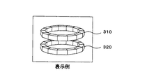
なお、図12に示した例では、第1階層の表示210と、第2階層の表示230とが、それぞれの表示で画面中に仮想的に形成される円どうしが直交するような配置としたが、それぞれの階層で画面中に形成される円が、並ぶようにしても良い。例えば図14に示すように、第1階層の円表示310と、第2階層の円表示320とが、上下に並ぶような表示形態としても良い。また、例えば図15に示すように、第1階層の円表示410と、第2階層の円表示420とが、左右に並ぶような表示形態としても良い。但し、図13,図14の例では、説明を簡単にするために、それぞれの円表示を環状につなげて示してあるが、図12などの例のように、その円の中の一部の領域だけにアイコンや数値を配置させるようにしても良い。或いは、一方の階層(例えば第1階層)については、図13,図14に示したような環状につなげた円表示であっても良く、さらには2つの階層が環状につなげた円表示であっても良い。
【0067】
また、図16に示すように、第1階層の円表示510と、第2階層の円表示520と、第3階層の円表示530とを同時に行うようにしても良い。この場合、図16では3つの階層が左右に並んでいるが、例えば第1階層の円表示510については、他の2つの階層の円表示520,530とは直交する水平方向の円として表示させても良い。この図16の表示例の場合にも、説明を簡単にするために、それぞれの円表示を環状につなげて示してあるが、図12などの例のように、その円の中の一部の領域だけにアイコンや数値を配置させるようにしても良い。
【0068】
なお、ここまでの説明では、本発明の処理が適用される機器として、静止画像又は動画像が撮影(撮像)できる電子機器であるデジタルカメラを例にして説明したが、同様なメニュー画面の表示が可能な表示手段を備えた機器であれば、デジタルカメラ以外の各種電子機器にも適用可能であることは勿論である。
【0069】
【発明の効果】
第1の発明によると、選択できる状態の値又は項目が、仮想設定される円または楕円の一部の範囲に配置されて表示され、所定位置での表示から選択された値や項目が判るだけでなく、例えば、値が表示される場合には、その選択された値以外の値についても、各値の配置状態から容易に判断できるようになる。また、選択された値が、選択できる範囲内のどの辺りであるかの見当をつけることも容易にできるようになる。
【0070】
この場合、表示パネル上に仮想設定される円または楕円は、表示パネルの表示面と所定の角度を持って立体的に仮想設定される円または楕円であり、その仮想設定される円または楕円に沿って配置される値は、円の弧に沿って傾斜した文字又は数字で表示させることで、選択された値又は項目と、その他の値又は項目とが立体的に表示されるようになり、判りやすい良好な表示形態となる。
【0071】
また、選択された値又は項目以外の値又は項目の内の、仮想設定される円または楕円の後方に配置される値又は項目については、反転した文字又は数字で表示させることで、その位置に配置される値や項目についても表示から容易に判断できるようになる。
【0072】
また、値や項目の選択を行うモードを設定した場合に、表示パネル上に選択されている値又は項目だけが表示された状態から、仮想設定される円または楕円に沿って、そのとき選択されている値又は項目以外の値又は項目の表示が広がって、所定の順序の配置で表示される状態に変化するようにしたことで、選択を行うモードになっているか否かが、表示パネルでの表示から容易に判断できるようになる。
【0073】
また、選択された値や項目を、他の値や項目よりも大きな文字又は数字で表示させて、区別できる態様で表示させることで、より判りやすい表示形態となる。
【0074】
第2の発明によると、複数の階層毎に、文字,数字,アイコンなどで、仮想設定される円または楕円の一部の範囲に配置されて表示され、それぞれの階層毎の所定位置での表示から選択された値や項目が判るようになり、例えば調整可能な項目と、各項目毎の調整値などが判りやすく同時に表示されるようになり、非常に判りやすいメニュー画面が表示できる。
【0075】
この場合、表示パネル上に仮想設定されるそれぞれの円または楕円は、表示パネルの表示面と所定の角度を持って立体的に仮想設定される円または楕円であり、その仮想設定される円または楕円に沿って配置される値は、円の弧に沿って傾斜した文字又は数字で表示させることで、選択された値又は項目と、その他の値又は項目とが立体的に表示されるようになり、判りやすい良好な表示形態となる。
【0076】
また、それぞれの円又は楕円に沿って表示される、選択された値又は項目以外の値又は項目の内の、仮想設定される円または楕円の後方に配置される値又は項目については、反転した文字又は数字で表示させることで、その位置に配置される値や項目についても表示から容易に判断できるようになる。
【0077】
また、値や項目の選択を行うモードを設定した場合に、表示パネル上に選択されているそれぞれの値又は項目だけが表示された状態から、仮想設定される円または楕円に沿って、そのとき選択されている値又は項目以外の値又は項目の表示が広がって、所定の順序の配置で表示される状態に変化するようにしたことで、選択を行うモードになっているか否かが、表示パネルでの表示から容易に判断できるようになる。
【0078】
また、選択された値や項目を、他の値や項目と区別できる態様で表示させることで、より判りやすい表示形態となる。
【0079】
また、第1の円または楕円に沿って配置される項目の中から選択した項目について選択できる値を、第2の円または楕円に沿って配置することで、2つの円又は楕円に沿って表示される項目や数値が相互に関連した判りやすい表示形態となる。
【0080】
また、第1又は第2の円または楕円に沿って配置される項目の中から選択した項目を示す図形又は文字を、表示パネル上の第1及び第2の円または楕円に沿った位置とは異なる位置に表示させることで、より選択された項目が判り易くなる。
【図面の簡単な説明】
【図1】本発明の第1の実施の形態によるデジタルカメラの構成例を示すブロック図である。
【図2】本発明の第1の実施の形態による操作時の表示変化例を示したフローチャートである。
【図3】本発明の第1の実施の形態による選択操作時の表示変化例を示したフローチャートである。
【図4】本発明の第1の実施の形態による表示例(通常モードの例)を示した説明図である。
【図5】本発明の第1の実施の形態による表示例(操作モードへの移行途中例)を示した説明図である。
【図6】本発明の第1の実施の形態による表示例(操作モードへの移行途中例)を示した説明図である。
【図7】本発明の第1の実施の形態による表示例(操作モードへの移行途中例)を示した説明図である。
【図8】本発明の第1の実施の形態による表示例(操作モード時の例)を示した説明図である。
【図9】本発明の第1の実施の形態による表示例(設定を変えた場合の例)を示した説明図である。
【図10】本発明の第1の実施の形態による表示の変形例を示した説明図である。
【図11】本発明の第1の実施の形態による表示の更に別の変形例を示した説明図である。
【図12】本発明の第2の実施の形態による表示例を示した説明図である。
【図13】本発明の第2の実施の形態による表示処理を示したフローチャートである。
【図14】本発明の第2の実施の形態による表示の変形例を示した説明図である。
【図15】本発明の第2の実施の形態による表示の更に別の変形例を示した説明図である。
【図16】本発明の第2の実施の形態による表示の更に別の変形例を示した説明図である。
【符号の説明】
11…レンズ、12…アイリス、13…撮像素子、14…撮像処理部、15…画像処理部、16…内蔵メモリ、17…メモリカード、18…制御部、19…表示手段、20…操作手段[0001]
TECHNICAL FIELD OF THE INVENTION
The present invention relates to a display method and a display device for displaying a set value of an electronic device when there are a plurality of set values, such as a set value of a shutter speed and an aperture in a digital camera, for example.
[0002]
[Prior art]
2. Description of the Related Art Conventionally, in a device such as a digital camera or a video camera having a display panel for displaying a captured (captured) video, the display panel can superimpose the captured video and display various setting states. Has been done.
[0003]
For example, in the case of a digital camera that records a photographed image as digital data on a memory card having a built-in semiconductor memory, there is a type that displays a shutter speed value at the time of photographing, an aperture value, and the like. There are cases where these values can be set freely by user operation and cases where they are automatically set by the camera. In any case, the setting status according to the shooting situation at that time is displayed. By displaying the information on the panel, it is convenient for the person who performs the shooting operation to be notified.
[0004]
In addition, some setting states such as a shooting mode are simultaneously displayed on the display panel.
[0005]
[0006]
[Patent Document 1]
JP-A-2002-163103
[0007]
[Problems to be solved by the invention]
By the way, when there are a plurality of values and modes that can be set, if only the currently set values and modes are displayed on the display panel, it is not easy to understand what other values and modes can be set. There's a problem. For this reason, it is conceivable that not only the currently set value and mode but also other settable values and mode are simultaneously displayed on the display panel.
[0008]
In the case of the processing described in
[0009]
In particular, as for the values that need to be changed at any time during photographing, such as the shutter speed value and the aperture value in the case of the digital camera described above, it is better to easily find other values that can be set. For this reason, instead of the annular mode display described in
[0010]
In addition, as for the setting state such as the shutter speed value and the aperture value, it is preferable that it is easy to see from the display which area is selected in the selectable range, but in the conventional display mode, I didn't know that. For example, when a display area is prepared in a ring shape as described in
[0011]
SUMMARY OF THE INVENTION It is an object of the present invention to provide an electronic apparatus such as a digital camera capable of displaying a setting state and the like satisfactorily.
[0012]
[Means for Solving the Problems]
According to the present invention, when displaying a setting state of an electronic device, values or items of a state that can be selected in a plurality of stages are displayed in a predetermined order along a partial range of a circle or an ellipse virtually set on a display panel. With the arrangement and the predetermined order maintained, the selected value or item is displayed at a predetermined position of a virtually set circle or ellipse, and for the selected value or item, other values are displayed. It is displayed in a manner that can be distinguished from the value or the item.
[0013]
By doing so, the values or items in a selectable state are arranged and displayed in a part of the virtually set circle or ellipse, and the value or item selected from the display at a predetermined position can be determined. Not only that, the value or item other than the selected value or item can be easily determined from the arrangement state of each value or item. Further, it is possible to easily determine the approximate range of the selected value or item within the selectable range.
[0014]
BEST MODE FOR CARRYING OUT THE INVENTION
Hereinafter, a first embodiment of the present invention will be described with reference to FIGS.
[0015]
In this example, the present invention is applied to an electronic apparatus called a digital camera that captures (takes) a still image or a moving image and stores the obtained image data in a storage unit (or a recording unit) such as a semiconductor memory. Here is an example. The digital camera according to the present embodiment is configured so that a captured image is displayed on a display unit including a liquid crystal display panel or the like, and the image can be captured while checking the image displayed on the display panel.
[0016]
FIG. 1 is a diagram illustrating an example of the overall configuration of a digital camera. Image light formed on an imaging surface of an
[0017]
The aperture value and the shutter speed may be set freely by a user's operation, or may be automatically set according to the shooting conditions at that time. However, since the aperture value and the shutter speed are values that are interrelated at the time of photographing, it is general that when one of them is set by a user operation, the other is automatically set to an appropriate value.
[0018]
The
[0019]
The display image signal processed by the
[0020]
The imaging by the
[0021]
When photographing is performed with the digital camera of this embodiment configured as described above, a setting state related to photographing is displayed in characters, numerals, figures, and the like on a display panel constituting the
[0022]
In the following, display processing on the display panel in the digital camera of the present example will be described. During normal shooting, for example, a display as shown in FIG. 4 is performed. That is, in a state in which the captured image is displayed on the background and the image is superimposed on the image, the shutter
[0023]
In this state, when a mode for selecting a shutter speed value or an aperture value is selected by operating the
[0024]
FIG. 5 to FIG. 8 are diagrams showing examples of the display transition processing state of steps S11 to S13. First, from the state where the shutter
[0025]
With the shutter
[0026]
Similarly, as shown in FIG. 6, the
[0027]
When the shutter speed value and aperture value that can be set other than the value currently being set are displayed in a wide range, these values should be spread along the arc of a circle that is virtually set three-dimensionally on the screen. is there. The circle that is virtually set three-dimensionally on this screen is a circle that is arranged on a plane having a predetermined angle with the display surface of the display panel, but the display surface and the circle of the display panel are arranged. The angle between the plane and the plane is slightly smaller than 90 ° which is an orthogonal angle.
[0028]
FIG. 7 is a diagram showing an example of a state in which a shutter speed value and an aperture value that can be set to values other than the value currently being set are further displayed from the state shown in FIG. A
[0029]
Similarly, as shown in FIG. 7, an aperture value display 125 'that can be set to an open side from the aperture value currently being set is displayed so as to extend upward from the current
[0030]
FIG. 8 shows an example of a completely spread state. A shutter
[0031]
Similarly, as shown in FIG. 8, the
[0032]
In this example, finally, as shown in FIG. 8, the
[0033]
In this way, there is a display transition in the operation mode shown in the flowchart of FIG. 2, and the display as shown in FIG. 8 allows the shutter speed and aperture to be selected by the user operation. By operating a predetermined key or the like of the
[0034]
The flowchart of FIG. 3 is a flowchart showing an example of display change processing when selecting the shutter speed and aperture. When there is a selection operation, the display of the value is rotated along a circle that is virtually set so that the value selected at that time is displayed at the center of the screen (step S21). Then, the current set value at the center of the screen is enlarged and displayed (step S22).
[0035]
FIG. 9 is a diagram illustrating an example of a case where the selection operation is performed as described above. Here, an example is shown in which the shutter speed is changed from 1/160 second shown in FIG. 8 to 1/500 second. With this change, the
[0036]
In the example of FIG. 9, an example is shown in which the displayed value is increased so that the value is also arranged in a range of 180 ° behind the virtually set circle. With regard to 134, the characters are inverted so that it is easy to see that it is the back.
[0037]
By changing the shutter speed, the aperture value to be set also changes, and in the example of FIG. 9, it is assumed that the aperture value has changed to F2.5. At this time, the display 135 of the current set value in the center of the screen is displayed as F2.5, and the value displayed on the
[0038]
After the selection operation is completed in this manner, a display transition process reverse to the display change from FIG. 4 to FIG. 8 is performed, and a process of returning to the display form as shown in FIG. 4 is executed again.
[0039]
Here, an example in which the shutter speed is changed by a user operation is described, but the display can be similarly changed when the aperture value is changed by a user operation.
[0040]
As described above, the display at the time of the operation is performed, so that not only the value selected from the display at the center can be known but also the value other than the selected value can be easily determined from the arrangement state of each value. become able to. In addition, it is possible to easily determine the approximate range of the selected value within the selectable range. Furthermore, characters and numbers displayed behind the circle to be virtually set are also displayed in an inverted manner, for example, when the fastest shutter value among the selectable values is selected. Also, all the shutter values that can be selected on the low speed side can be determined from the display. As described above, by performing the display processing of this example, the display form becomes almost the same as the case where the shutter value and the aperture value are printed on the physical dial button and displayed, and the display form is very easy to understand. Become.
[0041]
When no selection operation is performed, as shown in FIG. 4, only the currently set value is merely displayed in a small size on the screen. Therefore, during normal shooting, numerals and characters are displayed. It does not disturb the captured image.
[0042]
In the display examples shown in FIGS. 4 to 9, the circles virtually set on the screen are arranged such that the values are arranged vertically, but may be arranged as circles in which the values are arranged horizontally. good. For example, as shown in FIG. 10, a
[0043]
In addition, as the circle to be virtually set, the plane formed by the circle is a three-dimensional circle having a predetermined angle with the display surface of the display panel, but the same plane as the display surface of the display panel is used. Characters and numbers may be arranged in a circle that is virtually set. FIG. 11 is a diagram showing a display example in this case, in which a
[0044]
In the above description, an example in which the shutter speed and the aperture value are selected has been described. However, the present invention is also applicable to a process in which other values that can be adjusted in a plurality of stages are selected. Also, the display modes and displayed values are only examples in the above-described drawings, and other display modes may be used. For example, in the above-described example, the currently set value is displayed in an enlarged manner. However, if the value is displayed in a form that can be distinguished from other displays, other display forms may be used. As for the value, the display color may be changed from other values.
[0045]
In the example described so far, a circle is virtually set as a display form and values and the like are arranged along the circle. However, an ellipse is virtually set and values and the like are arranged along the ellipse. You may do it.
[0046]
Next, a second embodiment of the present invention will be described with reference to FIGS.
[0047]
Also in this example, the present invention is applied to an electronic device called a digital camera that captures (takes an image of) a still image or a moving image and stores the obtained image data in a storage unit (or a recording unit) such as a semiconductor memory. In this example, the captured video is displayed on a display unit including a liquid crystal display panel or the like, and the user can shoot while checking the video displayed on the display panel.
[0048]
For the configuration of the entire digital camera, for example, the same configuration as that of FIG. 1 described in the first embodiment can be applied. In this example, the menu screen displayed on the
[0049]
The display example of FIG. 12 will be described. In this example, as shown in FIG. 12A, for example, a
[0050]
Then, for the setting item selected in the setting item display 210 (here, “ISO”), the
[0051]
The setting
[0052]
In the display of FIG. 12A, the setting
[0053]
In the case of such a display mode, for example, four keys that can individually indicate four directions, up, down, left, and right, are used as the
[0054]
Alternatively, three keys such as a key for performing an operation in one direction such as a left key, a key for performing an operation in the other direction such as a right key, and a key for performing a confirming operation are used first. The user selects an item in the
[0055]
Then, when another item in the
[0056]
FIG. 12B is an example in which the
[0057]
The
[0058]
From the state shown in FIG. 12B, as shown in FIGS. 12C and 12D,
[0059]
Further, in the present example, three-
[0060]
The display of the menu screen shown in FIG. 12 is displayed so as to be superimposed on an image being photographed (or photographed) by the digital camera. May be displayed.
[0061]
An example of display control processing by the
[0062]
Thereafter, if there is any key input related to the setting change (step S34), it is determined whether or not the key input changes the item of the first hierarchy (step S35). Is rotated (step S36), and the second hierarchical display is switched to a numerical display for the item displayed at the front position at that time (step S37). Further, a 3D icon is displayed for the item displayed at the front position at that time (step S38). In the
[0063]
Thereafter, the
[0064]
If it is determined in step S35 that the input is not an input for changing the first hierarchy, it is determined whether the input is a key input for changing the display of the second hierarchy (step S39), and the display of the second hierarchy is changed. If it is determined that the input is a key input to turn on, the display of the second hierarchy is rotated, and the
[0065]
By performing the display control process in this manner, based on the circular display at two levels (however, the circles are not connected in a ring), the adjustable items and the adjustment value for each item are displayed. An easy-to-understand menu screen is displayed, and as a result, the operability of a device such as a digital camera is improved. Particularly, as shown in this example, circles displayed in two layers are displayed in a substantially orthogonal state as shown in FIG. 12, so that it is easy to understand the correspondence between adjustment items and numerical values of each item. (1) A display mode in which menu selection of many items can be favorably performed in one screen.
[0066]
In the example shown in FIG. 12, the
[0067]
Further, as shown in FIG. 16, a
[0068]
In the above description, a digital camera, which is an electronic device capable of capturing (capturing) a still image or a moving image, has been described as an example of the device to which the processing of the present invention is applied. It is needless to say that the present invention can be applied to various electronic devices other than the digital camera as long as the device has a display means capable of performing the above operations.
[0069]
【The invention's effect】
According to the first invention, the values or items in a selectable state are arranged and displayed in a part of a circle or an ellipse to be virtually set, and only the selected values or items are known from the display at a predetermined position. Instead, for example, when a value is displayed, a value other than the selected value can be easily determined from the arrangement state of each value. In addition, it is possible to easily determine the approximate range of the selected value within the selectable range.
[0070]
In this case, the circle or ellipse virtually set on the display panel is a circle or ellipse set three-dimensionally at a predetermined angle with the display surface of the display panel. By displaying the values arranged along with letters or numbers inclined along the arc of the circle, the selected value or item and other values or items will be displayed three-dimensionally, A good display form that is easy to understand is obtained.
[0071]
In addition, among the values or items other than the selected value or item, the values or items arranged behind the virtually set circle or ellipse are displayed in inverted characters or numbers, so that The values and items to be arranged can be easily determined from the display.
[0072]
When a mode for selecting a value or an item is set, only the value or the item selected on the display panel is displayed, and the selected value or the item is selected along the virtually set circle or ellipse at that time. The display of the value or item other than the value or item that is displayed is expanded and changed to the state of being displayed in the predetermined order, so that whether or not the mode for selecting is on the display panel. Can be easily determined based on the display of.
[0073]
In addition, the selected value or item is displayed in a character or number that is larger than other values or items, and is displayed in a distinguishable manner, so that the display form can be more easily understood.
[0074]
According to the second invention, characters, numerals, icons, and the like are arranged and displayed in a part of a virtually set circle or ellipse for each of a plurality of layers, and are displayed at predetermined positions for each of the layers. For example, an adjustable item and an adjustment value for each item are displayed simultaneously in an easy-to-understand manner, and a very easy-to-understand menu screen can be displayed.
[0075]
In this case, each circle or ellipse virtually set on the display panel is a circle or ellipse that is virtually set three-dimensionally at a predetermined angle with the display surface of the display panel, and the virtually set circle or ellipse is Values arranged along the ellipse are displayed as letters or numbers inclined along the arc of the circle, so that the selected value or item and other values or items are displayed three-dimensionally. And a good display form that is easy to understand.
[0076]
In addition, among values or items other than the selected value or item displayed along each circle or ellipse, values or items arranged behind the virtually set circle or ellipse are inverted. By displaying characters or numbers, it is possible to easily determine the values and items arranged at the positions from the display.
[0077]
When a mode for selecting a value or an item is set, only the selected value or item on the display panel is displayed, and then, along a circle or an ellipse virtually set, The display of the value or item other than the selected value or item is expanded and changed to the state of being displayed in the predetermined order, so that whether or not the mode for selecting is displayed It can be easily determined from the display on the panel.
[0078]
In addition, by displaying the selected value or item in a form that can be distinguished from other values or items, a more easily understandable display mode is provided.
[0079]
In addition, a value that can be selected for an item selected from items arranged along the first circle or ellipse is displayed along the two circles or ellipse by arranging the value along the second circle or ellipse. The displayed items and numerical values are related to each other and are easy to understand.
[0080]
Also, a figure or a character indicating an item selected from items arranged along the first or second circle or ellipse is defined as a position on the display panel along the first and second circles or ellipse. By displaying the selected item at a different position, the selected item becomes easier to understand.
[Brief description of the drawings]
FIG. 1 is a block diagram illustrating a configuration example of a digital camera according to a first embodiment of the present invention.
FIG. 2 is a flowchart showing an example of a display change at the time of an operation according to the first embodiment of the present invention.
FIG. 3 is a flowchart showing a display change example at the time of a selection operation according to the first embodiment of the present invention.
FIG. 4 is an explanatory diagram showing a display example (an example of a normal mode) according to the first embodiment of the present invention.
FIG. 5 is an explanatory diagram showing a display example (an example of a transition to an operation mode) according to the first embodiment of the present invention.
FIG. 6 is an explanatory diagram showing a display example (an example of a transition to an operation mode) according to the first embodiment of the present invention.
FIG. 7 is an explanatory diagram showing a display example (an example of a transition to an operation mode) according to the first embodiment of the present invention.
FIG. 8 is an explanatory diagram showing a display example (an example in an operation mode) according to the first embodiment of the present invention.
FIG. 9 is an explanatory diagram showing a display example (an example in a case where settings are changed) according to the first embodiment of the present invention.
FIG. 10 is an explanatory diagram showing a modification of the display according to the first embodiment of the present invention.
FIG. 11 is an explanatory diagram showing still another modification of the display according to the first embodiment of the present invention.
FIG. 12 is an explanatory diagram showing a display example according to the second embodiment of the present invention.
FIG. 13 is a flowchart illustrating a display process according to the second embodiment of the present invention.
FIG. 14 is an explanatory diagram showing a modification of the display according to the second embodiment of the present invention.
FIG. 15 is an explanatory diagram showing still another modified example of the display according to the second embodiment of the present invention.
FIG. 16 is an explanatory diagram showing still another modified example of the display according to the second embodiment of the present invention.
[Explanation of symbols]
DESCRIPTION OF
Claims (24)
複数段階に選択できる状態の値または項目を、表示パネル上に仮想設定される円、または楕円の一部の範囲に沿って所定の順序で配置し、
前記所定の順序を維持した状態で、その中の選択された値または項目を、前記仮想設定される円または楕円の所定位置に表示し、その選択された値または項目については、他の値または項目と区別できる態様で表示するようにした
表示方法。In a display method for displaying a setting state of an electronic device,
Place values or items in a state that can be selected in multiple stages, in a predetermined order along a part of a circle or an ellipse virtually set on the display panel,
While maintaining the predetermined order, the selected value or item is displayed at a predetermined position of the virtually set circle or ellipse, and for the selected value or item, another value or item is displayed. A display method that is displayed in a form that can be distinguished from items.
前記表示パネル上に仮想設定される円、または楕円は、前記表示パネルの表示面と所定の角度を持って立体的に仮想設定される円または楕円であり、その仮想設定される円または楕円に沿って配置される値または項目は、円の弧に沿って傾斜した文字又は数字で表示させる
表示方法。The display method according to claim 1,
The circle or the ellipse virtually set on the display panel is a circle or an ellipse that is virtually set three-dimensionally at a predetermined angle with the display surface of the display panel. A display method in which values or items arranged along are displayed by letters or numbers inclined along an arc of a circle.
前記選択された値以外の値または項目の内の、前記仮想設定される円、または楕円の後方に配置される値または項目については、反転した文字又は数字で表示させる
表示方法。The display method according to claim 2,
A display method in which, among values or items other than the selected value, values or items arranged behind the virtually set circle or ellipse are displayed in inverted characters or numbers.
前記値または項目の選択を行うモードを設定した場合に、前記表示パネル上に選択されている値または項目だけが表示された状態から、前記仮想設定される円または楕円に沿って、そのとき選択されている値または項目以外の値または項目が広がって、前記所定の順序の配置で表示される状態に変化するようにした
表示方法。The display method according to claim 1,
When the mode for selecting the value or the item is set, only the value or the item selected on the display panel is displayed, and then selected along the virtually set circle or ellipse. A display method in which a value or item other than the specified value or item spreads and changes to a state in which the value or item is displayed in the predetermined order.
選択された値または項目を、他の値または項目よりも大きな文字又は数字で表示させて、区別できる態様で表示させる
表示方法。The display method according to claim 1,
A display method in which a selected value or item is displayed in characters or numbers larger than other values or items, and displayed in a distinguishable manner.
複数段階に選択できる第1の状態の値または項目を、表示パネル上に仮想設定される第1の円または楕円の一部の範囲に沿って所定の順序で配置し、
前記所定の順序を維持した状態で、その中の選択された値または項目を、前記仮想設定される第1の円または楕円の所定位置に表示し、その選択された値または項目については、他の値または項目と区別できる態様で表示し、
さらに複数段階に選択できる第2の状態の値または項目を、表示パネル上に仮想設定される第2の円または楕円の一部の範囲に沿って所定の順序で配置し、
前記所定の順序を維持した状態で、その中の選択された値または項目を、前記仮想設定される第2の円または楕円の所定位置に表示し、その選択された値または項目については、他の値または項目と区別できる態様で表示するようにした
表示方法。In a display method for displaying a setting state of an electronic device,
A first state value or item that can be selected in a plurality of stages is arranged in a predetermined order along a partial range of a first circle or ellipse virtually set on the display panel,
In the state where the predetermined order is maintained, the selected value or item is displayed at a predetermined position of the first circle or ellipse that is virtually set. For the selected value or item, Is displayed in a manner that can be distinguished from the value or item of
Further, the values or items of the second state that can be selected in a plurality of stages are arranged in a predetermined order along a partial range of a second circle or ellipse virtually set on the display panel,
In the state where the predetermined order is maintained, the selected value or item is displayed at a predetermined position of the second circle or ellipse that is virtually set. A display method in which the value or the item is displayed in a manner that can be distinguished from the item.
前記表示パネル上に仮想設定される第1の円または楕円の一部の範囲に沿って配置される項目は、操作入力を行う項目であり、その第1の円の前記所定位置に表示された項目について選択できる数値を、第2の円または楕円の一部の範囲に沿って配置して表示させる
表示方法。The display method according to claim 6,
Items arranged along a partial range of the first circle or ellipse virtually set on the display panel are items for performing an operation input, and are displayed at the predetermined position of the first circle. A display method in which numerical values that can be selected for an item are arranged and displayed along a partial range of a second circle or ellipse.
前記表示パネル上に仮想設定される第1及び第2の円または楕円は、前記表示パネルの表示面と所定の角度を持って立体的に仮想設定される円または楕円であり、その仮想設定される第1及び第2の円または楕円に沿って配置される値または項目は、円の弧に沿って傾斜した文字又は数字で表示させる
表示方法。The display method according to claim 6,
The first and second circles or ellipses that are virtually set on the display panel are circles or ellipses that are virtually set three-dimensionally at a predetermined angle with respect to the display surface of the display panel. A display method in which values or items arranged along the first and second circles or ellipses are displayed as characters or numbers inclined along the arc of the circle.
前記選択された値以外の値または項目の内の、前記仮想設定される第1及び第2の円または楕円の後方に配置される値または項目については、反転した文字又は数字で表示させる
表示方法。The display method according to claim 8,
A display method in which, among values or items other than the selected value, values or items arranged behind the virtually set first and second circles or ellipses are displayed in inverted characters or numbers. .
選択された値または項目を、他の値または項目と区別できる態様で表示させる
表示方法。The display method according to claim 6,
A display method for displaying a selected value or item in a manner that can be distinguished from other values or items.
前記第1の円または楕円に沿って配置される項目の中から選択した項目について選択できる値を、前記第2の円または楕円に沿って配置する
表示方法。The display method according to claim 6,
A display method for arranging, along the second circle or ellipse, a value that can be selected for an item selected from the items arranged along the first circle or ellipse.
前記第1又は第2の円または楕円に沿って配置される項目の中から選択した項目を示す図形又は文字を、前記表示パネル上の前記第1及び第2の円または楕円に沿った位置とは異なる位置に表示させる
表示方法。The display method according to claim 6,
A figure or a character indicating an item selected from the items arranged along the first or second circle or ellipse is positioned on the display panel along the first and second circles or ellipse. Is a display method to display in different positions.
操作手段により設定された設定状態を表示する表示パネルと、
前記操作手段による操作入力に基づいて、複数段階に設定可能な値または項目の内のいずれかの値または項目を設定する制御を行うと共に、その設定の制御を行った場合に、前記複数段階に設定できる値または項目を、表示パネル上に仮想設定される円または楕円の一部の範囲に沿って所定の順序で配置し、前記所定の順序を維持した状態で、その中の前記操作手段の操作で設定された値または項目を、前記仮想設定される円または楕円の所定位置に表示し、その選択された値または項目については、他の値または項目と区別できる態様で表示する表示制御を行う制御手段とを備えた
表示装置。Operating means for performing operation input;
A display panel for displaying a setting state set by the operation means;
Based on the operation input by the operating means, while performing control to set any value or item of the values or items that can be set in a plurality of steps, when the control of the setting is performed, the plurality of steps The settable values or items are arranged in a predetermined order along a partial range of a circle or an ellipse virtually set on the display panel, and while the predetermined order is maintained, the operation means of the operation means therein is A display control for displaying a value or an item set by the operation at a predetermined position of the virtually set circle or ellipse, and displaying the selected value or item in a manner distinguishable from other values or items. A display device comprising:
前記制御手段の制御で、前記表示パネル上に仮想設定される円または楕円は、前記表示パネルの表示面と所定の角度を持って立体的に仮想設定される円または楕円であり、その仮想設定される円または楕円に沿って配置される値または項目は、円の弧に沿って傾斜した文字又は数字で表示させる
表示装置。The display device according to claim 13,
Under the control of the control means, the circle or the ellipse virtually set on the display panel is a circle or an ellipse that is virtually set three-dimensionally at a predetermined angle with respect to the display surface of the display panel. A display device for displaying values or items arranged along a circle or an ellipse to be displayed by letters or numbers inclined along the arc of the circle.
前記制御手段は、前記選択された値または項目以外の値または項目の内の、前記仮想設定される円または楕円の後方に配置される値または項目については、反転した文字又は数字で表示させる制御を行う
表示装置。The display device according to claim 14,
The control unit controls the value or item other than the selected value or item, which is arranged behind the virtually set circle or ellipse, to be displayed in inverted characters or numbers. Display device to do.
前記操作手段の操作で、前記値の選択を行うモードを設定した場合に、前記制御手段は、前記表示パネル上に選択されている値または項目だけが表示された状態から、前記仮想設定される円または楕円に沿って、そのとき選択されている値または項目以外の値または項目が広がって、前記所定の順序の配置で表示される状態に変化する表示制御を行う
表示装置。The display device according to claim 13,
When the mode for selecting the value is set by the operation of the operation unit, the control unit performs the virtual setting from a state in which only the selected value or item is displayed on the display panel. A display device that performs display control in which a value or item other than the value or item selected at that time spreads along a circle or an ellipse and changes to a state where the value or item is displayed in the predetermined order.
前記制御手段は、前記操作手段の操作で選択された値または項目を、他の値または項目よりも大きな文字又は数字で表示させて、区別できる態様で表示させる制御を行う
表示装置。The display device according to claim 13,
A display device that performs control to display a value or an item selected by an operation of the operation unit with a character or a number larger than other values or items and to display the selected value or item in a distinguishable manner.
操作手段により設定された設定状態を表示する表示パネルと、
前記操作手段による操作入力に基づいて、複数段階に設定可能な値または項目の内のいずれかの第1及び第2の値または項目を設定する制御を行うと共に、その第1及び第2の値または項目の設定の制御を行った場合に、前記複数段階に設定できる第1及び第2の値または項目を、表示パネル上に仮想設定される第1及び第2の円または楕円の一部の範囲に沿って所定の順序で配置し、前記所定の順序を維持した状態で、その中の前記操作手段の操作で設定された値または項目を、前記仮想設定される第1及び第2の円または楕円の所定位置に表示し、その選択された値または項目については、他の値または項目と区別できる態様で表示する表示制御を行う制御手段とを備えた
表示装置。Operating means for performing operation input;
A display panel for displaying a setting state set by the operation means;
Based on the operation input by the operation means, control is performed to set any one of the first and second values or items among the values or items that can be set in a plurality of stages, and the first and second values are set. Or, when the control of the setting of the item is performed, the first and second values or items that can be set in the plurality of stages are changed to a part of the first and second circles or ellipses virtually set on the display panel. Arranged in a predetermined order along the range, and in the state where the predetermined order is maintained, the values or items set by the operation of the operation means therein are replaced with the first and second circles virtually set. Or a control unit for performing display control for displaying the selected value or item in a predetermined position of the ellipse and displaying the selected value or item in a manner distinguishable from other values or items.
前記制御手段の制御で、前記表示パネル上に仮想設定される第1及び第2の円または楕円は、前記表示パネルの表示面と所定の角度を持って立体的に仮想設定される円または楕円であり、その仮想設定される第1及び第2の円または楕円に沿って配置される値または項目は、円の弧に沿って傾斜した文字又は数字で表示させる
表示装置。The display device according to claim 18,
Under the control of the control unit, the first and second circles or ellipses virtually set on the display panel are circles or ellipses set three-dimensionally virtually at a predetermined angle with the display surface of the display panel. And a value or item arranged along the first and second circles or the ellipse that is virtually set is displayed as characters or numbers inclined along the arc of the circle.
前記制御手段は、前記選択された値または項目以外の値または項目の内の、前記仮想設定される第1及び第2の円または楕円の後方に配置される値または項目については、反転した文字又は数字で表示させる制御を行う
表示装置。The display device according to claim 19,
The control means may include, for a value or an item other than the selected value or the item other than the selected value or the item, the value or the item disposed behind the first and second circles or the ellipse to be virtually set, an inverted character. Or, a display device that performs control for displaying numerically.
前記操作手段の操作で、前記第1または第2の値または項目の選択を行うモードを設定した場合に、前記制御手段は、前記表示パネル上に選択されている第1または第2の値または項目だけが表示された状態から、前記仮想設定される第1または第2の円または楕円に沿って、そのとき選択されている値または項目以外の値または項目が広がって、前記所定の順序の配置で表示される状態に変化する表示制御を行う
表示装置。The display device according to claim 18,
When a mode for selecting the first or second value or item is set by the operation of the operation means, the control means sets the first or second value or item selected on the display panel. From the state where only the item is displayed, the value or item other than the value or item selected at that time is spread along the first or second circle or ellipse that is virtually set, and A display device that performs display control that changes to a state displayed by arrangement.
前記制御手段は、前記操作手段の操作で選択された値または項目を、他の値または項目とは区別できる態様で表示させる制御を行う
表示装置。The display device according to claim 18,
A display device that performs control to display a value or an item selected by an operation of the operation unit in a manner that can be distinguished from other values or items.
前記制御手段は、前記第1の円または楕円に沿って配置される項目の中から選択した項目について選択できる値を、前記第2の円または楕円に沿って配置する表示制御を行う
表示装置。The display device according to claim 18,
A display device that performs display control for arranging along a second circle or an ellipse a value that can be selected for an item selected from items arranged along the first circle or an ellipse.
前記制御手段は、前記第1又は第2の円または楕円に沿って配置される項目の中から選択した項目を示す図形又は文字を、前記それぞれの円または楕円とは異なる位置に表示させる表示制御を行う
表示装置。The display device according to claim 18,
A display control unit that displays a graphic or character indicating an item selected from the items arranged along the first or second circle or ellipse at a position different from the circle or ellipse; Display device to do.
Priority Applications (2)
| Application Number | Priority Date | Filing Date | Title |
|---|---|---|---|
| JP2003156953A JP2004363707A (en) | 2003-04-09 | 2003-06-02 | Display method and display device |
| PCT/JP2004/004956 WO2004090703A1 (en) | 2003-04-09 | 2004-04-06 | Display method and display device |
Applications Claiming Priority (2)
| Application Number | Priority Date | Filing Date | Title |
|---|---|---|---|
| JP2003105672 | 2003-04-09 | ||
| JP2003156953A JP2004363707A (en) | 2003-04-09 | 2003-06-02 | Display method and display device |
Publications (1)
| Publication Number | Publication Date |
|---|---|
| JP2004363707A true JP2004363707A (en) | 2004-12-24 |
Family
ID=33161541
Family Applications (1)
| Application Number | Title | Priority Date | Filing Date |
|---|---|---|---|
| JP2003156953A Pending JP2004363707A (en) | 2003-04-09 | 2003-06-02 | Display method and display device |
Country Status (2)
| Country | Link |
|---|---|
| JP (1) | JP2004363707A (en) |
| WO (1) | WO2004090703A1 (en) |
Cited By (13)
| Publication number | Priority date | Publication date | Assignee | Title |
|---|---|---|---|---|
| JP2006338177A (en) * | 2005-05-31 | 2006-12-14 | Sony Corp | Hierarchical-structure menu displaying method, hierarchical-structure menu displaying device, and hierarchical-structure menu displaying program |
| WO2007086571A1 (en) * | 2006-01-30 | 2007-08-02 | Sony Corporation | Imaging device, display control method, and program |
| JP2007287091A (en) * | 2006-04-20 | 2007-11-01 | Toshiba Corp | Display control apparatus, image processing apparatus, interface screen, display control method |
| JP2007287089A (en) * | 2006-04-20 | 2007-11-01 | Toshiba Corp | Display control apparatus, image processing apparatus, and display control method |
| JP2007293417A (en) * | 2006-04-21 | 2007-11-08 | Toshiba Corp | Display control apparatus, image processing apparatus, and display control method |
| JP2007293416A (en) * | 2006-04-21 | 2007-11-08 | Toshiba Corp | Display control apparatus, image processing apparatus, and display control method |
| JP2014082731A (en) * | 2012-09-26 | 2014-05-08 | Jvc Kenwood Corp | Moving image data processing apparatus and moving image data processing method |
| US9104705B2 (en) | 2007-12-28 | 2015-08-11 | Canon Kabushiki Kaisha | Image display method, image display apparatus, image recording apparatus, and image pickup apparatus |
| US11029838B2 (en) | 2006-09-06 | 2021-06-08 | Apple Inc. | Touch screen device, method, and graphical user interface for customizing display of content category icons |
| US11169690B2 (en) | 2006-09-06 | 2021-11-09 | Apple Inc. | Portable electronic device for instant messaging |
| US11194467B2 (en) | 2019-06-01 | 2021-12-07 | Apple Inc. | Keyboard management user interfaces |
| US11249631B2 (en) | 2013-11-07 | 2022-02-15 | Sony Corporation | Information processing apparatus and information processing method |
| US11467722B2 (en) | 2007-01-07 | 2022-10-11 | Apple Inc. | Portable electronic device, method, and graphical user interface for displaying electronic documents and lists |
Families Citing this family (1)
| Publication number | Priority date | Publication date | Assignee | Title |
|---|---|---|---|---|
| JP6149696B2 (en) * | 2013-11-07 | 2017-06-21 | ソニー株式会社 | Information processing apparatus, information processing method, and program |
Family Cites Families (8)
| Publication number | Priority date | Publication date | Assignee | Title |
|---|---|---|---|---|
| US6211921B1 (en) * | 1996-12-20 | 2001-04-03 | Philips Electronics North America Corporation | User interface for television |
| WO1999057890A1 (en) * | 1998-05-07 | 1999-11-11 | Hitachi, Ltd. | Method for selecting information signal and device therefor, image information display having the device, and remote controller |
| JP2001075699A (en) * | 1999-08-31 | 2001-03-23 | Sony Corp | Device and method for processing information and program storing medium |
| JP4230635B2 (en) * | 2000-02-29 | 2009-02-25 | 富士フイルム株式会社 | Digital camera |
| JP2002123361A (en) * | 2000-10-13 | 2002-04-26 | Sony Corp | Remote operation device, system and method for information processing, and medium with program recorded thereon |
| JP2002163103A (en) * | 2000-11-29 | 2002-06-07 | Mitsubishi Electric Corp | Portable information terminal and menu display method |
| JP2002259036A (en) * | 2001-02-28 | 2002-09-13 | Sony Corp | Information processor, information processing method, recording medium, and program |
| JP3761165B2 (en) * | 2002-05-13 | 2006-03-29 | 株式会社モバイルコンピューティングテクノロジーズ | Display control device, portable information terminal device, program, and display control method |
-
2003
- 2003-06-02 JP JP2003156953A patent/JP2004363707A/en active Pending
-
2004
- 2004-04-06 WO PCT/JP2004/004956 patent/WO2004090703A1/en active Application Filing
Cited By (25)
| Publication number | Priority date | Publication date | Assignee | Title |
|---|---|---|---|---|
| JP2006338177A (en) * | 2005-05-31 | 2006-12-14 | Sony Corp | Hierarchical-structure menu displaying method, hierarchical-structure menu displaying device, and hierarchical-structure menu displaying program |
| US8520112B2 (en) | 2006-01-30 | 2013-08-27 | Sony Corporation | Imaging device, display control method, and program |
| WO2007086571A1 (en) * | 2006-01-30 | 2007-08-02 | Sony Corporation | Imaging device, display control method, and program |
| JP2007202016A (en) * | 2006-01-30 | 2007-08-09 | Sony Corp | Photographing apparatus, display control method, and program |
| CN103227902A (en) * | 2006-01-30 | 2013-07-31 | 索尼株式会社 | Imaging device, display control method, and program |
| KR101337458B1 (en) * | 2006-01-30 | 2013-12-16 | 소니 주식회사 | Photographing apparatus, display control method and media |
| JP2007287091A (en) * | 2006-04-20 | 2007-11-01 | Toshiba Corp | Display control apparatus, image processing apparatus, interface screen, display control method |
| JP2007287089A (en) * | 2006-04-20 | 2007-11-01 | Toshiba Corp | Display control apparatus, image processing apparatus, and display control method |
| JP2007293417A (en) * | 2006-04-21 | 2007-11-08 | Toshiba Corp | Display control apparatus, image processing apparatus, and display control method |
| JP2007293416A (en) * | 2006-04-21 | 2007-11-08 | Toshiba Corp | Display control apparatus, image processing apparatus, and display control method |
| US12236080B2 (en) | 2006-09-06 | 2025-02-25 | Apple Inc. | Device, method, and medium for sharing images |
| US11029838B2 (en) | 2006-09-06 | 2021-06-08 | Apple Inc. | Touch screen device, method, and graphical user interface for customizing display of content category icons |
| US11169690B2 (en) | 2006-09-06 | 2021-11-09 | Apple Inc. | Portable electronic device for instant messaging |
| US11762547B2 (en) | 2006-09-06 | 2023-09-19 | Apple Inc. | Portable electronic device for instant messaging |
| US11467722B2 (en) | 2007-01-07 | 2022-10-11 | Apple Inc. | Portable electronic device, method, and graphical user interface for displaying electronic documents and lists |
| US11972103B2 (en) | 2007-01-07 | 2024-04-30 | Apple Inc. | Portable electronic device, method, and graphical user interface for displaying electronic documents and lists |
| US9104705B2 (en) | 2007-12-28 | 2015-08-11 | Canon Kabushiki Kaisha | Image display method, image display apparatus, image recording apparatus, and image pickup apparatus |
| US9445041B2 (en) | 2012-09-26 | 2016-09-13 | JVC Kenwood Corporation | Moving image data processing apparatus and moving image data processing method |
| JP2014082731A (en) * | 2012-09-26 | 2014-05-08 | Jvc Kenwood Corp | Moving image data processing apparatus and moving image data processing method |
| US11687225B2 (en) | 2013-11-07 | 2023-06-27 | Sony Group Corporation | Information processing apparatus and information processing method |
| US11249631B2 (en) | 2013-11-07 | 2022-02-15 | Sony Corporation | Information processing apparatus and information processing method |
| US12079461B2 (en) | 2013-11-07 | 2024-09-03 | Sony Group Corporation | Information processing apparatus and information processing method |
| US11620046B2 (en) | 2019-06-01 | 2023-04-04 | Apple Inc. | Keyboard management user interfaces |
| US11842044B2 (en) | 2019-06-01 | 2023-12-12 | Apple Inc. | Keyboard management user interfaces |
| US11194467B2 (en) | 2019-06-01 | 2021-12-07 | Apple Inc. | Keyboard management user interfaces |
Also Published As
| Publication number | Publication date |
|---|---|
| WO2004090703A1 (en) | 2004-10-21 |
Similar Documents
| Publication | Publication Date | Title |
|---|---|---|
| US10931866B2 (en) | Methods and apparatus for receiving and storing in a camera a user controllable setting that is used to control composite image generation performed after image capture | |
| US10491806B2 (en) | Camera device control related methods and apparatus | |
| JP3945445B2 (en) | Display method and display device | |
| CN108886576B (en) | Digital camera and display method of digital camera | |
| US9918021B2 (en) | Image processing device that changes extent of image altering by first and second image processing | |
| WO2018017625A1 (en) | User interface for smart digital camera | |
| JP2004363707A (en) | Display method and display device | |
| CN108886565A (en) | camera | |
| JP2019114922A (en) | Electronic equipment, control method and program thereof | |
| JP5773669B2 (en) | IMAGING DEVICE, ITS CONTROL METHOD, PROGRAM, AND RECORDING MEDIUM | |
| JP5959297B2 (en) | Imaging device and imaging support method | |
| JP6263986B2 (en) | Electronic device, image processing method, and image processing program | |
| JP2010200362A (en) | Camera, and device and method for display control of the same | |
| JP5907602B2 (en) | IMAGING DEVICE AND IMAGING DEVICE CONTROL METHOD | |
| JP4783073B2 (en) | Camera, display control apparatus for the camera, and display control method therefor | |
| JP4274547B2 (en) | Electronic device setting screen display method and electronic device | |
| JP2007110434A (en) | Camera, photography condition setting device therefor, photography condition setting method for camera, program, and recording medium | |
| JP4135400B2 (en) | Digital still camera | |
| JP2018207531A (en) | Image processing apparatus, imaging apparatus, and image processing program | |
| JP2002221753A (en) | Menu display method of camera | |
| JP6410884B2 (en) | Operation setting device, operation setting method, and program | |
| JP2019149805A (en) | Electronic apparatus and image processing method | |
| WO2024225009A1 (en) | Imaging device, display control method, and program | |
| JP2006098547A (en) | Camera device, lens filter device | |
| JP5595337B2 (en) | Projection display device, portable device, projection display method, and projection display program |