JP4135400B2 - Digital still camera - Google Patents
Digital still camera Download PDFInfo
- Publication number
- JP4135400B2 JP4135400B2 JP2002143095A JP2002143095A JP4135400B2 JP 4135400 B2 JP4135400 B2 JP 4135400B2 JP 2002143095 A JP2002143095 A JP 2002143095A JP 2002143095 A JP2002143095 A JP 2002143095A JP 4135400 B2 JP4135400 B2 JP 4135400B2
- Authority
- JP
- Japan
- Prior art keywords
- screen
- center
- range
- displayed
- weighted
- Prior art date
- Legal status (The legal status is an assumption and is not a legal conclusion. Google has not performed a legal analysis and makes no representation as to the accuracy of the status listed.)
- Expired - Fee Related
Links
Images


Landscapes
- Studio Devices (AREA)
Description
【0001】
【発明の属する技術分野】
本発明は、液晶モニタ等のモニタ装置を有するとともに、撮影画面の一部に特定の測光範囲を設定したデジタルスチルカメラに関する。
【0002】
【従来の技術】
カメラの測光モードとして、撮影画面の中央部分を重点的に測光する中央部重点測光がある。従来、この中央部重点測光における中央部重点測光範囲の大きさを変更可能なデジタルスチルカメラがある。その変更はカメラのカスタム設定においてなされ、液晶モニタの画面上に選択可能な測光範囲の大きさを数値で複数表示し、その中からいずれかを選択し決定する。
【0003】
【発明が解決しようとする課題】
しかしながら、測光範囲の大きさが数値でのみ表示される構成では、画面全体における中央部重点測光範囲の占める割合が把握しづらく、必ずしも撮影者にとって最適な測光範囲を設定できないという問題があった。
【0004】
本発明の目的は、撮影画面における重点測光範囲の占める割合が直感的に把握できるようにしたデジタルスチルカメラを提供することにある。
【0005】
【課題を解決するための手段】
本発明は、撮影画面内に設定した重点測光範囲を重点的に測光する測光方式が可能で、かつその重点測光範囲を変更可能なデジタルスチルカメラに適用される。
そして、表示画面を有し、複数の中央部重点測光範囲の大きさの選択肢が一覧表示されるとともに、いずれの選択肢が選択されているかが明示される第1画面と、選択肢のいずれか1つについて、表示画面を撮影画面に見立てた場合の中央部重点測光範囲を図形で表示する第2画面とを表示画面に表示可能なモニタ装置と、中央部重点測光範囲の変更を指示する変更操作、および第1,第2画面の切換操作が少なくとも可能な操作装置と、表示画面に第1画面が表示されているときに操作部材により上記変更操作がなされると、その操作に応じて中央部重点測光範囲を変更し、第1画面が表示されているときに操作部材により上記切換操作がなされると、第2画面に表示を切換え、第2画面が表示されているときに上記変更操作がなされると、その操作に応じて中央部重点測光範囲を変更するとともにその変更に応じて第2画面上の前記図形を変更する制御装置とを備え、これにより上記問題点を解決する。
ここで、特許請求の範囲でいう「測光範囲の変更」とは、測光範囲の形状は変えずに大きさ(面積)を変更する場合と、形状そのものを変更する(例えば円から楕円に変更する)場合も含む概念である。また「重点的に測光する」とは、その重点測光範囲のみの測光出力を用いる場合と、他の領域の測光出力も用いるがその範囲の測光出力の重みを大きくする場合の双方を含む。
請求項2の発明は、表示画面には画像が表示可能とされ、重点測光範囲を示す図形を前記画像に重ね合わせて表示するようにしたものである。
請求項3の発明は、第1画面が表示されているときに操作部材により切換操作がなされると、第1画面で選択されていた選択肢に対応する中央部重点測光範囲を第2画面に図形で表示するようにしたものである。
請求項4の発明は、第2画面に表示される中央部重点測光範囲に応じた図形が上記選択肢のいずれに対応するものであるかを表す情報を第2画面に表示するようにしたものである。
【0006】
【発明の実施の形態】
図1〜図15により本発明の一実施の形態を説明する。
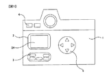
図1は本実施形態におけるデジタルスチルカメラの概略背面図である。カメラ本体1の背面には、液晶モニタ2および操作部材3,4,5が設けられている。液晶モニタ2は矩形の表示画面2Aを持ち、この画面2A上に撮影済みの画像を表示したり、カメラの種々の設定情報等を表示する。また後述するようにカスタム設定を行う際にも液晶モニタ2が用いられる。操作部材3はメニューボタンであり、これは画面2Aに種々の設定のためのメニュー画面(例えば、図3)を表示したりその表示を解除するためのものである。操作部材4はモニタボタンであり、これは画面2Aに撮影済み画像を表示したりその表示を解除するためのものである。
【0007】
操作部材はマルチセレクタ5であり、図2に示すように上下左右の4つの押圧部5a〜5dを有している。上下の押圧部5a,5bは、メニュー画面の上下方向に並んだ選択肢(項目や機能)からいずれかを選択する際に用いられる。押圧部5aの押圧操作により選択項目や機能が上方に変更され、押圧部5bの押圧操作により下方に変更される。右側の押圧部5cは決定ボタンに相当し、これを押圧操作すると画面2A上で選択されている項目や機能が決定される。左側の押圧部5dは、選択されている項目に対する数値や機能を選択するためのものである。また、後述するように測光範囲を示す円を表示する際にも押圧部5dが用いられる。
【0008】
上述した操作部材3〜5の操作信号は図15に示すCPU51に入力され、CPU51は、それらの操作信号に応答して表示駆動回路52により液晶モニタ2による表示制御を行う。
【0009】
次に、本実施形態における測光範囲の変更について説明する。
本実施形態では、カメラの測光モードとして、分割測光,中央部重点測光,スポット測光などが設定可能とされる。そのうち中央部重点測光は、撮影画面の中央部に設定した中央部重点測光範囲とその周囲の領域を別々に測光し、中央部重点測光範囲の測光出力の重み付けを周囲よりも重くして露出演算を行うものである。この測光方式は、例えば中央部重点平均測光などとも呼称されるが、本実施形態では中央部重点測光と呼ぶ。また中央部重点測光範囲は円形であるものとし、その大きさ(径)が可変とされる。この中央部重点測光範囲の変更自体は従来カメラにおいても可能であるが、本実施形態では、変更の際に中央部重点測光範囲を画面2Aに図形で表示できる点が従来と相違する。以下、この相違点について詳述する。
【0010】
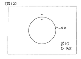
カスタム設定により中央部重点測光範囲の変更を指定すると、液晶モニタ2の画面2Aに図6に示すような測光範囲変更画面が表示される。この状態でマルチセレクタ5の押圧部5a,5bを操作することで、中央部重点測光範囲の大きさをφ6mm,φ8mm,φ10mm,φ13mmの中から選択できる。図6はφ8mmが選択されている例を示している。次いで押圧部5dを操作すると、図7に示すように選択された測光範囲を示す図形(円)60が画面2A上に表示されるとともに、その径を示す数値(φ8)が表示される。数値の下のマークは、押圧部5cを操作すれば選択されている測光範囲が決定される旨の表示である。
【0011】
ここで、円60は液晶モニタ2の画面2A全体を撮影画面と見立てた場合の中央部重点測光範囲を示している。正確には円60の内部が中央部重点測光範囲であり、円周は中央部重点測光範囲と周辺領域との境界を示す。これを見た操作者は、撮影画面における中央部重点測光範囲の位置およびその占める割合がどの程度であるかを直感的に把握できる。
【0012】
さらに、図7の状態でモニタボタン4を操作すると、円60はそのままで、画像が画面2Aに表示される(図8)。ここでいう画像とは、CCD等の撮像素子にて撮像され所定の処理が施された画像データである。これは現在撮影レンズが正対している被写体の画像をリアルタイムで表示してもよいし、メモリカードに記録されている画像を読み出して表示してもよい。
【0013】
図8の状態で押圧部5aまたは5bを押圧すると、中央部重点測光範囲の大きさ(選択値)が変更され、例えば図9,図10に示すように画面2A上の円60の大きさもそれに応じて変更される。このように被写体に重ね合わせて測光範囲をスーパーインポーズ表示できるので、操作者は被写体に対して正確に中央部重点測光範囲を設定することができる。例えば、図8〜図10のような人物撮影で被写体の顔の部分を重点的に測光したい場合には、顔の大きさに応じて最適な中央部重点測光範囲を設定できる。最適な測光範囲が表示できたら、押圧部5cを操作することで、そのとき表示されている測光範囲が決定され、次回からの測光に反映される。
また上述したような測光範囲の変更および決定は、撮影画像が表示されておらず円60のみが表示されている状態でも可能である(図7,図11,図12)。
【0014】
上記の動作をソフト的に実現するためのフローチャートを図13,図14に示す。これはCPU51によって実行されるもので、無関係の動作は省略してある。
メニューボタン3の操作に応答してこのプログラムが起動され、まず液晶モニタ2の画面2A上に図3のようなメニュー画面が表示される(ステップS1)。この状態でマルチセレクタ5の押圧部5a,5bを適宜操作すると図4のようなカスタムメニュー画面となり、更に押圧部5cを操作するとカスタム設定の変更が許容される(ステップS2,S3)。
【0015】
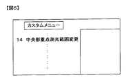
次いで押圧部5a,5bを適宜操作すると、図5に示す中央部重点測光範囲変更が選択され、更に押圧部5cを操作することで図6の画面となる(ステップS4,S5)。この図6の画面が表示されると、処理はステップS6〜S8のループを回り、マルチセレクタ5のいずれかの押圧部5a〜5dの操作待ちとなる。このとき操作部5aまたは5bが操作されると、中央部重点測光範囲の選択が変更され(ステップS6→S9)、再び上記ループに戻る。また押圧部5cが押圧されると、選択されている中央部重点測光範囲が決定され(ステップS7→S10)、最初のメニュー画面に戻る(ステップS1)。
【0016】
一方、上記ループを回っているときに押圧部5dが操作されると、ステップS8から図14のステップS11に進み、選択されている中央部重点測光範囲が円で表示される(例えば、図7)。次いでステップS12〜S14のループにて押圧部5a〜5cまたはモニタボタン4の操作待ちとなる。このとき押圧部5aまたは5bが操作されると、測光範囲の選択が変更されるとともに、その変更に応じて測光範囲を示す円の大きさが変更される(ステップS12→S15:図11,図12)。また操作部5cが操作されると、選択されている中央部重点測光範囲が決定され(ステップS13→S16)、その後、メニュー画面に戻る(ステップS1)。
【0017】
一方、ステップS12〜S14のループを回っているときにモニタボタン4が操作されると、現在撮影済みの画像が表示されているか否かが判定される(ステップS14→S17)。表示されていなければ画像が表示され(ステップS18)、これにより画像と測光範囲とが重ね合わされた表示となる。既に画像が表示されている場合には、画像の表示が解除される(ステップS19)。
なお、図13,図14の処理中にメニューボタン3が操作されると、メニュー表示やカスタム設定が解除され、通常の表示に戻る。
【0018】
なお、図13,図14の処理は一例を示したものであり、測光範囲の変更手順は上述のものに限定されない。また、以上では中央部重点測光範囲を例に挙げたが、例えば画面周辺領域は測光せず、画面中央部分のみの測光出力を用いて露出演算を行う方式(部分測光と呼ばれることもある)でもよい。さらに重点測光範囲は円以外の形状(例えば、楕円)でもよい。また上述の実施形態では、重点測光範囲の形状そのものは不変であり、大きさのみを変更可能な例を示したが、形状そのものを変更可能なものでもよい。例えば、円から楕円に変更したり、楕円の形状を変更可能なものでもよい。また重点測光範囲の位置も画面中央に限定されず、数も1個に限定されない。
【0019】
【発明の効果】
本発明によれば、モニタ装置の表示画面に、表示画面を撮影画面に見立てた場合の重点測光範囲を図形で表示できるようにしたので、数値のみの表示と比べて撮影画面における中央部重点測光範囲の占める割合を直感的に把握でき、最適な測光範囲を設定できる。
【図面の簡単な説明】
【図1】本発明の一実施形態におけるデジタルスチルカメラの概略背面図。
【図2】上記カメラのマルチセレクタ(操作部材)を示す図。
【図3】メニュー画面の一例を示す図。
【図4】カスタムメニュー画面を示す図。
【図5】中央部重点測光範囲の変更を選択した画面を示す図。
【図6】中央部重点測光範囲の変更画面を示す図。
【図7】中央部重点測光範囲を円で表示した画面を示す図。
【図8】中央部重点測光範囲を撮影画像に重ね合わせて表示した画面を示す図。
【図9】図8と同様の図であり、中部重点測光範囲を大きくした状態を示す。
【図10】図8と同様の図であり、中央部重点測光範囲を更に大きくした状態を示す。
【図11】図7と同様の図であり、中央部重点測光範囲を小さくした状態を示す。
【図12】図7と同様の図であり、中央部重点測光範囲を大きくした状態を示す。
【図13】中央部重点測光範囲の大きさ変更時の処理手順を示すフローチャート。
【図14】図13に続くフローチャート。
【図15】カメラの制御系を示すブロック図。
【符号の説明】
1 カメラ本体
2 液晶モニタ
2A 表示画面
3 メニューボタン
4 モニタボタン
5 マルチセレクタ
51 CPU
52 表示駆動回路
60 測光範囲を示す円[0001]
BACKGROUND OF THE INVENTION
The present invention relates to a digital still camera having a monitor device such as a liquid crystal monitor and having a specific photometric range set on a part of a photographing screen.
[0002]
[Prior art]
As a camera metering mode, there is center-weighted metering that focuses on the center of the shooting screen. Conventionally, there is a digital still camera that can change the size of the center-weighted metering range in the center-weighted metering. The change is made in the custom setting of the camera, and a plurality of selectable photometry range sizes are displayed on the screen of the liquid crystal monitor, and one of them is selected and determined.
[0003]
[Problems to be solved by the invention]
However, in the configuration in which the size of the photometric range is displayed only as a numerical value, it is difficult to grasp the ratio of the center-weighted photometric range in the entire screen, and there is a problem that it is not always possible to set the optimal photometric range for the photographer.
[0004]
An object of the present invention is to provide a digital still camera in which the proportion of the important metering range in the photographing screen can be intuitively grasped.
[0005]
[Means for Solving the Problems]
The present invention is applicable to a digital still camera that can perform a metering method that focuses light on a priority metering range set in a photographing screen and can change the priority metering range.
Then, have a display screen, along with the choice of the size of the plurality of center-weighted metering range is listed, a first screen any options have been selected is indicated, one of the alternatives A monitor device capable of displaying on the display screen a second screen for displaying the center-weighted metering range as a graphic when the display screen is regarded as a shooting screen, and a change operation for instructing to change the center-weighted metering range, And an operation device capable of switching between the first and second screens, and when the change operation is performed by the operation member when the first screen is displayed on the display screen, the center portion is emphasized according to the operation. When the metering range is changed and the switching operation is performed by the operating member when the first screen is displayed, the display is switched to the second screen, and the changing operation is performed when the second screen is displayed. When And a control unit for changing the shapes on the second screen according to the change with changing the center-weighted metering range in response to the operation, thereby solving the above problems.
Here, “changing the photometric range” in the claims means changing the size (area) without changing the shape of the photometric range, and changing the shape itself (for example, changing from a circle to an ellipse). ) It is a concept that includes cases. The term “focused metering” includes both the case where the metering output of only the keying metering range is used and the case where the metering output of another region is used but the weighting of the metering output in that range is increased.
According to the second aspect of the present invention, an image can be displayed on the display screen, and a graphic indicating the weighted metering range is displayed superimposed on the image.
In the invention of
The invention according to
[0006]
DETAILED DESCRIPTION OF THE INVENTION
An embodiment of the present invention will be described with reference to FIGS.
FIG. 1 is a schematic rear view of a digital still camera according to the present embodiment. A
[0007]
The operation member is a multi-selector 5 and has four pressing portions 5a to 5d on the top, bottom, left and right as shown in FIG. The upper and lower pressing
[0008]
The operation signals of the
[0009]
Next, the change of the photometric range in this embodiment will be described.
In the present embodiment, division photometry, center-weighted photometry, spot photometry, or the like can be set as the photometry mode of the camera. Of these, center-weighted metering measures the center-weighted metering range set in the center of the shooting screen and the surrounding area separately, and weights the metered output of the center-weighted metering range more heavily than the surroundings to calculate the exposure. Is to do. This metering method is also called, for example, center-weighted average metering, but in this embodiment is called center-weighted metering. The center-weighted photometric range is assumed to be circular, and its size (diameter) is variable. Although the center-weighted metering range itself can be changed by a conventional camera, the present embodiment is different from the prior art in that the center-weighted metering range can be displayed as a graphic on the
[0010]
When the change of the center-weighted photometry range is designated by the custom setting, a photometry range change screen as shown in FIG. 6 is displayed on the
[0011]
Here, a
[0012]
Furthermore, when the
[0013]
When the
Further, the change and determination of the photometric range as described above can be performed in a state in which the photographed image is not displayed and only the
[0014]
Flowcharts for realizing the above operation in software are shown in FIGS. This is intended to be executed by the C PU51, unrelated operations is omitted.
This program is activated in response to the operation of the
[0015]
Next, when the
[0016]
On the other hand, when the pressing portion 5d is operated while turning around the loop, the process proceeds from step S8 to step S11 of FIG. 14, and the selected center-weighted photometric range is displayed in a circle (for example, FIG. 7). ). Subsequently, the operation of the pressing portions 5a to 5c or the
[0017]
On the other hand, when the
If the
[0018]
Note that the processes in FIGS. 13 and 14 show an example, and the photometric range changing procedure is not limited to the above. In the above, the center-weighted metering range has been taken as an example. For example, a method of performing exposure calculation using a metering output of only the center portion of the screen without measuring the peripheral area of the screen (sometimes referred to as partial metering). Good. Furthermore, the weighted metering range may be a shape other than a circle (for example, an ellipse). In the above-described embodiment, the shape of the weighted metering range itself is not changed and only the size can be changed. However, the shape itself may be changed. For example, the shape may be changed from a circle to an ellipse, or the shape of the ellipse may be changed. Further, the position of the important metering range is not limited to the center of the screen, and the number is not limited to one.
[0019]
【The invention's effect】
According to the present invention, since the weighted metering range when the display screen is regarded as a shooting screen can be displayed as a graphic on the display screen of the monitor device, the center-weighted metering on the shooting screen is compared with the display of only the numerical value. The ratio of the range can be grasped intuitively and the optimum photometric range can be set.
[Brief description of the drawings]
FIG. 1 is a schematic rear view of a digital still camera according to an embodiment of the present invention.
FIG. 2 is a diagram illustrating a multi-selector (operation member) of the camera.
FIG. 3 is a diagram showing an example of a menu screen.
FIG. 4 is a diagram showing a custom menu screen.
FIG. 5 is a diagram showing a screen in which a change of the center-weighted photometry range is selected.
FIG. 6 is a diagram showing a screen for changing the center-weighted metering range.
FIG. 7 is a diagram showing a screen displaying a center-weighted metering range in a circle.
FIG. 8 is a diagram showing a screen in which a center-weighted metering range is displayed superimposed on a captured image.
FIG. 9 is a view similar to FIG. 8, showing a state in which the middle-weighted metering range is enlarged.
FIG. 10 is a view similar to FIG. 8, showing a state where the center-weighted photometry range is further enlarged.
FIG. 11 is a view similar to FIG. 7 and shows a state in which the center-weighted photometry range is reduced.
12 is a view similar to FIG. 7 and shows a state where the center-weighted photometry range is enlarged. FIG.
FIG. 13 is a flowchart showing a processing procedure when changing the size of the center-weighted metering range.
FIG. 14 is a flowchart following FIG. 13;
FIG. 15 is a block diagram showing a control system of the camera.
[Explanation of symbols]
1
52
Claims (4)
表示画面を有し、複数の中央部重点測光範囲の大きさの選択肢が一覧表示されるとともに、いずれの選択肢が選択されているかが明示される第1画面と、前記選択肢のいずれか1つについて、前記表示画面を前記撮影画面に見立てた場合の前記中央部重点測光範囲を図形で表示する第2画面とを前記表示画面に表示可能なモニタ装置と、
前記中央部重点測光範囲の変更を指示する変更操作、および前記第1,第2画面の切換操作が少なくとも可能な操作装置と、
前記表示画面に前記第1画面が表示されているときに前記操作部材により前記変更操作がなされると、その操作に応じて前記中央部重点測光範囲を変更し、前記第1画面が表示されているときに前記操作部材により前記切換操作がなされると、前記第2画面に表示を切換え、前記第2画面が表示されているときに前記変更操作がなされると、その操作に応じて前記中央部重点測光範囲を変更するとともにその変更に応じて前記第2画面上の前記図形を変更する制御装置とを備えることを特徴とするデジタルスチルカメラ。In a digital still camera that is capable of metering that focuses on the center-weighted metering range set in the shooting screen and that can change the center-weighted metering range,
Have a display screen, for with choice in the size of the plurality of center-weighted metering range is listed, a first screen any options have been selected is indicated, one of the alternatives A monitor device capable of displaying on the display screen a second screen for displaying the center-weighted metering range as a graphic when the display screen is regarded as the photographing screen ;
A change operation for instructing to change the center-weighted metering range, and an operation device capable of at least a switching operation of the first and second screens ;
When the change operation is performed by the operation member while the first screen is displayed on the display screen, the center-weighted metering range is changed according to the operation, and the first screen is displayed. When the switching operation is performed by the operation member while the display is being performed, the display is switched to the second screen, and when the change operation is performed while the second screen is displayed, the center is changed according to the operation. A digital still camera comprising: a control device that changes a part-weighted metering range and changes the graphic on the second screen according to the change .
Priority Applications (1)
| Application Number | Priority Date | Filing Date | Title |
|---|---|---|---|
| JP2002143095A JP4135400B2 (en) | 2002-05-17 | 2002-05-17 | Digital still camera |
Applications Claiming Priority (1)
| Application Number | Priority Date | Filing Date | Title |
|---|---|---|---|
| JP2002143095A JP4135400B2 (en) | 2002-05-17 | 2002-05-17 | Digital still camera |
Publications (3)
| Publication Number | Publication Date |
|---|---|
| JP2003333383A JP2003333383A (en) | 2003-11-21 |
| JP2003333383A5 JP2003333383A5 (en) | 2005-09-29 |
| JP4135400B2 true JP4135400B2 (en) | 2008-08-20 |
Family
ID=29703200
Family Applications (1)
| Application Number | Title | Priority Date | Filing Date |
|---|---|---|---|
| JP2002143095A Expired - Fee Related JP4135400B2 (en) | 2002-05-17 | 2002-05-17 | Digital still camera |
Country Status (1)
| Country | Link |
|---|---|
| JP (1) | JP4135400B2 (en) |
-
2002
- 2002-05-17 JP JP2002143095A patent/JP4135400B2/en not_active Expired - Fee Related
Also Published As
| Publication number | Publication date |
|---|---|
| JP2003333383A (en) | 2003-11-21 |
Similar Documents
| Publication | Publication Date | Title |
|---|---|---|
| US9560261B2 (en) | Display control for a camera | |
| CN103095991B (en) | Camera | |
| US8289433B2 (en) | Image processing apparatus and method, and program therefor | |
| US9172881B2 (en) | Camera and method of controlling operation of same | |
| US11838642B2 (en) | Camera | |
| EP1972992B1 (en) | Image-capturing device | |
| KR20100091846A (en) | Photographing apparatus and photographing method | |
| JP2004363707A (en) | Display method and display device | |
| JP2004104673A (en) | Digital camera | |
| JP4135400B2 (en) | Digital still camera | |
| JP6263986B2 (en) | Electronic device, image processing method, and image processing program | |
| KR101812656B1 (en) | Digital photographing apparatus and control method thereof | |
| JP2007110434A (en) | Camera, photography condition setting device therefor, photography condition setting method for camera, program, and recording medium | |
| JP2006018057A (en) | Camera | |
| JP4783073B2 (en) | Camera, display control apparatus for the camera, and display control method therefor | |
| JP4274547B2 (en) | Electronic device setting screen display method and electronic device | |
| JP3620534B2 (en) | Electronic still camera device and photographing method of electronic still camera | |
| JP4449644B2 (en) | Digital still camera | |
| JP2003186100A (en) | Camera | |
| JP5407538B2 (en) | Camera and focus detection area display program | |
| JP2002221753A (en) | Menu display method of camera | |
| JP3060362B2 (en) | Display device | |
| JP2004045494A (en) | Camera | |
| JP2018113533A (en) | Imaging apparatus | |
| JP2019149805A (en) | Electronic apparatus and image processing method |
Legal Events
| Date | Code | Title | Description |
|---|---|---|---|
| A621 | Written request for application examination |
Free format text: JAPANESE INTERMEDIATE CODE: A621 Effective date: 20050506 |
|
| A521 | Request for written amendment filed |
Free format text: JAPANESE INTERMEDIATE CODE: A523 Effective date: 20050512 |
|
| A977 | Report on retrieval |
Free format text: JAPANESE INTERMEDIATE CODE: A971007 Effective date: 20080125 |
|
| A131 | Notification of reasons for refusal |
Free format text: JAPANESE INTERMEDIATE CODE: A131 Effective date: 20080205 |
|
| A521 | Request for written amendment filed |
Free format text: JAPANESE INTERMEDIATE CODE: A523 Effective date: 20080403 |
|
| TRDD | Decision of grant or rejection written | ||
| A01 | Written decision to grant a patent or to grant a registration (utility model) |
Free format text: JAPANESE INTERMEDIATE CODE: A01 Effective date: 20080513 |
|
| A01 | Written decision to grant a patent or to grant a registration (utility model) |
Free format text: JAPANESE INTERMEDIATE CODE: A01 |
|
| A61 | First payment of annual fees (during grant procedure) |
Free format text: JAPANESE INTERMEDIATE CODE: A61 Effective date: 20080526 |
|
| R150 | Certificate of patent or registration of utility model |
Ref document number: 4135400 Country of ref document: JP Free format text: JAPANESE INTERMEDIATE CODE: R150 Free format text: JAPANESE INTERMEDIATE CODE: R150 |
|
| FPAY | Renewal fee payment (event date is renewal date of database) |
Free format text: PAYMENT UNTIL: 20110613 Year of fee payment: 3 |
|
| FPAY | Renewal fee payment (event date is renewal date of database) |
Free format text: PAYMENT UNTIL: 20110613 Year of fee payment: 3 |
|
| FPAY | Renewal fee payment (event date is renewal date of database) |
Free format text: PAYMENT UNTIL: 20140613 Year of fee payment: 6 |
|
| S531 | Written request for registration of change of domicile |
Free format text: JAPANESE INTERMEDIATE CODE: R313531 |
|
| FPAY | Renewal fee payment (event date is renewal date of database) |
Free format text: PAYMENT UNTIL: 20140613 Year of fee payment: 6 |
|
| R350 | Written notification of registration of transfer |
Free format text: JAPANESE INTERMEDIATE CODE: R350 |
|
| FPAY | Renewal fee payment (event date is renewal date of database) |
Free format text: PAYMENT UNTIL: 20140613 Year of fee payment: 6 |
|
| R250 | Receipt of annual fees |
Free format text: JAPANESE INTERMEDIATE CODE: R250 |
|
| R250 | Receipt of annual fees |
Free format text: JAPANESE INTERMEDIATE CODE: R250 |
|
| R250 | Receipt of annual fees |
Free format text: JAPANESE INTERMEDIATE CODE: R250 |
|
| R250 | Receipt of annual fees |
Free format text: JAPANESE INTERMEDIATE CODE: R250 |
|
| R250 | Receipt of annual fees |
Free format text: JAPANESE INTERMEDIATE CODE: R250 |
|
| R250 | Receipt of annual fees |
Free format text: JAPANESE INTERMEDIATE CODE: R250 |
|
| R250 | Receipt of annual fees |
Free format text: JAPANESE INTERMEDIATE CODE: R250 |
|
| LAPS | Cancellation because of no payment of annual fees |