JP6149696B2 - Information processing apparatus, information processing method, and program - Google Patents
Information processing apparatus, information processing method, and program Download PDFInfo
- Publication number
- JP6149696B2 JP6149696B2 JP2013231279A JP2013231279A JP6149696B2 JP 6149696 B2 JP6149696 B2 JP 6149696B2 JP 2013231279 A JP2013231279 A JP 2013231279A JP 2013231279 A JP2013231279 A JP 2013231279A JP 6149696 B2 JP6149696 B2 JP 6149696B2
- Authority
- JP
- Japan
- Prior art keywords
- imaging
- image
- display
- setting
- layer
- Prior art date
- Legal status (The legal status is an assumption and is not a legal conclusion. Google has not performed a legal analysis and makes no representation as to the accuracy of the status listed.)
- Active
Links
Images


Classifications
-
- H—ELECTRICITY
- H04—ELECTRIC COMMUNICATION TECHNIQUE
- H04N—PICTORIAL COMMUNICATION, e.g. TELEVISION
- H04N23/00—Cameras or camera modules comprising electronic image sensors; Control thereof
- H04N23/60—Control of cameras or camera modules
- H04N23/62—Control of parameters via user interfaces
-
- G—PHYSICS
- G06—COMPUTING; CALCULATING OR COUNTING
- G06F—ELECTRIC DIGITAL DATA PROCESSING
- G06F3/00—Input arrangements for transferring data to be processed into a form capable of being handled by the computer; Output arrangements for transferring data from processing unit to output unit, e.g. interface arrangements
- G06F3/01—Input arrangements or combined input and output arrangements for interaction between user and computer
- G06F3/048—Interaction techniques based on graphical user interfaces [GUI]
- G06F3/0484—Interaction techniques based on graphical user interfaces [GUI] for the control of specific functions or operations, e.g. selecting or manipulating an object, an image or a displayed text element, setting a parameter value or selecting a range
- G06F3/04847—Interaction techniques to control parameter settings, e.g. interaction with sliders or dials
-
- G—PHYSICS
- G06—COMPUTING; CALCULATING OR COUNTING
- G06F—ELECTRIC DIGITAL DATA PROCESSING
- G06F3/00—Input arrangements for transferring data to be processed into a form capable of being handled by the computer; Output arrangements for transferring data from processing unit to output unit, e.g. interface arrangements
- G06F3/01—Input arrangements or combined input and output arrangements for interaction between user and computer
- G06F3/048—Interaction techniques based on graphical user interfaces [GUI]
- G06F3/0481—Interaction techniques based on graphical user interfaces [GUI] based on specific properties of the displayed interaction object or a metaphor-based environment, e.g. interaction with desktop elements like windows or icons, or assisted by a cursor's changing behaviour or appearance
- G06F3/0482—Interaction with lists of selectable items, e.g. menus
-
- G—PHYSICS
- G06—COMPUTING; CALCULATING OR COUNTING
- G06F—ELECTRIC DIGITAL DATA PROCESSING
- G06F3/00—Input arrangements for transferring data to be processed into a form capable of being handled by the computer; Output arrangements for transferring data from processing unit to output unit, e.g. interface arrangements
- G06F3/01—Input arrangements or combined input and output arrangements for interaction between user and computer
- G06F3/048—Interaction techniques based on graphical user interfaces [GUI]
- G06F3/0481—Interaction techniques based on graphical user interfaces [GUI] based on specific properties of the displayed interaction object or a metaphor-based environment, e.g. interaction with desktop elements like windows or icons, or assisted by a cursor's changing behaviour or appearance
- G06F3/0483—Interaction with page-structured environments, e.g. book metaphor
-
- G—PHYSICS
- G06—COMPUTING; CALCULATING OR COUNTING
- G06F—ELECTRIC DIGITAL DATA PROCESSING
- G06F3/00—Input arrangements for transferring data to be processed into a form capable of being handled by the computer; Output arrangements for transferring data from processing unit to output unit, e.g. interface arrangements
- G06F3/01—Input arrangements or combined input and output arrangements for interaction between user and computer
- G06F3/048—Interaction techniques based on graphical user interfaces [GUI]
- G06F3/0484—Interaction techniques based on graphical user interfaces [GUI] for the control of specific functions or operations, e.g. selecting or manipulating an object, an image or a displayed text element, setting a parameter value or selecting a range
- G06F3/04842—Selection of displayed objects or displayed text elements
-
- G—PHYSICS
- G09—EDUCATION; CRYPTOGRAPHY; DISPLAY; ADVERTISING; SEALS
- G09G—ARRANGEMENTS OR CIRCUITS FOR CONTROL OF INDICATING DEVICES USING STATIC MEANS TO PRESENT VARIABLE INFORMATION
- G09G5/00—Control arrangements or circuits for visual indicators common to cathode-ray tube indicators and other visual indicators
- G09G5/36—Control arrangements or circuits for visual indicators common to cathode-ray tube indicators and other visual indicators characterised by the display of a graphic pattern, e.g. using an all-points-addressable [APA] memory
- G09G5/37—Details of the operation on graphic patterns
- G09G5/377—Details of the operation on graphic patterns for mixing or overlaying two or more graphic patterns
-
- H—ELECTRICITY
- H04—ELECTRIC COMMUNICATION TECHNIQUE
- H04N—PICTORIAL COMMUNICATION, e.g. TELEVISION
- H04N23/00—Cameras or camera modules comprising electronic image sensors; Control thereof
- H04N23/60—Control of cameras or camera modules
- H04N23/63—Control of cameras or camera modules by using electronic viewfinders
- H04N23/631—Graphical user interfaces [GUI] specially adapted for controlling image capture or setting capture parameters
- H04N23/632—Graphical user interfaces [GUI] specially adapted for controlling image capture or setting capture parameters for displaying or modifying preview images prior to image capturing, e.g. variety of image resolutions or capturing parameters
-
- H—ELECTRICITY
- H04—ELECTRIC COMMUNICATION TECHNIQUE
- H04N—PICTORIAL COMMUNICATION, e.g. TELEVISION
- H04N23/00—Cameras or camera modules comprising electronic image sensors; Control thereof
- H04N23/60—Control of cameras or camera modules
- H04N23/63—Control of cameras or camera modules by using electronic viewfinders
- H04N23/633—Control of cameras or camera modules by using electronic viewfinders for displaying additional information relating to control or operation of the camera
-
- G—PHYSICS
- G06—COMPUTING; CALCULATING OR COUNTING
- G06F—ELECTRIC DIGITAL DATA PROCESSING
- G06F3/00—Input arrangements for transferring data to be processed into a form capable of being handled by the computer; Output arrangements for transferring data from processing unit to output unit, e.g. interface arrangements
- G06F3/01—Input arrangements or combined input and output arrangements for interaction between user and computer
- G06F3/048—Interaction techniques based on graphical user interfaces [GUI]
- G06F3/0487—Interaction techniques based on graphical user interfaces [GUI] using specific features provided by the input device, e.g. functions controlled by the rotation of a mouse with dual sensing arrangements, or of the nature of the input device, e.g. tap gestures based on pressure sensed by a digitiser
- G06F3/0488—Interaction techniques based on graphical user interfaces [GUI] using specific features provided by the input device, e.g. functions controlled by the rotation of a mouse with dual sensing arrangements, or of the nature of the input device, e.g. tap gestures based on pressure sensed by a digitiser using a touch-screen or digitiser, e.g. input of commands through traced gestures
Description
本開示は、情報処理装置、情報処理方法、及びプログラムに関する。 The present disclosure relates to an information processing apparatus, an information processing method, and a program.
特許文献1には、ユーザが複数のアイコンのうちいずれかを選択した場合に、当該選択されたアイコンに関連したサブメニューを表示する撮像装置が開示されている。
しかし、この技術では、ユーザは、撮像パラメータを変更したい場合、その撮像パラメータに対応するアイコンをまず選択する必要があった。このため、ユーザは、撮像パラメータに対応するアイコンがわからない場合、アイコンを1つずつ選択し、サブメニューから所望の撮像パラメータを探しだす必要があった。したがって、撮像パラメータを設定するのに非常に手間がかかっていた。 However, in this technique, when the user wants to change the imaging parameter, it is necessary to first select an icon corresponding to the imaging parameter. For this reason, when the user does not know the icon corresponding to the imaging parameter, the user has to select the icon one by one and search for the desired imaging parameter from the submenu. Therefore, it takes much time to set the imaging parameters.
そこで、ユーザが撮像パラメータを容易に設定することができる技術が求められていた。 Therefore, a technique that allows a user to easily set imaging parameters has been demanded.
本開示によれば、操作入力に応じて撮像に関する撮像パラメータの設定が可能な情報処理装置であって、撮像パラメータを設定するための撮像パラメータ設定画像が配置された複数のレイヤのうち、いずれかのレイヤを表示レイヤとして表示部に表示する制御を行い、かつ、表示レイヤを切り替える制御を行う制御部を備える、情報処理装置が提供される。 According to the present disclosure, an information processing apparatus capable of setting imaging parameters related to imaging according to an operation input, and any one of a plurality of layers in which imaging parameter setting images for setting imaging parameters are arranged There is provided an information processing apparatus including a control unit that performs control to display a display layer as a display layer on a display unit and performs control to switch display layers.
本開示によれば、撮像に関する撮像パラメータを設定するための撮像パラメータ設定画像が配置された複数のレイヤのうち、いずれかのレイヤを表示レイヤとして表示部に表示する制御を行い、かつ、表示レイヤを切り替える制御を行うことと、入力操作に応じて、撮像パラメータを設定する制御を行うことと、を含む、情報処理方法が提供される。 According to the present disclosure, control is performed to display any layer as a display layer on a display unit among a plurality of layers in which imaging parameter setting images for setting imaging parameters relating to imaging are arranged, and the display layer There is provided an information processing method including performing control for switching between and performing control for setting an imaging parameter in accordance with an input operation.
本開示によれば、コンピュータに、撮像に関する撮像パラメータを設定するための撮像パラメータ設定画像が配置された複数のレイヤのうち、いずれかのレイヤを表示レイヤとして表示部に表示する制御を行い、表示レイヤを切り替える制御を行い、かつ、操作入力に応じて撮像パラメータを設定する制御を行う制御機能を実現させる、プログラムが提供される。 According to the present disclosure, the computer is controlled to display one of the plurality of layers in which the imaging parameter setting image for setting the imaging parameter for imaging is arranged on the display unit as the display layer. There is provided a program that realizes a control function for performing control for switching layers and performing control for setting an imaging parameter in accordance with an operation input.
本開示によれば、操作入力に応じて撮像に関する撮像パラメータの設定が可能な情報処理システムであって、撮像パラメータを設定するための撮像パラメータ設定画像が配置された複数のレイヤのうち、いずれかのレイヤを表示レイヤとして表示部に表示する制御を行い、かつ、表示レイヤを切り替える制御を行う制御部を備える、情報処理システムが提供される。 According to the present disclosure, there is provided an information processing system capable of setting imaging parameters related to imaging according to an operation input, and any one of a plurality of layers in which imaging parameter setting images for setting imaging parameters are arranged An information processing system is provided that includes a control unit that performs control to display a display layer as a display layer on a display unit and performs control to switch the display layer.
本開示によれば、ユーザは、所望のレイヤに表示された所望の撮像パラメータ設定画像を用いて撮像パラメータを設定することができる。 According to the present disclosure, the user can set imaging parameters using a desired imaging parameter setting image displayed on a desired layer.
以上説明したように本開示によれば、ユーザは、撮像パラメータを容易に設定することができる。なお、本開示に係る技術による効果はここで記載された効果に限定されない。本開示に係る技術は、本明細書中に記載されたいずれかの効果、または他の効果を有するものであってもよい。 As described above, according to the present disclosure, the user can easily set the imaging parameters. In addition, the effect by the technique which concerns on this indication is not limited to the effect described here. The technology according to the present disclosure may have any of the effects described in the present specification or other effects.
以下に添付図面を参照しながら、本開示の好適な実施の形態について詳細に説明する。なお、本明細書及び図面において、実質的に同一の機能構成を有する構成要素については、同一の符号を付することにより重複説明を省略する。 Hereinafter, preferred embodiments of the present disclosure will be described in detail with reference to the accompanying drawings. In addition, in this specification and drawing, about the component which has the substantially same function structure, duplication description is abbreviate | omitted by attaching | subjecting the same code | symbol.
なお、説明は以下の順序で行うものとする。
1.第1の実施形態(情報処理装置が撮像及び表示を行う例)
1−1.情報処理装置による処理の概要
1−2.情報処理装置の構成
1−3.情報処理装置による基本的な処理
1−4.レイヤの表示例
1−4−1.第1の表示例
1−4−2.第2の表示例
1−4−3.第3の表示例
1−4−4.第4の表示例
1−5.撮像モード切り替え処理
1−6.ユーザ選択に基づくウィジェット画像決定処理
1−7.シーン選択に基づくウィジェット画像決定処理
1−8.表示部の使用状態に基づく表示制御
1−9.他の処理
2.第2の実施形態(情報処理装置が表示を行い、撮像装置が撮像を行う例)
2−1.情報処理システムの全体構成
2−2.撮像装置の構成
2−3.情報処理システムによる処理
The description will be made in the following order.
1. First embodiment (an example in which an information processing apparatus performs imaging and display)
1-1. Overview of processing by information processing apparatus 1-2. Configuration of information processing apparatus 1-3. Basic processing by information processing apparatus 1-4. Display example of layer 1-4-1. First display example 1-4-2. Second display example 1-4-3. Third display example 1-4-4. Fourth display example 1-5. Imaging mode switching processing 1-6. Widget image determination process based on user selection 1-7. Widget image determination processing based on scene selection 1-8. Display control based on usage state of display unit 1-9. Other processing Second Embodiment (Example in which an information processing apparatus performs display and an imaging apparatus performs imaging)
2-1. Overall configuration of information processing system 2-2. Configuration of imaging apparatus 2-3. Processing by information processing system
<1.第1の実施形態>
(1−1.情報処理装置による処理の概要)
第1の実施形態に係る情報処理装置10は、概略的には、撮像に関する撮像パラメータを設定するためのウィジェット画像(撮像パラメータ設定画像)が配置された複数のレイヤを生成する。具体的には、情報処理装置10は、撮像モードにもとづいて、各レイヤに配置するウィジェット画像を決定する。そして、情報処理装置10は、ウィジェット画像を各レイヤに配置する。一方、情報処理装置10は、撮像を行うことで、スルー画像を生成する。そして、情報処理装置10は、いずれかのレイヤを表示レイヤとし、表示レイヤをスルー画像に重畳させて表示部に表示する。表示レイヤには、一又は複数のウィジェット画像が配置(表示)されている。
<1. First Embodiment>
(1-1. Overview of processing by information processing apparatus)
The
本実施形態におけるウィジェット画像には、撮像パラメータを設定するための画像、より具体的には撮像パラメータを設定するための入力操作が可能な画像が含まれる。撮像パラメータは、撮像に関するパラメータであり、特にその種類は問わない。撮像パラメータとしては、例えば、シャッタースピード(Tv)、絞り値(Av)、ISO値、撮像モード、フォーカス、ダイナミックレンジ、パノラマ、画角補正、色相補正、露出補正、各種編集情報、画質補正(美肌補正等)等が挙げられる。撮像モードには、露出モードが含まれる。ウィジェット画像は、ユーザ操作により表示位置及びサイズが任意に変更可能であってもよい。また、ウィジェット画像には、現在の撮像パラメータを表示する画像(例えば後述するウィジェット画像700、910等)を含めてもよい。
The widget image in the present embodiment includes an image for setting an imaging parameter, more specifically, an image capable of an input operation for setting an imaging parameter. The imaging parameter is a parameter related to imaging, and the type thereof is not particularly limited. Examples of imaging parameters include shutter speed (Tv), aperture value (Av), ISO value, imaging mode, focus, dynamic range, panorama, angle of view correction, hue correction, exposure correction, various editing information, image quality correction (skin tone) Correction etc.). The imaging mode includes an exposure mode. The display position and size of the widget image may be arbitrarily changed by a user operation. The widget image may include an image that displays the current imaging parameter (for example,
また、情報処理装置10は、例えばタッチパネル106からなる操作部15を備えており、ユーザが操作部15を用いて行った各種入力操作に応じた処理を行う。例えば、情報処理装置10は、ユーザが行った撮像パラメータ設定操作(例えばウィジェット画像上の所定の位置をタップする操作)に基づいて、撮像パラメータを調整する。さらに、情報処理装置10は、ユーザによるウィジェット画像移動操作(例えばドラッグ操作)に基づいて、ウィジェット画像を移動させる。さらに、情報処理装置10は、ユーザによるウィジェット画像拡大縮小操作(例えばピンチアウト、ピンチイン操作)に基づいて、ウィジェット画像の拡大縮小を行う。
In addition, the
さらに、情報処理装置10は、ユーザが行った表示レイヤ切り替え操作(例えば横フリック操作)に基づいて、表示レイヤを切り替える。さらに、情報処理装置10は、ユーザが行った撮像モード設定操作(例えば縦フリック操作)に基づいて、撮像モードを変更する。そして、情報処理装置10は、撮像モードに基づいて、各レイヤに配置するウィジェット画像を決定する。
Furthermore, the
さらに、情報処理装置10は、ユーザが設定画像選択操作(例えばウィジェットアイコンをレイヤ枠画像内にドラッグする操作。詳細は後述)によって選択したウィジェット画像を各レイヤに配置する。
Further, the
このように、ユーザは、各レイヤに配置するウィジェット画像を自由に選択することができ、かつ、各ウィジェット画像の配置、サイズを任意に調整することができる。すなわち、ユーザは、各レイヤを自由にカスタマイズすることができる。また、ユーザは、各レイヤに表示されたウィジェット画像を用いて撮像パラメータ設定操作を行うだけで撮像パラメータを調整することができる。したがって、本第1の実施形態によれば、ユーザは、撮像パラメータの設定を容易に行うことができる。 In this way, the user can freely select the widget images to be arranged on each layer, and can arbitrarily adjust the arrangement and size of each widget image. That is, the user can freely customize each layer. Further, the user can adjust the imaging parameters only by performing an imaging parameter setting operation using the widget images displayed on each layer. Therefore, according to the first embodiment, the user can easily set the imaging parameters.
(1−2.情報処理装置の構成)
つぎに、図1及び図2に基づいて、本実施形態に係る情報処理装置10の構成について説明する。
(1-2. Configuration of information processing apparatus)
Next, the configuration of the
図1に示すように、情報処理装置10は、記憶部11、通信部12、撮像部13、表示部14、操作部(入力操作部)15、及び制御部16を備える。記憶部11は、情報処理装置10に記憶部11、通信部12、撮像部13、表示部14、操作部15、及び制御部16を実現させるためのプログラム、及び各種画像情報(例えば各種ウィジェット画像)を記憶する。
As illustrated in FIG. 1, the
通信部12は、他の情報処理装置との間で通信を行う。撮像部13は、撮像を行う。具体的には、撮像部13は、ユーザが撮像操作(例えば図示しないシャッターボタンを押下する)を行うまでは、撮像素子に取り込まれた画像をスルー画像として制御部16に出力する。シャッターボタンはハードキーであってもよいし、表示部14に表示されたボタンであってもよい。撮像部13は、ユーザが撮像操作を行った場合には、Tv/Av値及びISO値の設定値に応じた撮像を行う(具体的には、シャッターを切る等の動作を行う)。そして、撮像部13は、撮像素子に取り込まれた画像を撮像画像として制御部16に出力する。
The
表示部14は各種画像、例えば上述したウィジェット画像及びスルー画像等を表示する。操作部15は、例えばタッチパネルであり、表示部14の表面に配置される。操作部15は、ユーザによる各種入力操作、例えば撮像パラメータ設定操作等が可能である。操作部15は、ユーザが行った入力操作に関する操作情報を制御部16に出力する。制御部16は、情報処理装置10全体を制御する他、入力操作を受け付けて各種処理を行う。また、制御部16は、各レイヤにウィジェット画像を配置する処理、各レイヤのうちいずれかを表示レイヤとして表示する制御等を行う。
The
情報処理装置10は、図2に示すハードウエア構成を有し、これらのハードウエア構成によって上記の記憶部11、通信部12、撮像部13、表示部14、操作部15、及び制御部16が実現される。
The
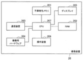
すなわち、情報処理装置10は、ハードウエア構成として、不揮発性メモリ101と、RAM102と、通信装置103と、撮像装置104と、ディスプレイ105と、タッチパネル106と、CPU107とを備える。
That is, the
不揮発性メモリ101は、各種プログラム及び画像情報等を記憶する。ここで、当該プログラムには、情報処理装置10に記憶部11、通信部12、撮像部13、表示部14、操作部15、及び制御部16を実現させるためのプログラムが含まれる。
The
RAM102は、CPU107による作業領域となるものである。通信装置103は、他の情報処理装置と通信を行う。撮像装置104は、撮像を行うことで、撮像画像を生成する。ディスプレイ105は、各種画像情報を表示する。ディスプレイ105は、音声情報を出力しても良い。タッチパネル106は、ユーザによる各種入力操作を受け付ける。
The
CPU107は、不揮発性メモリ101に記憶されたプログラムを読みだして実行する。したがって、CPU107が不揮発性メモリ101に記憶されたプログラムを読みだして実行することで、情報処理装置10に記憶部11、通信部12、撮像部13、表示部14、操作部15、及び制御部16が実現される。すなわち、CPU107は、情報処理装置10の実質的な動作主体となりうるものである。
The
情報処理装置10は、具体的には、例えばスマートフォン、スマートタブレット等であるが、上記の要件を満たすものであれば特に制限されない。例えば情報処理装置10は上記の構成を有する撮像装置であってもよい。ただし、スマートフォン、スマートタブレットは、撮像装置よりも表示画面が広いことが多いので好ましい。また、操作部15の具体例はタッチパネルであるが、他の操作装置であってもよい。すなわち、上述した各種入力操作を行うことができるものであれば特に制限されず、例えば十字キー、ダイヤル等のハードキーであってもよい。また、これらのハードキーとタッチパネルとを併用してもよい。例えば、微細な操作をハードキーで行うようにしてもよい。ただし、タッチパネルが操作部15の具体例として好ましい。特に、情報処理装置10がスマートフォン、スマートタブレット等となる場合、タッチパネルが操作部15の具体例として好ましい。スマートフォン、スマートタブレット等のユーザにとって、ハードキーの操作は煩雑に感じる可能性があるからである。また、ハードキーを併用した操作では、ユーザは、ハードキーを確認しながら撮像を行う必要があるので、撮像操作が分断される可能性がある。例えば、ユーザは、ハードキーの確認と表示部14の表示とを別々に確認する必要が生じうる。
Specifically, the
(1−3.情報処理装置による基本的な処理)
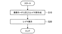
次に、情報処理装置10による基本的な処理の手順を図3に示すフローチャートに沿って説明する。
(1-3. Basic processing by information processing apparatus)
Next, a basic processing procedure performed by the
ステップS10において、情報処理装置10は、現在の撮像モードに基づいて、複数のレイヤ(レイヤ群)を作成する。具体的には、制御部16は、現在の撮像モードに基づいて、各レイヤに配置するウィジェット画像を決定(選択)する。すなわち、撮像モード毎にユーザの撮像目的が異なる。例えば、撮像モードがシャッタースピード優先モードとなる場合、ユーザは、高速シャッターによる撮像を行う可能性が高い。また、撮像モードが絞り優先モードとなる場合、ユーザは、被写体以外をぼかした撮像を行う可能性が高い。そこで、制御部16は、ユーザの撮像目的に応じた(適した)ウィジェット画像を選択する。
In step S10, the
ここで、撮像モードは特に制限されない。撮像モードとしては、例えば、各種露出モード、パノラマモード、各種シーンモード、編集モード、プレビューモード、再生モード、録画(REC)モード等が挙げられる。ここで、露出モードとしては、例えば、オートモード、マニュアルモード、絞り優先モード、シャッタースピード優先モード等が挙げられる。また、シーンモードとしては、スポーツ、夜間、マクロ、風景、ナイトポートレート、日没等が挙げられる。 Here, the imaging mode is not particularly limited. Examples of the imaging mode include various exposure modes, panoramic modes, various scene modes, editing modes, preview modes, playback modes, and recording (REC) modes. Here, examples of the exposure mode include an auto mode, a manual mode, an aperture priority mode, and a shutter speed priority mode. Examples of the scene mode include sports, night, macro, landscape, night portrait, sunset, and the like.
制御部16は、現在の撮像モードがプログラムモードとなる場合、ウィジェット画像として、例えば露出(Tv/Av)、ISO、シーンモード、ドライブモード(特にセルフタイマー)、ピクチャーエフェクトなどを設定するためのウィジェット画像を選択する。
When the current imaging mode is the program mode, the
また、制御部16は、現在の撮像モードが絞り優先モードとなる場合、ウィジェット画像として、クリエイティブスタイル、美肌効果、マニュアルフォーカス、フォーカス拡大、水準器等を設定するためのウィジェット画像を選択する。
In addition, when the current imaging mode is the aperture priority mode, the
また、制御部16は、現在の撮像モードがシャッタースピード優先モードとなる場合、ウィジェット画像として、ドライブモード(特に連写モード)、オートフォーカス(AF−C/AF−D)、追尾フォーカス、ブラケット撮像、ISO等を設定するためのウィジェット画像を選択する。
In addition, when the current imaging mode is the shutter speed priority mode, the
また、制御部16は、現在の撮像モードがマニュアルモードとなる場合、ウィジェット画像として、ISO、ホワイトバランス、ダイナミックレンジ、画質等を設定するためのウィジェット画像を選択する。
Further, when the current imaging mode is the manual mode, the
また、制御部16は、現在の撮像モードがオートモードとなる場合、後述する処理により撮像シーンを選択し、その撮像シーンに基づいてウィジェット画像を選択してもよい。なお、上記はあくまで一例であり、撮像シーン毎に上記以外のウィジェット画像を選択してもよい。
In addition, when the current imaging mode is the auto mode, the
そして、制御部16は、複数のレイヤを生成する。ここで、レイヤの数は1つでも良いが、複数であることが好ましい。制御部16は、各レイヤにレイヤ番号(例えば1以上の整数)を付与し、各レイヤにウィジェット画像を配置する。以下、レイヤ番号が「n(nは1以上の整数)」となるレイヤを「第nレイヤ」とも称する。
Then, the
制御部16は、撮像モードに基づいて各ウィジェット画像に優先度を設定し、レイヤ番号の小さいレイヤに優先度の高いウィジェット画像を配置してもよい。例えば、制御部16は、現在の撮像モードがプログラムモードとなる場合、上記で挙げたウィジェット画像のうち、露出、ISOを設定するためのウィジェット画像を第1レイヤに配置し、他のウィジェット画像を第2レイヤ以降に配置してもよい。また、各レイヤ内におけるウィジェット画像の配置は特に制限されない。制御部16は、他のパラメータ、例えばユーザによるウィジェット画像の使用頻度に基づいて優先度を決定してもよい。例えば、制御部16は、撮像モード毎にウィジェット画像の使用頻度を監視する。そして、制御部16は、いずれかの撮像モードが選択された場合、その撮像モードに対応する使用頻度にもとづいて、各ウィジェット画像の優先度を決定してもよい。例えば、制御部16は、ユーザによる使用頻度が高いほど優先度を高くしてもよい。
The
ステップS20において、撮像部13は、撮像を行い、これによって得られた撮像画像を制御部16に出力する。制御部16は、撮像画像をスルー画像として表示部14に表示する。さらに、制御部16は、各レイヤのうち、いずれかのレイヤ(初期状態では第1レイヤ)を表示レイヤとし、表示レイヤをスルー画像に重畳させて表示する。また、制御部16は、現在の表示レイヤのレイヤ番号を示す表示レイヤインジケータを表示する。
In step S <b> 20, the
制御部16は、ウィジェット画像に対する入力操作が行われた場合、その入力操作に応じて撮像パラメータを設定する。制御部16は、表示レイヤ中のウィジェット画像のうち、ユーザが操作中のウィジェット画像だけを表示するようにしてもよい。制御部16は、ユーザが操作中のウィジェット画像を拡大してもよい。
When an input operation is performed on the widget image, the
また、制御部16は、ユーザが表示レイヤ切り替え操作を行った場合に、表示レイヤを切り替える。例えば、制御部16は、ユーザが右フリック操作(図4中右方向に指をフリックする操作)を行った場合に、現在の表示レイヤよりもレイヤ番号が1大きいレイヤを表示レイヤとする。また、制御部16は、ユーザが左フリック操作(図4中左方向に指をフリックする操作)を行った場合に、現在の表示レイヤよりもレイヤ番号が1小さいレイヤを表示レイヤとする。
Moreover, the
ここで、制御部16は、現在の撮像モードに応じて表示レイヤ切り替え操作の方法を変更してもよい。例えば、制御部16は、撮像モードがスルー画像を表示するモードである場合には、横フリック操作を表示レイヤ切り替え操作としてもよい。また、制御部16は、撮像モードが撮像画像の編集モードとなる場合には、横フリックを表示レイヤ切り替え操作としてもよい。また、制御部16は、撮像モードが撮像画像の再生モードとなる場合、縦フリック操作(図4中上下方向に指をフリックする操作)を表示レイヤ切り替え操作としてもよい。制御部16は、横フリック操作が行われた場合に、表示中の撮像画像を切り替える。
Here, the
すなわち、制御部16は、撮像モード時の入力操作と表示レイヤ切り替え操作とが被らないように表示レイヤ切り替え操作の内容を決定してもよい。また、制御部16は、撮像モードに応じてウィジェット画像の表示のオンオフを切り替えてもよい。例えば、制御部16は、撮像モードがプレビューモードとなる場合には、ウィジェット画像を消去してもよい。制御部16は、撮像モードが録画モードとなる場合には、録画モードに適したウィジェット画像(例えば明るさ調整、逆光補正等を行うウィジェット画像等)だけを表示するようにしても良いし、ウィジェット画像を消去してもよい。その後、制御部16は、本処理を終了する。
That is, the
なお、制御部16は、現在の撮像モードに応じたウィジェット画像を選択し、それらを各レイヤに配置することとした。しかし、制御部16は、撮像モードによらず、予め設定されたウィジェット画像を各レイヤに配置してもよい。また、制御部16は、表示レイヤ切り替え操作に基づいて表示レイヤを変更するが、表示レイヤを自動的に切り替えてもよい。
Note that the
したがって、情報処理装置10は、ウィジェット画像を複数のレイヤに展開するので、ウィジェット画像の表示領域を広くとることができる。言い換えれば、情報処理装置10は、各ウィジェット画像同士の間隔を狭めて(すなわち省スペース化して)表示しなくてもよい。したがって、情報処理装置10は、ウィジェット画像の一覧性を向上する(すなわち視覚的にわかりやすくする)ことができる。
Therefore, since the
また、ユーザは、ウィジェット画像を操作(例えばタップ操作)することで撮像パラメータをダイレクトに設定できるので、撮像パラメータの設定に必要な操作を簡略化(省ステップ化)することができる。 Further, since the user can directly set the imaging parameter by operating the widget image (for example, a tap operation), the operation necessary for setting the imaging parameter can be simplified (step-saving).
また、ユーザは、所望のレイヤに所望のウィジェット画像を配置することができる。そして、ユーザは、表示レイヤを切り替えることで所望のウィジェット画像を表示させ、このウィジェット画像を用いて撮像パラメータを設定することができる。したがって、ユーザは、撮像パラメータを容易に設定することができる。特に、情報処理装置10がスマートフォン、スマートタブレット等となる場合、カメラ機能の使い勝手が向上する。この結果、いわゆるハイエンドユーザにとってカメラ機能がわかりやすいものになり、撮影体験がより身近になるものと期待される。したがって、スマートフォン、スマートタブレット等のユーザ層の拡大が期待される。
Also, the user can place a desired widget image on a desired layer. Then, the user can display a desired widget image by switching the display layer, and can set imaging parameters using the widget image. Therefore, the user can easily set the imaging parameters. In particular, when the
(1−4.レイヤの表示例)
(1−4−1.第1の表示例)
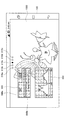
次に、レイヤの表示例について幾つか説明する。なお、以下に説明する内容はあくまで各レイヤの表示例であり、各レイヤには他のウィジェット画像を配置して良いことはもちろんである。図4は、第1レイヤの表示例を示す。制御部16は、制御部16は、スルー画像1000と、表示レイヤインジケータ210a〜210eと、ウィジェット画像300〜700とを表示する。すなわち、制御部16は、第1レイヤにウィジェット画像300〜700を配置する。
(1-4. Layer display example)
(1-4-1. First display example)
Next, some examples of layer display will be described. It should be noted that the content described below is a display example of each layer, and it is a matter of course that other widget images may be arranged in each layer. FIG. 4 shows a display example of the first layer. The
表示レイヤインジケータ210a〜210eは、表示レイヤのレイヤ番号を示すインジケータであり、それぞれレイヤ番号「1」〜「5」に対応する。制御部16は、表示レイヤに対応する表示レイヤインジケータ210aをハイライト表示する。すなわち、制御部16は、表示レイヤインジケータ210aを他の表示レイヤインジケータ210b〜210eとは異なる態様(例えば異なる色、輝度等)で表示する。制御部16は、表示レイヤ切り替え操作が行われた場合、表示レイヤを切り替えるとともに、現在の表示レイヤに対応するインジケータをハイライト表示する。
The
ウィジェット画像500は、撮像モードを設定(選択)するためのダイヤル画像である。すなわち、ウィジェット画像500には、撮像モードを示す撮像モード記号510が周方向に沿って複数描かれており、これらの撮像モード記号510のうち、左端の撮像モード記号520がハイライト表示されている。撮像モード記号520は、現在設定中の撮像モードを示す。すなわち、制御部16は、ユーザによる入力操作に応じてダイヤル画像500を回転させ、ダイヤル画像500の左端に表示された撮像モード記号520をハイライト表示する。そして、制御部16は、現在の撮像モードを撮像モード記号520が示す撮像モードに設定する。ダイヤル画像500を回転させるための入力操作としては、例えば、指をダイヤル画像500にタップし、その状態で指を円周方向に動かすこと等があげられる。図4の例では、マニュアルモード(M)が選択されている。第1レイヤ〜第5レイヤには、マニュアルモードに対応するウィジェット画像が配置されている。
The
ウィジェット画像600は、フォーカスモードを設定(選択)するための画像である。ウィジェット画像600には、複数のフォーカスモード記号610が描かれており、これらのフォーカスモード記号610のうち、いずれかのフォーカスモード記号620がハイライト表示されている。フォーカスモード記号620は、現在選択中のフォーカスモードを示す。制御部16は、例えばユーザがいずれかのフォーカスモード記号610をタップした場合には、タップされたフォーカスモード記号610をハイライト表示し、かつ、そのフォーカスモード記号610に対応するフォーカスモードに移行する。ウィジェット画像700は、現在設定中の撮像パラメータ(Tv/Av、ISO値等)を表示する。
The
ウィジェット画像300は、横軸310がTv、縦軸320がAvを示すウィジェット画像である。制御部16は、ユーザがウィジェット画像300上のいずれかの点をタップした場合、その点に点P1を表示する。さらに、制御部16は、Tv/Av値を点P1が示すTv/Av値に設定し、点P1が示すTv/Av値を横軸310及び縦軸320上でハイライト表示する。図4の例では、Tv値が1/250、Av値が2.8に設定されている。ここで、現在の撮像モードはマニュアルモードとなっているので、制御部16は、Tv/Av値に制限を設けない。したがって、ユーザは、ウィジェット画像300上の任意の点をタップすることで、Tv/Av値を選択(設定)することができる。
The
さらに、制御部16は、点P1を通る基準線330をウィジェット画像300上に表示する。基準線330上の各点が示すTv/Av値は、点P1と同じ露光量を示す。基準線330は、ウィジェット画像300の右上端部から外部に延長される。
Further, the
制御部16は、点P1の表示中にユーザが点P1以外の点をタップした場合、点P1をその点に移動する。そして、制御部16は、Tv/Av値を移動後の点P1が示すTv/Av値に設定する。さらに、制御部16は、基準線330をあらたな点P1に追従させる。
When the user taps a point other than the point P1 while the point P1 is being displayed, the
なお、ユーザがTv/Av値を選択(設定)する方法は、ウィジェット画像上の点をタップする方法に限られず、ウィジェット画像300上の点を選択できるものであれば特に制限されない。例えば、ユーザは、ドラッグアンドドロップ操作によりウィジェット画像300上の点を選択してもよい。例えば、制御部16は、ユーザが点P1をドラッグした場合、点P1をユーザの指に追従させ、ユーザが点P1をドロップした場合、その位置に点P1を表示する。制御部16は、タップとドラッグアンドドロップとを併用した操作を受け付けてもよい。そして、制御部16は、Tv/Av値を移動後の点P1が示すTv/Av値に設定する。
Note that the method of selecting (setting) the Tv / Av value by the user is not limited to the method of tapping a point on the widget image, and is not particularly limited as long as the point on the
ウィジェット画像400は、ISO値を選択するためのバー画像である。ウィジェット画像400の長さ方向上の各点は、ISO値を示し、上端点410はISO値の最大値を示し、下端点420はISO値の最小値を示す。図4の例では、最大値は16000,最小値は100となっているが、最大値及び最小値はこれらの例に限られない。制御部16は、ウィジェット画像400の上端点410の近傍に最大値表示画像410aを表示し、下端点420の近傍に最小値表示画像420aを表示する。
The
制御部16は、ウィジェット画像400をウィジェット画像300に関連付けて表示する。具体的には、制御部16は、基準線330と交差する位置にウィジェット画像400を表示する。より具体的には、制御部16は、ウィジェット画像400と基準線330とが交差する点P2が示すISO値をISO値の設定値とする。言い換えれば、制御部16は、ウィジェット画像400のうち、ISO値の設定値に対応する点P2と基準線330とを交差させる。また、制御部16は、ISO値の設定値を示す設定値表示画像430を点P2の近傍に表示する。
The
さらに、制御部16は、ユーザによる入力操作に応じてウィジェット画像400を矢印400a、または矢印400b方向に移動する。入力操作としては、例えば、ウィジェット画像400を指でタップし、指を矢印400a、または矢印400b方向にドラッグする方法があげられる。これによって、点P2が示す設定値も変動するので、制御部16は、ISO値を点P2が示す設定値に設定(変更)する。
Further, the
また、制御部16は、基準線330が移動した場合には、ウィジェット画像400を基準線330に追従させる。ここで、制御部16は、ISO値を現在の値に維持しても良いし、変更後のTv/Av値に応じた最適値(または予め設定された初期値)に変更してもよい。なお、本実施形態における「最適値」は、制御部16が最適と判断した値を意味する。前者の場合、制御部16は、ISO値が維持されるように、ウィジェット画像400の位置を調整する。すなわち、基準線330の移動前と移動後とで点P2のウィジェット画像400内での位置は不変である。後者の場合、制御部16は、Tv/Av値に応じたISO値の最適値を算出し、ISO値を当該最適値に設定する(または予め設定された初期値に設定する)。さらに、制御部16は、点P2が最適値(または初期値)を示すように、ウィジェット画像400の位置を調整する。
In addition, when the
なお、制御部16は、初期状態、すなわち図4に示す画像の表示を開始した状態では、Tv/Av値及びISO値の最適値を算出し、最適値に基づいて点P1の位置、基準線330の位置、及びウィジェット画像400の位置を調整する。
In the initial state, that is, in the state where the image display shown in FIG. 4 is started, the
また、ISO値を設定するための設定画像(第2の設定画像)はバー画像に限られない。例えば、第2の設定画像はダイヤル形状の画像であってもよい。このダイヤル画像は、例えばダイヤル画像500と同様に円周方向にISO値が描かれている。そして、制御部16は、ダイヤル画像上のいずれかのISO値と基準線330とを交差させる。制御部16は、基準線330と交差したISO値を設定値とする。
Further, the setting image (second setting image) for setting the ISO value is not limited to the bar image. For example, the second setting image may be a dial-shaped image. In this dial image, for example, the ISO value is drawn in the circumferential direction like the
また、制御部16は、スルー画像1000を現在の撮像パラメータ(例えばTv/Av値及びISO値)に応じて変動させてもよい。例えば、制御部16は、現在のTv/Av値及びISO値に応じてスルー画像1000をぼかす、流す等の処理を行ってもよい。この場合、ユーザは、現在の撮像パラメータに応じてスルー画像1000がどのように変動するのかを容易に把握することができる。
Further, the
また、制御部16は、Tv/Av値及びISO値の設定値を撮像操作毎にリセットしてもよく、維持してもよい。
In addition, the
また、制御部16は、撮像モードがオートモード(Tv/Av値及びISO値を自動で設定するモード)に設定されている場合、以下の処理を行ってもよい。すなわち、制御部16は、ユーザが撮像操作の予備操作(例えば撮像ボタンを半押しする操作)を行う毎に、Tv/Av値及びISO値の最適値を算出し、これに応じて点P1、基準線330、及びウィジェット画像400の位置を動的に変更してもよい。これにより、ユーザは、例えば撮像シーン毎にTv/Av値及びISO値がどのように変動するのかを容易に把握することができる。これにより、例えば初心者ユーザ及びハイアマチュアユーザは、撮像装置の仕組みをグラフィカルに理解することができる。この結果、初心者ユーザ及びハイアマチュアユーザは、Tv/Av値及びISO値に興味を持ち、ひいては、これらの撮像パラメータを自分で変更してみようとする意欲が沸くことが期待される。
Further, the
第1の表示例によれば、表示部14には、ウィジェット画像300及びウィジェット画像400が関連付けて表示されるので、ユーザは、これらの撮像パラメータの関連性を直感的に把握することができる。したがって、ユーザは、これらの撮像パラメータを直感的に設定することができる。なお、ユーザは、Tv/Av値を先に設定しても、ISO値を先に設定してもよい。
According to the first display example, since the
さらに、ユーザは、ウィジェット画像300上をタップする(またはドラッグアンドドロップする)ステップと、ウィジェット画像400を移動させるステップとの2ステップだけでTv/Av値及びISO値を設定することができる。したがって、ユーザは、これらの撮像パラメータを容易に設定することができる。さらに、制御部16は、ユーザ操作に応じてウィジェット画像300及びウィジェット画像400を変動させる(例えば点P1及び基準線330を移動させる、ウィジェット画像400を移動させる等)。したがって、ユーザは、これらの撮像パラメータをグラフィカルかつダイナミックに(フレキシブルに)設定することができる。
Furthermore, the user can set the Tv / Av value and the ISO value in only two steps: a step of tapping (or dragging and dropping) the
また、ベテランユーザは、各撮像パラメータを目で見て納得して撮像に移行することができる。初心者ユーザは、入力操作によって各撮像パラメータがどのように変動するのかを容易に把握することができる。この結果、初心者ユーザは、各撮像パラメータの設定に興味が湧くことが期待される。 Moreover, the veteran user can understand each imaging parameter visually and can shift to imaging. A novice user can easily grasp how each imaging parameter varies depending on an input operation. As a result, the novice user is expected to be interested in setting each imaging parameter.
さらに、情報処理装置10は、既存の撮像装置のユーザに対してより効率よい入力操作が可能なインタフェースを提供することができる。一方、情報処理装置10は、スマートフォンやスマートタブレット等のユーザのように、撮像装置に対して難しさを感じていたユーザに対する敷居を低減することができる。また、情報処理装置10による表示形態を撮像装置にも適用することで、撮像装置の商品形態が多様化し、より多くのユーザのニーズに応えることができるようになる。
Furthermore, the
なお、本発明者は、各撮像パラメータをハードキーのみ(例えばダイヤル、ボタン、十字キー等の任意の組み合わせ)で設定する技術についても検討した。しかし、この技術では、1つの撮像パラメータを設定するのに複数ステップの処理を要することが多い。また、ユーザにとっては、撮像パラメータ同士の関連性もわかりにくい。また、ハードキーの数、設置位置によって使い勝手が左右される。ハードキーが少ない場合、これらのハードキーを組み合わせて操作するケースが増大し、操作がより煩雑になりうる。また、特許文献1に開示された技術では、1つのサブメニューだけでは撮像パラメータが設定できない場合が多い。この場合、ユーザは、多数のサブメニュー(深い階層のサブメニュー)を辿ることで撮像パラメータを設定することになる。したがって、操作が煩雑になりうる。
The inventor has also studied a technique for setting each imaging parameter using only hard keys (for example, any combination of a dial, a button, a cross key, and the like). However, this technique often requires a plurality of steps of processing to set one imaging parameter. In addition, it is difficult for the user to understand the relationship between the imaging parameters. Usability depends on the number of hard keys and the installation position. When the number of hard keys is small, the number of cases in which these hard keys are operated in combination increases, and the operation can be more complicated. Also, with the technique disclosed in
(1−4−2.第2の表示例)
次に、図5に基づいて、第2の表示例について説明する。第2の表示例では、制御部16は、第3レイヤにウィジェット画像900、910を配置し、かつ、第3レイヤを表示レイヤとしている。また、制御部16は、表示レイヤインジケータ210cをハイライト表示する。
(1-4- 2. The second display example)
Next, a second display example will be described based on FIG. In the second display example, the
ウィジェット画像900はダイナミックレンジを設定(調整)するための画像であり、ゲージ画像900aと、矢印画像900bとを含む。ゲージ画像900aは、長さ方向に目盛が付された帯状の画像である。各目盛はダイナミックレンジの値を示す。矢印画像900bは、ゲージ画像900a中のいずれかの目盛を示す。制御部16は、ユーザの入力操作に応じて矢印画像900bを左右方向に移動させる。ここで、入力操作としては、矢印画像900bをドラッグアンドドロップする操作、ゲージ画像900a上の所望の点をタップする操作等があげられる。そして、制御部16は、ダイナミックレンジの設定値を矢印画像900bが示すダイナミックレンジに変更する。ウィジェット画像910は、横軸を画素の輝度、縦軸を頻度(画素の個数)としたヒストグラムである。
The
(1−4−3.第3の表示例)
次に、図6に基づいて、第3の表示例について説明する。第3の表示例では、制御部16は、第4レイヤにウィジェット画像920、930を配置し、かつ、第4レイヤを表示レイヤとしている。また、制御部16は、表示レイヤインジケータ210dをハイライト表示する。
(1-4-3. Third display example)
Next, a third display example will be described based on FIG. In the third display example, the
ウィジェット画像920は撮像画像の色相を設定(調整)するための画像であり、ゲージ画像920aを含む。ゲージ画像920aは、長さ方向に目盛が付された帯状の画像である。各目盛は色相の値を示す。また、ゲージ画像920aには、色相がグラデーション表示されている。
The
制御部16は、ユーザの入力操作に応じて色相を設定する。ここで、入力操作としては、ゲージ画像920a上の所望の点をタップする操作等があげられる。なお、制御部16は、ゲージ画像920a中のいずれかの目盛を示す矢印画像をゲージ画像920aの近傍に表示し、この矢印画像を入力操作に応じて移動させるようにしてもよい。そして、制御部16は、矢印画像が示す色相を現在の色相として設定してもよい。
The
ウィジェット画像930は撮像画像の露出補正量(明るさの補正量)を設定(調整)するための画像であり、ゲージ画像930aを含む。ゲージ画像930aは、長さ方向に目盛が付された帯状の画像である。各目盛は露出補正量の値を示す。また、ゲージ画像930aには、露出補正量がグラデーション表示されている。すなわち、露出補正量が大きい目盛ほど大きな輝度で表示される。
The
制御部16は、ユーザの入力操作に応じて露出補正量を設定する。ここで、入力操作としては、ゲージ画像930a上の所望の点をタップする操作等があげられる。なお、制御部16は、ゲージ画像930a中のいずれかの目盛を示す矢印画像をゲージ画像930aの近傍に表示し、この矢印画像を入力操作に応じて移動させるようにしてもよい。そして、制御部16は、矢印画像が示す露出補正量を現在の露出補正量として設定してもよい。
The
(1−4−4.第4の表示例)
次に、図7に基づいて、第4の表示例について説明する。第4の表示例では、制御部16は、第5レイヤにウィジェット画像940、950を配置し、かつ、第5レイヤを表示レイヤとしている。また、制御部16は、表示レイヤインジケータ210eをハイライト表示する。
(1-4-4. Fourth display example)
Next, a fourth display example will be described with reference to FIG. In the fourth display example, the
ウィジェット画像940は撮像画像の画像スタイル(表現スタイル)を設定(選択)するための画像である。画像スタイルは、彩度、明度、及びコントラストの組み合わせ等を示すものである。ウィジェット画像940には、複数の画像スタイルアイコン940a〜940fが含まれる。画像スタイルアイコン940a〜940fには、スルー画像に画像スタイルを適用したサンプル画像が描かれている。制御部16は、ユーザの入力操作に応じて画像スタイルを設定する。ここで、入力操作としては、いずれかの画像スタイルアイコン940a〜940fをタップする操作等があげられる。
The
ウィジェット画像950は、撮像画像の一部のカラーを設定(選択)するための画像である。ウィジェット画像950には、複数のカラー設定アイコン950a〜950dが含まれる。カラー設定アイコン950a〜950dには、スルー画像の一部を着色したサンプル画像が描かれている。制御部16は、ユーザの入力操作に応じてカラーを設定する。ここで、入力操作としては、いずれかのカラー設定アイコン950a〜950dをタップする操作等があげられる。
The
(1−5.撮像モード切り替え処理)
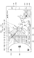
次に、撮像モード切り替え処理について図8に基づいて説明する。すなわち、制御部16は、ユーザが撮像モード設定操作(例えば縦フリック操作)を行った場合、図8に示すように、撮像モード設定画像800−1を表示する。
(1-5. Imaging mode switching process)
Next, the imaging mode switching process will be described with reference to FIG. That is, when the user performs an imaging mode setting operation (for example, a vertical flick operation), the
撮像モード設定画像800−1は、撮像モードを設定(選択)するための半円状のダイヤル画像であり、ウィジェット画像500と同様の機能を有する。すなわち、撮像モード設定画像800−1には、撮像モードを示す撮像モード記号810が周方向に沿って複数描かれており、これらの撮像モード記号810のうち、右端の撮像モード記号820がハイライト表示されている。撮像モード記号820は、現在設定中の撮像モードを示す。
The imaging mode setting image 800-1 is a semicircular dial image for setting (selecting) the imaging mode, and has the same function as the
そして、制御部16は、撮像モード設定操作に応じて撮像モード設定画像800−1を回転させる。例えば、制御部16は、撮像モード設定操作が上フリック操作となる場合、撮像モード設定画像800−1を左回転させる。一方、制御部16は、撮像モード設定操作が下フリック操作となる場合、撮像モード設定画像800−1を右回転させる。
And the
そして、制御部16は、撮像モード設定画像800−1の右端に表示された撮像モード記号820をハイライト表示する。そして、制御部16は、現在の撮像モードを撮像モード記号820が示す撮像モードに設定する。図8の例では、シャッタースピード優先モード(S)が選択されている。その後、制御部16は、撮像モード設定画像800−1を消去する。そして、制御部16は、現在の撮像モードであるシャッタースピード優先モード(S)に応じたウィジェット画像を選択し、各レイヤに配置する。具体的な配置方法は上述した通りである。
Then, the
なお、図8の例ではダイヤル画像500を省略したが、制御部16は、ダイヤル画像500を撮像モード設定画像800−1と共に表示してもよい。この場合、制御部16は、ダイヤル画像500を撮像モード設定画像800−1と同期させて回転させてもよい。ダイヤル画像500の撮像モード記号520と撮像モード設定画像800−1の撮像モード記号820とは同じ撮像モードを示す。
Although the
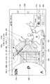
制御部16は、現在の撮像モードがシャッタースピード優先モードとなっており、かつ、ユーザが下フリック操作を行った場合、図9に示すように、撮像モード設定画像800−1を右回転させる。そして、制御部16は、絞り優先モード(A)を示す撮像モード記号820をハイライト表示する。そして、制御部16は、現在の撮像モードを絞り優先モードに設定する。その後、制御部16は、撮像モード設定画像800−1を消去する。そして、制御部16は、現在の撮像モードである絞り優先モードに応じたウィジェット画像を選択し、各レイヤに配置する。
When the current imaging mode is the shutter speed priority mode and the user performs a downward flick operation, the
制御部16は、現在の撮像モードが絞り優先モードとなっており、かつ、ユーザが下フリック操作を行った場合、図10に示すように、撮像モード設定画像800−1を右回転させる。そして、制御部16は、プログラムモード(P)を示す撮像モード記号820をハイライト表示する。そして、制御部16は、現在の撮像モードをプログラムモードに設定する。その後、制御部16は、撮像モード設定画像800−1を消去する。そして、制御部16は、現在の撮像モードであるプログラムモードに応じたウィジェット画像を選択し、各レイヤに配置する。
When the current imaging mode is the aperture priority mode and the user performs a downward flick operation, the
ここで、撮像モード設定画像は上記の例に限られない。以下、他の撮像モード設定画像の例について説明する。図11は、撮像モード設定画像の他の例として、撮像モード設定画像800−2を示す。撮像モード設定画像800−2は、ウィジェット画像500と同様に円形のダイヤル画像となっている。撮像モード設定画像800−2には、撮像モードを示す撮像モード記号810が周方向に沿って複数描かれており、これらの撮像モード記号810のうち、右端の撮像モード記号820がハイライト表示されている。撮像モード記号820は、現在設定中の撮像モードを示す。
Here, the imaging mode setting image is not limited to the above example. Hereinafter, examples of other imaging mode setting images will be described. FIG. 11 shows an imaging mode setting image 800-2 as another example of the imaging mode setting image. The imaging mode setting image 800-2 is a circular dial image like the
制御部16は、撮像モード設定操作に応じて撮像モード設定画像800−2を回転させる。例えば、制御部16は、撮像モード設定操作が上フリック操作となる場合、撮像モード設定画像800−2を左回転させる。一方、制御部16は、撮像モード設定操作が下フリック操作となる場合、撮像モード設定画像800−2を右回転させる。そして、制御部16は、撮像モード設定画像800−2の右端に表示された撮像モード記号820をハイライト表示する。そして、制御部16は、現在の撮像モードを撮像モード記号820が示す撮像モードに設定する。
The
図12は、撮像モード設定画像の他の例として、撮像モード設定画像800−3を示す。撮像モード設定画像800−3は、縦ベルト形状の画像となっている。撮像モード設定画像800−3には、撮像モードを示す撮像モード記号810が縦方向に複数描かれており、これらの撮像モード記号810のうち、中央の撮像モード記号820がハイライト表示されている。撮像モード記号820は、現在設定中の撮像モードを示す。
FIG. 12 shows an imaging mode setting image 800-3 as another example of the imaging mode setting image. The imaging mode setting image 800-3 is a vertical belt-shaped image. In the imaging mode setting image 800-3, a plurality of
制御部16は、撮像モード設定操作に応じて撮像モード設定画像800−3を縦方向に移動させる。例えば、制御部16は、撮像モード設定操作が上フリック操作となる場合、撮像モード設定画像800−3を上方向に移動させる。一方、制御部16は、撮像モード設定操作が下フリック操作となる場合、撮像モード設定画像800−3を下方向に移動させる。そして、制御部16は、撮像モード設定画像800−3の中央に表示された撮像モード記号820をハイライト表示する。そして、制御部16は、現在の撮像モードを撮像モード記号820が示す撮像モードに設定する。
The
図13は、撮像モード設定画像の他の例として、撮像モード設定画像800−4を示す。撮像モード設定画像800−4は、縦ダイヤル形状(スロット型)の画像となっている。撮像モード設定画像800−4には、撮像モードを示す撮像モード記号810が縦方向に複数描かれており、これらの撮像モード記号810のうち、中央の撮像モード記号820がハイライト表示されている。撮像モード記号820は、現在設定中の撮像モードを示す。
FIG. 13 shows an imaging mode setting image 800-4 as another example of the imaging mode setting image. The imaging mode setting image 800-4 is a vertical dial (slot type) image. In the imaging mode setting image 800-4, a plurality of
制御部16は、撮像モード設定操作に応じて撮像モード設定画像800−4を縦方向に回転させる。例えば、制御部16は、撮像モード設定操作が上フリック操作となる場合、撮像モード設定画像800−4を上方向に回転させる。一方、制御部16は、撮像モード設定操作が下フリック操作となる場合、撮像モード設定画像800−4を下方向に回転させる。そして、制御部16は、撮像モード設定画像800−4の中央に表示された撮像モード記号820をハイライト表示する。そして、制御部16は、現在の撮像モードを撮像モード記号820が示す撮像モードに設定する。
The
なお、制御部16は、撮像モード設定画像800−1〜800−4上の撮像モード記号810の並び順を任意に、もしくはユーザによる入力操作に応じて変更してもよい。ウィジェット画像500についても同様である。
Note that the
(1−6.ユーザ選択に基づくウィジェット画像決定処理)
上述したように、制御部16は、撮像モードに基づいて各レイヤに配置するウィジェット画像を決定する。さらに、制御部16は、ユーザによる入力操作(設定画像選択操作)に基づいて各レイヤに配置するウィジェット画像を決定してもよい。
(1-6. Widget image determination process based on user selection)
As described above, the
具体的には、制御部16は、ウィジェット画像選択モードに移行するための入力操作(例えば操作部15のいずれかの位置を長押しする操作)が行われた場合に、ウィジェット画像選択モードに移行する。
Specifically, the
制御部16は、ウィジェット画像選択モードに移行した場合、図14に示すように、レイヤ枠画像1010a、1010b、1010cと、ウィジェットアイコン一覧画像2000とを表示する。
When the
レイヤ枠画像1010aは、ウィジェット画像の配置対象となる配置対象レイヤ(初期状態では表示レイヤ)を示す。レイヤ枠画像1010bは、表示レイヤよりもレイヤ番号が1小さいレイヤを示し、レイヤ枠画像1010cは、表示レイヤよりもレイヤ番号が1大きいレイヤを示す。制御部16は、ユーザが配置対象レイヤ切り替え操作(例えば横フリック操作)を行った場合に、配置対象レイヤを切り替えてもよい。例えば、制御部16は、右フリック操作が行われた場合に、配置対象レイヤを現在の配置対象レイヤよりもレイヤ番号が1小さいレイヤとしてもよい。また、制御部16は、左フリック操作が行われた場合に、配置対象レイヤを現在の配置対象レイヤよりもレイヤ番号が1大きいレイヤとしてもよい。また、制御部16は、ウィジェット画像選択モード時には、表示レイヤインジケータ210a〜210eのうち、配置対象レイヤに対応するインジケータをハイライト表示してもよい。
The
ウィジェットアイコン一覧画像2000は、ベルト画像2000aと、回転(スクロール)指示ボタン2000b、2000cと、複数のウィジェットアイコン2010〜2060と、ウィジェット名称画像2010a〜2060aとを含む。ベルト画像2000aは、左右方向に伸びる帯状の画像であり、左右方向に回転(スクロール)が可能となっている。回転指示ボタン2000b、2000cは、ベルト画像2000aを左右方向に回転させるためのボタンである。すなわち、制御部16は、回転指示ボタン2000bがユーザによりタップされた場合、ベルト画像2000aを左方向に回転(スクロール)させる。一方、制御部16は、回転指示ボタン2000cがユーザによりタップされた場合、ベルト画像2000aを右方向に回転させる。制御部16は、横フリック操作によりベルト画像2000aを回転させてもよい。
The widget
ウィジェットアイコン2010〜2060は、ウィジェット画像をアイコンで示すものであり、ベルト画像2000aの長さ方向に沿って配置される。ウィジェット名称画像2010a〜2060aは、ウィジェットアイコン2010〜2060の下方に配置され、ウィジェット画像の名称を示す。
The
ユーザは、いずれかのウィジェットアイコンをレイヤ枠画像1010a内にドラッグする。これにより、ユーザは、ウィジェットアイコンに対応するウィジェット画像を選択する。制御部16は、ユーザにより選択されたウィジェット画像を配置対象レイヤ内に配置する。例えば、ユーザがウィジェットアイコン2040をレイヤ枠画像1010a内にドラッグした場合、制御部16は、図15に示すように、ウィジェット画像960を配置対象レイヤ(ここでは第3レイヤ)に配置する。
The user drags one of the widget icons into the
ここで、ウィジェット画像960は、ドライブモードを設定(選択)するための画像であり、ドライブモードを示す複数のドライブモードアイコン960aを含む。そして、いずれかのドライブモードアイコン960aがハイライト表示されている。ハイライト表示されたドライブモードアイコン960a、すなわちドライブモードアイコン960bは、現在設定中のドライブモードを示す。
Here, the
すなわち、制御部16は、ユーザがいずれかのドライブモードアイコン960aをタップした場合、そのドライブモードアイコン960aをハイライト表示する。そして、制御部16は、ハイライト表示されたドライブモードアイコン960a、すなわちドライブモードアイコン960bが示すドライブモードを現在のドライブモードとして設定する。
That is, when the user taps one of the
なお、制御部16は、ユーザ操作にもとづいて、ウィジェット画像選択モードを解除する。例えば、制御部16は、ユーザがレイヤ枠画像1010aを長押しした場合に、ウィジェット画像選択モードを解除する。
The
したがって、ユーザは、所望のレイヤに所望のウィジェット画像を配置することができる。例えば、ユーザは、撮像の目的に応じてウィジェット画像同士の組み合わせ等を自由にカスタマイズすることができる。 Therefore, the user can arrange a desired widget image on a desired layer. For example, the user can freely customize the combination of widget images according to the purpose of imaging.
また、制御部16は、ユーザがいずれかのウィジェット画像を選択した場合、そのウィジェット画像に関連する関連ウィジェット画像を提示(リコメンド)してもよい。例えば、制御部16は、関連ウィジェット画像をユーザが選択したウィジェット画像と同じレイヤまたは他のレイヤに配置してもよい。また、制御部16は、ベルト画像2000a上のウィジェットアイコンのうち、関連ウィジェット画像に対応するウィジェットアイコンをハイライト表示してもよい。また、制御部16は、音声にて関連ウィジェット画像を提示してもよい。
In addition, when the user selects any widget image, the
ここで、関連ウィジェット画像は、予め設定されていても良いし、ユーザによる使用履歴に基づいて設定されてもよい。後者の場合、例えば、制御部16は、複数のウィジェット画像が同じレイヤで使用された回数が所定値以上となる場合、これらのウィジェット画像が関連すると判定してもよい。
Here, the related widget image may be set in advance, or may be set based on a use history by the user. In the latter case, for example, when the number of times a plurality of widget images are used in the same layer is equal to or greater than a predetermined value, the
また、制御部16は、ユーザが選択したウィジェット画像にもとづいて、撮像モードを設定してもよい。例えば、制御部16は、パノラマモードに適したウィジェット画像(例えば画角補正等を設定するためのウィジェット画像)が選択された場合、撮像モードをパノラマモードに設定してもよい。
Further, the
(1−7.シーン選択に基づくウィジェット画像決定処理)
制御部16は、撮像モードに基づいて各レイヤに配置するウィジェット画像を決定する。ここで、撮像モードには、撮像シーンも含まれる。したがって、制御部16は、撮像シーンに基づいてウィジェット画像を決定してもよい。その例を図16及び図17に基づいて説明する。
(1-7. Widget image determination process based on scene selection)
The
制御部16は、撮像モードが撮像シーン選択モード(SCN)に設定された場合、図16に示すように、表示レイヤ(この例では第2レイヤ)に撮像シーン選択画像1020を配置する。もちろん、制御部16は、他のウィジェット画像を各レイヤに配置してもよい。
When the imaging mode is set to the imaging scene selection mode (SCN), the
撮像シーン選択画像1020は、撮像シーンを示す撮像シーンアイコン1020a〜1020fを含む。制御部16は、ユーザの入力操作に応じて撮像シーンを設定する。ここで、入力操作としては、いずれかの撮像シーンアイコン1020a〜1020fをタップする操作等があげられる。
The captured
制御部16は、撮像シーンを設定した場合には、撮像シーンにもとづいて、各レイヤに配置するウィジェット画像を決定する。例えば、制御部16は、撮像シーンが「ナイトポートレート」(撮像シーンアイコン1020eに対応)に設定された場合、図17に示すように、ウィジェット画像900、1030をいずれかのレイヤ(この例では第2レイヤ)に配置する。
When the imaging scene is set, the
ここで、ウィジェット画像1030は、美肌効果を設定(調整)するための画像であり、ゲージ画像1030aと、ポインタ1030bと、美肌効果設定ボタン1030c〜1030eとを含む。ゲージ画像1030aは、長さ方向に目盛が付された帯状の画像である。各目盛は美肌効果の作用量(撮像画像にどの程度美肌効果を施すかを示す量)を示す。ポインタ1030bは、現在の美肌効果の作用量を示す。
Here, the
制御部16は、ユーザの入力操作に応じてポインタ1030bを左右方向に移動させる。ここで、入力操作としては、ポインタ1030bをドラッグアンドドロップする操作、ゲージ画像1030a上の所望の点をタップする操作等があげられる。そして、制御部16は、美肌効果の作用量をポインタ1030bが示す値に変更する。
The
美肌効果設定ボタン1030c〜1030eは、調整対象となる美肌効果の種類を設定するためのボタンである。制御部16は、美肌効果設定ボタン1030c〜1030eのうち、ユーザがタップしたボタンに対応する美肌効果を調整する。
The skin-beautifying
(1−8.表示部の使用状態に基づく表示制御)
制御部16は、表示部14(ディスプレイ105)の使用状態が変更された場合に、ウィジェット画像同士の位置関係を維持する。また、制御部16は、ウィジェット画像が表示部14内に収まるように、ウィジェット画像の倍率を調整する。ここで、位置関係とは、各ウィジェット画像の他のウィジェット画像に対する表示位置を意味する。
(1-8. Display control based on usage state of display unit)
The
表示例を図18、図19に基づいて説明する。制御部16は、第1レイヤにウィジェット画像300〜700が配置され、かつ、表示部14が横置きで使用される場合、例えば図18に示す画像を表示する。制御部16は、表示部14の使用状態が縦置きに変更された場合、図19に示すように、ウィジェット画像300〜700同士の位置関係を維持し、ウィジェット画像300〜700を縮小する。例えば、図18では、ウィジェット画像300はウィジェット画像700の上側に表示されているので、制御部16は、表示部14の使用状態が縦置きに変更された場合でも、ウィジェット画像300をウィジェット画像700の上側に表示する。
Display examples will be described with reference to FIGS. For example, when the
もちろん、制御部16は、使用状態に応じてウィジェット画像同士の位置関係を調整してもよい。例えば、制御部16は、表示部14の使用状態が縦置きに変更された場合に、ウィジェット画像300〜700を上下方向に並べてもよい。
Of course, the
(1−9.他の処理)
次に、図20に基づいて他の処理について説明する。制御部16は、アンドゥボタン1110、リセットボタン1120、及びロックボタン1130を表示レイヤとともに表示してもよい。制御部16は、ユーザがアンドゥボタン1110をタップした場合、各画像の状態をユーザによる1手前の操作が行われた状態に戻す。制御部16は、リセットボタン1120がタップされた場合には、表示状態を初期状態に戻す。制御部16は、レイヤ毎に表示状態を初期状態に戻しても良いし、全レイヤの表示状態を初期状態に戻してもよい。制御部16は、表示状態を予め設定された状態に戻しても良い(いわゆるカスタムリセット)。この機能は、例えば情報処理装置10のデモンストレーション時に有用である。例えば、デモンストレータが一のユーザに情報処理装置10の操作を説明した場合、他のユーザに説明を開始する前に、カスタムリセットを行う。これにより、デモンストレータは、情報処理装置10の表示状態を一のユーザへの説明前の状態に簡単に戻すことができる。
(1-9. Other processing)
Next, another process will be described based on FIG. The
制御部16は、ロックボタン1130がタップされた場合には、ユーザによる入力操作を排除する(受け付けない)。制御部16は、ロックボタン1130が再度タップされた場合には、ユーザによる当該入力操作を受け付ける。なお、アンドゥボタン1110、リセットボタン1120、及びロックボタン1130のうちいずれかの表示が省略されていても良い。これらのボタンの一部はハードキーであってもよい。
When the
以上により、本実施形態によれば、情報処理装置10は、ウィジェット画像が配置された複数のレイヤのうち、いずれかのレイヤを表示レイヤとして表示部14に表示し、かつ、表示レイヤの切り替えを行う。さらに、情報処理装置10は、入力操作に応じて撮像パラメータを設定する。したがって、ユーザは、所望のレイヤに表示された所望のウィジェット画像を用いて撮像パラメータを設定することができるので、撮像パラメータを容易に設定することができる。
As described above, according to the present embodiment, the
また、情報処理装置10は、ユーザにより表示レイヤ切り替え操作が行われた場合に、表示レイヤを切り替える。したがって、ユーザは、所望のレイヤを容易に表示させることができる。
Further, the
また、情報処理装置10は、各レイヤに配置するウィジェット画像を撮像モードに基づいて決定するので、ユーザの撮像目的に応じたウィジェット画像を各レイヤに配置することができる。したがって、ユーザは、所望の撮像パラメータを容易に設定することができる。
Moreover, since the
また、情報処理装置10は、撮像モードに基づいて、ウィジェット画像の優先度を決定し、優先度に基づいて、各レイヤに配置するウィジェット画像を設定する。したがって、ユーザは、所望のウィジェット画像をより容易に発見することができる。
Further, the
また、情報処理装置10は、ユーザによる撮像モード設定操作が行われる際に、撮像モードを設定するための撮像モード設定画像を表示する。これにより、撮像モード設定画像がユーザにとって邪魔になりにくい。また、ユーザは、撮像モード設定画像を用いることで、撮像モードを所望のモードに容易に変更することができる。
The
また、情報処理装置10は、ユーザにより選択されたウィジェット画像を各レイヤに配置する制御を行う。したがって、ユーザは、所望のレイヤに所望のウィジェット画像を配置することができる。
In addition, the
さらに、情報処理装置10は、ユーザが選択したウィジェット画像に関連する関連ウィジェット画像を提示する制御を行う。これにより、ユーザは、所望の撮像に必要な撮像パラメータを容易に把握することができ、かつ、その撮像パラメータを容易に調整することができる。
Further, the
さらに、情報処理装置10は、関連ウィジェット画像をユーザが選択したウィジェット画像と同じレイヤまたは他のレイヤに表示してもよい。これにより、ユーザは、関連ウィジェット画像をレイヤに配置する手間が省ける。
Further, the
さらに、情報処理装置10は、ユーザが選択したウィジェット画像に基づいて、撮像モードを設定する。したがって、ユーザは、所望の撮像を容易に行うことができる。
Furthermore, the
さらに、情報処理装置10は、撮像モードに応じて表示レイヤ切り替え操作の方法を変更する。したがって、情報処理装置10は、ユーザが表示レイヤ切り替え操作と他の操作とを混同する可能性を低減することができる。
Furthermore, the
また、情報処理装置10は、表示部14の使用状態が変更された場合に、ウィジェット画像同士の位置関係を維持する。したがって、表示部14の使用状態が変更された場合であっても、ユーザが混乱する可能性が低下する。
Further, the
<2.第2の実施形態>
つぎに、第2の実施形態について説明する。第2の実施形態では、情報処理装置と撮像装置とが分割されている。
<2. Second Embodiment>
Next, a second embodiment will be described. In the second embodiment, the information processing apparatus and the imaging apparatus are divided.
(2−1.情報処理システムの全体構成)
まず、図21に基づいて、第2の実施形態に係る情報処理システムの構成について説明する。情報処理システムは、情報処理装置10及び撮像装置20を備える。情報処理装置10及び撮像装置20は、互いに通信する事が可能である。情報処理装置10は、上述した第1の実施形態と同様の処理を行う。ただし、情報処理装置10は、スルー画像及び撮像画像を撮像装置20との通信によって取得する。また、情報処理装置10は、撮像パラメータの設定値に関する設定値情報を撮像装置20に出力する。
(2-1. Overall configuration of information processing system)
First, the configuration of an information processing system according to the second embodiment will be described with reference to FIG. The information processing system includes an
(2−2.撮像装置の構成)
情報処理装置10の構成は第1の実施形態で示した通りである。なお、第2の実施形態では、情報処理装置10は撮像部13を有していなくてもよい。そこで、ここでは撮像装置20の構成について説明する。
(2-2. Configuration of Imaging Device)
The configuration of the
図22に示すように、撮像装置20は、記憶部21、通信部22、撮像部23、表示部24、操作部25、及び制御部26を備える。記憶部21は、撮像装置20に記憶部21、通信部22、撮像部23、表示部24、操作部25、及び制御部26を実現させるためのプログラム、及び各種画像情報を記憶する。
As illustrated in FIG. 22, the
通信部22は、情報処理装置10との間で通信を行う。例えば通信部22は、制御部26から与えられたスルー画像を情報処理装置10に送信する。また、通信部22は、情報処理装置10から与えられた設定値情報を制御部26に出力する。撮像部23は、撮像を行う。具体的には、撮像部23は、ユーザが撮像操作(例えば図示しないシャッターボタンを押下する)を行うまでは、撮像素子に取り込まれた画像をスルー画像として制御部26に出力する。撮像部23は、ユーザが撮像操作を行った場合には、Tv/Av値及びISO値の設定値に応じた撮像を行う(具体的には、シャッターを切る等の動作を行う)。そして、撮像部23は、撮像素子に取り込まれた画像を撮像画像として制御部26に出力する。
The
表示部24は各種画像、例えばスルー画像、及び撮像画像を表示する。表示部24は、上述したウィジェット画像を表示してもよい。操作部25は、いわゆるハードキーを含み、撮像装置20の各部位に配置される。操作部25は、ユーザが行った入力操作に関する操作情報を制御部26に出力する。制御部26は、撮像装置20全体を制御する他、スルー画像を通信部22に出力する。また、制御部26は、設定値情報に基づいて撮像部23の設定を行う。
The
撮像装置20は、図23に示すハードウエア構成を有し、これらのハードウエア構成によって上記の記憶部21、通信部22、撮像部23、表示部24、操作部25、及び制御部26が実現される。
The
すなわち、撮像装置20は、ハードウエア構成として、不揮発性メモリ201と、RAM202と、通信装置203と、撮像用ハードウエア204と、ディスプレイ205と、操作装置(ハードキー等)206と、CPU207とを備える。
That is, the
不揮発性メモリ201は、各種プログラム及び画像情報等を記憶する。ここで、当該プログラムには、撮像装置20に記憶部21、通信部22、撮像部23、表示部24、操作部25、及び制御部26を実現させるためのプログラムが含まれる。
The
RAM202は、CPU207による作業領域となるものである。通信装置203は、情報処理装置10と通信を行う。撮像用ハードウエアは、上記の撮像装置104と同様の構成を有する。すなわち、撮像用ハードウエアは、撮像を行うことで、撮像画像を生成する。ディスプレイ205は、各種画像情報を表示する。ディスプレイ205は、音声情報を出力しても良い。操作装置206は、ユーザによる各種入力操作を受け付ける。
The
CPU207は、不揮発性メモリ201に記憶されたプログラムを読みだして実行する。したがって、CPU207が不揮発性メモリ201に記憶されたプログラムを読みだして実行することで、撮像装置20に記憶部21、通信部22、撮像部23、表示部24、操作部25、及び制御部26が実現される。すなわち、CPU207は、撮像装置20の実質的な動作主体となりうるものである。
The
(2−3.情報処理システムによる処理)
情報処理システムによる処理は上述した情報処理装置10による処理と同様である。ただし、撮像装置20がスルー画像を作製して情報処理装置10に送信すること、情報処理装置10から設定値情報を撮像装置20に送信する点が第1の実施形態と異なる。
(2-3. Processing by information processing system)
The processing by the information processing system is the same as the processing by the
第2の実施形態によっても、ユーザは、撮像パラメータを容易に設定することができる。また、ユーザは、情報処理装置10を用いて撮像装置20の撮像パラメータを遠隔操作することができるので、ウィジェット画像の使い勝手がさらに向上する。
Also according to the second embodiment, the user can easily set the imaging parameters. In addition, since the user can remotely control the imaging parameters of the
なお、第1及び第2の実施形態は、本明細書中に記載されたいずれかの効果、または他の効果を有するものであってもよい。 The first and second embodiments may have any of the effects described in the present specification or other effects.
以上、添付図面を参照しながら本開示の好適な実施形態について詳細に説明したが、本開示の技術的範囲はかかる例に限定されない。本開示の技術分野における通常の知識を有する者であれば、特許請求の範囲に記載された技術的思想の範疇内において、各種の変更例または修正例に想到し得ることは明らかであり、これらについても、当然に本開示の技術的範囲に属するものと了解される。 The preferred embodiments of the present disclosure have been described in detail above with reference to the accompanying drawings, but the technical scope of the present disclosure is not limited to such examples. It is obvious that a person having ordinary knowledge in the technical field of the present disclosure can come up with various changes or modifications within the scope of the technical idea described in the claims. Of course, it is understood that it belongs to the technical scope of the present disclosure.
なお、以下のような構成も本開示の技術的範囲に属する。
(1)
操作入力に応じて撮像に関する撮像パラメータの設定が可能な情報処理装置であって、
前記撮像パラメータを設定するための撮像パラメータ設定画像が配置された複数のレイヤのうち、いずれかのレイヤを表示レイヤとして表示部に表示する制御を行い、かつ、前記表示レイヤを切り替える制御を行う制御部を備える、情報処理装置。
(2)
前記制御部は、前記表示レイヤを切り替える表示レイヤ切り替え操作が行われた場合に、前記表示レイヤを切り替える、前記(1)記載の情報処理装置。
(3)
前記制御部は、各レイヤに配置する撮像パラメータ設定画像を撮像モードに基づいて決定する、前記(1)または(2)記載の情報処理装置。
(4)
前記制御部は、前記撮像モードに基づいて、前記撮像パラメータ設定画像の優先度を決定し、前記優先度に基づいて、各レイヤに配置する撮像パラメータ設定画像を決定する、前記(3)記載の情報処理装置。
(5)
前記制御部は、前記撮像モードを設定するための撮像モード設定操作が行われる際に、前記撮像モードを設定するための撮像モード設定画像を表示する制御を行う、前記(3)または(4)記載の情報処理装置。
(6)
前記制御部は、各レイヤに配置する撮像パラメータ設定画像を選択する設定画像選択操作により選択された設定画像である表示対象設定画像を各レイヤに配置する制御を行う、前記(1)〜(5)のいずれか1項に記載の情報処理装置。
(7)
前記制御部は、前記表示対象設定画像に関連する関連設定画像を提示する制御を行う、前記(6)記載の情報処理装置。
(8)
前記制御部は、前記関連設定画像を前記表示対象設定画像と同じレイヤまたは異なるレイヤに表示する制御を行う、前記(7)記載の情報処理装置。
(9)
前記制御部は、前記表示対象設定画像に基づいて、撮像モードを設定する、前記(6)〜(8)のいずれか1項に記載の情報処理装置。
(10)
前記制御部は、撮像モードに応じて前記表示レイヤ切り替え操作の方法を変更する、前記(2)記載の情報処理装置。
(11)
前記制御部は、前記表示部の使用状態が変更された場合に、前記撮像パラメータ設定画像同士の位置関係を維持する、前記(1)〜(10)のいずれか1項に記載の情報処理装置。
(12)
前記制御部は、前記撮像パラメータ設定画像として、ウィジェット画像を表示する制御を行う、前記(1)〜(11)のいずれか1項に記載の情報処理装置。
(13)
撮像に関する撮像パラメータを設定するための撮像パラメータ設定画像が配置された複数のレイヤのうち、いずれかのレイヤを表示レイヤとして表示部に表示する制御を行い、かつ、前記表示レイヤを切り替える制御を行うことと、
入力操作に応じて、前記撮像パラメータを設定する制御を行うことと、を含む、情報処理方法。
(14)
コンピュータに、
撮像に関する撮像パラメータを設定するための撮像パラメータ設定画像が配置された複数のレイヤのうち、いずれかのレイヤを表示レイヤとして表示部に表示する制御を行い、前記表示レイヤを切り替える制御を行い、かつ、操作入力に応じて前記撮像パラメータを設定する制御を行う制御機能を実現させる、プログラム。
(15)
操作入力に応じて撮像に関する撮像パラメータの設定が可能な情報処理システムであって、
前記撮像パラメータを設定するための撮像パラメータ設定画像が配置された複数のレイヤのうち、いずれかのレイヤを表示レイヤとして表示部に表示する制御を行い、かつ、前記表示レイヤを切り替える制御を行う制御部を備える、情報処理システム。
The following configurations also belong to the technical scope of the present disclosure.
(1)
An information processing apparatus capable of setting imaging parameters related to imaging in response to an operation input,
Control for displaying one of the plurality of layers in which an imaging parameter setting image for setting the imaging parameter is arranged as a display layer on the display unit, and control for switching the display layer An information processing apparatus comprising a unit.
(2)
The information processing apparatus according to (1), wherein the control unit switches the display layer when a display layer switching operation for switching the display layer is performed.
(3)
The information processing apparatus according to (1) or (2), wherein the control unit determines an imaging parameter setting image to be arranged in each layer based on an imaging mode.
(4)
The said control part determines the priority of the said imaging parameter setting image based on the said imaging mode, and determines the imaging parameter setting image arrange | positioned to each layer based on the said priority, The said (3) description Information processing device.
(5)
The control unit performs control to display an imaging mode setting image for setting the imaging mode when an imaging mode setting operation for setting the imaging mode is performed. (3) or (4) The information processing apparatus described.
(6)
The control unit performs control to arrange a display target setting image, which is a setting image selected by a setting image selection operation for selecting an imaging parameter setting image to be arranged in each layer, in each layer (1) to (5) The information processing apparatus according to any one of the above.
(7)
The information processing apparatus according to (6), wherein the control unit performs control to present a related setting image related to the display target setting image.
(8)
The information processing apparatus according to (7), wherein the control unit performs control to display the related setting image on the same layer as the display target setting image or a different layer.
(9)
The information processing apparatus according to any one of (6) to (8), wherein the control unit sets an imaging mode based on the display target setting image.
(10)
The information processing apparatus according to (2), wherein the control unit changes a method of the display layer switching operation according to an imaging mode.
(11)
The information processing apparatus according to any one of (1) to (10), wherein the control unit maintains a positional relationship between the imaging parameter setting images when a use state of the display unit is changed. .
(12)
The information processing apparatus according to any one of (1) to (11), wherein the control unit performs control to display a widget image as the imaging parameter setting image.
(13)
Control is performed to display one of the plurality of layers in which the imaging parameter setting image for setting imaging parameters relating to imaging is arranged on the display unit as a display layer, and control to switch the display layer And
And performing control for setting the imaging parameter in accordance with an input operation.
(14)
On the computer,
Performing control to display one of the plurality of layers in which the imaging parameter setting image for setting imaging parameters relating to imaging is arranged on the display unit as a display layer, and switching the display layer; and A program for realizing a control function for performing control for setting the imaging parameter in accordance with an operation input.
(15)
An information processing system capable of setting imaging parameters related to imaging according to an operation input,
Control for displaying one of the plurality of layers in which an imaging parameter setting image for setting the imaging parameter is arranged as a display layer on the display unit, and control for switching the display layer An information processing system comprising a unit.
10 情報処理装置
11、21 記憶部
12、22 通信部
13、23 撮像部
14、24 表示部
15、25 操作部
16、26 制御部
20 撮像装置
101、201 不揮発性メモリ
102、202 RAM
103、203 通信装置
104 撮像装置
105、205 ディスプレイ
106 タッチパネル
204 撮像用ハードウエア
206 操作装置(ハードキー等)
210 表示レイヤインジケータ
300〜700 ウィジェット画像
800−1〜800−4 撮像モード設定画像
1110 アンドゥボタン
1120 リセットボタン
1130 ロックボタン
1000 スルー画像(撮像画像)
2000 ウィジェットアイコン一覧画像
DESCRIPTION OF
103, 203
210
2000 widget icon list image
Claims (20)
前記制御部は、
撮像モードを設定するための撮像モード設定画像と、
設定された前記撮像モードに応じて表示される前記撮像パラメータ設定画像と、
設定された前記撮像パラメータを表示する設定表示画像と、をいずれかのレイヤに配置し、
表示対象となるレイヤを切り替えるための表示レイヤ切り替え操作が行われた場合に、表示対象となるレイヤを切り替え、
撮像モードに応じて前記表示レイヤ切り替え操作の方法を変更する、情報処理装置。 A control unit that performs control to display on the display unit one of a plurality of layers in which imaging parameter setting images for setting imaging parameters related to imaging are set according to an operation input;
The controller is
An imaging mode setting image for setting the imaging mode;
The imaging parameter setting image displayed according to the set imaging mode;
A setting display image that displays the set imaging parameters, and arranged in one of the layers ,
When a display layer switching operation is performed to switch the display target layer, the display target layer is switched,
An information processing apparatus that changes a method of the display layer switching operation according to an imaging mode .
前記制御部は、
撮像モードを設定するための撮像モード設定画像と、
設定された前記撮像モードに応じて表示される第1の撮像パラメータ設定画像と、
前記第1の撮像パラメータ設定画像によって設定された撮像パラメータに応じて表示される第2の撮像パラメータ設定画像と、をいずれかのレイヤに配置し、
表示対象となるレイヤを切り替えるための表示レイヤ切り替え操作が行われた場合に、表示対象となるレイヤを切り替え、
撮像モードに応じて前記表示レイヤ切り替え操作の方法を変更する、情報処理装置。 A control unit that performs control to display on the display unit one of a plurality of layers in which imaging parameter setting images for setting imaging parameters related to imaging are set according to an operation input;
The controller is
An imaging mode setting image for setting the imaging mode;
A first imaging parameter setting image displayed in accordance with the set imaging mode;
A second imaging parameter setting image displayed in accordance with the imaging parameter set by the first imaging parameter setting image is arranged in any layer ,
When a display layer switching operation is performed to switch the display target layer, the display target layer is switched,
An information processing apparatus that changes a method of the display layer switching operation according to an imaging mode .
前記制御部は、
撮像モードを設定するための撮像モード設定画像と、
設定された前記撮像モードに応じて表示される前記撮像パラメータ設定画像と、
設定された前記撮像パラメータを表示する設定表示画像と、をいずれかのレイヤに配置し、
表示対象となるレイヤを切り替えるための表示レイヤ切り替え操作が行われた場合に、表示対象となるレイヤを切り替え、
撮像モードに応じて前記表示レイヤ切り替え操作の方法を変更する、情報処理方法。 The control unit performs control to display on the display unit one of a plurality of layers in which imaging parameter setting images for setting imaging parameters related to imaging are set according to operation input,
The controller is
An imaging mode setting image for setting the imaging mode;
The imaging parameter setting image displayed according to the set imaging mode;
A setting display image that displays the set imaging parameters, and arranged in one of the layers ,
When a display layer switching operation is performed to switch the display target layer, the display target layer is switched,
An information processing method for changing a method of the display layer switching operation according to an imaging mode .
前記制御部は、
撮像モードを設定するための撮像モード設定画像と、
設定された前記撮像モードに応じて表示される第1の撮像パラメータ設定画像と、
前記第1の撮像パラメータ設定画像によって設定された撮像パラメータに応じて表示される第2の撮像パラメータ設定画像と、をいずれかのレイヤに配置し、
表示対象となるレイヤを切り替えるための表示レイヤ切り替え操作が行われた場合に、表示対象となるレイヤを切り替え、
撮像モードに応じて前記表示レイヤ切り替え操作の方法を変更する、情報処理方法。 The control unit performs control to display on the display unit one of a plurality of layers in which imaging parameter setting images for setting imaging parameters related to imaging are set according to operation input,
The controller is
An imaging mode setting image for setting the imaging mode;
A first imaging parameter setting image displayed in accordance with the set imaging mode;
A second imaging parameter setting image displayed in accordance with the imaging parameter set by the first imaging parameter setting image is arranged in any layer ,
When a display layer switching operation is performed to switch the display target layer, the display target layer is switched,
An information processing method for changing a method of the display layer switching operation according to an imaging mode .
操作入力に応じて撮像に関する撮像パラメータを設定するための撮像パラメータ設定画像が配置された複数のレイヤのいずれかを表示部に表示する制御機能を実現させ、
前記制御機能は、
撮像モードを設定するための撮像モード設定画像と、
設定された前記撮像モードに応じて表示される前記撮像パラメータ設定画像と、
設定された前記撮像パラメータを表示する設定表示画像と、をいずれかのレイヤに配置し、
表示対象となるレイヤを切り替えるための表示レイヤ切り替え操作が行われた場合に、表示対象となるレイヤを切り替え、
撮像モードに応じて前記表示レイヤ切り替え操作の方法を変更する、プログラム。 On the computer,
Realizing a control function to display on the display unit one of a plurality of layers in which imaging parameter setting images for setting imaging parameters related to imaging are set according to operation input,
The control function is
An imaging mode setting image for setting the imaging mode;
The imaging parameter setting image displayed according to the set imaging mode;
A setting display image that displays the set imaging parameters, and arranged in one of the layers ,
When a display layer switching operation is performed to switch the display target layer, the display target layer is switched,
The program which changes the method of the said display layer switching operation according to imaging mode .
操作入力に応じて撮像に関する撮像パラメータを設定するための撮像パラメータ設定画像が配置された複数のレイヤのいずれかを表示部に表示する制御機能を実現させ、
前記制御機能は、
撮像モードを設定するための撮像モード設定画像と、
設定された前記撮像モードに応じて表示される第1の撮像パラメータ設定画像と、
前記第1の撮像パラメータ設定画像によって設定された撮像パラメータに応じて表示される第2の撮像パラメータ設定画像と、をいずれかのレイヤに配置し、
表示対象となるレイヤを切り替えるための表示レイヤ切り替え操作が行われた場合に、表示対象となるレイヤを切り替え、
撮像モードに応じて前記表示レイヤ切り替え操作の方法を変更する、情報処理方法。 On the computer,
Realizing a control function to display on the display unit one of a plurality of layers in which imaging parameter setting images for setting imaging parameters related to imaging are set according to operation input,
The control function is
An imaging mode setting image for setting the imaging mode;
A first imaging parameter setting image displayed in accordance with the set imaging mode;
A second imaging parameter setting image displayed in accordance with the imaging parameter set by the first imaging parameter setting image is arranged in any layer ,
When a display layer switching operation is performed to switch the display target layer, the display target layer is switched,
An information processing method for changing a method of the display layer switching operation according to an imaging mode .
前記制御部は、
撮像モードを設定するための撮像モード設定画像と、
設定された前記撮像モードに応じて表示される前記撮像パラメータ設定画像と、
設定された前記撮像パラメータを表示する設定表示画像と、をいずれかのレイヤに配置し、
表示対象となるレイヤを切り替えるための表示レイヤ切り替え操作が行われた場合に、表示対象となるレイヤを切り替え、
撮像モードに応じて前記表示レイヤ切り替え操作の方法を変更する、情報処理システム。 A control unit that displays on the display unit one of a plurality of layers in which imaging parameter setting images for setting imaging parameters related to imaging are set according to an operation input;
The controller is
An imaging mode setting image for setting the imaging mode;
The imaging parameter setting image displayed according to the set imaging mode;
A setting display image that displays the set imaging parameters, and arranged in one of the layers ,
When a display layer switching operation is performed to switch the display target layer, the display target layer is switched,
An information processing system that changes a method of the display layer switching operation according to an imaging mode .
前記制御部は、
撮像モードを設定するための撮像モード設定画像と、
設定された前記撮像モードに応じて表示される第1の撮像パラメータ設定画像と、
前記第1の撮像パラメータ設定画像によって設定された撮像パラメータに応じて表示される第2の撮像パラメータ設定画像と、をいずれかのレイヤに配置し、
表示対象となるレイヤを切り替えるための表示レイヤ切り替え操作が行われた場合に、表示対象となるレイヤを切り替え、
撮像モードに応じて前記表示レイヤ切り替え操作の方法を変更する、情報処理システム。 A control unit that performs control to display on the display unit one of a plurality of layers in which imaging parameter setting images for setting imaging parameters related to imaging are set according to an operation input;
The controller is
An imaging mode setting image for setting the imaging mode;
A first imaging parameter setting image displayed in accordance with the set imaging mode;
A second imaging parameter setting image displayed in accordance with the imaging parameter set by the first imaging parameter setting image is arranged in any layer ,
When a display layer switching operation is performed to switch the display target layer, the display target layer is switched,
An information processing system that changes a method of the display layer switching operation according to an imaging mode .
Priority Applications (7)
| Application Number | Priority Date | Filing Date | Title |
|---|---|---|---|
| JP2013231279A JP6149696B2 (en) | 2013-11-07 | 2013-11-07 | Information processing apparatus, information processing method, and program |
| EP14805684.9A EP3036612B1 (en) | 2013-11-07 | 2014-10-30 | Information processing apparatus and program |
| US15/031,726 US20160239196A1 (en) | 2013-11-07 | 2014-10-30 | Information processing apparatus, information processing method, and program |
| PCT/JP2014/005513 WO2015068366A1 (en) | 2013-11-07 | 2014-10-30 | Information processing apparatus, information processing method, and program |
| EP22199798.4A EP4145843A1 (en) | 2013-11-07 | 2014-10-30 | Information processing apparatus, information processing method, and program |
| US17/096,215 US20210064227A1 (en) | 2013-11-07 | 2020-11-12 | Information processing apparatus, information processing method, and program |
| US18/074,661 US20230102776A1 (en) | 2013-11-07 | 2022-12-05 | Information processing apparatus, information processing method, and program |
Applications Claiming Priority (1)
| Application Number | Priority Date | Filing Date | Title |
|---|---|---|---|
| JP2013231279A JP6149696B2 (en) | 2013-11-07 | 2013-11-07 | Information processing apparatus, information processing method, and program |
Publications (3)
| Publication Number | Publication Date |
|---|---|
| JP2015090668A JP2015090668A (en) | 2015-05-11 |
| JP2015090668A5 JP2015090668A5 (en) | 2016-03-17 |
| JP6149696B2 true JP6149696B2 (en) | 2017-06-21 |
Family
ID=52001020
Family Applications (1)
| Application Number | Title | Priority Date | Filing Date |
|---|---|---|---|
| JP2013231279A Active JP6149696B2 (en) | 2013-11-07 | 2013-11-07 | Information processing apparatus, information processing method, and program |
Country Status (4)
| Country | Link |
|---|---|
| US (3) | US20160239196A1 (en) |
| EP (2) | EP3036612B1 (en) |
| JP (1) | JP6149696B2 (en) |
| WO (1) | WO2015068366A1 (en) |
Families Citing this family (9)
| Publication number | Priority date | Publication date | Assignee | Title |
|---|---|---|---|---|
| JP6265145B2 (en) * | 2015-01-26 | 2018-01-24 | ソニー株式会社 | Information processing apparatus, information processing method, program, and display apparatus |
| JP6771947B2 (en) * | 2016-05-09 | 2020-10-21 | キヤノン株式会社 | Display device and its control method |
| JP6484761B2 (en) | 2016-06-27 | 2019-03-13 | 富士フイルム株式会社 | Camera and setting method thereof |
| CN109565537B (en) * | 2016-07-29 | 2021-01-05 | 富士胶片株式会社 | Camera, camera setting method, and recording medium |
| GB201708572D0 (en) | 2017-05-30 | 2017-07-12 | Expodo Ltd | Image capture |
| JP2019095999A (en) * | 2017-11-21 | 2019-06-20 | 凸版印刷株式会社 | Operation input device and program |
| JP7199158B2 (en) * | 2018-05-23 | 2023-01-05 | キヤノン株式会社 | Image processing device, its control method, and program |
| JP7233038B2 (en) * | 2018-06-27 | 2023-03-06 | パナソニックIpマネジメント株式会社 | Imaging device |
| JP7065363B2 (en) * | 2018-06-27 | 2022-05-12 | パナソニックIpマネジメント株式会社 | Imaging device |
Family Cites Families (30)
| Publication number | Priority date | Publication date | Assignee | Title |
|---|---|---|---|---|
| JP3652125B2 (en) * | 1998-07-10 | 2005-05-25 | キヤノン株式会社 | Imaging control apparatus, imaging control method, imaging control system, and storage medium |
| JP2002055750A (en) * | 2000-08-10 | 2002-02-20 | Canon Inc | Information processor and function list displaying method and storage medium |
| US20030202015A1 (en) * | 2002-04-30 | 2003-10-30 | Battles Amy E. | Imaging device user interface method and apparatus |
| JP4241007B2 (en) * | 2002-11-12 | 2009-03-18 | キヤノン株式会社 | Imaging apparatus, control method therefor, program, and computer-readable storage medium |
| JP2004363707A (en) * | 2003-04-09 | 2004-12-24 | Sony Corp | Display method and display device |
| JP3945445B2 (en) * | 2003-04-21 | 2007-07-18 | ソニー株式会社 | Display method and display device |
| JP4345008B2 (en) * | 2004-07-15 | 2009-10-14 | 富士フイルム株式会社 | Imaging apparatus and imaging method |
| JP4366695B2 (en) * | 2004-09-13 | 2009-11-18 | 日本ビクター株式会社 | Menu image display method and electronic information device |
| JP2007052403A (en) * | 2005-07-19 | 2007-03-01 | Canon Inc | Display apparatus, method, and program, and storage medium |
| US7707514B2 (en) * | 2005-11-18 | 2010-04-27 | Apple Inc. | Management of user interface elements in a display environment |
| JP2007158878A (en) * | 2005-12-07 | 2007-06-21 | Matsushita Electric Ind Co Ltd | Imaging apparatus |
| JP4716190B2 (en) * | 2006-12-07 | 2011-07-06 | 富士フイルム株式会社 | Item selection apparatus, method and program, and photographing apparatus |
| JP2009010775A (en) | 2007-06-28 | 2009-01-15 | Sony Corp | Image display device, imaging device, image display method, and program |
| US8176441B2 (en) * | 2007-08-08 | 2012-05-08 | Sanyo Electric Co., Ltd. | Information display device |
| JP2009077214A (en) * | 2007-09-21 | 2009-04-09 | Toshiba Corp | Imaging apparatus and method of controlling the same |
| KR100953952B1 (en) * | 2008-01-30 | 2010-04-21 | 홍성춘 | Lecture room environmental integrated control panel and system comprising the same |
| JP5040753B2 (en) * | 2008-03-18 | 2012-10-03 | パナソニック株式会社 | Imaging device |
| JP5129181B2 (en) * | 2009-03-02 | 2013-01-23 | オリンパスイメージング株式会社 | Operation control device, camera, operation control method, and operation control program |
| JP2010213169A (en) * | 2009-03-12 | 2010-09-24 | Fujifilm Corp | Display device, display processing method, and imaging apparatus |
| JP5775659B2 (en) * | 2009-05-07 | 2015-09-09 | オリンパス株式会社 | Imaging apparatus and mode switching method in imaging apparatus |
| WO2011060382A1 (en) * | 2009-11-13 | 2011-05-19 | Google Inc. | Live wallpaper |
| US8458615B2 (en) * | 2010-04-07 | 2013-06-04 | Apple Inc. | Device, method, and graphical user interface for managing folders |
| US20120023424A1 (en) * | 2010-07-20 | 2012-01-26 | Mediatek Inc. | Apparatuses and Methods for Generating Full Screen Effect by Widgets |
| JP5833822B2 (en) * | 2010-11-25 | 2015-12-16 | パナソニックIpマネジメント株式会社 | Electronics |
| JP5846751B2 (en) * | 2011-03-29 | 2016-01-20 | 京セラ株式会社 | Electronics |
| US20120311501A1 (en) * | 2011-06-01 | 2012-12-06 | International Business Machines Corporation | Displaying graphical object relationships in a workspace |
| WO2013051259A1 (en) * | 2011-10-07 | 2013-04-11 | パナソニック株式会社 | Image pickup device and image pickup method |
| DE102011120265A1 (en) * | 2011-12-01 | 2013-06-06 | Jürgen Habenstein | Digital camera i.e. professional mirror reflex camera, has control elements arranged at housing, where functions of applications are activated with selection elements and adjusted with adjustment element |
| KR101343591B1 (en) * | 2012-09-03 | 2013-12-19 | 엘지전자 주식회사 | Mobile device and control method for the same |
| KR20140082000A (en) * | 2012-12-21 | 2014-07-02 | 주식회사 팬택 | Terminal and method for providing related application |
-
2013
- 2013-11-07 JP JP2013231279A patent/JP6149696B2/en active Active
-
2014
- 2014-10-30 EP EP14805684.9A patent/EP3036612B1/en active Active
- 2014-10-30 EP EP22199798.4A patent/EP4145843A1/en active Pending
- 2014-10-30 US US15/031,726 patent/US20160239196A1/en not_active Abandoned
- 2014-10-30 WO PCT/JP2014/005513 patent/WO2015068366A1/en active Application Filing
-
2020
- 2020-11-12 US US17/096,215 patent/US20210064227A1/en not_active Abandoned
-
2022
- 2022-12-05 US US18/074,661 patent/US20230102776A1/en active Pending
Also Published As
| Publication number | Publication date |
|---|---|
| US20230102776A1 (en) | 2023-03-30 |
| JP2015090668A (en) | 2015-05-11 |
| EP3036612B1 (en) | 2023-05-31 |
| US20210064227A1 (en) | 2021-03-04 |
| WO2015068366A1 (en) | 2015-05-14 |
| US20160239196A1 (en) | 2016-08-18 |
| EP3036612A1 (en) | 2016-06-29 |
| EP4145843A1 (en) | 2023-03-08 |
Similar Documents
| Publication | Publication Date | Title |
|---|---|---|
| JP6149696B2 (en) | Information processing apparatus, information processing method, and program | |
| US11687225B2 (en) | Information processing apparatus and information processing method | |
| JP6886939B2 (en) | Information processing device control method, control program and information processing device | |
| US20180160053A1 (en) | Image processing device that changes extent of image altering by first and second image processing | |
| JP2006099803A (en) | Customized menu registering method in hierarchical menu and video device provided with customized menu | |
| JP2008072491A (en) | Electronic equipment, and method for displaying and changing setting content of the electronic equipment | |
| US11140306B2 (en) | Method for controlling monitoring camera, and monitoring system employing method | |
| JP2013149234A (en) | Electronic apparatus | |
| US20150220254A1 (en) | Information processing apparatus, information processing method | |
| JP2023157302A (en) | Electronic device, control method, and program | |
| JP2007110434A (en) | Camera, photography condition setting device therefor, photography condition setting method for camera, program, and recording medium | |
| JP5147667B2 (en) | Image display device | |
| JP6590002B2 (en) | Information processing apparatus, information processing method, and program | |
| US20150036026A1 (en) | Parameter adjustment device, parameter adjustment method, and recording medium | |
| JP2019168717A (en) | Information processing device, information processing method, program, and information processing system | |
| KR20230044906A (en) | Electronic device for generating one or more contents to be transmitted to one or more external electronic device and method thereof | |
| JP5926062B2 (en) | User interface device | |
| JP2011090161A (en) | Information processor and method of controlling the same | |
| JP2010021799A (en) | Electronic camera | |
| JP2019053255A (en) | Electronic apparatus and control method thereof | |
| JP2013219578A (en) | Electronic apparatus and display method thereof | |
| JP2015050542A (en) | Imaging device, image processing method, and image processing program |
Legal Events
| Date | Code | Title | Description |
|---|---|---|---|
| A521 | Request for written amendment filed |
Free format text: JAPANESE INTERMEDIATE CODE: A523 Effective date: 20160126 |
|
| A621 | Written request for application examination |
Free format text: JAPANESE INTERMEDIATE CODE: A621 Effective date: 20160126 |
|
| A131 | Notification of reasons for refusal |
Free format text: JAPANESE INTERMEDIATE CODE: A131 Effective date: 20161018 |
|
| A521 | Request for written amendment filed |
Free format text: JAPANESE INTERMEDIATE CODE: A523 Effective date: 20161216 |
|
| A131 | Notification of reasons for refusal |
Free format text: JAPANESE INTERMEDIATE CODE: A131 Effective date: 20170214 |
|
| A521 | Request for written amendment filed |
Free format text: JAPANESE INTERMEDIATE CODE: A523 Effective date: 20170410 |
|
| TRDD | Decision of grant or rejection written | ||
| A01 | Written decision to grant a patent or to grant a registration (utility model) |
Free format text: JAPANESE INTERMEDIATE CODE: A01 Effective date: 20170425 |
|
| A61 | First payment of annual fees (during grant procedure) |
Free format text: JAPANESE INTERMEDIATE CODE: A61 Effective date: 20170508 |
|
| R151 | Written notification of patent or utility model registration |
Ref document number: 6149696 Country of ref document: JP Free format text: JAPANESE INTERMEDIATE CODE: R151 |
|
| R250 | Receipt of annual fees |
Free format text: JAPANESE INTERMEDIATE CODE: R250 |