JP2004339036A - High-strength glass plate and method for toughening glass - Google Patents
High-strength glass plate and method for toughening glass Download PDFInfo
- Publication number
- JP2004339036A JP2004339036A JP2003140564A JP2003140564A JP2004339036A JP 2004339036 A JP2004339036 A JP 2004339036A JP 2003140564 A JP2003140564 A JP 2003140564A JP 2003140564 A JP2003140564 A JP 2003140564A JP 2004339036 A JP2004339036 A JP 2004339036A
- Authority
- JP
- Japan
- Prior art keywords
- glass
- strength
- polishing
- glass plate
- liquid
- Prior art date
- Legal status (The legal status is an assumption and is not a legal conclusion. Google has not performed a legal analysis and makes no representation as to the accuracy of the status listed.)
- Pending
Links
Images


Classifications
-
- C—CHEMISTRY; METALLURGY
- C03—GLASS; MINERAL OR SLAG WOOL
- C03C—CHEMICAL COMPOSITION OF GLASSES, GLAZES OR VITREOUS ENAMELS; SURFACE TREATMENT OF GLASS; SURFACE TREATMENT OF FIBRES OR FILAMENTS MADE FROM GLASS, MINERALS OR SLAGS; JOINING GLASS TO GLASS OR OTHER MATERIALS
- C03C15/00—Surface treatment of glass, not in the form of fibres or filaments, by etching
- C03C15/02—Surface treatment of glass, not in the form of fibres or filaments, by etching for making a smooth surface
-
- C—CHEMISTRY; METALLURGY
- C03—GLASS; MINERAL OR SLAG WOOL
- C03C—CHEMICAL COMPOSITION OF GLASSES, GLAZES OR VITREOUS ENAMELS; SURFACE TREATMENT OF GLASS; SURFACE TREATMENT OF FIBRES OR FILAMENTS MADE FROM GLASS, MINERALS OR SLAGS; JOINING GLASS TO GLASS OR OTHER MATERIALS
- C03C19/00—Surface treatment of glass, not in the form of fibres or filaments, by mechanical means
Abstract
Description
【0001】
【発明の属する技術分野】
本発明は、電子機器のディスプレイや磁気ディスク記憶媒体の基板、窓ガラス、調理用硝子製品および家具用品等に使用される高強度ガラス及びガラスの強化方法に関するものである。
【0002】
【従来の技術】
近年では電子機器等の軽薄化に伴い、これらに使用するガラスを軽薄化する要求がある。この要求に対しては、ガラスの厚みを薄くして対応することになるが、これは同時にガラス強度の低下をもたらす要因となる。そのため、高強度ガラスやガラスの強度を向上させる方法が提供されることが期待されている。
【0003】
強度を向上させたガラスとしては、非特許文献1に記載されているガラス中のナトリウムイオンをカリウムイオンに置換する化学強化処理を行ったガラスがある。
【非特許文献1】
社団法人表面技術協会編、「表面技術便覧」、初版、日刊工業新聞社、1998年2月27日、p.1569
【0004】
【発明が解決しようとする課題】
しかし、非特許文献1に記載された方法で得られるガラスであっても十分な強度を有しておらず、さらに高強度を有するガラスが提供されることが期待されている。当該高強度ガラスの提供のため、本発明は、主として液晶ディスプレイ、プラズマディスプレイ、エレクトロルミネッセンスディスプレイ等の電子機器ディスプレイや磁気ディスク記録媒体の基板に使用する高強度ガラス及びガラスの強化方法を提供することを課題とする。
【0005】
【課題を解決するための手段】
本発明のガラス板は、0.05〜2mmの厚みで、600〜1000N/mm2の強度を有するガラス板である。当該ガラス強度は、以下の測定方法及び算出方法から導きだされるものである。
【0006】
(1)試料
縦40mm、横60mmの大きさのガラス板を使用する。次述の破壊荷重測定前には、当該試料の厚みを測定する。
(2)ガラス板の破壊応力測定方法
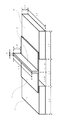
図1に示すように測定試料ガラス板1をガラス製加圧受け台2に設置する。このとき、L1=49mm、L2=40mm、L3=8.4mmである。そして、ステンレス製加圧冶具3(L4=50mm、L5=2.0mm、L6=10mm)をガラス板1の中心線上垂直方向から速度0.5mm/min.の荷重を加え、試料が破壊するまでの最大荷重(P)を測定する。
(3)最大荷重からのガラス強度の算出
ガラス強度は、次式によって算出される。
σ=3PL/2wt2
σ:ガラス強度(N/mm2)
P:試料が破壊したときの最大荷重(N)
L:ガラス製加圧受け台間距離(L1)(49mm)
w:測定試料の幅(L2)(40mm)
t:測定試料の厚み(mm)
【0007】
本発明のガラスの強化方法は、ガラスを研磨液に浸漬し、ガラス表面を150μm以上化学研磨することを特徴とするガラスの強化方法である。ガラス表面の研磨は、ガラス溶解性の研磨液によってガラス表面が化学研磨されることになる。ガラス板を研磨するときには、片面または両面を研磨するのがよい。片面を研磨する場合は、研磨しない面を研磨液に侵されないポリプロピレン製の粘着フィルムやポリ塩化ビニル製の粘着フィルム等でマスキングを施した後に研磨することが例示される。両面を研磨する場合には、ガラス板をそのまま研磨液に浸漬することによって、ガラス表面の研磨をガラス板側面も併せて行うことになるが、必要があれば側面にマスキング等を行って研磨すれば側面の研磨を行わなくて済む。このガラス表面の両面研磨を行う場合、ガラスの厚みを300μmm以上薄くすることで、本発明の強化方法による処理を行っていないガラスに比べて大きく強度が向上し、上記ガラスの強度測定方法で測定すれば、0.05〜2mmの厚みで600〜1000N/mm2の強度を有するガラス板となる。
【0008】
また、本発明の2枚の貼り合わせガラス板を研磨液に浸漬し、ガラス表面を200μm以上化学研磨することを特徴とするガラスの強化方法では、2枚のガラスをシリコン樹脂やエポキシ樹脂等のシーリング剤等で張り合わせたガラス板の強度を向上させることができる。先の研磨方法と同様、ガラス表面の化学研磨は、ガラス溶解性の研磨液によって行われる。ガラス板を研磨するときには、片面の研磨よりも両面を研磨するのが好適である。片面を研磨する場合は、上述と同様のポリプロピレン製の粘着フィルムやポリ塩化ビニル製の粘着フィルム等でマスキングを施した後に研磨することが例示される。両面を研磨する場合には、ガラス板をそのまま研磨液に浸漬し、ガラス板側面も併せて研磨するのが良い。この場合、貼り合わせガラス板の厚みを300μmm以上薄くなるよう研磨することで、当該ガラス板の強度を大きく向上させることが出来る。また、側面を同時に研磨した場合、この研磨に伴ってガラス側面が平坦化することになる。
【0009】
上記ガラスの強化方法及び貼り合わせガラス板の強化方法(以下、「強化方法」)において、ガラスを浸漬した前記研磨液中に気泡を発生させることが好ましい。当該気泡を発生させれば、研磨液中を気泡が移動することに伴い研磨液が攪拌されることになる。研磨液を貯留する槽の底部から気泡を発生させれば、研磨液全体が攪拌されることになる。
【0010】
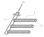
研磨液中への気泡は、例えば、図2に例示する気泡発生装置を使用して発生させることができる。当該気泡発生装置は、空気や窒素等の気体を導入する気体導入管4とこれと垂直に複数連結された多孔質気泡噴出管5からなる。気泡は、外部からポンプによって気体を導入管4を通じて気泡噴出管5に供給することで、噴出管5の無数の気泡噴出孔6から噴出される。気泡噴出管5に変えて、これを図3に例示する多孔質気泡噴出板にしても良い。これらの気泡噴出孔6、7の孔径は、10〜500μmであることが好ましい。この場合、発生する気泡は微細なものとなる。
【0011】
また、研磨液中への気泡の発生は、気体を含む前記研磨液(以下「混合液」)を噴出させることによっても発生させることができる。当該混合液の噴出は、図4に例示されるノズルから噴出させるのが好適である。
【0012】
図4に例示するノズルは、本体部8とこれに螺合する液体導入部9とからなり、本体部8と液体導入部9の間にはオリフィス10が嵌合されたものである。本体部8には、先端側に混合液噴出孔11、当該噴出孔11から本体部8の基端側へ向けて貫通する気液混合部12、この気液混合部12から垂直方向に伸びる気体導入孔13が設けられている。一方、液体導入部9には当該基端部から本体部8へ向けて液体導入孔14が設けられている。そして、オリフィス10には、孔径1〜2mmの2個のオリフィスの孔15がノズル先端部軸方向内側に向けて貫通しており、孔15から噴出する研磨液が気液混合部12内で交わるようにノズル先端方向内向きに孔15が傾斜している。
【0013】
この例示するノズルから気体を含む研磨液を噴出させるには、まず、液体導入孔14に接続した配管を通じて研磨液を液体導入孔14、オリフィスの孔15に次いで気液混合部12に導入することで、研磨液を噴出孔11から噴出させる。当該噴出に伴い空気等の気体が気体導入孔13に接続した配管を通じて気体導入孔13から気液混合部12に導入され、気液混合部12で研磨液と気体が混合した後に噴出孔11から混合液が噴出する。このように混合液を噴出させる方法によれば、使用中に生じるスラッジがノズルの噴出孔11に詰まることなく、ガラスの強化処理をノズル詰まりによるノズル交換なく連続して行うことができる。
【0014】
前記ノズルへの気体の導入が、ノズルへの研磨液の供給によって吸引導入されることが好ましい。この気体の吸引導入は、研磨液をポンプなどの液体圧送装置でノズル内の気液混合部12へ強制的に供給し、気液混合部12内を減圧化させることで可能となる。例えば、本体部12の容積が0.8〜2cm3のノズルを深さ22cmの研磨液中に設置した場合、ノズルからの液吐出量を3〜12L/min.に設定すれば、ノズルに導入する液圧力が0.1〜0.5MPaで気体導入量が3.0〜48.0L/min.であることが好ましい。ノズルからの液吐出量を5L/min.に設定し、ノズルに導入する液圧力が0.3MPaの場合には、気体が9.0L/min.程度の導入量で混合部12に吸引導入される。係るノズルから混合液を噴出させることによって発生する気泡は、前記気泡のみ発生させる方法よりも微細な気泡を発生させることができる。
【0015】
また、当該微細な気泡を含む研磨液の噴出による強化方法でガラス処理を行った場合には、強化処理前から存在するガラス表面傷が研磨に伴い拡大成長することを抑制しつつ、ガラスを強化することができる。
ガラス強度を示すグリフィスの式、
σf=(2Eγs/πc)1/2
σf:ガラスの破壊応力、E:ヤング率、γs:表面エネルギー、c:亀裂の長さ
によれば、ガラスの表面傷の長さが長いほどガラスの破壊応力は小さくなってガラス強度が低下することが示されており、ガラス表面の傷の拡大を抑制することは、ガラス強度の向上につながるものであることが分かっている。つまり、当該微細な気泡を噴出することによるガラス処理によれば、多孔質気泡噴出孔から気泡を噴出させてガラス強度を向上させる方法以上のガラス強度向上が可能となる。
【0016】
なお、気体の吸引導入とは逆にノズルへの気体導入をポンプ等の気体圧送装置を使用して強制的に導入しても良いが、ノズルから噴出する混合液中の気泡は、気体の吸引導入に比べて大きなものとなる。
【0017】
本発明による強化方法で強化できるガラスとしては、ソーダ石灰ガラス、無アルカリガラス、アルカリバリウムガラス、ホウケイ酸ガラス、アルカリホウケイ酸ガラス、アルミノホウケイ酸ガラス、バリウムホウケイ酸ガラス、アルミノケイ酸ガラス、ホウ酸塩ガラス、シリカガラス、鉛ガラス等を組成に有するガラスがある。なお、これらのガラスが、ガラス表面層のイオンを溶融塩中でイオン交換させる化学強化処理や熱処理によって結晶粒子を析出化させる結晶化処理を行っているものであってもよい。化学強化処理は、ガラスをガラス転移点以下のアルカリ溶融塩の中に浸漬し、ガラス表面中のイオンを交換させることにより行われる。アルカリ溶融塩が、硝酸ナトリウム等のナトリウム塩であればガラス中のリチウムイオンをナトリウムイオンに交換することができ、硝酸カリウム等のカリウム塩であればガラス中のナトリウムイオンをカリウムイオンに交換することができる。
【0018】
研磨液には、ガラス溶解性の薬品を組成に含む液体が使用される。好ましい薬品としては、フッ酸、フッ化アンモニウム、フッ化カリウム、フッ化ナトリウム、塩酸、硫酸、リン酸、硝酸、酢酸、コハク酸などのうち1種以上の薬品を含むことであり、フッ酸が2〜25重量%、塩酸が2〜20重量%及び硫酸が2〜20重量%の組成を有する水溶液であることが好適である。研磨液にフッ酸、塩酸及び硫酸以外の薬品を含ませるときには、上記水溶液に対しさらに薬品を1種以上添加することになるが、その場合の添加量は、フッ化アンモニウムが2〜20重量比、フッ化カリウムが1〜5重量比、フッ化ナトリウムが1〜5重量比、リン酸が2〜20重量比、硝酸が1〜5重量比、酢酸が0.1〜1重量比、コハク酸が0.1〜1重量比となるのが好適である。その他、研磨処理によって生じたスラッジがガラス表面に付着することを防止するため、陰イオン系界面活性剤及び両性界面活性剤から選択される1種以上を0.01〜0.1重量比さらに添加しても良い。
【0019】
強化方法におけるガラスの研磨液への浸漬時間及び温度はガラスを構成するガラスの組成、大きさ及び厚みによって適宜変更されることになる。平坦性の優れたガラス板を製造する場合、ガラス表面を研磨する速度は、0.5〜10μm/min.であることが好ましい。10μm/min.を超える研磨速度であれば、表面にウネリが生じやすく、平坦性の優れたガラス板を製造することが困難になる。一方、研磨速度が0.5μm/min.を下回ると、生産効率の点から好ましくない。
【0020】
ガラス板の浸漬は、研磨液中に気泡を発生させていない場合は、任意にガラスを浸漬することによって行われる。一方で、研磨液中に気泡を発生させている場合、ガラス板に対して気泡が平行に流れるようにするか気泡が垂直方向から衝突するように浸漬する他、研磨液液面に対して任意の方向にガラス板を浸漬してガラスの強化を行うことができるが、ガラス板を研磨液の液面に対して垂直方向に保持して浸漬させると気泡がガラス板に対して平行に流れるようになって、研磨液中における気泡の流れの阻害をできるだけ避けて研磨液の流動を均一化することができるので、当該浸漬方法が好ましいと言える。
【0021】
【実施の態様】
以下に本発明の実施態様を示す。なお、本発明の実施態様は以下の実施態様に限定されるものではない。
【0022】
本発明の0.05〜2mmの厚みで、600〜1000N/mm2の強度を有するガラス板を得るには、例えば、上述したガラス板を研磨液に浸漬しガラス板表面を150μm以上化学研磨する方法や前記研磨液中に気泡を発生させてガラス板を研磨する方法がある。このような方法で、本発明による高強度ガラスを得ることができる。なお、研磨液中に気泡を発生させる方法は、上述した、多孔質気泡噴出孔に気体を供給することによって発生させる方法や気体を含む前記研磨液を噴出させることによって発生させる方法等がある。
【0023】
また、本発明の高強度ガラスを得るためのガラス素材としては、ソーダ石灰ガラス、無アルカリガラス、アルカリバリウムガラス、ホウケイ酸ガラス、アルカリホウケイ酸ガラス、アルミノホウケイ酸ガラス、バリウムホウケイ酸ガラス、アルミノケイ酸ガラス、ホウ酸塩ガラス、シリカガラス、鉛ガラス等を組成に有するガラス板がある。ガラスが結晶化ガラスであっても良い。また、アルカリガラスの場合は、イオン交換による化学強化処理が行われていても良い。なお、結晶化ガラスは、熱処理によって結晶粒子を析出化させる結晶化処理によって形成される。また、化学強化処理は、ガラスをガラス転移点以下のアルカリ溶融塩の中に浸漬し、ガラス表面中のイオンを交換させることにより行われる。アルカリ溶融塩が、硝酸ナトリウム等のナトリウム塩であればガラス中のリチウムイオンをナトリウムイオンに交換することができ、硝酸カリウム等のカリウム塩であればガラス中のナトリウムイオンをカリウムイオンに交換することができる。
【0024】
高強度ガラスを得るために使用する研磨液には、フッ酸、フッ化アンモニウム、フッ化カリウム、フッ化ナトリウム、塩酸、硫酸、リン酸、硝酸、酢酸、コハク酸などのうち1種以上の薬品を含む水溶液が使用される。中でも、フッ酸が2〜25重量%、塩酸が2〜20重量%及び硫酸が2〜20重量%の組成を有する水溶液であることが好適である。研磨液にフッ酸、塩酸及び硫酸以外の薬品を含ませるときには、フッ化アンモニウム、フッ化カリウム、フッ化ナトリウム、リン酸、硝酸、酢酸、コハク酸の内から選択される薬品を1種以上添加することが好適であり、この場合の添加量は、フッ化アンモニウムが2〜20重量比、フッ化カリウムが1〜5重量比、フッ化ナトリウムが1〜5重量比、リン酸が2〜20重量比、硝酸が1〜5重量比、酢酸が0.1〜1重量比、コハク酸が0.1〜1重量比となるように添加するのが好適である。その他、陰イオン系界面活性剤及び両性界面活性剤から選択される1種以上を0.01〜0.1重量比さらに添加しても良い。
【0025】
高強度ガラスを得るためのガラス板の研磨液への浸漬時間及び温度はガラスを構成するガラスの組成、大きさ及び厚みによって適宜変更されることになる。例えば、400mm×500mm×0.7mmの無アルカリガラス板の場合は、40℃の研磨液に60分間当該ガラス板を浸漬して化学研磨することで、高強度ガラスを得ることができる。
【0026】
以下に本発明の具体例を実施例に基づき示す。
【実施例1】
縦40mm、横60mm、厚み0.7mmの無アルカリガラス板を、研磨液貯留槽底部に設置された多孔質気泡噴出孔から微細な気泡が発生している研磨液に浸漬し、ガラス表面を150μm(ガラス板厚が300μm薄くなるまで)研磨した。その後、ガラスが破壊するときの最大荷重を測定し、ガラス強度を算出した。一方、ガラス強度の比較のため、当該ガラス強化処理を行っていないガラスについても、破壊最大荷重の測定及びガラス強度の算出を行った(比較例1)。
【0027】
なお、研磨液には、フッ酸5重量%、塩酸10重量%、硝酸5重量%を組成とする40℃の水溶液を用いた。また、ガラス板の研磨液への浸漬は、多孔質気泡噴出孔の上方20cmの位置に化学加工液の液面に対してガラス板を垂直に保持し、60分間浸漬した。この研磨液及びガラス板の浸漬条件は、以下の実施例において全て同じ条件である。
【0028】
【実施例2】
縦40mm、横60mm、厚み1.1mmの無アルカリガラス板を、実施例1と同じ条件で、ガラス表面を300μm(ガラス板厚が600μm薄くなるまで)研磨して、破壊するまでの最大荷重を測定した。また、実施例1と同じく、当該ガラスの強化処理を行っていないガラス板の破壊最大荷重測定及びガラス強度の算出を行った(比較例2)。
【0029】
上述した最大荷重の測定値及びガラス強度は、以下の表1の通りであった。
【表1】

表1の結果からわかるように、実施例1及び2のガラス板は、本発明の0.05〜2mmの厚みで、600〜1000N/mm2の強度を有するガラス板であることが確認された。また、本発明のガラスを研磨液に浸漬し、ガラス表面を150μm以上化学研磨するガラスの強化方法を使用することによって得られたガラス板は、ガラスの表面が強化されていることが確認された。
【0031】
無アルカリガラス板2枚をシリコン樹脂で貼り合わせたガラス板を研磨液に浸漬し、実施例1と同じ方法で、ガラス表面を300μm(貼り合わせガラス板の厚みが600μm薄くなるまで)化学研磨した結果、当該ガラス板の強度が向上していることが確認された。つまり、ガラス表面を200μm以上研磨することで、ガラス強度が向上することが確認された。
【0032】
さらに、実施例1の気泡発生方法に変えて、図4に示すノズルを使用して混合液を噴出させることで気泡発生を行った。この条件で実施例1及び2と同じガラス板を強化した。そして、得られたガラス板は対応する実施例のガラス板よりも高強度であることが確認された。なお、強化処理後、ノズルの噴出孔にスラッジ詰まり、析出がないことが目視で確認された。
【0033】
以上のように、本発明の高強度ガラスであることが確認された。また、本発明の強化方法によれば、ガラス強度が向上することが確認された。
【0034】
【発明の効果】
本発明によるガラス板は、上述のように従来にないガラス強度を有するので、高いガラス強度が必要とするところに使用することが可能である。また、本発明のガラスの強化方法でガラスの強化処理を行うことで、ガラス強度が著しく向上する。
【図面の簡単な説明】
【図1】ガラス強度測定方法を図示したものである。
【図2】多孔質気泡噴出孔を有する気泡発生装置の一例である。
【図3】多孔質気泡噴出板の一例である。
【図4】混合液を噴出させるノズルの一例である。[0001]
TECHNICAL FIELD OF THE INVENTION
The present invention relates to a high-strength glass used for a display of an electronic device, a substrate of a magnetic disk storage medium, a window glass, a glass product for cooking, a furniture article, and the like, and a method of strengthening the glass.
[0002]
[Prior art]
In recent years, with the reduction in the weight of electronic devices and the like, there is a demand for reducing the weight of glass used for these devices. To meet this demand, the thickness of the glass must be reduced, but this also causes a reduction in the glass strength. Therefore, it is expected that a high-strength glass and a method for improving the strength of the glass are provided.
[0003]
As the glass with improved strength, there is a glass described in
[Non-patent document 1]
Ed., Surface Technology Association, “Surface Technology Handbook”, First Edition, Nikkan Kogyo Shimbun, Feb. 27, 1998, p. 1569
[0004]
[Problems to be solved by the invention]
However, even the glass obtained by the method described in Non-Patent
[0005]
[Means for Solving the Problems]
The glass plate of the present invention is a glass plate having a thickness of 0.05 to 2 mm and a strength of 600 to 1000 N / mm 2 . The glass strength is derived from the following measuring method and calculating method.
[0006]
(1) A glass plate having a size of 40 mm in length and 60 mm in width is used. Before measuring the breaking load described below, the thickness of the sample is measured.
(2) Method of Measuring Fracture Stress of Glass Plate As shown in FIG. 1, a measurement
(3) Calculation of glass strength from maximum load Glass strength is calculated by the following equation.
σ = 3PL / 2wt 2
σ: glass strength (N / mm 2 )
P: Maximum load when the sample breaks (N)
L: distance between glass pressure receiving pedestals (L1) (49 mm)
w: width of the measurement sample (L2) (40 mm)
t: thickness of the measurement sample (mm)
[0007]
The method for strengthening glass of the present invention is a method for strengthening glass, characterized by immersing glass in a polishing solution and chemically polishing the glass surface to 150 μm or more. In polishing the glass surface, the glass surface is chemically polished by a glass-soluble polishing liquid. When polishing a glass plate, it is preferable to polish one or both sides. When one side is polished, the non-polished side is polished after masking with a polypropylene adhesive film or a polyvinyl chloride adhesive film which is not affected by the polishing liquid. When polishing both surfaces, the glass surface is polished as it is by immersing the glass plate in the polishing solution, so that the glass surface is also polished on the side of the glass plate if necessary. This eliminates the need for side polishing. When performing double-side polishing of the glass surface, by reducing the thickness of the glass to 300 μmm or more, the strength is greatly improved as compared with the glass that has not been treated by the strengthening method of the present invention. Then, a glass plate having a thickness of 0.05 to 2 mm and a strength of 600 to 1000 N / mm 2 is obtained.
[0008]
Further, in the glass strengthening method according to the present invention, in which the two bonded glass plates are immersed in a polishing solution and the glass surface is chemically polished to 200 μm or more, the two glasses are made of a silicone resin or an epoxy resin. The strength of the glass plate bonded with a sealing agent or the like can be improved. As in the previous polishing method, the chemical polishing of the glass surface is performed by a glass-soluble polishing liquid. When polishing a glass plate, it is preferable to polish both surfaces rather than one surface. When one side is polished, the polishing may be performed after masking with the same adhesive film made of polypropylene or polyvinyl chloride as described above. When both sides are polished, it is preferable to immerse the glass plate as it is in the polishing liquid and polisher the side surfaces of the glass plate together. In this case, by polishing so that the thickness of the laminated glass plate is reduced to 300 μmm or more, the strength of the glass plate can be greatly improved. When the side surfaces are polished at the same time, the glass side surfaces are flattened with the polishing.
[0009]
In the method for strengthening glass and the method for strengthening a laminated glass plate (hereinafter referred to as “strengthening method”), it is preferable to generate bubbles in the polishing liquid in which glass is immersed. When the bubbles are generated, the polishing liquid is stirred as the bubbles move in the polishing liquid. If bubbles are generated from the bottom of the tank storing the polishing liquid, the entire polishing liquid is stirred.
[0010]
The bubbles in the polishing liquid can be generated, for example, using a bubble generator illustrated in FIG. The bubble generator includes a gas inlet pipe 4 for introducing a gas such as air or nitrogen, and a plurality of porous
[0011]
The generation of bubbles in the polishing liquid can also be generated by ejecting the polishing liquid containing a gas (hereinafter, “mixture liquid”). It is preferable that the mixed liquid is ejected from a nozzle illustrated in FIG.
[0012]
The nozzle illustrated in FIG. 4 includes a main body 8 and a liquid introduction section 9 screwed to the main body 8, and an
[0013]
In order to eject a polishing liquid containing gas from this exemplified nozzle, first, the polishing liquid is introduced into the gas introduction section 14 through the pipe connected to the liquid introduction hole 14, and then into the gas-liquid mixing section 12. Then, the polishing liquid is ejected from the ejection holes 11. A gas such as air is introduced into the gas-liquid mixing unit 12 from the gas introduction hole 13 through a pipe connected to the gas introduction hole 13 with the ejection, and after the polishing liquid and the gas are mixed in the gas-liquid mixing unit 12, the gas is ejected from the ejection hole 11. The mixture gushes. According to the method of ejecting the mixed liquid as described above, the glass strengthening process can be performed continuously without replacing the nozzle due to nozzle clogging without sludge generated during use clogging the ejection hole 11 of the nozzle.
[0014]
It is preferable that the gas is introduced into the nozzle by suction by supplying a polishing liquid to the nozzle. The suction of the gas can be achieved by forcibly supplying the polishing liquid to the gas-liquid mixing unit 12 in the nozzle by a liquid pressure feeding device such as a pump, thereby reducing the pressure inside the gas-liquid mixing unit 12. For example, when a nozzle having a volume of the main body 12 of 0.8 to 2 cm 3 is installed in a polishing liquid having a depth of 22 cm, the liquid discharge rate from the nozzle is 3 to 12 L / min. , The liquid pressure introduced into the nozzle is 0.1 to 0.5 MPa and the gas introduction amount is 3.0 to 48.0 L / min. It is preferable that The amount of liquid discharged from the nozzle is 5 L / min. When the liquid pressure introduced into the nozzle is 0.3 MPa, the gas is 9.0 L / min. It is sucked and introduced into the mixing unit 12 with a small amount of introduction. The bubbles generated by ejecting the mixed liquid from the nozzle can generate finer bubbles than the method of generating only the bubbles.
[0015]
Further, when the glass treatment is performed by the strengthening method by jetting out the polishing liquid containing the fine bubbles, the glass surface is strengthened while suppressing the glass surface scratches existing before the strengthening treatment from expanding and growing along with the polishing. can do.
Griffith's formula indicating glass strength,
σf = (2Eγ s / πc) 1/2
According to σf: glass breaking stress, E: Young's modulus, γ s : surface energy, c: crack length, the longer the glass surface flaw length, the smaller the glass breaking stress and the lower the glass strength. It has been shown that suppressing the expansion of scratches on the glass surface leads to an improvement in glass strength. That is, according to the glass treatment by ejecting the fine bubbles, it is possible to improve the glass strength more than the method of improving the glass strength by ejecting the bubbles from the porous bubble ejection holes.
[0016]
It should be noted that gas introduction into the nozzle may be forcibly introduced using a gas pumping device such as a pump, contrary to the gas suction introduction. However, bubbles in the mixed liquid ejected from the nozzle cause gas suction. It will be bigger than the introduction.
[0017]
Glasses that can be strengthened by the tempering method according to the present invention include soda-lime glass, alkali-free glass, alkali barium glass, borosilicate glass, alkali borosilicate glass, aluminoborosilicate glass, barium borosilicate glass, aluminosilicate glass, and borate There is glass having a composition of glass, silica glass, lead glass and the like. Note that these glasses may have been subjected to a chemical strengthening treatment for exchanging ions in the glass surface layer in a molten salt or a crystallization treatment for precipitating crystal particles by heat treatment. The chemical strengthening treatment is performed by immersing the glass in an alkali molten salt having a glass transition temperature or lower to exchange ions in the glass surface. If the alkali molten salt is a sodium salt such as sodium nitrate, lithium ions in the glass can be exchanged for sodium ions, and if a potassium salt such as potassium nitrate, the sodium ions in the glass can be exchanged for potassium ions. it can.
[0018]
As the polishing liquid, a liquid containing a glass-soluble chemical in its composition is used. Preferred chemicals include one or more of hydrofluoric acid, ammonium fluoride, potassium fluoride, sodium fluoride, hydrochloric acid, sulfuric acid, phosphoric acid, nitric acid, acetic acid, succinic acid, and the like. It is preferable that the aqueous solution has a composition of 2 to 25% by weight, 2 to 20% by weight of hydrochloric acid, and 2 to 20% by weight of sulfuric acid. When chemicals other than hydrofluoric acid, hydrochloric acid, and sulfuric acid are included in the polishing liquid, one or more chemicals are further added to the aqueous solution. In this case, the amount of ammonium fluoride is 2 to 20% by weight. , Potassium fluoride 1-5 weight ratio, sodium fluoride 1-5 weight ratio, phosphoric acid 2-20 weight ratio, nitric acid 1-5 weight ratio, acetic acid 0.1-1 weight ratio, succinic acid Is preferably 0.1 to 1 weight ratio. In addition, in order to prevent sludge generated by the polishing treatment from adhering to the glass surface, one or more selected from anionic surfactants and amphoteric surfactants are further added in a weight ratio of 0.01 to 0.1. You may.
[0019]
The time and temperature at which the glass is immersed in the polishing liquid in the tempering method are appropriately changed depending on the composition, size and thickness of the glass constituting the glass. When manufacturing a glass plate having excellent flatness, the polishing rate of the glass surface is 0.5 to 10 μm / min. It is preferable that 10 μm / min. If the polishing rate exceeds, undulation is likely to occur on the surface, and it becomes difficult to produce a glass plate having excellent flatness. On the other hand, when the polishing rate is 0.5 μm / min. If the ratio is lower than the above, it is not preferable in terms of production efficiency.
[0020]
If no bubbles are generated in the polishing liquid, the glass plate is immersed by arbitrarily immersing the glass. On the other hand, when bubbles are generated in the polishing liquid, the bubbles are allowed to flow in parallel to the glass plate or immersed so that the bubbles collide from the vertical direction. The glass can be strengthened by immersing the glass plate in the direction of, but when the glass plate is held and immersed in the direction perpendicular to the surface of the polishing liquid, air bubbles flow parallel to the glass plate. Thus, the flow of the polishing liquid can be made uniform while preventing the flow of air bubbles in the polishing liquid as much as possible, so that the immersion method is preferable.
[0021]
Embodiment
Hereinafter, embodiments of the present invention will be described. The embodiments of the present invention are not limited to the following embodiments.
[0022]
In order to obtain a glass plate having a thickness of 0.05 to 2 mm and a strength of 600 to 1000 N / mm 2 according to the present invention, for example, the above-described glass plate is immersed in a polishing liquid and the surface of the glass plate is chemically polished to 150 μm or more. There is a method and a method of polishing a glass plate by generating bubbles in the polishing liquid. By such a method, the high-strength glass according to the present invention can be obtained. The method of generating bubbles in the polishing liquid includes the above-described method of generating gas by supplying a gas to the porous bubble ejection hole and the method of generating gas by discharging the polishing liquid containing gas.
[0023]
The glass material for obtaining the high-strength glass of the present invention includes soda-lime glass, alkali-free glass, alkali barium glass, borosilicate glass, alkali borosilicate glass, aluminoborosilicate glass, barium borosilicate glass, and aluminosilicate. There is a glass plate having a composition of glass, borate glass, silica glass, lead glass or the like. The glass may be crystallized glass. In the case of alkali glass, a chemical strengthening treatment by ion exchange may be performed. Note that the crystallized glass is formed by a crystallization process of precipitating crystal particles by heat treatment. In addition, the chemical strengthening treatment is performed by immersing the glass in an alkali molten salt having a glass transition point or lower to exchange ions in the glass surface. If the alkali molten salt is a sodium salt such as sodium nitrate, lithium ions in the glass can be exchanged for sodium ions, and if a potassium salt such as potassium nitrate, the sodium ions in the glass can be exchanged for potassium ions. it can.
[0024]
The polishing liquid used to obtain high-strength glass includes one or more chemicals such as hydrofluoric acid, ammonium fluoride, potassium fluoride, sodium fluoride, hydrochloric acid, sulfuric acid, phosphoric acid, nitric acid, acetic acid, and succinic acid. An aqueous solution containing is used. Among them, an aqueous solution having a composition of 2 to 25% by weight of hydrofluoric acid, 2 to 20% by weight of hydrochloric acid and 2 to 20% by weight of sulfuric acid is preferable. When chemicals other than hydrofluoric acid, hydrochloric acid and sulfuric acid are included in the polishing liquid, one or more chemicals selected from ammonium fluoride, potassium fluoride, sodium fluoride, phosphoric acid, nitric acid, acetic acid and succinic acid are added. In this case, the addition amount is preferably 2 to 20 weight ratio of ammonium fluoride, 1 to 5 weight ratio of potassium fluoride, 1 to 5 weight ratio of sodium fluoride, and 2 to 20 weight ratio of phosphoric acid. It is preferable to add so that the weight ratio, nitric acid is 1 to 5 weight ratio, acetic acid is 0.1 to 1 weight ratio, and succinic acid is 0.1 to 1 weight ratio. In addition, one or more selected from anionic surfactants and amphoteric surfactants may be further added in a weight ratio of 0.01 to 0.1.
[0025]
The time and temperature at which the glass plate is immersed in the polishing liquid to obtain high-strength glass will be appropriately changed depending on the composition, size and thickness of the glass constituting the glass. For example, in the case of a 400 mm × 500 mm × 0.7 mm non-alkali glass plate, a high strength glass can be obtained by immersing the glass plate in a polishing solution at 40 ° C. for 60 minutes and chemically polishing the glass plate.
[0026]
Hereinafter, specific examples of the present invention will be described based on examples.
An alkali-free glass plate having a length of 40 mm, a width of 60 mm, and a thickness of 0.7 mm is immersed in a polishing liquid in which fine bubbles are generated from a porous bubble ejection hole installed at the bottom of the polishing liquid storage tank, and the glass surface is 150 μm thick. Polishing was performed (until the glass plate thickness was reduced by 300 μm). Thereafter, the maximum load at which the glass was broken was measured, and the glass strength was calculated. On the other hand, for comparison of the glass strength, the measurement of the maximum breaking load and the calculation of the glass strength were also performed on the glass not subjected to the glass strengthening treatment (Comparative Example 1).
[0027]
As the polishing liquid, an aqueous solution of 40 ° C. having a composition of 5% by weight of hydrofluoric acid, 10% by weight of hydrochloric acid and 5% by weight of nitric acid was used. The glass plate was immersed in the polishing liquid by holding the glass plate perpendicular to the surface of the chemical processing liquid at a position 20 cm above the porous bubble ejection hole and immersing the glass plate for 60 minutes. The conditions for dipping the polishing liquid and the glass plate are the same in all of the following examples.
[0028]
A non-alkali glass plate having a length of 40 mm, a width of 60 mm and a thickness of 1.1 mm was polished on the glass surface under the same conditions as in Example 1 by 300 μm (until the thickness of the glass plate became 600 μm thinner), and the maximum load before breaking was measured. It was measured. Further, as in Example 1, the maximum breaking load of the glass sheet not subjected to the tempering treatment and the calculation of the glass strength were performed (Comparative Example 2).
[0029]
The above-described measured values of the maximum load and the glass strength were as shown in Table 1 below.
[Table 1]
As can be seen from the results in Table 1, it was confirmed that the glass plates of Examples 1 and 2 were glass plates having a thickness of 0.05 to 2 mm and a strength of 600 to 1000 N / mm 2 according to the present invention. . Further, it was confirmed that the glass plate obtained by immersing the glass of the present invention in a polishing liquid and using a glass strengthening method of chemically polishing the glass surface by 150 μm or more had a strengthened glass surface. .
[0031]
A glass plate obtained by laminating two alkali-free glass plates with a silicone resin was immersed in a polishing solution, and the glass surface was chemically polished by the same method as in Example 1 to 300 μm (until the thickness of the laminated glass plate became 600 μm thinner). As a result, it was confirmed that the strength of the glass plate was improved. That is, it was confirmed that the glass strength was improved by polishing the glass surface by 200 μm or more.
[0032]
Further, instead of the bubble generation method of Example 1, bubbles were generated by ejecting the mixture using the nozzle shown in FIG. Under these conditions, the same glass plate as in Examples 1 and 2 was strengthened. And it was confirmed that the obtained glass plate had higher strength than the glass plate of the corresponding example. After the strengthening treatment, it was visually confirmed that there was no sludge clogging or precipitation in the ejection holes of the nozzle.
[0033]
As described above, it was confirmed that the glass was the high-strength glass of the present invention. Further, it was confirmed that the glass strength was improved by the strengthening method of the present invention.
[0034]
【The invention's effect】
As described above, the glass plate according to the present invention has an unprecedented glass strength, and thus can be used where high glass strength is required. Further, by performing the glass strengthening treatment by the glass strengthening method of the present invention, the glass strength is significantly improved.
[Brief description of the drawings]
FIG. 1 illustrates a glass strength measuring method.
FIG. 2 is an example of a bubble generator having a porous bubble ejection hole.
FIG. 3 is an example of a porous bubble jet plate.
FIG. 4 is an example of a nozzle for ejecting a mixed liquid.
Claims (6)
Priority Applications (1)
| Application Number | Priority Date | Filing Date | Title |
|---|---|---|---|
| JP2003140564A JP2004339036A (en) | 2003-05-19 | 2003-05-19 | High-strength glass plate and method for toughening glass |
Applications Claiming Priority (1)
| Application Number | Priority Date | Filing Date | Title |
|---|---|---|---|
| JP2003140564A JP2004339036A (en) | 2003-05-19 | 2003-05-19 | High-strength glass plate and method for toughening glass |
Publications (2)
| Publication Number | Publication Date |
|---|---|
| JP2004339036A true JP2004339036A (en) | 2004-12-02 |
| JP2004339036A5 JP2004339036A5 (en) | 2006-06-01 |
Family
ID=33529258
Family Applications (1)
| Application Number | Title | Priority Date | Filing Date |
|---|---|---|---|
| JP2003140564A Pending JP2004339036A (en) | 2003-05-19 | 2003-05-19 | High-strength glass plate and method for toughening glass |
Country Status (1)
| Country | Link |
|---|---|
| JP (1) | JP2004339036A (en) |
Cited By (9)
| Publication number | Priority date | Publication date | Assignee | Title |
|---|---|---|---|---|
| JP2006315929A (en) * | 2005-05-16 | 2006-11-24 | Nishiyama Stainless Chem Kk | Method of polishing glass surface |
| JP2008208007A (en) * | 2007-02-28 | 2008-09-11 | Shinetsu Quartz Prod Co Ltd | Etching method of quartz glass member |
| JP2008208008A (en) * | 2007-02-28 | 2008-09-11 | Shinetsu Quartz Prod Co Ltd | Etching method of quartz glass member |
| KR100937262B1 (en) | 2009-08-31 | 2010-01-18 | 이기송 | Manufacturing method of strengthed glass for touch panel |
| JP2011236100A (en) * | 2010-05-13 | 2011-11-24 | Hitachi Displays Ltd | Chemical polishing solution for glass substrate, and method for polishing glass substrate using the same |
| KR101333289B1 (en) | 2013-07-12 | 2013-11-27 | 주식회사 도우인시스 | Chemical furnace apparatus for uniform tempered glass manufacturing |
| KR101445357B1 (en) | 2014-07-28 | 2014-10-02 | 주식회사 도우인시스 | Chemical Strengthening Furnace with Up and Down Movable Bubble Productor |
| KR101478686B1 (en) | 2007-05-14 | 2015-01-02 | 니폰 덴키 가라스 가부시키가이샤 | Laminated glass for window and glass window member |
| KR101527186B1 (en) * | 2013-12-03 | 2015-06-09 | 선문대학교 산학협력단 | Homogenization apparatus and method of potassium nitrate solution for glass chemical strengthening |
-
2003
- 2003-05-19 JP JP2003140564A patent/JP2004339036A/en active Pending
Cited By (10)
| Publication number | Priority date | Publication date | Assignee | Title |
|---|---|---|---|---|
| JP2006315929A (en) * | 2005-05-16 | 2006-11-24 | Nishiyama Stainless Chem Kk | Method of polishing glass surface |
| JP2008208007A (en) * | 2007-02-28 | 2008-09-11 | Shinetsu Quartz Prod Co Ltd | Etching method of quartz glass member |
| JP2008208008A (en) * | 2007-02-28 | 2008-09-11 | Shinetsu Quartz Prod Co Ltd | Etching method of quartz glass member |
| KR101478686B1 (en) | 2007-05-14 | 2015-01-02 | 니폰 덴키 가라스 가부시키가이샤 | Laminated glass for window and glass window member |
| KR100937262B1 (en) | 2009-08-31 | 2010-01-18 | 이기송 | Manufacturing method of strengthed glass for touch panel |
| JP2011236100A (en) * | 2010-05-13 | 2011-11-24 | Hitachi Displays Ltd | Chemical polishing solution for glass substrate, and method for polishing glass substrate using the same |
| KR101333289B1 (en) | 2013-07-12 | 2013-11-27 | 주식회사 도우인시스 | Chemical furnace apparatus for uniform tempered glass manufacturing |
| WO2015005544A1 (en) * | 2013-07-12 | 2015-01-15 | 주식회사 도우인시스 | Chemical tempering furnace apparatus for manufacturing uniform tempered glass |
| KR101527186B1 (en) * | 2013-12-03 | 2015-06-09 | 선문대학교 산학협력단 | Homogenization apparatus and method of potassium nitrate solution for glass chemical strengthening |
| KR101445357B1 (en) | 2014-07-28 | 2014-10-02 | 주식회사 도우인시스 | Chemical Strengthening Furnace with Up and Down Movable Bubble Productor |
Similar Documents
| Publication | Publication Date | Title |
|---|---|---|
| TWI675015B (en) | Glass-based articles including a metal oxide concentration gradient | |
| CN113582553B (en) | Processing technology of ultrathin glass cover plate | |
| KR101346930B1 (en) | Glass plate and method for manufacturing glass plate | |
| US20120052302A1 (en) | Method of strengthening edge of glass article | |
| TW201006777A (en) | Method for etching alkali-free glass substrate and display device | |
| JP2004339036A (en) | High-strength glass plate and method for toughening glass | |
| JP2016040211A (en) | Method for producing antiglare glass | |
| CN107848870A (en) | Show the glassware of improved rupture performance | |
| CN109095789B (en) | Method for producing chemically strengthened glass | |
| JP2012218995A (en) | Method for manufacturing tempered glass plate and cover glass, and cover glass | |
| TWI263079B (en) | Chemical polishing method for liquid crystal glass substrate and chemical polishing apparatus | |
| CN105800948A (en) | Glass reinforcing method and reinforced glass | |
| CN103253868A (en) | Liquid crystal display screen thinning pretreatment liquid and liquid crystal display screen thinning method | |
| CN102513940A (en) | Method for producing glass with low reflectance and high transparency for screen panel | |
| JPWO2018062141A1 (en) | Method of producing chemically strengthened glass | |
| CN106854037B (en) | A kind of silicate product and its intensifying method | |
| WO2016117479A1 (en) | Glass substrate production method | |
| KR20120038079A (en) | Manufacturing method for tempered glass and tempered glass thereof | |
| JP2008029920A (en) | Liquid discharge nozzle and method of manufacturing liquid discharge nozzle | |
| KR20130037013A (en) | Tempered glass and method for manufacturing the same | |
| JP2012250302A (en) | Nano-bubble circulation type polishing device | |
| JP2005008423A (en) | Method and apparatus for chemically processing glass | |
| JP2006315929A (en) | Method of polishing glass surface | |
| CN107188398A (en) | The manufacture method of chemically reinforced glass | |
| JP5533374B2 (en) | Manufacturing method of glass substrate for magnetic disk. |
Legal Events
| Date | Code | Title | Description |
|---|---|---|---|
| A521 | Written amendment |
Effective date: 20060412 Free format text: JAPANESE INTERMEDIATE CODE: A523 |
|
| A621 | Written request for application examination |
Effective date: 20060412 Free format text: JAPANESE INTERMEDIATE CODE: A621 |
|
| A977 | Report on retrieval |
Free format text: JAPANESE INTERMEDIATE CODE: A971007 Effective date: 20080828 |
|
| A131 | Notification of reasons for refusal |
Effective date: 20080909 Free format text: JAPANESE INTERMEDIATE CODE: A131 |
|
| A521 | Written amendment |
Free format text: JAPANESE INTERMEDIATE CODE: A523 Effective date: 20081023 |
|
| A131 | Notification of reasons for refusal |
Effective date: 20081202 Free format text: JAPANESE INTERMEDIATE CODE: A131 |
|
| A521 | Written amendment |
Free format text: JAPANESE INTERMEDIATE CODE: A523 Effective date: 20090129 |
|
| A02 | Decision of refusal |
Effective date: 20090303 Free format text: JAPANESE INTERMEDIATE CODE: A02 |