JP2004241024A - Disk drive - Google Patents
Disk drive Download PDFInfo
- Publication number
- JP2004241024A JP2004241024A JP2003027291A JP2003027291A JP2004241024A JP 2004241024 A JP2004241024 A JP 2004241024A JP 2003027291 A JP2003027291 A JP 2003027291A JP 2003027291 A JP2003027291 A JP 2003027291A JP 2004241024 A JP2004241024 A JP 2004241024A
- Authority
- JP
- Japan
- Prior art keywords
- disk
- opening
- storage chamber
- outside air
- disk device
- Prior art date
- Legal status (The legal status is an assumption and is not a legal conclusion. Google has not performed a legal analysis and makes no representation as to the accuracy of the status listed.)
- Withdrawn
Links
Images


Abstract
Description
【0001】
【発明の属する技術分野】
本発明は、筐体内にディスクの駆動機構等を配置したディスク装置に関する。
【0002】
【従来の技術】
従来、筐体内にディスクの駆動機構等を配置したディスク装置が知られている。このようなディスク装置では、筐体内には、内部隔壁を隔てて信号処理基板などが配置され、この信号処理基板には、各回路が実装されている。したがって、この信号処理基板からは、消費電力に相当する発熱が生じる。また、ディスク装置の小型化が進むことから、スペース的にも消費電力の面からも、上記発熱を防止するためのファンなどの強制冷却装置を実装するようにした技術も行われている。
【0003】
このような従来の問題点を解決する技術として特許文献1記載の技術が提案されている。図10は、このような従来のディスク装置を説明するための図である。図10に示すように、従来のディスク装置は、筐体110の一方の外側壁110Aのディスク室114側に排気用の開口部104が形成されており、筐体110の他方の外側壁110Bの基板室側に吸気用の開口部106が形成されている。また、基板室とディスク室114の間の内部隔壁112には、OP142を配置するための開口部112Aが形成されている。そして、光ディスクの高速回転によって発生した気流により、吸気用の開口部106から吸い込まれた空気が基板室側から穴112Aを通ってディスク室114を通り、排気用の開口部104に排出される。すなわち、筐体110内に外気の通風路を形成し、光ディスクの高速回転によって冷気を流通させることにより、冷却用ファンなどを設けることなく内部冷却を行うことが可能となるというものである。
【0004】
【特許文献1】
特開2001−155479号公報
【発明が解決しようとする課題】
しかしながら、従来のディスク装置は、排気用の開口部104と、吸気用の開口部106と、開口部112Aとを形成して、筐体110内に外気の通風路を形成し、光ディスクの高速回転によって冷気を流通させるようにし内部冷却するようにして、外部の外部の空気をディスク収納室に運ぶようにしているが、この従来のディスク装置の冷却方法では、外部の空気を効果的にディスク収納室に運ぶことができない。このため、冷却効率が悪く、ディスク装置内部の温度上昇を抑制することができないという問題がある。また、メカ部の温度上昇により、光ピックアップの寿命に悪影響を与えてしまう。また、効果的な気流が発生しないので塵埃の堆積にとっても好ましくない。
【0005】
そこで、本発明は上記従来技術の問題点を解決し、ディスク装置内部の温度上昇を抑制することができるディスク装置を提供することを目的とする。
【0006】
【課題を解決するための手段】
上記課題を解決するために、請求項1記載のディスク装置は、ディスクを駆動するディスク駆動機構と、筐体と、該筐体とともに前記ディスク駆動機構を収容するディスク収容室を形成し、該ディスク収納室の下部に設けられた隔壁と、を備えたディスク装置において、前記筐体の上面に、前記ディスク収納室内に外気を吸気するための第1の開口部を設けたことを特徴とする。
【0007】
請求項1記載の発明によれば、筐体の上面に、ディスク収納室内に外気を吸気するための第1の開口部を設けたので、ディスクが回転することにより、ディスク収納室内におけるディスクの回転中心付近の気圧が下がるため、外気は、この第1の開口部を介して、ディスク収納室内に吸気される。これにより、ディスク装置内部の温度上昇を抑制することができる。
【0008】
また、請求項2記載のディスク装置は、請求項1記載のディスク装置において、更に、前記筐体の側面に、前記ディスク収納室内に外気を吸気し又は前記ディスク収納室内の空気を外部に排出するための第2の開口部を設けたことを特徴とする。
【0009】
請求項2記載の発明によれば、筐体の側面に、ディスク収納室内の空気を外部に排出するための第2の開口部を設けたので、第1の開口部からディスク収納室内に吸気された空気は、この第2の開口部を通じてディスク収納室内の外部に効率よく排出される。これにより、第1の開口部のみを設けた場合よりも整流効果が望めるため、さらに、ディスク装置内部の温度上昇を抑制することができるとともに、外気に含まれる塵埃がディスク装置内に堆積するのを防止することもできる。また、筐体の側面に、第2の開口部を設けたので、ディスク収納室内に外気を吸気することもできる。
【0010】
また、請求項3記載のディスク装置は、請求項1又は請求項2記載のディスク装置において、更に、前記隔壁に、外気を吸気するための第3の開口部を設けたことを特徴とする。請求項3記載の発明によれば、隔壁に、外気を吸気するための第3の開口部を設けたので、ディスクが回転することにより、ディスク収納室内におけるディスクの回転中心付近の気圧が下がるため、外気は、この第3の開口部を介して、ディスク収納室内にさらに吸気される。これにより、ディスク装置内部の温度上昇を抑制することができる。
【0011】
また、本発明は、請求項4記載のように、請求項1から請求項3のいずれか一項に記載のディスク装置において、前記ディスク駆動機構は、前記ディスクを着脱可能に装着するターンテーブルと、該ターンテーブルが取り付けられた回転軸を有するスピンドルモータとを備え、前記第1の開口部は、前記スピンドルモータの回転軸上に形成されることを特徴とする。
【0012】
請求項4記載の発明によれば、第1の開口部は、スピンドルモータの回転軸上に形成されるので、筐体上面のディスクが回転する中心位置に第1の開口部を形成することができる。すなわち、ディスクが回転することによりディスク中心付近の気圧が最も低くなる箇所の上部に第1の開口部を形成することができる。これにより、外気を効率よくディスク収容室内に吸気できる。
【0013】
また、請求項5記載のディスク装置は、請求項3又は請求項4記載のディスク装置において、前記第1の開口部、前記第2の開口部及び前記第3の開口部のうちの少なくともいずれか1つと前記ディスク収容室との間に、塵埃を堆積させるための塵埃堆積面を形成したことを特徴とする。
【0014】
請求項5記載の発明によれば、第1の開口部、第2の開口部及び第3の開口部のうちの少なくともいずれか1つとディスク収容室との間に、塵埃を堆積させるための塵埃堆積面を形成したので、各開口部とディスク収容室との間で塵埃を堆積させることができる。このため、塵埃がディスク収容室内に侵入する量を少なくすることができる。
【0015】
また、請求項6記載のディスク装置は、請求項3から請求項5のいずれか一項に記載のディスク装置において、更に、前記第1の開口部、前記第2の開口部及び前記第3の開口部のうちの少なくともいずれか1つに外気又は収納室内の空気を案内するための案内路を有することを特徴とする。
【0016】
請求項6記載の発明によれば、第1の開口部、第2の開口部及び第3の開口部の少なくともいずれか1つに外気又は収納室内の空気を案内するための案内路を有するので、各開口部に外気を効果的に案内することができる。これにより、ディスク収容室内の温度上昇を抑制することができる。
【0017】
また、請求項7記載のディスク装置は、請求項3から請求項6のいずれか一項に記載のディスク装置において、更に、前記第1の開口部、前記第2の開口部及び前記第3の開口部のうちの少なくともいずれか1つを覆う部材を有することを特徴とする。請求項7記載の発明によれば、第1の開口部、第2の開口部及び第3の開口部を覆う部材を有するので、塵埃が各開口部から直接侵入することを防止できる。
【0018】
また、請求項8記載のディスク装置は、ディスクを駆動するディスク駆動機構と、筐体と、該筐体とともに前記ディスク駆動機構を収容するディスク収容室を形成し、該ディスク収納室の下部に設けたれた隔壁と、を備えたディスク装置において、前記隔壁に、前記ディスク収納室内に外気を吸気するための第1の開口部を設けたことを特徴とする。
【0019】
請求項8記載の発明によれば、筐体下面に、ディスク収納室内に外気を吸気するための第1の開口部を設けたので、ディスクが回転することにより、ディスク収納室内におけるディスクの回転中心付近の気圧が下がるため、外気は、この第1の開口部を介して、ディスク収納室内に吸気される。これにより、ディスク装置内部の温度上昇を抑制することができる。
【0020】
また、請求項9記載のディスク装置は、請求項8記載のディスク装置において、更に、前記筐体の側面に、前記ディスク収納室内に外気を吸気し又は前記ディスク収納室内の空気を外部に排出するための第2の開口部を設けたことを特徴とする。
【0021】
請求項9記載の発明によれば、ディスク収納室内に外気を吸気し又はディスク収納室内の空気を外部に排出するための第2の開口部を設けたので、第1の開口部からディスク収納室内に吸気された空気は、この第2の開口部を通じてディスク収納室内の外部に効率よく排出される。これにより、第1の開口部のみを設けた場合よりも整流効果が多いため、さらに、ディスク装置内部の温度上昇を抑制することができるとともに、外気に含まれる塵埃がディスク装置内に堆積するのを防止することもできる。また、第2の開口部から収納室内の空気を外部に排出することもできる。
【0022】
また、請求項10記載のディスク装置は、請求項8又は請求項9記載のディスク装置において、更に、前記第1の開口部又は前記第2の開口部に外気又は収納室内の空気を案内するための案内路を設けたことを特徴とする。請求項10記載の発明によれば、第1の開口部又は第2の開口部に外気又は収納室内の空気を案内するための案内路を設けたので、この案内路を通じてより多くの外気を各開口部に案内することができる。これにより、ディスク装置内部の温度上昇をさらに抑制することができる。また、この案内路を通じて収納室内の空気を案内することもできる。
【0023】
【発明の実施の形態】
(第1の実施の形態)
以下、本発明を適用した一実施形態のディスク装置について、図面を参照しながら説明する。図1は、第1の実施の形態に係るディスク装置の外観斜視図を示している。1はディスク装置、2は筐体、3は筐体2の前面を構成する筐体前面部、4は筐体2の筐体前面部3を除いた側面部と上面部を形成するトップケース、5はディスクトレイの出入り口、18は第1の開口部をそれぞれ示している。本実施の形態では、この第1の開口部18は、図1に示すように、円形に形成されているがこれには限定されない。また、図2は、第1の実施の形態に係るディスク装置を説明するための図であって、図1のA―A断面図を示している。なお、図1と同一の構成部分については同一符号を付するものとする。
【0024】
図2に示すように、ディスク装置1は、ディスク7を駆動するディスク駆動機構8と、このディスク駆動機構8を収容する筐体2とを備えている。また、ディスク駆動機構8は、ディスク7を着脱可能に装着するターンテーブル9と、ターンテーブル9が取り付けられた回転軸10を有するスピンドルモータ11と、ディスク圧着面によってディスク7をターンテーブル9のディスク基準面上に圧着して固定するチャッキングプリー12とを有する。このディスク駆動装置8は、メカシャーシ13に固定されている。
【0025】
また、図2に示す14は、上述したディスク7を収納するためのディスクトレイである。また、筐体2は、ディスクトレイ14が出入りするための出入り口5を有し筐体2の前面を構成する筐体前面部3と、筐体前面部3を除いた側面と筐体2の上面を構成するトップケース4と、筐体2の下面を構成するボトムプレート15とを有する。ボトムプレート15上には、ディスク装置1全体を制御するプリント配線基板PWBが配置されている。プリント配線基板、スピンドルモータ、光ピックアップが多くの熱を発する箇所である。また、筐体2内には、筐体前面部3と、トップケース4と、メインシャーシ16とによりディスク収納室17が形成されている。このメインシャーシ16が隔壁に対応している。また、図2において、図中矢印は空気の流れる方向を示している。
【0026】
トップケース4の上面には、ディスク収納室17内に外気を吸気するための第1の開口部18が形成されている。このように、本実施の形態では、トップケース4の上面に、ディスク収納室17内に外気を吸気するための第1の開口部18を形成するようにしたので、この第1の開口部18を介して、ディスク収納室17内に外気を吸気することができる。これにより、ディスク装置1内部の温度上昇を抑制することができる。
【0027】
さらに、この第1の開口部18は、トップケース4の上面のスピンドルモータ11の回転軸10上に形成されるようにすることが好ましい。このように第1の開口部18を、スピンドルモータ11の回転軸10上に形成するようにすることにより、筐体2上面のディスク7が回転する中心位置に第1の開口部18を形成することができる。このため、ディスク7の中心付近は、ディスク7が回転することにより気圧が低くなるので、トップケース4上面のスピンドルモータ11の回転軸10上に、この第1の開口部18を形成することにより、外気をより効率よくディスク収容室17内に吸気することができる。
【0028】
(第2の実施の形態)
次に、第2の実施の形態について説明する。本実施の形態は、第1の実施の形態で説明した第1の開口部18の他に、トップケース4の側面に第2の開口部22を設けたものである。なお、第1の実施の形態で説明した箇所については同一符号を付するものとし、その説明を省略する。
【0029】
図3は、第2の実施の形態に係るディスク装置を説明するための図である。図3に示すように、ディスク装置21のトップケース4の上面には、第1の実施の形態と同様に、ディスク収納室17内に外気を吸気するための第1の開口部18が形成されている。この第1の開口部18は、トップケース4の上面のスピンドルモータ11の回転軸10上に形成されている。さらに、筐体2を構成するトップケース4の側面には、ディスク収納室17内の空気をディスク収納室17の外部に排出するための第2の開口部22が設けられている。
【0030】
上記構成により、第1の開口部18から吸気された外気は、ディスク室17内を通って、第2の開口部22より排気される。
【0031】
本実施の形態では、トップケース4の上面に、ディスク収納室17内に外気を吸気するための第1の開口部18を形成するようにしたので、この第1の開口部18を介して、ディスク収納室17内に外気を吸気することができる。これにより、ディスク装置1内部の温度上昇を抑制することができる。
【0032】
また、このように第1の開口部18を、スピンドルモータ11の回転軸10上に形成するようにしたので、筐体2上面のディスク7が回転する中心位置に第1の開口部18を形成することができる。ディスク7の中心付近は、ディスク7が回転することにより気圧が低くなるので、トップケース4上面のスピンドルモータ11の回転軸10上に、この第1の開口部18を形成することにより、外気をより効率よくディスク収容室17内に吸気することができる。
【0033】
さらに、筐体2を構成するトップケース4の側面に、ディスク収納室17内の空気をディスク収納室17の外部に排出するための第2の開口部22を設けるようにしたので、この第2の開口部22を通じてディスク収納室17内の空気を外部に排出することができる。これにより、第1の開口部18のみを設けた場合よりも整流効果が多いため、さらに、ディスク装置21内部の温度上昇を抑制することができるとともに、外気に含まれる塵埃がディスク装置21内に堆積するのを防止することもできる。
【0034】
(第3の実施の形態)
次に、第3の実施の形態について説明する。図4は、第3の実施の形態に係るディスク装置の外観斜視図である。31はディスク装置、2は筐体、3は筐体2の前面を構成する筐体前面部、4は筐体2の筐体前面部3を除いた側面部と上面部を形成するトップケース、5はディスクトレイの出入り口、18は第1の開口部、35は後述する案内路の外気導入口をそれぞれ示している。また、図5は、第3の実施の形態に係るディスク装置を説明するための図であって、図4のB−B断面図である。なお、第1及び第2の実施の形態と同一の箇所には同一符号を用いるとともに、その説明を省略する。
【0035】
図5に示すように、ディスク装置31のトップケース4の上面には、第1及び第2の実施の形態と同様に、ディスク収納室17内に外気を吸気するための第1の開口部18が形成されている。この第1の開口部18は、トップケース4の上面のスピンドルモータ11の回転軸10上に形成されている。
【0036】
また、筐体2を構成するトップケース4の側面には、第2の実施の形態と同様に、ディスク収納室17内の空気をディスク収納室17の外部に排出するための第2の開口部22が設けられている。更に、メインシャーシ16には、外気を吸気するための第3の開口部32が設けられている。また、メインシャーシ16とプリント配線基板PWBの間には、第3の開口部32に外気を案内するための案内路33、34が設けられている。この案内路33と筐体前面部3とを接続する箇所には、案内路33に外気を導入するための外気導入口35が設けられている。また、案内路34とトップケース4の側面とを接続する箇所には、案内路34に外気を導入するための外気導入口36が設けられている。
【0037】
上記構成により、第1の案内部18が吸気された外気は、ディスク室17内を通って、第2の開口部22より排気される。また、外気導入口35、36を介して導入された外気は、案内路33、34を介して、第3の開口部32に案内され、この第3の開口部32からディスク収納室17内に吸気され、第2の開口部22を介して外部に排気される。
【0038】
本実施の形態によれば、トップケース4の上面に、ディスク収納室17内に外気を吸気するための第1の開口部18を形成するようにしたので、この第1の開口部18を介して、ディスク収納室17内に外気を吸気することができる。これにより、ディスク装置1内部の温度上昇を抑制することができる。
【0039】
また、このように第1の開口部18を、スピンドルモータ11の回転軸10上に形成するようにしたので、筐体2上面のディスク7が回転する中心位置に第1の開口部18を形成することができる。ディスク7の中心付近は、ディスク7が回転することにより気圧が低くなるので、トップケース4上面のスピンドルモータ11の回転軸10上に、この第1の開口部18を形成することにより、外気をより効率よくディスク収容室17内に吸気することができる。
【0040】
さらに、筐体2を構成するトップケース4の側面に、ディスク収納室17内の空気をディスク収納室17の外部に排出するための第2の開口部22を設けるようにしたので、この第2の開口部22を通じてディスク収納室17内の空気を外部に排出することができる。これにより、第1の開口部18のみを設けた場合よりも整流効果が多いため、さらに、ディスク装置31内部の温度上昇を抑制することができるとともに、外気に含まれる塵埃がディスク装置31内に堆積するのを防止することもできる。
【0041】
また、メインシャーシ16に、外気を吸気するための第3の開口部32を設けたので、この第3の開口部32を通じてディスク収納室17内にさらに多くの外気を吸気することができる。これにより、ディスク装置内部の温度上昇を抑制することができる。また、第3の開口部32に外気を案内するための案内路33、34を設けたので、外気導入口35、36を介して導入された外気は、この案内路33、34を通じて第3の開口部32に案内される。これにより、ディスク装置31内部の温度上昇をさらに抑制することができる。
【0042】
(第4の実施の形態)
次に、第4の実施の形態について説明する。図6は、第4の実施の形態に係るディスク装置の外観斜視図である。図中45は後述する外気導入口を示している。図7は、第4の実施の形態に係るディスク装置を説明するための図であり、図6のC−C断面図を示している。図7に示すように、ディスク装置41は、ディスク7を駆動するディスク駆動機構8と、このディスク駆動機構8を収容する筐体2とを備えている。
【0043】
また、ディスク駆動機構8は、ディスク7を着脱可能に装着するターンテーブル9と、ターンテーブル9が取り付けられた回転軸10を有するスピンドルモータ11と、ディスク圧着面によってディスク7をターンテーブル9のディスク基準面上に圧着して固定するチャッキングプリー12とを有する。このディスク駆動装置8は、メカシャーシ13に固定されている。また、14はディスク7を収納するためのディスクトレイである。
【0044】
また、筐体2は、ディスクトレイ14が出入りするための出入り口5を有し、筐体2の前面を構成する筐体前面部3と、筐体前面部3を除いた側面と筐体2の上面を構成するトップケース4と、筐体2の下面を構成するボトムプレート15とを有する。ボトムプレート15上には、ディスク装置1全体を制御するプリント配線基板PWBが配置されている。筐体前面部3と、トップケース4と、メインシャーシ16とによりディスク収納室17が形成されている。図7において、矢印は空気の流れる方向を示している。
【0045】
また、メインシャーシ16には、外気を吸気するための第1の開口部42が設けられている。本実施の形態では、この第1の開口部42は、円形に形成している。この第1の開口部42は、メインシャーシ16のスピンドルモータ11の回転軸10上に形成されるようにすることが好ましい。この第1の開口部42に外気を案内するための案内路43、44が設けられている。本実施の形態では、この案内路43、44は、メインシャーシ16とプリント配線基板PWBにより形成されているが、これに限定されない。この案内路43と筐体前面部3とを接続する箇所には、案内路43に外気を導入するための外気導入口45が設けられている。案内路44とトップケース4の側面とを接続する箇所には、案内路44に外気を導入するための外気導入口46が設けられている。
【0046】
上記構成により、外気導入口45、46を介して導入された外気は、案内路43、44を介して、第1の開口部42に案内され、この第1の開口部42からディスク収納室17内に吸気される。
【0047】
本実施の形態によれば、メインシャーシ16に、ディスク収納室17内に外気を吸気するための第1の開口部42を形成するようにしたので、この第1の開口部42を介して、ディスク収納室17内に外気を吸気することができる。これにより、ディスク装置41内部の温度上昇を抑制することができる。
【0048】
また、第1の開口部42に外気を案内するための案内路43、44を設けたので、外気導入口45、46を介して導入された外気は、この案内路43、44を通じて第1の開口部42に案内される。これにより、ディスク装置41内部の温度上昇をさらに抑制することができる。
【0049】
(第5の実施の形態)
次に、第5の実施の形態について説明する。図8は、第5の実施の形態に係るディスク装置を説明するための図である。本実施の形態は、第4の実施の形態で説明した第1の開口部42の他に、トップケース4の側面に第2の開口部52を設けたものである。なお、第4の実施の形態で説明した箇所については同一符号を用いるものとし、その説明を省略する。
【0050】
図8は、第5の実施の形態に係るディスク装置を説明するための図である。図8に示すように、メインシャーシ16は、外気を吸気するための第1の開口部42を有している。この第1の開口部42は、メインシャーシ16のスピンドルモータ11の回転軸10上に形成されるようにすることが好ましい。また、筐体2を構成するトップケース4の側面には、ディスク収納室17内の空気をディスク収納室17の外部に排出するための第2の開口部52が設けられている。
【0051】
上記構成により、外気導入口45、46を介して導入された外気は、案内路43、44を介して、第1の開口部42に案内され、この第1の開口部42からディスク収納室17内に吸気され、第2の開口部52を介して外部に排気される。
【0052】
本実施の形態によれば、メインシャーシ16に、ディスク収納室17内に外気を吸気するための第1の開口部42を形成するようにしたので、この第1の開口部42を介して、ディスク収納室17内に外気を吸気することができる。これにより、ディスク装置41内部の温度上昇を抑制することができる。また、第1の開口部42に外気を案内するための案内路43、44を設けたので、外気導入口45、46を介して導入された外気は、この案内路43、44を通じて第1の開口部42に案内される。これにより、ディスク装置51内部の温度上昇をさらに抑制することができる。
【0053】
また、筐体2を構成するトップケース4の側面に、ディスク収納室17内の空気をディスク収納室17の外部に排出するための第2の開口部52を設けるようにしたので、この第2の開口部52を通じてディスク収納室17内の空気を外部に排出することができる。これにより、第1の開口部42のみを設けた場合よりも整流効果が多いため、ディスク装置51内部の温度上昇をさらに抑制することができるとともに、外気に含まれる塵埃がディスク装置51内に堆積するのを防止することもできる。
【0054】
(第6の実施の形態)
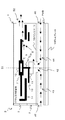
次に、第6の実施形態に係るディスク装置について、図面を参照しながら説明する。図9は、第6の実施の形態に係るディスク装置を説明するための図であり、(a)は平面図、(b)は(a)のD−D断面図、(c)は正面図、(d)は側面図である。図9において、61はディスク装置、2は筐体、3は筐体2の前面を構成する筐体前面部、4は筐体2の筐体前面部3を除いた側面部と上面部を形成するトップケース、68は第1の開口部、69及び70は第2の開口部、71及び72は案内路、73Aは塵埃堆積面、73B、73Cは塵埃堆積面をそれぞれ示している。なお、第2の開口部70は、第2の開口部69と対象のものである。また、図9において、矢印は空気の流れる方向を示している。
【0055】
第1の開口部68は、トップケース4の上面に形成され、ディスク収納室17内に外気を吸気するためのものである。また、塵埃堆積面73Aは、塵埃を堆積させるためのものであり、第1の開口部68とディスク収容室17との間に形成されている。この塵埃堆積面により、第1の開口部68から入った塵埃を堆積させることができるため、ディスク収容室17内に塵埃が侵入する量を少なくすることができる。なお、この塵埃堆積面73Aは、筐体2の外観面より1段低く絞った外形面に形成されている。
【0056】
また、トップケース4の上面には、第1の開口部68に外気を案内するための案内路71が形成されている。このため、第1の開口部68からディスク収納室17内に外気を効果的に案内することができる。例えば、後面からの外気を第1の開口部68に案内することができる。これにより、ディスク収容室17内の温度上昇を抑制することができる。
【0057】
また、図9(a)に示すように、第1の開口部68の上部を覆う部材73を設けるようにしてもよい。これにより、塵埃がディスク収容室内17に直接侵入することを防止できる。この部材73は、シリアルラベルのようなラベル状のものでもよいがこれには限定されない。
【0058】
また、第2の開口部69、70は、トップケース4の側面に形成され、ディスク収納室17内に外気を吸気するためのものである。この第2の開口部69、70とディスク収容室17との間に、塵埃を堆積させるための塵埃堆積面73B、73Cが形成されているため、第2の開口部69、70から入った塵埃を塵埃堆積面73B、73Cに堆積させることができる。これにより、ディスク収容室17内に入る塵埃の量を少なくすることができる。
【0059】
また、トップケース4の側面には、第2の開口部69、70に外気を案内するための案内路72が形成されている。このため、第2の開口部69、70に外気を案内することができる。また、左右側面に取り付けフレームと空間を確保できるため、第2の開口部69、70を塞がらないようにすることができる。また、上面又は下面からの外気を第2の開口部69、70に案内することもできる。
【0060】
また、図示は省略するが、第2の開口部69、70の上部を覆う部材を設けるようにしてもよい。これにより、塵埃が直接侵入して堆積するのを防止することができる。なお、本実施の形態では、第1の開口部68及び第2の開口部69、70は、円形に形成されているがこれには限定されない。また、部材73は、第1の開口部73の上部だけを覆うようにしているが、案内路71の上部を覆うようにしてもよい。
【0061】
図9では詳細な説明を省略するが、第1から第5の実施の形態と同様に、ディスク装置61の内部には、ディスクを駆動するディスク駆動機構を備えている。また、ディスク駆動機構は、ディスクを着脱可能に装着するターンテーブルと、ターンテーブルが取り付けられた回転軸を有するスピンドルモータと、ディスク圧着面によってディスクをターンテーブルのディスク基準面上に圧着して固定するチャッキングプリーとを有する。
【0062】
従来、例えばビルドインタイプのCDドライブ装置は、PC(パーソナルコンピュータ)ケースに配置されると、前後、背面以外の面からの空気の取り入れが困難である。特に、左右側面は穴を設けても取り付けによってふさがれてしまう場合が多い。この点、本実施の形態によれば、案内路71、72を設けることによりこの問題点を解決することができる。また、従来、天面に熱気を逃がす為の穴を設けた場合、上部に開口したその穴から塵埃が侵入しやすくなるが、本実施の形態によれば、第1の開口部68、第2の開口部69、70を覆う部材71を設けるようにしたので、上記問題点を解決できる。
【0063】
以上、本発明の一実施の形態を説明した。本発明は上記実施の形態に限定されるものではなく、本発明の要旨の範囲内において種々の変形実施が可能である。
【0064】
【発明の効果】
以上説明した本発明によれば、筐体上面に、ディスク収納室内に外気を吸気するための開口部を設けたので、この開口部を介して、ディスク収納室内に外気を吸気することにより、ディスク装置内部の温度上昇を抑制することができる。
【図面の簡単な説明】
【図1】第1の実施の形態に係るディスク装置の外観斜視図を示している。
【図2】第1の実施の形態に係るディスク装置を説明するための図であって、図1のA―A断面図を示している。
【図3】第2の実施の形態に係るディスク装置を説明するための図である。
【図4】第3の実施の形態に係るディスク装置の外観斜視図である。
【図5】第3の実施の形態に係るディスク装置を説明するための図であって、図4のB−B断面図である。
【図6】第4の実施の形態に係るディスク装置の外観斜視図である。
【図7】第4の実施の形態に係るディスク装置を説明するための図である。
【図8】第5の実施の形態に係るディスク装置を説明するための図である。
【図9】第6の実施の形態に係るディスク装置を説明するための図である。
【図10】従来のディスク装置を説明するための図である。
【符号の説明】
1、21、31、41、51 ディスク装置
18 第1の開口部
22 第2の開口部
32 第3の開口部
33、34 案内路
35、36 外気導入口
42 第1の開口部
43、44 案内路
45、46 外気導入口
52 第1の開口部
68 第1の開口部
69、70 第2の開口部
71、72 案内路
73A、73B、73C 塵埃堆積面
74 部材[0001]
TECHNICAL FIELD OF THE INVENTION
The present invention relates to a disk drive in which a disk drive mechanism and the like are arranged in a housing.
[0002]
[Prior art]
2. Description of the Related Art Conventionally, a disk device in which a disk drive mechanism and the like are arranged in a housing is known. In such a disk device, a signal processing board or the like is arranged in the housing with an internal partition wall therebetween, and each circuit is mounted on the signal processing board. Therefore, heat corresponding to power consumption is generated from the signal processing board. In addition, as the size of the disk device is reduced, a technique for mounting a forced cooling device such as a fan for preventing the above-described heat generation is also used in terms of space and power consumption.
[0003]
As a technique for solving such a conventional problem, a technique described in
[0004]
[Patent Document 1]
JP 2001-155479 A
[Problems to be solved by the invention]
However, in the conventional disk device, an exhaust opening 104, an
[0005]
SUMMARY OF THE INVENTION It is an object of the present invention to solve the above-mentioned problems of the prior art and to provide a disk device capable of suppressing a rise in temperature inside the disk device.
[0006]
[Means for Solving the Problems]
In order to solve the above-mentioned problems, a disk drive according to
[0007]
According to the first aspect of the present invention, since the first opening for sucking outside air into the disk storage chamber is provided on the upper surface of the housing, the disk rotates in the disk storage chamber by rotating the disk. Since the air pressure near the center decreases, outside air is sucked into the disk storage chamber through the first opening. As a result, an increase in the temperature inside the disk device can be suppressed.
[0008]
The disk device according to a second aspect of the present invention is the disk device according to the first aspect, further comprising: sucking outside air into the disk storage room or discharging air from the disk storage room to the side of the housing. And a second opening for providing the same.
[0009]
According to the second aspect of the invention, since the second opening for discharging the air in the disk storage chamber to the outside is provided on the side surface of the housing, the air is sucked into the disk storage chamber from the first opening. The generated air is efficiently exhausted to the outside of the disk storage chamber through the second opening. As a result, a rectifying effect can be expected as compared with the case where only the first opening is provided. Further, it is possible to suppress a rise in the temperature inside the disk device and to prevent dust contained in the outside air from accumulating in the disk device. Can also be prevented. Further, since the second opening is provided on the side surface of the housing, outside air can be sucked into the disk storage chamber.
[0010]
The disk device according to a third aspect of the present invention is the disk device according to the first or second aspect, further comprising a third opening in the partition wall for sucking outside air. According to the third aspect of the present invention, since the third opening is provided in the partition wall for taking in outside air, the rotation of the disk lowers the air pressure near the center of rotation of the disk in the disk storage chamber. The outside air is further sucked into the disk storage chamber through the third opening. As a result, an increase in the temperature inside the disk device can be suppressed.
[0011]
According to a fourth aspect of the present invention, in the disk device according to any one of the first to third aspects, the disk drive mechanism includes a turntable for detachably mounting the disk. A spindle motor having a rotating shaft to which the turntable is attached, wherein the first opening is formed on a rotating shaft of the spindle motor.
[0012]
According to the fourth aspect of the present invention, since the first opening is formed on the rotating shaft of the spindle motor, the first opening can be formed at the center of the upper surface of the housing where the disk rotates. it can. In other words, the first opening can be formed above the portion where the atmospheric pressure becomes lowest near the center of the disk as the disk rotates. Thereby, the outside air can be efficiently taken into the disk accommodating chamber.
[0013]
According to a fifth aspect of the present invention, in the disk device according to the third or fourth aspect, at least one of the first opening, the second opening, and the third opening is provided. A dust accumulation surface for accumulating dust is formed between one of the disc storage chambers.
[0014]
According to the invention described in
[0015]
The disk device according to a sixth aspect is the disk device according to any one of the third to fifth aspects, further comprising the first opening, the second opening, and the third opening. At least one of the openings has a guide path for guiding outside air or air in the storage room.
[0016]
According to the invention described in claim 6, since at least one of the first opening, the second opening, and the third opening has a guide path for guiding outside air or air in the storage chamber. The outside air can be effectively guided to each opening. As a result, it is possible to suppress an increase in the temperature in the disk storage chamber.
[0017]
The disk device according to a seventh aspect is the disk device according to any one of the third to sixth aspects, further comprising the first opening, the second opening, and the third opening. It has a member which covers at least one of the openings. According to the seventh aspect of the present invention, since there is a member that covers the first opening, the second opening, and the third opening, it is possible to prevent dust from directly entering from each opening.
[0018]
Further, in the disk device according to the present invention, a disk drive mechanism for driving a disk, a housing, and a disk housing chamber for housing the disk drive mechanism together with the housing are formed, and provided at a lower portion of the disk storage chamber. And a partition wall provided with a first opening for sucking outside air into the disk storage chamber.
[0019]
According to the eighth aspect of the present invention, since the first opening for sucking outside air into the disk storage chamber is provided on the lower surface of the housing, the rotation of the disk causes the rotation center of the disk in the disk storage chamber to rotate. Since the pressure in the vicinity decreases, outside air is sucked into the disk storage chamber through the first opening. As a result, an increase in the temperature inside the disk device can be suppressed.
[0020]
The disk device according to a ninth aspect of the present invention is the disk device according to the eighth aspect, further comprising: sucking outside air into the disk storage room or discharging air from the disk storage room to the side of the housing. And a second opening for providing the same.
[0021]
According to the ninth aspect of the present invention, since the second opening for sucking outside air into the disk storage chamber or discharging the air in the disk storage chamber to the outside is provided, the disk storage chamber can be opened from the first opening. The air taken into the disk compartment is efficiently exhausted to the outside of the disk storage chamber through the second opening. Accordingly, since the rectification effect is greater than when only the first opening is provided, it is possible to further suppress a rise in temperature inside the disk device and to prevent dust contained in the outside air from accumulating in the disk device. Can also be prevented. Further, the air in the storage chamber can be discharged to the outside from the second opening.
[0022]
According to a tenth aspect of the present invention, in the disk device according to the eighth or ninth aspect, further, the outside air or the air in the storage chamber is guided to the first opening or the second opening. Is provided. According to the tenth aspect of the present invention, since the guide path for guiding the outside air or the air in the storage chamber is provided in the first opening or the second opening, more outside air can be supplied through the guide path. It can be guided to the opening. As a result, a rise in the temperature inside the disk device can be further suppressed. Further, the air in the storage room can be guided through this guide path.
[0023]
BEST MODE FOR CARRYING OUT THE INVENTION
(First Embodiment)
Hereinafter, a disk drive according to an embodiment of the present invention will be described with reference to the drawings. FIG. 1 is an external perspective view of the disk device according to the first embodiment. 1 is a disk device, 2 is a housing, 3 is a housing front portion forming the front surface of the
[0024]
As shown in FIG. 2, the
[0025]
[0026]
On the upper surface of the
[0027]
Further, it is preferable that the
[0028]
(Second embodiment)
Next, a second embodiment will be described. In the present embodiment, in addition to the
[0029]
FIG. 3 is a diagram for explaining a disk device according to the second embodiment. As shown in FIG. 3, on the upper surface of the
[0030]
With the above configuration, the outside air sucked from the
[0031]
In the present embodiment, since the
[0032]
Further, since the
[0033]
Further, a
[0034]
(Third embodiment)
Next, a third embodiment will be described. FIG. 4 is an external perspective view of the disk device according to the third embodiment. 31 is a disk device, 2 is a housing, 3 is a housing front portion forming the front surface of the
[0035]
As shown in FIG. 5, on the upper surface of the
[0036]
A second opening for discharging air in the
[0037]
With the above configuration, the outside air that has been sucked into the
[0038]
According to the present embodiment, since the
[0039]
Further, since the
[0040]
Further, a
[0041]
Further, since the
[0042]
(Fourth embodiment)
Next, a fourth embodiment will be described. FIG. 6 is an external perspective view of the disk device according to the fourth embodiment. In the drawing,
[0043]
The disk drive mechanism 8 includes a turntable 9 on which the
[0044]
Further, the
[0045]
Further, the main chassis 16 is provided with a
[0046]
With the above configuration, the outside air introduced through the
[0047]
According to the present embodiment, since the
[0048]
Further, since the
[0049]
(Fifth embodiment)
Next, a fifth embodiment will be described. FIG. 8 is a diagram for explaining a disk device according to the fifth embodiment. In the present embodiment, in addition to the
[0050]
FIG. 8 is a diagram for explaining a disk device according to the fifth embodiment. As shown in FIG. 8, the main chassis 16 has a
[0051]
With the above configuration, the outside air introduced through the
[0052]
According to the present embodiment, since the
[0053]
In addition, since the
[0054]
(Sixth embodiment)
Next, a disk device according to a sixth embodiment will be described with reference to the drawings. 9A and 9B are views for explaining a disk drive according to a sixth embodiment, wherein FIG. 9A is a plan view, FIG. 9B is a cross-sectional view taken along line DD of FIG. 9A, and FIG. (D) is a side view. In FIG. 9,
[0055]
The
[0056]
In addition, a
[0057]
Further, as shown in FIG. 9A, a
[0058]
The
[0059]
A
[0060]
Although not shown, a member that covers the upper portions of the
[0061]
Although detailed description is omitted in FIG. 9, a disk drive mechanism for driving a disk is provided inside the
[0062]
2. Description of the Related Art Conventionally, for example, when a build-in type CD drive device is arranged in a PC (personal computer) case, it is difficult to take in air from surfaces other than front, rear, and back. In particular, the left and right side surfaces are often closed by mounting even if holes are provided. In this regard, according to the present embodiment, providing the
[0063]
The embodiment of the present invention has been described above. The present invention is not limited to the above embodiments, and various modifications can be made within the scope of the present invention.
[0064]
【The invention's effect】
According to the present invention described above, since the opening for sucking outside air into the disk storage chamber is provided on the upper surface of the housing, the outside air is sucked into the disk storage chamber through this opening, so that the disk is sucked. Temperature rise inside the device can be suppressed.
[Brief description of the drawings]
FIG. 1 is an external perspective view of a disk device according to a first embodiment.
FIG. 2 is a diagram for explaining the disk device according to the first embodiment, and is a cross-sectional view taken along line AA of FIG. 1;
FIG. 3 is a diagram for explaining a disk device according to a second embodiment.
FIG. 4 is an external perspective view of a disk device according to a third embodiment.
FIG. 5 is a diagram for explaining a disk device according to a third embodiment, and is a cross-sectional view taken along line BB of FIG. 4;
FIG. 6 is an external perspective view of a disk device according to a fourth embodiment.
FIG. 7 is a diagram for explaining a disk device according to a fourth embodiment.
FIG. 8 is a diagram for explaining a disk device according to a fifth embodiment.
FIG. 9 is a diagram for describing a disk device according to a sixth embodiment.
FIG. 10 is a diagram for explaining a conventional disk device.
[Explanation of symbols]
1, 21, 31, 41, 51 disk devices
18 First opening
22 Second opening
32 Third opening
33, 34 Guideway
35, 36 Outside air inlet
42 first opening
43, 44 Guideway
45, 46 Outside air inlet
52 first opening
68 first opening
69, 70 Second opening
71, 72 Guideway
73A, 73B, 73C Dust accumulation surface
74 members
Claims (10)
前記筐体の上面に、前記ディスク収納室内に外気を吸気するための第1の開口部を設けたことを特徴とするディスク装置。A disk drive comprising: a disk drive mechanism that drives a disk; a housing; a disk storage chamber that houses the disk drive mechanism together with the housing; and a partition provided below the disk storage chamber. ,
A disk device, wherein a first opening for sucking outside air into the disk storage chamber is provided on an upper surface of the housing.
前記第1の開口部は、前記スピンドルモータの回転軸上に形成されることを特徴とする請求項1から請求項3のいずれか一項に記載のディスク装置。The disk drive mechanism includes a turntable for detachably mounting the disk, and a spindle motor having a rotation shaft to which the turntable is mounted,
4. The disk device according to claim 1, wherein the first opening is formed on a rotation axis of the spindle motor. 5.
前記隔壁に、前記ディスク収納室内に外気を吸気するための第1の開口部を設けたことを特徴とするディスク装置。A disk drive comprising: a disk drive mechanism that drives a disk; a housing; a disk storage chamber that houses the disk drive mechanism together with the housing; and a partition provided below the disk storage chamber. ,
A disk device, wherein a first opening for sucking outside air into the disk storage chamber is provided in the partition.
Priority Applications (1)
| Application Number | Priority Date | Filing Date | Title |
|---|---|---|---|
| JP2003027291A JP2004241024A (en) | 2003-02-04 | 2003-02-04 | Disk drive |
Applications Claiming Priority (1)
| Application Number | Priority Date | Filing Date | Title |
|---|---|---|---|
| JP2003027291A JP2004241024A (en) | 2003-02-04 | 2003-02-04 | Disk drive |
Publications (1)
| Publication Number | Publication Date |
|---|---|
| JP2004241024A true JP2004241024A (en) | 2004-08-26 |
Family
ID=32955072
Family Applications (1)
| Application Number | Title | Priority Date | Filing Date |
|---|---|---|---|
| JP2003027291A Withdrawn JP2004241024A (en) | 2003-02-04 | 2003-02-04 | Disk drive |
Country Status (1)
| Country | Link |
|---|---|
| JP (1) | JP2004241024A (en) |
Cited By (4)
| Publication number | Priority date | Publication date | Assignee | Title |
|---|---|---|---|---|
| US7543310B2 (en) | 2005-02-15 | 2009-06-02 | Hitachi - Lg Data Storage, Inc. | Optical disk apparatus with openings for discharging air from therein |
| US7640558B2 (en) | 2006-05-29 | 2009-12-29 | Hitachi, Ltd. | Optical disc drive |
| US7690008B2 (en) | 2005-05-20 | 2010-03-30 | Hitachi-Lg Data Storage, Inc. | Optical disc drive having openings in the housing to allow air therein |
| US8584152B2 (en) | 2009-01-07 | 2013-11-12 | Panasonic Corporation | Disc drive with heat dissipating ventilation |
-
2003
- 2003-02-04 JP JP2003027291A patent/JP2004241024A/en not_active Withdrawn
Cited By (4)
| Publication number | Priority date | Publication date | Assignee | Title |
|---|---|---|---|---|
| US7543310B2 (en) | 2005-02-15 | 2009-06-02 | Hitachi - Lg Data Storage, Inc. | Optical disk apparatus with openings for discharging air from therein |
| US7690008B2 (en) | 2005-05-20 | 2010-03-30 | Hitachi-Lg Data Storage, Inc. | Optical disc drive having openings in the housing to allow air therein |
| US7640558B2 (en) | 2006-05-29 | 2009-12-29 | Hitachi, Ltd. | Optical disc drive |
| US8584152B2 (en) | 2009-01-07 | 2013-11-12 | Panasonic Corporation | Disc drive with heat dissipating ventilation |
Similar Documents
| Publication | Publication Date | Title |
|---|---|---|
| US11815965B2 (en) | Cooler with wireless charging function for mobile electronic device | |
| US8902581B2 (en) | Electronic device | |
| JP2002169626A (en) | Electronic equipment incorporating central processing unit | |
| JP2005149684A (en) | Disk array device | |
| TWI277068B (en) | Optical disk apparatus | |
| JP2010245200A (en) | Electronic apparatus | |
| US8587940B2 (en) | Server with fan module | |
| JP2004241024A (en) | Disk drive | |
| JPH10133782A (en) | Portable electronic equipment | |
| JP2011250983A (en) | Game machine | |
| JP2007188599A (en) | Electronic device | |
| JP2006286778A (en) | Cooling device of electronic equipment | |
| US20050018399A1 (en) | Electronic apparatus with cooling fan | |
| JP2000059061A (en) | Electronic equipment housing device and electric equipment housing case | |
| JP2009086704A (en) | Electronic device | |
| JP2012034733A (en) | Gaming machine | |
| JP2010232327A (en) | Device equipped with cooling mechanism, and cooling mechanism | |
| JP2006108324A (en) | Electronic device | |
| WO2007077709A1 (en) | Disk device | |
| JP2004127467A (en) | Storage device and electronic device equipped with storage device | |
| KR200472012Y1 (en) | A computer case had exhaust-fan used a hard-drive | |
| TWI796122B (en) | Electronic device | |
| CN220442120U (en) | Storage bag and palm electronic equipment assembly | |
| CN219961217U (en) | Electronic equipment | |
| JPH09274791A (en) | Magnetic disk device and electronic device |
Legal Events
| Date | Code | Title | Description |
|---|---|---|---|
| A621 | Written request for application examination |
Free format text: JAPANESE INTERMEDIATE CODE: A621 Effective date: 20060120 |
|
| A977 | Report on retrieval |
Effective date: 20080409 Free format text: JAPANESE INTERMEDIATE CODE: A971007 |
|
| A131 | Notification of reasons for refusal |
Effective date: 20080422 Free format text: JAPANESE INTERMEDIATE CODE: A131 |
|
| A761 | Written withdrawal of application |
Effective date: 20080516 Free format text: JAPANESE INTERMEDIATE CODE: A761 |