JP2004237766A - Gas fuel tank attaching structure for vehicle - Google Patents
Gas fuel tank attaching structure for vehicle Download PDFInfo
- Publication number
- JP2004237766A JP2004237766A JP2003026050A JP2003026050A JP2004237766A JP 2004237766 A JP2004237766 A JP 2004237766A JP 2003026050 A JP2003026050 A JP 2003026050A JP 2003026050 A JP2003026050 A JP 2003026050A JP 2004237766 A JP2004237766 A JP 2004237766A
- Authority
- JP
- Japan
- Prior art keywords
- gas fuel
- fuel tank
- floor panel
- bracket
- vehicle
- Prior art date
- Legal status (The legal status is an assumption and is not a legal conclusion. Google has not performed a legal analysis and makes no representation as to the accuracy of the status listed.)
- Pending
Links
Images


Landscapes
- Cooling, Air Intake And Gas Exhaust, And Fuel Tank Arrangements In Propulsion Units (AREA)
Abstract
Description
【0001】
【発明の属する技術分野】
本発明は、ガス燃料で走行する車両のガス燃料タンク取付構造に関するものである。
【0002】
【従来の技術】
天然ガスや水素ガス等のガス燃料を用いて走行する自動車が開発され、実用化されている。これらのガス燃料を充填するガス燃料タンクは、ガス燃料が圧縮した状態で充填されている。また、ガス燃料タンクは、加圧に耐えうるようにガソリンタンクに比べて強固に作られている。ガス燃料タンクを車体に取り付ける構造としては、リヤシート後方の荷室内に搭載するものがある(例えば、特許文献1参照。)。
【0003】
【特許文献1】
特開平7−186741号公報
【0004】
【発明が解決しようとする課題】
しかし、特許文献1のようにガス燃料タンクをリヤシート後方の荷室内に設けると、利用可能な荷室空間が減少するという問題がある。
また、車両の後突時に、ガス燃料タンクが荷室から前方に移動すると、ガス燃料タンクはリヤシートの乗員と接触する。ここで、ガス燃料タンクは強固に作られているため、ガス燃料タンクと乗員との接触は好ましくなく、ガス燃料タンクを強固に固定して一定の安全基準が確保されている。この固定構造を設けると、製造コストや車両重量が嵩むという問題があった。また、ガス燃料タンクがリヤシート後方に設けられていることから、レイアウト変更をしない限り、更なる安全性の向上を図るのは困難であった。
【0005】
本発明は、前記事情に鑑みてなされたものであり、その目的とするところは、荷室空間を効率よく利用することができ、車両後突時の乗員の安全性をより向上させるガス燃料タンク取付構造を提供することにある。
【0006】
【課題を解決するための手段】
前記目的を達成するため、請求項1に記載の発明は、ガス燃料が充填される筒状のガス燃料タンクを車体側に取り付ける車両のガス燃料タンク取付構造であって、ガス燃料タンクを幅方向に複数並べて設け、各ガス燃料タンクの長手方向に略直交する方向に延び各ガス燃料タンクを支持するブラケットを、車体のフロアパネルに固着したことを特徴とする。
【0007】
請求項1に記載の発明によれば、複数のガス燃料タンクは、車体のフロアパネルに固着されたブラケットによって支持される。即ち、ガス燃料タンクは、ブラケットを介してフロアパネルに直接的に取り付けられることとなる。また、ガス燃料タンクとブラケットは、互いの長手方向が略直交するように配置された状態でフロアパネルに固定される。
また、ガス燃料タンクとブラケットとがフロアパネルに固定された状態となるので、ブラケットがフロアパネルの変形を抑制する補強部材として機能することとなり、ガス燃料タンク及びブラケットにより、フロアパネルの直交する二方向の剛性が高められる。
【0008】
従って、荷室空間はガス燃料タンクによって占有されることがなくなり、従来のものに比べ、荷室空間の使用領域が広がるので、乗員は荷室空間を効率よく利用することができる。また、ガス燃料タンクをフロアパネルに直接的に取り付けることにより、車両の後突時にガス燃料タンクが前方に移動して乗員と接触することがなくなるので、乗員の安全性を向上させることができる。
また、フロアパネルの剛性が高められることにより、フロアパネルに取り付けられる従来公知のメンバを省くことができるので、車両の重量を低減できる。また、ガス燃料タンクはブラケットを介して直接的にフロアパネルに固定されているので、フロアパネル近傍の上下方向寸法を小さくすることもできる。
【0009】
請求項2に記載の発明は、ブラケットは、ガス燃料タンクのフロアパネル側を支持する第一支持部と、ガス燃料タンクのフロアパネルの反対側を支持し、第一支持部に着脱自在に固定される第二支持部と、を有することを特徴とする。
【0010】
請求項2に記載の発明によれば、請求項1の作用に加え、ブラケットを第一支持部と第二支持部とに自由に分割できる。即ち、ガス燃料タンクをブラケットから取り外す場合には、第二支持部を第一支持部から離脱させればよい。
従って、ガス燃料タンクやブラケットのメンテナンス作業を容易に行うことができる。
【0011】
請求項3に記載の発明は、第一支持部とフロアパネルとで、閉断面を形成したことを特徴とする。
【0012】
請求項4に記載の発明は、第一支持部と第二支持部とで、閉断面を形成したことを特徴とする。
【0013】
請求項3及び請求項4に記載の発明によれば、請求項1又は2の作用に加え、第一支持部とフロアパネル、第一支持部と第二支持部の少なくとも一方で閉断面を形成することによりブラケットの断面係数が増し、車両のフロアパネル廻りの剛性が更に高まる。
従って、車両の重量を増加させることなく効率的に剛性を向上させることができ、更なる車両重量の低減を図ることができる。
【0014】
請求項5に記載の発明は、ブラケットは、フロアパネルの左右方向に延びるように設けられ、第一支持部は、フロアパネルの下面に固着され、ブラケットに、フロアパネルの前後方向に延びるプロペラシャフトを挿通する挿通孔を形成したことを特徴とする。
【0015】
請求項5に記載の発明によれば、請求項2〜4のいずれか一項の作用に加え、ブラケットをフロアパネルの左右方向に延びるように設けたので、フロアパネルの左右方向に延び、フロアパネルを補強するクロスメンバとして機能する。
また、プロペラシャフトはブラケットの挿通孔に挿通されるので、フロアパネルにプロペラシャフトを挿通させるフロアトンネルを形成する必要がなくなる。
【0016】
従って、従来のようにフロアパネルを加工してフロアトンネルを形成する手間を省くことができ、車両の製造コストを低減できる。また、フロアトンネルを省くことにより、フロアパネルを略平坦に形成することができるので、荷重が集中的にかかる部分がなくなり、この結果、フロアパネル廻りの強度及び剛性を高めることができる。
【0017】
【発明の実施の形態】
以下、本発明に係る実施の形態の車両のガス燃料タンク取付構造について詳細に説明する。
本発明における車両のガス燃料タンク取付構造は、フロント側にエンジンが搭載される四輪駆動の自動車に設けられる。
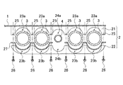
図1に示すように、ガス燃料タンク取付構造は、フロアパネル1と、フロアパネル1の下面側に固着されたブラケット2と、ブラケット2に支持されたガス燃料タンク3と、を備えている。
【0018】
フロアパネル1は略板状に形成されており、プロペラシャフト4を通すためのフロアトンネルは形成されていない。フロアパネル1の左右両側には、フロアパネル1と連続し、略前後に延びるサイドシル6が形成されている。
【0019】
ブラケット2は、ガス燃料タンク3を支持し、フロアパネル1の左右方向に延びるように配置され、その上面側が溶接等によって固着されている。本実施の形態においては、ブラケット2は、フロアパネル1のシートを取り付ける位置の下面側に配されている。ブラケット2は、図1及び図2に示すように、フロアパネル1の前後方向に三つ並んで設けられ、各ブラケット2間の間隔はほぼ等しくされている。また、フロアパネル1の最も前方側に固着されたブラケット2とダッシュパネル(図示しない)との間隔、フロアパネル1の最も後方側に固着されたブラケット2とリヤクロスメンバ(図示しない)との間隔は、それぞれブラケット2同士の間隔とほぼ等しく形成されている。
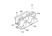
また、ブラケット2は、フロアパネル1に固着される第一支持部としての上部ブラケット21と、上部ブラケット21にボルト26を介して着脱自在に固定される第二支持部としての下部ブラケット22と、を備えている。
【0020】
上部ブラケット21は、略逆ハット状に形成されている。図2〜図4に示すように、この上部ブラケット21は、ガス燃料タンク3のフロアパネル1側を支持し、下面側が長手方向に所定の間隔をおいて複数箇所で、ガス燃料タンク3の半径とほぼ等しい略半円形状に湾曲形成され、この湾曲部分がガス燃料タンク3を取り付ける上取付部23aとして機能している。上取付部23aは、ガス燃料タンク3を取り付けた場合に、ガス燃料タンク3の最上部がフロアパネル1の高さ位置より若干低く位置するように形成されている。
また、上部ブラケット21の長手方向の中央の下面側は、略半円形状に湾曲形成され、この湾曲部分がプロペラシャフト4を挿通させる上挿通部24aとして機能している。また、上部ブラケット21の下面側には、湾曲部分を避けて、下部ブラケット22と接続するボルト孔が形成されている。また、ナット25が、その孔とボルト孔とを一致させるようにして、溶接等により固着されている。また、上部ブラケット21が略逆ハット状に形成され、上面側がフロアパネル1に固着されているため、フロアパネル1と上部ブラケット21とでフロアパネル1の左右方向断面にて閉断面が形成されている。また、上部ブラケット21の長手方向の両端部がサイドシル6に溶接等によって固着されている。
【0021】
下部ブラケット22は、ガス燃料タンク3のフロアパネル1の反対側を支持し、上面側が長手方向に所定の間隔をおいて複数箇所で、ガス燃料タンク3の半径とほぼ等しい略半円形状に湾曲形成され、この湾曲部分がガス燃料タンク3を取り付ける下取付部23bとして機能している。
また、下部ブラケット22の長手方向の中央部の下面側は、略半円形状に湾曲形成され、この湾曲部分がプロペラシャフト4を挿通させる下挿通部24bとして機能している。また、下部ブラケット22の上面側には、湾曲部分を避けて、上部ブラケット21に着脱自在に接続するときにボルト26を挿通するボルト孔が形成されている。また、下部ブラケット22とガス燃料タンク3との間には、ガス燃料タンク3のガタつきを防ぐバンド27が介在している。また、上部ブラケット21と下部ブラケット22とを接続することにより、上取付部23aと下取付部23bとによって円形状の取付部23が形成されている。また、上挿通部24aと下挿通部24bとによって円形状の挿通孔24が形成されている。
【0022】
ガス燃料タンク3は、円筒状に形成され、その内部には天然ガスや水素ガス等のガス燃料が加圧された状態で充填されている。ガス燃料タンク3は、ガソリン車の燃料タンクに比べて肉厚が厚く形成されている。また、ガス燃料タンク3は、通常走行時では破損しないような耐久性を有している。また、ガス燃料タンク3は、フロアパネル1の前後方向に延び、ガス燃料タンク3の幅方向に複数並んで設けられ、それぞれのガス燃料タンク3が上部ブラケット21の上取付部23aと下部ブラケット22の下取付部23bとに挟まれて支持されている。
【0023】
以上のように構成された車両のガス燃料タンク取付構造の作用について説明する。
複数のガス燃料タンク3は、フロアパネル1に固着されたブラケット2によって支持される。即ち、ガス燃料タンク3は、ブラケット2を介してフロアパネル1に直接的に取り付けられることとなる。また、ガス燃料タンク3とブラケット2は、互いの長手方向が略直交するように配置された状態でフロアパネル1に固定される。
また、ガス燃料タンク3とブラケット2とがフロアパネル1に固定された状態となるので、フロアパネル1が乗員の重量等によって負荷が変わると、変形を抑制する補強部材として機能することとなり、フロアパネル1の前後方向の剛性と左右方向の剛性を高めることができる。
【0024】
また、ブラケット2を上部ブラケット21と下部ブラケット22とに自由に分割できる。即ち、ガス燃料タンク3をブラケット2から取り外す場合には、ボルト26を外して、下部ブラケット22をフロアパネル1に固着された上部ブラケット21から離脱させればよい。よって、ガス燃料タンク3やブラケット2のメンテナンス作業を容易に行うことができる。また、ブラケット2全体をフロアパネル1から取り外す場合に比べて、離脱に関わる下部ブラケット22の重量の方が軽いので、作業者への負担を低減することができる。
【0025】
また、フロアパネル1と上部ブラケット21とで、閉断面を形成することによりブラケット2の断面係数が増し、これによって、車両のフロアパネル1廻りの剛性が高まる。よって、車両の重量を増加させることなく効率的に剛性を向上させることができ、更なる車両重量の低減を図ることができる。
【0026】
また、ブラケット2をフロアパネル1の左右方向に延びるように設けたので、フロアパネル1の左右方向に延び、フロアパネル1を補強するクロスメンバとして機能する。
また、プロペラシャフト4はブラケット2の挿通孔24に挿通されるので、フロアパネル1にプロペラシャフト4を挿通させるフロアトンネルを形成する必要がなくなる。
【0027】
従って、本実施の形態における車両のガス燃料タンク取付構造によれば、荷室空間はガス燃料タンク3によって占有されることがなくなり、従来のものに比べ、荷室空間の使用領域が広がるので、乗員は荷室空間を効率よく利用することができる。また、ガス燃料タンク3をフロアパネル1に直接的に取り付けることで、車両の後突時にガス燃料タンク3が前方に移動して乗員と接触することがなくなるので、乗員の安全性を向上させることができる。
【0028】
また、ガス燃料タンク3をフロアパネル1の前後方向に沿って設けた場合には、従来公知のサイドメンバの機能を果たし、サイドメンバを省くことができるので、車両の重量を低減できる。
これにより、フロアパネル1の下面側のサイドメンバによって占有される領域をなくし、フロアパネル1の地上からの高さを低くすることができる。即ち、フロアパネル1を比較的低い位置に設けることにより、フロアパネル1からルーフパネルまでの高さを高くすることができるので、室内空間の拡大化を図ることができる。また、フロアパネル1を低い位置に設けることで、シート等の設置位置も低くなり、車両の重心を低くすることができるので、車両の走行安定性を高めることができる。
【0029】
また、ガス燃料タンク3は、ブラケット2を介して直接的にフロアパネル1に固定されているので、フロアパネル1近傍の上下方向寸法を小さくすることができる。
また、ガス燃料タンク3をフロアパネル1に直接的に取り付けることで、フロアパネル1の振動抑制部材として機能するので、フロアパネル1の耐久性を向上させるとともに、フロアパネル1を介して車両の室内に侵入する騒音を低減することができる。
【0030】
また、ブラケット2にプロペラシャフト4を挿通させる挿通孔24を設けたので、フロアパネル1にプロペラシャフト4を挿通させるフロアトンネルを形成する必要がなく、従来のようにフロアパネル1を加工してフロアトンネルを形成する手間を省くことができ、車両の製造コストを低減できる。また、フロアトンネルを省くことにより、フロアパネル1を略平坦に形成することができるので、荷重が集中的にかかる部分がなくなり、この結果、フロアパネル1廻りの強度及び剛性を高めることができる。
【0031】
(変形例)
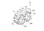
図5に示すように、本実施の形態の変形例におけるガス燃料タンク取付構造は、ブラケット5が前記のブラケット2と異なるものである。フロアパネル1、ガス燃料タンク3については、同様の構成を有するため、ここでは、ブラケット5について説明し、その他の構成要素については同一符号を付して説明を省略する。
ブラケット5は、フロアパネル1に固着される上部ブラケット51と、上部ブラケット51にボルト26を介して着脱自在に接続される下部ブラケット52と、を備えている。
【0032】
上部ブラケット51は、略ハット状に形成されている。この上部ブラケット51は、ガス燃料タンク3のフロアパネル1側を支持し、下面側が長手方向に所定の間隔をおいて複数箇所で、ガス燃料タンク3の半径とほぼ等しい略半円形状に湾曲形成され、この湾曲部分がガス燃料タンク3を取り付ける上取付部53aとして機能している。上取付部53aは、ガス燃料タンク3を取り付けた場合に、ガス燃料タンク3の最上部がフロアパネル1の高さ位置より若干低く位置するように形成されている。
また、上部ブラケット51の長手方向の中央の下面側は、プロペラシャフト4を挿通させることができるよう、略半円形状に湾曲され、この湾曲された部分が上挿通部54aとして機能している。また、上取付部53aの下面形状に沿って外側に向けて屈曲されたフランジ部51aが形成されている。また、フランジ部51aには、上取付部53aを避けて、下部ブラケット52と接続するボルト孔が形成されている。また、ナット25が、その孔とボルト孔とを一致させるようにして、溶接等により固着されている。また、上部ブラケット51は、長手方向の両端部がサイドシル6に溶接等によって固着されている。
【0033】
下部ブラケット52は、略逆ハット状に形成され、ガス燃料タンク3のフロアパネル1の反対側を支持し、上面側が長手方向に所定の間隔をおいて複数箇所で、ガス燃料タンク3の半径とほぼ等しい略半円形状に湾曲形成され、この湾曲部分がガス燃料タンク3を取り付ける下取付部53bとして機能している。また、下部ブラケット52の長手方向の中央部の下面側は、略半円形状に湾曲形成され、この湾曲部分がプロペラシャフト4を挿通させる下挿通部54bとして機能している。また、下取付部53bの上面形状に沿って外側に向けて屈曲されたフランジ部52aが形成されている。また、フランジ部52aには、下取付部53bを避けて、上部ブラケット51に着脱自在に接続するときにボルト26を挿通するボルト孔が形成されている。また、上部ブラケット51と下部ブラケット52とを接続することにより、フロアパネル1の左右方向断面にて閉断面が形成される。
【0034】
このように、本実施の形態の変形例におけるガス燃料タンク取付構造においては、ブラケット2と同様の作用効果を奏するのは勿論のこと、取付部53にフランジ部51a,52aを形成したので、ブラケット5自体の剛性を高め、ブラケット5の変形を抑制することができる。また、ボルト孔を形成したフランジ部51a,52aを設けたことにより、上下のブラケット5の位置合わせが容易となって、ブラケット5の外側から容易に着脱作業を行うことができる。
【0035】
なお、本発明は前記実施の形態に限定されるものではない。例えば、ブラケット2が取り付けられている位置のフロアパネル1の上面側にシート(図示しない)を取り付けるシート取付ブラケット(図示しない)を取り付けることにより、シートからの負荷をブラケット2により受けることができる。よって、シートクロスメンバを省いて車体の軽量化、製造コストの低減、ラインの簡易化を図ることができる。
また、ガス燃料タンク3の長手方向をフロアパネル1の左右方向に沿って配置し、ブラケット2の長手方向をフロアパネル1の前後方向に沿って配置してもよい。
また、フロアパネル1と上部ブラケット21、上部ブラケット21と下部ブラケット22がともに閉断面を形成するように構成してもよい。
【0036】
また、ガス燃料タンク3の積載数量は任意であって、車種によって積載数量を変更できる。例えば、ガス燃料タンク3の数量を増加することにより、フロアパネル1の剛性、強度、耐久性を向上させるとともに、燃料補給の機会の少ない場所でのガス燃料の補給回数を減らすことができる。また、例えば、ガス燃料タンク3の数量を必要最小限にとどめることにより、車重を軽くして燃費の向上を図り、経済的な走行を実現することができる。
【0037】
また、車両のフロント側にエンジンが搭載された四輪駆動式の自動車を例に挙げて説明したが、FF(フロントエンジンフロントドライブ)の自動車であってもよいし、FR(フロントエンジンリヤドライブ)の自動車であってもよい。なお、FFの自動車の場合には、プロペラシャフト4を挿通する挿通孔24は不要である。
【0038】
また、ブラケット2及びガス燃料タンク3は、フロアパネル1のリヤ側に設けてもよい。特に、FFの自動車においては、フロント側に重量が偏るため、リヤ側にガス燃料タンク3を設けることで、フロント側とリヤ側の重量差を減らし、車両の前後のバランスを良好にすることで、車両の走行安定性及び運動性能を向上させることができる。
【0039】
【発明の効果】
本発明によれば、荷室空間はガス燃料タンクによって占有されることがなくなり、従来のものに比べ、荷室空間の使用領域が広がるので、乗員は荷室空間を効率よく利用することができる。また、ガス燃料タンクをフロアパネルに直接的に取り付けることにより、車両の後突時にガス燃料タンクが前方に移動して乗員と接触することがなくなるので、乗員の安全性を向上させることができる。
また、フロアパネルの剛性が高められることにより、フロアパネルに取り付けられる従来公知のメンバを省くことができるので、車両の重量を低減できる。また、ガス燃料タンクはブラケットを介して直接的にフロアパネルに固定されているので、フロアパネル近傍の上下方向寸法を小さくすることもできる。
【図面の簡単な説明】
【図1】本発明の一実施形態におけるガス燃料タンク取付構造の概要図である。
【図2】ガス燃料タンク取付構造を説明する側面図である。
【図3】ガス燃料タンク取付構造を説明する断面図である。
【図4】ブラケットの斜視図である。
【図5】変形例におけるブラケットの斜視図である。
【符号の説明】
1 フロアパネル
2 ブラケット
21 上部ブラケット(第一支持部)
22 下部ブラケット(第二支持部)
24 挿通孔
3 ガス燃料タンク
4 プロペラシャフト[0001]
TECHNICAL FIELD OF THE INVENTION
The present invention relates to a gas fuel tank mounting structure for a vehicle running on gas fuel.
[0002]
[Prior art]
Automobiles that run using gas fuels such as natural gas and hydrogen gas have been developed and put into practical use. The gas fuel tank that fills these gas fuels is filled with the gas fuel compressed. Further, the gas fuel tank is made stronger than the gasoline tank so as to withstand pressurization. As a structure for attaching a gas fuel tank to a vehicle body, there is a structure in which the gas fuel tank is mounted in a luggage compartment behind a rear seat (for example, see Patent Document 1).
[0003]
[Patent Document 1]
Japanese Patent Application Laid-Open No. 7-186741
[Problems to be solved by the invention]
However, when the gas fuel tank is provided in the luggage compartment behind the rear seat as in
Further, when the gas fuel tank moves forward from the luggage compartment during a rear collision of the vehicle, the gas fuel tank comes into contact with the occupant in the rear seat. Here, since the gas fuel tank is made firmly, contact between the gas fuel tank and an occupant is not preferable, and a certain safety standard is secured by firmly fixing the gas fuel tank. When this fixing structure is provided, there is a problem that manufacturing cost and vehicle weight increase. Further, since the gas fuel tank is provided behind the rear seat, it is difficult to further improve safety unless the layout is changed.
[0005]
The present invention has been made in view of the above circumstances, and an object of the present invention is to provide a gas fuel tank capable of efficiently using a luggage space and further improving the safety of an occupant in a vehicle rear collision. It is to provide a mounting structure.
[0006]
[Means for Solving the Problems]
In order to achieve the above object, an invention according to
[0007]
According to the first aspect, the plurality of gas fuel tanks are supported by the bracket fixed to the floor panel of the vehicle body. That is, the gas fuel tank is directly attached to the floor panel via the bracket. Further, the gas fuel tank and the bracket are fixed to the floor panel in a state where the longitudinal directions of the gas fuel tank and the bracket are substantially orthogonal to each other.
In addition, since the gas fuel tank and the bracket are fixed to the floor panel, the bracket functions as a reinforcing member for suppressing deformation of the floor panel. The rigidity in the direction is increased.
[0008]
Therefore, the luggage space is no longer occupied by the gas fuel tank, and the use area of the luggage space is expanded as compared with the conventional one, so that the occupant can use the luggage space efficiently. Further, by directly attaching the gas fuel tank to the floor panel, the gas fuel tank does not move forward and come into contact with the occupant at the time of a rear collision of the vehicle, so that occupant safety can be improved.
In addition, by increasing the rigidity of the floor panel, a conventionally known member attached to the floor panel can be omitted, so that the weight of the vehicle can be reduced. Further, since the gas fuel tank is directly fixed to the floor panel via the bracket, the vertical dimension near the floor panel can be reduced.
[0009]
According to the second aspect of the present invention, the bracket supports the first support portion supporting the floor panel side of the gas fuel tank, and supports the opposite side of the floor panel of the gas fuel tank, and is detachably fixed to the first support portion. And a second support portion to be formed.
[0010]
According to the second aspect of the present invention, in addition to the function of the first aspect, the bracket can be freely divided into the first support portion and the second support portion. That is, when removing the gas fuel tank from the bracket, the second support portion may be separated from the first support portion.
Therefore, maintenance work of the gas fuel tank and the bracket can be easily performed.
[0011]
The invention according to
[0012]
The invention described in
[0013]
According to the third and fourth aspects of the invention, in addition to the function of the first or second aspect, a closed cross section is formed in at least one of the first support portion and the floor panel, and the first support portion and the second support portion. By doing so, the section modulus of the bracket increases, and the rigidity around the floor panel of the vehicle further increases.
Therefore, the rigidity can be efficiently improved without increasing the weight of the vehicle, and the weight of the vehicle can be further reduced.
[0014]
According to a fifth aspect of the present invention, the bracket is provided so as to extend in the left-right direction of the floor panel, the first support portion is fixed to a lower surface of the floor panel, and the propeller shaft extends in the bracket in the front-rear direction of the floor panel. Characterized in that an insertion hole for inserting the through hole is formed.
[0015]
According to the fifth aspect of the invention, in addition to the function of any one of the second to fourth aspects, the bracket is provided so as to extend in the left-right direction of the floor panel. Functions as a cross member to reinforce the panel.
Further, since the propeller shaft is inserted through the insertion hole of the bracket, it is not necessary to form a floor tunnel for inserting the propeller shaft into the floor panel.
[0016]
Therefore, it is possible to save the labor of forming the floor tunnel by processing the floor panel as in the related art, and to reduce the manufacturing cost of the vehicle. In addition, since the floor panel can be formed substantially flat by omitting the floor tunnel, there is no portion where the load is concentrated, and as a result, the strength and rigidity around the floor panel can be increased.
[0017]
BEST MODE FOR CARRYING OUT THE INVENTION
Hereinafter, a gas fuel tank mounting structure for a vehicle according to an embodiment of the present invention will be described in detail.
The gas fuel tank mounting structure for a vehicle according to the present invention is provided in a four-wheel drive automobile having an engine mounted on the front side.
As shown in FIG. 1, the gas fuel tank mounting structure includes a
[0018]
The
[0019]
The
The
[0020]
The
The lower surface of the
[0021]
The
The lower surface side of the central portion in the longitudinal direction of the
[0022]
The
[0023]
The operation of the gas fuel tank mounting structure for a vehicle configured as described above will be described.
The plurality of
In addition, since the
[0024]
Further, the
[0025]
In addition, by forming a closed cross section between the
[0026]
Further, since the
Further, since the
[0027]
Therefore, according to the gas fuel tank mounting structure of the vehicle in the present embodiment, the luggage space is no longer occupied by the
[0028]
When the
Thereby, the area occupied by the side members on the lower surface side of the
[0029]
Further, since the
In addition, by directly attaching the
[0030]
Further, since the
[0031]
(Modification)
As shown in FIG. 5, in a gas fuel tank mounting structure according to a modification of the present embodiment, a bracket 5 is different from the
The bracket 5 includes an
[0032]
The
The lower surface side of the center of the
[0033]
The
[0034]
As described above, in the gas fuel tank mounting structure according to the modified example of the present embodiment, not only the same operation and effect as the
[0035]
The present invention is not limited to the above embodiment. For example, by mounting a seat mounting bracket (not shown) for mounting a seat (not shown) on the upper surface side of the
Further, the longitudinal direction of the
Further, the
[0036]
Further, the loading quantity of the
[0037]
Also, a four-wheel drive type vehicle in which an engine is mounted on the front side of the vehicle has been described as an example, but the vehicle may be a FF (front engine front drive) or FR (front engine rear drive). Car. In the case of an FF automobile, the insertion hole 24 for inserting the
[0038]
Further, the
[0039]
【The invention's effect】
According to the present invention, the luggage space is no longer occupied by the gas fuel tank, and the area of use of the luggage space is expanded as compared with the related art, so that the occupant can use the luggage space efficiently. . Further, by directly attaching the gas fuel tank to the floor panel, the gas fuel tank does not move forward and come into contact with the occupant at the time of a rear collision of the vehicle, so that occupant safety can be improved.
Further, since the rigidity of the floor panel is increased, a conventionally known member attached to the floor panel can be omitted, so that the weight of the vehicle can be reduced. In addition, since the gas fuel tank is directly fixed to the floor panel via the bracket, the vertical dimension near the floor panel can be reduced.
[Brief description of the drawings]
FIG. 1 is a schematic view of a gas fuel tank mounting structure according to an embodiment of the present invention.
FIG. 2 is a side view illustrating a gas fuel tank mounting structure.
FIG. 3 is a sectional view illustrating a gas fuel tank mounting structure.
FIG. 4 is a perspective view of a bracket.
FIG. 5 is a perspective view of a bracket in a modified example.
[Explanation of symbols]
1
22 Lower bracket (second support part)
24
Claims (5)
前記ガス燃料タンクを幅方向に複数並べて設け、
各ガス燃料タンクの長手方向に略直交する方向に延び各ガス燃料タンクを支持するブラケットを、車体のフロアパネルに固着したことを特徴とする車両のガス燃料タンク取付構造。A gas fuel tank mounting structure for a vehicle in which a cylindrical gas fuel tank filled with gas fuel is mounted on a vehicle body side,
A plurality of the gas fuel tanks are provided side by side in the width direction,
A gas fuel tank mounting structure for a vehicle, wherein a bracket extending in a direction substantially perpendicular to a longitudinal direction of each gas fuel tank and supporting each gas fuel tank is fixed to a floor panel of a vehicle body.
前記ガス燃料タンクの前記フロアパネル側を支持する第一支持部と、
前記ガス燃料タンクの前記フロアパネルの反対側を支持し、前記第一支持部に着脱自在に固定される第二支持部と、
を有することを特徴とする請求項1に記載の車両のガス燃料タンク取付構造。The bracket is
A first support portion that supports the floor panel side of the gas fuel tank,
A second support portion that supports the opposite side of the floor panel of the gas fuel tank and is detachably fixed to the first support portion,
The gas fuel tank mounting structure for a vehicle according to claim 1, further comprising:
前記第一支持部は、前記フロアパネルの下面に固着され、
前記ブラケットに、前記フロアパネルの前後方向に延びるプロペラシャフトを挿通する挿通孔を形成したことを特徴とする請求項2〜4のいずれか一項に記載の車両のガス燃料タンク取付構造。The bracket is provided so as to extend in the left-right direction of the floor panel,
The first support portion is fixed to a lower surface of the floor panel,
5. The gas fuel tank mounting structure for a vehicle according to claim 2, wherein an insertion hole through which a propeller shaft extending in a front-rear direction of the floor panel is inserted is formed in the bracket. 6.
Priority Applications (1)
| Application Number | Priority Date | Filing Date | Title |
|---|---|---|---|
| JP2003026050A JP2004237766A (en) | 2003-02-03 | 2003-02-03 | Gas fuel tank attaching structure for vehicle |
Applications Claiming Priority (1)
| Application Number | Priority Date | Filing Date | Title |
|---|---|---|---|
| JP2003026050A JP2004237766A (en) | 2003-02-03 | 2003-02-03 | Gas fuel tank attaching structure for vehicle |
Publications (1)
| Publication Number | Publication Date |
|---|---|
| JP2004237766A true JP2004237766A (en) | 2004-08-26 |
Family
ID=32954176
Family Applications (1)
| Application Number | Title | Priority Date | Filing Date |
|---|---|---|---|
| JP2003026050A Pending JP2004237766A (en) | 2003-02-03 | 2003-02-03 | Gas fuel tank attaching structure for vehicle |
Country Status (1)
| Country | Link |
|---|---|
| JP (1) | JP2004237766A (en) |
Cited By (4)
| Publication number | Priority date | Publication date | Assignee | Title |
|---|---|---|---|---|
| JP2019031238A (en) * | 2017-08-09 | 2019-02-28 | トヨタ自動車株式会社 | Vehicle lower part structure |
| CN109562689A (en) * | 2016-08-11 | 2019-04-02 | 斯堪尼亚商用车有限公司 | Fuel tank attachment structure for motor vehicles |
| JP2019142391A (en) * | 2018-02-22 | 2019-08-29 | いすゞ自動車株式会社 | Fuel tank support structure |
| JP2021179230A (en) * | 2020-05-13 | 2021-11-18 | 八千代工業株式会社 | High-pressure vessel |
-
2003
- 2003-02-03 JP JP2003026050A patent/JP2004237766A/en active Pending
Cited By (6)
| Publication number | Priority date | Publication date | Assignee | Title |
|---|---|---|---|---|
| CN109562689A (en) * | 2016-08-11 | 2019-04-02 | 斯堪尼亚商用车有限公司 | Fuel tank attachment structure for motor vehicles |
| CN109562689B (en) * | 2016-08-11 | 2022-01-25 | 斯堪尼亚商用车有限公司 | Fuel tank attachment structure for motor vehicle |
| JP2019031238A (en) * | 2017-08-09 | 2019-02-28 | トヨタ自動車株式会社 | Vehicle lower part structure |
| JP2019142391A (en) * | 2018-02-22 | 2019-08-29 | いすゞ自動車株式会社 | Fuel tank support structure |
| JP2021179230A (en) * | 2020-05-13 | 2021-11-18 | 八千代工業株式会社 | High-pressure vessel |
| JP7273762B2 (en) | 2020-05-13 | 2023-05-15 | 八千代工業株式会社 | pressure vessel |
Similar Documents
| Publication | Publication Date | Title |
|---|---|---|
| US11420686B2 (en) | Lower vehicle-body structure of electric vehicle | |
| US7658440B2 (en) | Arrangement structure for auxiliary component of vehicle | |
| US20110284299A1 (en) | Vehicle structure of a hybrid vehicle | |
| JP5532877B2 (en) | Vehicle battery arrangement structure | |
| JP2007015591A (en) | Fuel cell vehicle | |
| JP4700031B2 (en) | Mounting structure for vehicle canister | |
| JP4678473B2 (en) | Vehicle fuel tank arrangement structure | |
| JP4858048B2 (en) | Lower body structure of automobile | |
| JP4073932B2 (en) | Vehicle fuel tank arrangement structure | |
| JP4098324B2 (en) | Vehicle fuel tank arrangement structure | |
| JP2004237766A (en) | Gas fuel tank attaching structure for vehicle | |
| JP2008037198A (en) | Vehicle body structure | |
| JP2006290013A (en) | Seat arranging structure of vehicle | |
| JP4529469B2 (en) | Vehicle fuel tank mounting structure | |
| JP4635690B2 (en) | Auxiliary equipment arrangement structure of vehicle | |
| JP2018161934A (en) | Floor structure of vehicle body | |
| JP2005247177A (en) | Vehicular fuel tank supporting structure | |
| JP2011157013A (en) | Vehicle lower structure | |
| JP5082794B2 (en) | Vehicle tank arrangement structure | |
| JP4967327B2 (en) | Vehicle seat arrangement structure | |
| JP2008037305A (en) | Vehicle body structure | |
| JP2008110634A (en) | Lower body structure of vehicle | |
| JP2006290141A (en) | Lower bodywork of vehicle | |
| JP2006051943A (en) | Arrangement structure of fuel tank for vehicle | |
| JP7338231B2 (en) | Lower body structure of electric vehicle |