JP2004233030A - Cooling device - Google Patents
Cooling device Download PDFInfo
- Publication number
- JP2004233030A JP2004233030A JP2003108115A JP2003108115A JP2004233030A JP 2004233030 A JP2004233030 A JP 2004233030A JP 2003108115 A JP2003108115 A JP 2003108115A JP 2003108115 A JP2003108115 A JP 2003108115A JP 2004233030 A JP2004233030 A JP 2004233030A
- Authority
- JP
- Japan
- Prior art keywords
- cooling
- adsorber
- heat
- heating element
- heat medium
- Prior art date
- Legal status (The legal status is an assumption and is not a legal conclusion. Google has not performed a legal analysis and makes no representation as to the accuracy of the status listed.)
- Pending
Links
Images


Classifications
-
- Y—GENERAL TAGGING OF NEW TECHNOLOGICAL DEVELOPMENTS; GENERAL TAGGING OF CROSS-SECTIONAL TECHNOLOGIES SPANNING OVER SEVERAL SECTIONS OF THE IPC; TECHNICAL SUBJECTS COVERED BY FORMER USPC CROSS-REFERENCE ART COLLECTIONS [XRACs] AND DIGESTS
- Y02—TECHNOLOGIES OR APPLICATIONS FOR MITIGATION OR ADAPTATION AGAINST CLIMATE CHANGE
- Y02A—TECHNOLOGIES FOR ADAPTATION TO CLIMATE CHANGE
- Y02A30/00—Adapting or protecting infrastructure or their operation
- Y02A30/27—Relating to heating, ventilation or air conditioning [HVAC] technologies
- Y02A30/274—Relating to heating, ventilation or air conditioning [HVAC] technologies using waste energy, e.g. from internal combustion engine
-
- Y—GENERAL TAGGING OF NEW TECHNOLOGICAL DEVELOPMENTS; GENERAL TAGGING OF CROSS-SECTIONAL TECHNOLOGIES SPANNING OVER SEVERAL SECTIONS OF THE IPC; TECHNICAL SUBJECTS COVERED BY FORMER USPC CROSS-REFERENCE ART COLLECTIONS [XRACs] AND DIGESTS
- Y02—TECHNOLOGIES OR APPLICATIONS FOR MITIGATION OR ADAPTATION AGAINST CLIMATE CHANGE
- Y02B—CLIMATE CHANGE MITIGATION TECHNOLOGIES RELATED TO BUILDINGS, e.g. HOUSING, HOUSE APPLIANCES OR RELATED END-USER APPLICATIONS
- Y02B30/00—Energy efficient heating, ventilation or air conditioning [HVAC]
- Y02B30/62—Absorption based systems
- Y02B30/625—Absorption based systems combined with heat or power generation [CHP], e.g. trigeneration
Abstract
Description
【0001】
【発明の属する技術分野】
本発明は、複数の発熱体を収納する筐体内を冷却する冷却装置に関し、電話基地局内の電子機器の冷却に用いて好適である。
【0002】
【従来の技術】
従来から、例えば、携帯電話基地局等では、発熱する複数の電子機器等を収納する筐体からなる基地局の内部を冷却するために冷却装置が用いられている。このような冷却装置の一例が下記特許文献1に開示されている。
【0003】
この文献に開示されている冷却装置では、筐体内に比較的発熱量が多く高温となる第1発熱体と、第1発熱体より低温で冷却する必要がある第2発熱体とが収納されている。そして、第1発熱体から吸熱し、その吸熱した熱により吸着剤を加熱することにより稼働する冷却手段である吸着式冷凍機により、第2発熱体を冷却するようになっている。
【0004】
この冷却装置は、第1発熱体で発生する熱を集めてその集めた熱と熱媒体とを熱交換する第1集熱器と、第2発熱体で発生する熱を集めてその集めた熱と熱媒体とを熱交換する第2集熱器とを有し、この第1、第2集熱器を介して、第1発熱体からの吸熱、および第2発熱体の冷却を行なうようになっている。
【0005】
【特許文献1】
特開2002−100891号公報
【0006】
【発明が解決しようとする課題】
しかしながら、上記特許文献1では、第1、第2集熱器の構成に関して具体的に開示されていない。そこで、本発明者が、内部を熱媒体が流通するジャケット部材を第1、第2集熱器とし、これらを直接第1、第2発熱体に当接して、第1発熱体からの吸熱、および第2発熱体の冷却を行なう電話基地局用の冷却装置を試作評価したところ、以下の問題があることが明らかとなった。
【0007】
比較的発熱量が多く高温となる第1発熱体は、所謂パワー素子等であり、ジャケット部材を当接することにより、第1発熱体から良好に吸熱することが可能である。これに対し、第1発熱体より低温で冷却する必要がある第2発熱体は、各種素子を高密度に表面実装したプリント基板等であり、比較的複雑な形状をしているため、ジャケット部材を当接しても第2発熱体の冷却が良好に行なえないという不具合が発生することを見出した。
【0008】
本発明は、上記点を鑑みてなされたものであって、第1発熱体から吸熱した熱により稼働し、第2発熱体を良好に冷却することが可能な冷却装置を提供することを目的とする。
【0009】
【課題を解決するための手段】
上記目的を達成するため、請求項1に記載の発明では、筐体(1a)内に収納された第1発熱体(2)に熱媒体を循環して第1発熱体(2)から吸熱し、この吸熱した熱により稼働する冷却手段(4)が生成する冷却風によって、筐体(1a)内に収納された第2発熱体(3)を冷却することを特徴としている。
【0010】
これによると、冷却手段(4)は冷却風により第2発熱体(3)を冷却する。したがって、第2発熱体(3)が複雑な形状をしていたとしても、良好に冷却することが可能である。
【0011】
また、請求項2に記載の発明では、冷却手段(4)は、冷却風を発生する冷却風発生手段(3a、3b)を備え、冷風発生手段(3a、3b)は、第2発熱体(3)の冷却風上流側に隣接して配置されることを特徴としている。
【0012】
これによると、冷却風発生手段(3a、3b)が発生する冷却風により、第2発熱体(3)を効率良く冷却することが可能である。
【0013】
また、請求項3に記載の発明のように、冷却手段(4)は、蒸発した気相冷媒を吸着するとともに加熱されることによりその吸着していた冷媒を脱離する吸着剤が封入された吸着器(5)を備える吸着式冷凍機(4)とすることができる。
【0014】
また、請求項4に記載の発明では、吸着器(5)は、第1発熱体(2)および第2発熱体(3)とともに、筐体(1a)内の同一の架台(20)内に載置されることを特徴としている。
【0015】
これによると、吸着器(5)を第1発熱体(2)および第2発熱体(3)の近傍に配置し易い。したがって、吸着器(5)を備える冷却手段(4)をコンパクトにすることが可能である。
【0016】
また、請求項5に記載の発明では、冷却手段(4)は、吸着器(5)と第1発熱体(2)との間に熱媒体を循環する吸熱用配管(11)を備え、吸熱用配管(11)は、架台(20)の一部を構成することを特徴としている。
【0017】
これによると、吸熱用配管(11)を架台(20)の一部とし、架台(20)と冷却手段(4)とからなる構成を小型軽量化することが可能である。
【0018】
また、請求項6に記載の発明では、冷却手段(4)は、冷却風を発生する冷却風発生手段(3a、3b)を備え、冷却風発生手段(3a、3b)は、前記架台(20)内に載置されることを特徴としている。
【0019】
これによると、冷却風発生手段(3a、3b)を第1発熱体(2)および第2発熱体(3)の近傍に配置し易い。また、冷却風発生手段(3a、3b)を吸着器(5)の近傍に配置し易い。したがって、冷却風発生手段(3a、3b)を備える冷却手段(4)を一層コンパクトにすることが可能である。
【0020】
また、請求項7に記載の発明では、冷却手段(4)は、吸着器(5)と冷風発生手段(3a、3b)との間に冷却用の熱媒体を循環する冷却用配管(12)を備え、冷却用配管(12)は、前記架台(20)の一部を構成することを特徴としている。
【0021】
これによると、冷却用配管(12)を架台(20)の一部とし、架台(20)と冷却手段(4)とからなる構成を一層小型軽量化することが可能である。
【0022】
また、請求項8に記載の発明では、冷却手段(4)は、冷却風を発生する冷却風発生手段(3a、3b)を備え、吸着器(5)は、第1発熱体(2)とともに、筐体(1a)内の同一の第1架台(21)内に載置され、冷風発生手段(3a、3b)は、第2発熱体(3)とともに、筐体(1a)内の同一の第2架台(22)内に載置されることを特徴としている。
【0023】
これによると、第1発熱体(2)と第2発熱体(3)とが別々の架台(21、22)内に載置される場合であっても、吸着器(5)を第1発熱体(2)の近傍に配置し易く、冷却風発生手段(3a、3b)を第2発熱体(3)の近傍に配置し易い。したがって、吸着器(5)および冷却風発生手段(3a、3b)を備える冷却手段(4)をコンパクトにすることが可能である。
【0024】
また、請求項9に記載の発明では、冷却手段(4)は、吸着器(5)と第1発熱体(2)との間に熱媒体を循環する吸熱用配管(11)を備え、吸熱用配管(11)は、第1架台(21)の一部を構成することを特徴としている。
【0025】
これによると、吸熱用配管(11)を第1架台(21)の一部とし、第1架台(21)と冷却手段(4)とからなる構成を小型軽量化することが可能である。
【0026】
また、請求項10に記載の発明では、冷却手段(4)は、吸着器(5)と冷風発生手段(3a、3b)との間に冷却用の熱媒体を循環する冷却用配管(12)を備え、冷却用配管(12)は、第2架台(22)の一部を構成することを特徴としている。
【0027】
これによると、冷却用配管(12)を第2架台(22)の一部とし、第2架台(22)と冷却手段(4)とからなる構成を小型軽量化することが可能である。
【0028】
また、請求項11に記載の発明では、
冷却手段(4)は、
吸着器(5)を有する吸着器ユニット(51)と、
筐体(1a)内に設けられ、第1発熱体(2)に当接して第1発熱体(2)の熱を集める集熱器(2a)と、
吸着器ユニット(51)と集熱器(2a)とを連結するように設けられ、吸着器(5)と集熱器(2a)との間を循環する吸熱用の熱媒体を流通する第1配管部材(110)と、
筐体(1a)内に設けられ、冷却風を発生する冷却風発生手段(31)と、
吸着器ユニット(51)と冷却風発生手段(31)とを連結するように設けられ、吸着器(5)と冷却風発生手段(31)との間を循環する冷却用の熱媒体を流通する第2配管部材(120)と、
吸着器(5)の熱を筐体(1a)の外部へ放熱するための放熱器(8a、8b)を有する放熱器ユニット(81)と、
吸着器ユニット(51)と放熱器ユニット(81)とを連結するように設けられ、吸着器(5)と放熱器(8a、8b)との間を循環する放熱用の熱媒体を流通する第3配管部材(130)と、
第1配管部材(110)、第2配管部材(120)、および第3配管部材(130)の各熱媒体の流通経路にそれぞれ介設され、着接状態としたときに熱媒体の流通経路を連通し、離隔状態としたときに熱媒体の流通経路を遮断するように着脱が可能な流通経路接続手段(100)とを備えることを特徴としている。
【0029】
これによると、吸着器ユニット(51)、集熱器(2a)、冷却風発生手段(31)、放熱器ユニット(81)のいずれかに不具合等が発生した場合には、流通経路接続手段(100)を離隔状態として、当該ユニット等を容易に取り外すことができる。また、代替ユニット等を容易に取り付けることができる。このようにして、メンテナンス性を向上することができる。
【0030】
また、請求項12に記載の発明では、流通経路接続手段(100)は、第1配管部材(110)、第2配管部材(120)、および第3配管部材(130)のそれぞれ両端部に設けられていることを特徴としている。
【0031】
これによると、流通経路接続手段(100)を離隔して、吸着器ユニット(51)、集熱器(2a)、冷却風発生手段(31)、放熱器ユニット(81)のいずれかを取り外すときに、第1配管部材(110)、第2配管部材(120)、および第3配管部材(130)を残置することができる。したがって、一層メンテナンス性を向上することができる。
【0032】
また、請求項13に記載の発明では、流通経路接続手段(100)は、離隔したときには、熱媒体を流通経路内に封止することを特徴としている。
【0033】
これによると、吸着器ユニット(51)、集熱器(2a)、冷却風発生手段(31)、放熱器ユニット(81)の着脱時に熱媒体が流通経路から漏れることを防止できる。したがって、より一層メンテナンス性を向上することができる。
【0034】
また、請求項14に記載の発明では、筐体(1a)は、電話基地局(1)の外殻(1a)であり、第1発熱体(2)および第2発熱体(3)は、ともに前記外殻(1a)内に収納された電子機器(2、3)であることを特徴としている。
【0035】
これによると、電話基地局(1)の外殻(1a)内に収納された電子機器(2)の発熱を利用して冷却手段(4)を稼働し、冷却手段(4)が生成する冷却風によって、前記外殻(1a)内に収納された他の電子機器(3)を冷却することができる。
【0036】
なお、上記各手段に付した括弧内の符号は、後述する実施形態記載の具体的手段との対応関係を示す一例である。
【0037】
【発明の実施の形態】
以下、本発明の実施の形態を図に基づいて説明する。
【0038】
(第1の実施形態)
図1は、本発明の冷却装置が搭載される携帯電話の電話基地局1の概略模式構成図である。電話基地局1は、略密閉空間を形成する外殻をなす筐体1aの内部に通信用電子機器等を収納するものである。なお、本例では、筐体1aは、複数のアルミニウム板の間にウレタン発泡断熱材を挟装した部材により構成している。
【0039】
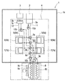
電話基地局1には、比較的発熱量が多く、かつ、高温となるパワーアンプ等からなる第1発熱体2と、第1発熱体2より低温で冷却する必要があり、各種素子を高密度に表面実装したプリント基板等に送受信回路等を形成してなる第2発熱体3と、両発熱体2、3を冷却する冷却手段(冷却装置)である冷凍機4(一点鎖線で囲まれた部分)とが設けられている。なお、両発熱体(電子機器)2、3は単独で(独立して)稼動するものではなく、両者2、3が連動して稼動するものである。
【0040】
ここで、冷凍機4は、第1発熱体2から吸熱し、その吸熱した熱により吸着剤を加熱することにより稼働する吸着式冷凍機であり、以下、吸着式冷凍機(冷凍機4)について述べる。
【0041】
なお、吸着剤は、冷媒(本実施形態では、水)を吸着するとともに、加熱されることにより吸着していた冷媒を脱離するもので、本実施形態では、シリカゲルを固体吸着剤として採用している。なお、固体吸着剤としてゼオライト等を採用することも可能である。
【0042】
5は内部が略真空に保たれた状態で冷媒が封入された吸着器であり、この吸着器5内には、吸着剤と熱媒体(本実施形態では、エチレングリコール系の不凍液が混入された水)とを熱交換する第1熱交換器(吸着コア)6と、熱媒体と吸着器5内に封入された冷媒とを熱交換する第2熱交換器(蒸発/凝縮コア)7とが収納されている。
【0043】
なお、本実施形態では、複数個(2個)の吸着器5a、5bから構成されており、紙面右側の吸着器5a(以下、第1吸着器5aと呼ぶ。)と紙面左側の吸着器5b(以下、第2吸着器5bと呼ぶ。)とは、同じ構成であるので、両者を総称して呼ぶときは、吸着器5と表記する。また、熱交換器6、7の添え字aは第1吸着器5a内の熱交換器であることを示し、bは第2吸着器5b内の熱交換器であることを示す。
【0044】
8は基地局1の建物(筐体1a)外に配設されて熱媒体と室外空気(放熱対象)とを熱交換する室外熱交換器(以下、室外器と略す。)であり、この室外器8は、第1、第2放熱器8a、8bおよび冷却風を送風するファン8cからなるもので、第1放熱器8aは第2放熱器8bより冷却風流れ上流側に設けられている。
【0045】
2aは第1発熱体2で発生する熱を集めてその集めた熱と熱媒体と熱交換させる集熱器であり、集熱器2aは、内部の熱媒体通路内にインナーフィンが形成されたアルミニウム製のジャケット部材からなり、第1発熱体2の表面に当接するように配置されている。集熱器2aと吸着器5とは吸熱用配管である温水用配管11により接続されており、温水用配管11に熱媒体を循環して、第1発熱体2から吸熱した熱媒体を吸着器5に戻すようになっている。
【0046】
3aは筐体1a内の空気と熱媒体とを熱交換する室内熱交換器であり、室内熱交換器3aと吸着器5とは冷却用配管である冷水用配管12により接続されている。そして、冷水用配管12に熱媒体を循環して、室内熱交換器3aを通過する空気を冷却するようになっている。なお、3bは室内熱交換器3aに並設された冷却風を送風するためのファンである。
【0047】
9a〜9eは冷凍機4内の熱媒体流れを切り替えるロータリ式バルブ(以下、バルブと呼ぶ。)である。10aは温水用配管11を介して集熱器2aに熱媒体を循環させるポンプであり、10bは冷水用配管12を介して室内熱交換器3aに熱媒体を循環させるポンプである。また、10cは室外器8に熱媒体を循環させるポンプである。
【0048】
ここで、冷凍機4の概略配置構成について説明する。
【0049】
図2は、冷凍機4の配置構成を示す概略構成図であり、図3は、後述する架台20に載置された冷凍機4の筐体1a内配置部分を示す概略構成図である。なお、図2および図3では、吸着器5の近傍に配設されたバルブ9a〜9eや、これらに連結した一部の配管等の図示を省略している。
【0050】
図2に示すように、冷凍機4のうち室外器8を除く部分は、筐体1a内の架台20に載置されている。なお、ポンプ10b、10cの配設位置が図1と図2とでは若干異なるが、本例の実際の配設位置は図2に示すものである。各ポンプ10a〜10cは、熱媒体の各循環経路内に配設されるものであれば、位置が限定されるものではない。
【0051】
図3に示すように、吸着器5は、架台20の最下部に載置され、吸着器5の両端部側から上方側に略L字形状の2本の温水用配管11が延設されている。温水用配管11の水平方向延設部には第1発熱体2が懸架され、第1発熱体2に当接配置された集熱器2aが両温水配管11と連通している。
【0052】
ここで図示は省略しているが、集熱器2aの温水用配管11との接続部には、着脱が容易で着脱時に熱媒体の漏れが発生し難い所謂ノンスピルジョイントが形成されている。したがって、故障時等には、集熱器2aを容易に取り外すことが可能となっている。
【0053】
温水用配管11として、本例では外径約26mmのステンレス製配管を採用している。20aは断面形状がL字状であるステンレス製のフレーム部材であり、フレーム部材20aと温水用配管11とは溶接もしくは螺子止め等により係止され、架台20を構成している。
【0054】
架台20の最上部には、図3中左方側の温水用配管11と連通するリザーブタンク13が配設されている。リザーブタンク13内に余剰の熱媒体を貯留することで、温度変化等に伴なう熱媒体の体積変化分を調整したり、万が一熱媒体漏れが発生した場合には、これを補うようになっている。
【0055】
吸着器5の両端部側から上方側には、2本の冷水用配管12が延設されている。なお、冷水用配管12も温水用配管11と同様に、架台20の一部を構成する構造部材として機能している。この2本の冷水用配管12の間には、ポンプ10bおよび室内熱交換器3aが配設されている。また、室内熱交換器3aの上方側にはファン3bが配設され、室内熱交換器3aに熱媒体を循環しつつファン3bを駆動することで、上方に向かって冷却風を送風するようになっている。室内熱交換器3aとファン3bとが本実施形態における冷却風発生手段である。
【0056】
ファン3bの直上には、水平方向に延設されたフレーム部材20aに第2発熱体3が懸架されている。すなわち、第2発熱体3はファン3bの冷却風下流側に隣接して配置されている。換言すれば、室内熱交換器3aとファン3bとからなる本実施形態の冷却風発生手段は、第2発熱体3の冷却風上流側に隣接して配置されている。
【0057】
次に、上記構成に基づき冷凍機(冷却装置)4の作動について説明する。
【0058】
冷凍機4(吸着式冷凍機)は、以下に述べる第1、第2作動モードを所定時間毎に切換運転するものである。ちなみに、所定時間は、吸着剤に吸着されていた冷媒を脱離させるに必要な時間に基づいて適宜選定されるものである。
【0059】
なお、本実施形態の第1発熱体2は表面が80℃以下(内部が120℃以下)となるように冷却(吸熱)されることが好ましく、第2発熱体3は60℃以下となるように冷却されることが好ましい。そのため、集熱器2aから流出する熱媒体の温度が75℃となり、第2発熱体3へ吹き込まれる冷却風の温度が35℃となるように冷凍機4の各種諸元が決定されている。
【0060】
図4に冷凍機4の第1作動モードを示す。このモードでは、室内熱交換器3aと第2吸着器5bの第2熱交換器7bとの間で熱媒体を循環させることにより、第2吸着器5b内の冷媒を蒸発させて室内熱交換器3aに冷却された熱媒体を供給することによって第2発熱体3に向けて冷却風を発生するとともに、第2吸着器5b内で蒸発した気相冷媒(水蒸気)を第2吸着器5b内の吸着剤にて吸着する。
【0061】
このとき、吸着剤は凝縮熱に相当する熱量を発熱し、かつ、吸着剤の温度が上昇すると吸着能力が低下するので、室外器8にて冷却された熱媒体を第2吸着器5bの第1熱交換器6bに供給することにより吸着剤を冷却する。
【0062】
一方、第1吸着器5aの第1熱交換器6aには、集熱器2aにて熱媒体に吸熱された熱を、熱媒体を介して第1吸着器5aの吸着剤に供給することより吸着剤を加熱し、吸着剤に吸着していた冷媒を脱離させるとともに、第1吸着器5aの第2熱交換器7aに室外器8にて冷却された熱媒体を供給し、その脱離した気相冷媒(水蒸気)を第2熱交換器7aにて冷却して凝縮させる。
【0063】
以下、冷媒を蒸発させて冷凍能力を発揮しつつ、その蒸発した気相冷媒を吸着剤にて吸着させている状態にある吸着器5のことを、「吸着工程にある吸着器5」と呼び、吸着剤を加熱して吸着していた冷媒を脱離させつつ、その脱離した冷媒を冷却凝縮させている状態にある吸着器5のことを、「脱離工程にある吸着器5」と呼ぶ。
【0064】
次に、図5に冷凍機4の第2作動モードを示す。このモードでは、第1作動モードとは逆に、第1吸着器5aを吸着工程とし、第2吸着器5bを脱離工程とするものである。
【0065】
具体的には、図5に示すように、室内熱交換器3aと第1吸着器5aの第2熱交換器7aとの間で熱媒体を循環させることにより、第1吸着器5a内の冷媒を蒸発させて室内熱交換器3aに冷却された熱媒体を供給することによって第2発熱体3に向けて冷却風を発生するとともに、第1吸着器5a内で蒸発した気相冷媒(水蒸気)を第1吸着器5a内の吸着剤にて吸着する。
【0066】
このとき、室外器8にて冷却された熱媒体を第1吸着器5aの第1熱交換器6aに供給することにより吸着剤を冷却する。
【0067】
一方、第2吸着器5bの第1熱交換器6bには、集熱器2aにて熱媒体に吸熱された熱を、熱媒体を介して第2吸着器5bの吸着剤に供給することより吸着剤を加熱し、吸着剤に吸着していた冷媒を脱離させるとともに、第2吸着器5bの第2熱交換器7bに室外器8にて冷却された熱媒体を供給し、その脱離した気相冷媒(水蒸気)を第2熱交換器7bにて冷却して凝縮させる。
【0068】
上述の構成および作動によれば、冷凍機4が第1、第2作動モードのいずれのモードであっても、室内熱交換器3aおよびファン3bにより発生する冷却風により第2発熱体3を冷却することができる。第2発熱体3は各種素子を高密度に表面実装したプリント基板等からなり、比較的複雑な形状をしているが、良好に冷却することができる。
【0069】
室内熱交換器3aおよびファン3bは、第2発熱体3の冷却風上流側に隣接配置されているので、第2発熱体3を効率良く冷却することができ、冷凍機4の作動モードの切換えを頻繁に行なうことを抑制できる。
【0070】
吸着式冷凍機4の冷却能力は、冷媒吸着量(水分吸着量)と吸着剤量によって決定される。したがって、同量の吸着剤を封入した吸着器を備える冷凍機であれば、冷媒吸着量が多いほど冷却能力が大きくなる。図6に本実施形態の吸着剤であるシリカゲルの水分吸着特性を示す。
【0071】
室外器8により冷却された熱媒体の温度を40℃、前述したように集熱器2aから流出し吸着器に戻る熱媒体の温度を75℃とし、35℃の冷却風を発生するために室内熱交換器3aに30℃の熱媒体を供給する場合には、吸着工程にある吸着器5内の相対湿度は0.58、脱離工程にある吸着器5内の相対湿度は0.19となる。したがって、図6に示す特性より、吸着工程において吸着剤が吸着できる水分量は約0.21g/gである。
【0072】
これに対し、室内熱交換器3aおよびファン3bが第2発熱体3の冷却風上流側に隣接配置されていない場合には、第2発熱体3の雰囲気を35℃以下とするためには、例えば室内熱交換器3aから30℃の冷却風を発生し、筐体1a内を全体的に冷却する必要がある。室外器8により冷却された熱媒体の温度を40℃、集熱器2aから流出し吸着器に戻る熱媒体の温度を75℃とし、30℃の冷却風を発生するために室内熱交換器3aに25℃の熱媒体を供給する場合には、吸着工程にある吸着器5内の相対湿度は0.43、脱離工程にある吸着器5内の相対湿度は0.19となる。したがって、図6に示す特性より、吸着工程において吸着剤が吸着できる水分量は約0.12g/gである。
【0073】
このように、室内熱交換器3aおよびファン3bを第2発熱体3の冷却風上流側に隣接配置して、第2発熱体3に直接冷却風を当てることで、上記例のように室内熱交換器3aへ供給する熱媒体の温度を5℃上昇することができれば、みかけ上冷却能力を約1.75倍とするが可能である。したがって、冷凍機4の作動モードの切換えを頻繁に行なうことを抑制できる。
【0074】
また、夏期等に外気温が上昇し室外器8により冷却された熱媒体の温度が上昇すると、吸着工程にある吸着器5内の相対湿度は低下し、脱離工程にある吸着器5内の相対湿度は上昇する。すなわち、外気温が上昇すると、吸着工程において吸着可能な水分量が減少し冷却能力が低下する。本実施形態では、第2発熱体3に直接冷却風を当てることで高い冷却能力を得易いので、外気温上昇時の冷却能力低下の影響を小さくすることができる。
【0075】
また、吸着器5、室内熱交換器3aおよびファン3b等の冷凍機4の室外器8を除く構成を、第1発熱体2および第2発熱体3とともに同一の架台20内に載置しており、冷凍機4をコンパクトにすることができる。吸着器5を第1発熱体2の近傍に配置して温水用配管11を短くすることができる。また、室内熱交換器3aを吸着器5の近傍に配置して冷水用配管12を短くすることができる。
【0076】
両配管11、12を短くすると、配管中を流通する熱冷媒からの吸放熱による熱損失を抑制するとともに、圧力損失を抑制することが可能である。圧力損失抑制によりポンプ10a、10bを低出力化することができ、省エネルギーおよびポンプ小型化が可能である。
【0077】
また、温水用配管11および冷水用配管12を、架台20の一部を構成する構造部材として兼用している。したがって、冷凍機4を搭載した架台20を小型軽量化することができる。
【0078】
(第2の実施形態)
次に、第2の実施形態について、図7に基づいて説明する。本第2の実施形態は、前述の第1の実施形態と比較して、吸着器と冷却風発生手段との配置関係が異なる。なお、第1の実施形態と同様の部分については、同一の符号をつけ、その説明を省略する。
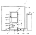
【0079】
図7に示すように、本実施形態の筐体1aは第1の実施形態の筐体より低背構造となっており、第1発熱体2は第1架台21に載置され、第2発熱体3は第2架台22に載置されている。そして、吸着器5は第1架台21の最下部に載置され、ポンプ10b、室内熱交換器3aおよびファン3bは第2架台22の第2発熱体3の直下に隣接配置され、冷却風を第2発熱体3に向けて送風するようになっている。
【0080】
本実施形態の温水用配管11は、フレーム部材21aと溶接もしくは螺子止め等により係止され、フレーム部材21aと温水用配管11とで第1架台21を構成している。また、本実施形態の冷水用配管12は、フレーム部材22aと溶接もしくは螺子止め等により係止され、フレーム部材22aと冷水用配管12とで第2架台22を構成している。
【0081】
上述の構成によれば、第1の実施形態と同様に、室内熱交換器3aおよびファン3bにより発生する冷却風により第2発熱体3を良好に冷却することができる。室内熱交換器3aおよびファン3bは、第2発熱体3の冷却風上流側に隣接配置されているので、第2発熱体3を効率良く冷却することができ、冷凍機4の作動モードの切換えを頻繁に行なうことを抑制できる。また、外気温上昇時の冷却能力低下の影響を小さくすることができる。
【0082】
また、吸着器5等を第1発熱体2とともに同一の第1架台21内に載置し、室内熱交換器3aおよびファン3b等を第2発熱体3とともに同一の第2架台22内に載置しており、冷凍機4をコンパクトにすることができる。吸着器5を第1発熱体2の近傍に配置して温水用配管11を短くすることができ、配管中を流通する熱冷媒からの放熱による熱損失を抑制するとともに、圧力損失を抑制することが可能である。
【0083】
また、温水用配管11を、第1架台21の一部を構成する構造部材として兼用し、冷水用配管12を、第2架台22の一部を構成する構造部材として兼用している。したがって、冷凍機4を搭載した第1、第2架台21、22を小型軽量化することができる。
【0084】
(第3の実施形態)
次に、第3の実施形態について、図8ないし図11に基づいて説明する。本第3の実施形態は、前述の第1の実施形態と比較して、熱媒体の各流通経路にジョイントを設けた点が異なる。なお、第1の実施形態と同様の部分については、同一の符号をつけ、その説明を省略する。
【0085】
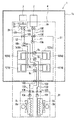
図8は、本実施形態の冷却装置が搭載される携帯電話の電話基地局1の概略模式構成図である。図8に示すように、本実施形態の冷却手段(冷却装置)である冷凍機4には、第1の実施形態において設けられていたバルブ9eを設けていない。また、第1、第2放熱器8a、8bは、分離して設けられた放熱用の熱媒体の循環経路に設けられている。
【0086】
さらに、第1、第2放熱器8a、8bに対応して、ポンプ10c、10d、およびファン8c、8dがそれぞれ設けられている。そして、第1放熱器8aを流れる熱媒体の循環経路はバルブ9c、9dに接続しており、第2放熱器8bを流れる熱媒体の循環経路はバルブ9a、9bに接続している。
【0087】
本実施形態の冷凍機4の主要部は、4つのユニットにより構成されている。4つのユニットとは、吸着器5、バルブ9a〜9d、ポンプ10a、10bを備える吸着器ユニット51、集熱器2aからなるユニット、室内熱交換器3a、ファン3bからなる冷却風発生ユニット(冷却風発生手段)31、および第1、第2放熱器8a、8b、ファン8c、8d、ポンプ10c、10dを備える放熱器ユニット81である。
【0088】
そして、温水用配管11のうち吸着器ユニット51と集熱器2aとを連結する部分の配管(本実施形態の第1配管部材)110の両端部、および冷水用配管12のうち吸着器ユニット51と冷却風発生ユニット31とを連結する部分の配管(本実施形態の第2配管部材)120の両端部には、ジョイント100が設けられている。
【0089】
また、第1、第2放熱器8a、8bに放熱用の熱媒体を循環する経路のうち、吸着器ユニット51と放熱器ユニット81とを連結する部分の配管(本実施形態の第3配管部材)130の両端部にもジョイント100が設けられている。
【0090】
換言すれば、吸着器ユニット51、集熱器2a、冷却風発生ユニット31、および放熱器ユニット81の各ユニットにおける熱媒体流通経路の出入口には、ジョイント100が設けられている。
【0091】
図9は、ジョイント100を含む本実施形態の冷凍機4の配置構成を示す概略構成図である。図9に示すように、本実施形態の吸着器ユニット51は、架台20内に載置されており、放熱器ユニット81は、筐体1aの外部に配設されている。なお、図9では、配管130のうち一部の図示を省略している。
【0092】
図10に示すように、ジョイント100は、雌側ハウジング101内に、雌側ハウジング101に対して固定されたバルブ本体部103と、バネ部材104により押圧されるとともに雌側ハウジング101に対してスライド可能なスライドバルブ102とを備えている。また、雄側ハウジング106内に、バネ部材108により押圧されるとともに雄側ハウジング106に対してスライド可能なバルブ本体部107を備えている。
【0093】
そして、図10(a)に示すように、雌側ハウジング101内に雄側ハウジング106を挿入着接し着接状態としたときには、雄側ハウジング106がスライドバルブ102を図中左方向にスライドさせるとともに、バルブ本体部103がバルブ本体部107を図中右方向にスライドさせ、破線で示したように熱媒体の流通経路が連通する。
【0094】
図10(b)に示すように、図10(a)に示す着接状態から、雌側ハウジング101内から雄側ハウジング106を脱離して離隔状態としたときには、雌側ハウジング101内では、バネ部材104がスライドバルブ102を図中右方向にスライドさせ、スライドバルブ102をバルブ本体部103に当接して、熱媒体の流通経路を遮断する。
【0095】
一方、雄側ハウジング106内では、バネ部材108がバルブ本体部107を図中左方向にスライドさせ、バルブ本体部107を雄側ハウジング106の内面に当接して、熱媒体の流通経路を遮断する。ジョイント100は、着脱可能な本実施形態における流通経路接続手段である。
【0096】
ジョイント100は、図10(b)に示す離隔状態となったときには、上記のように作動して熱媒体を流通経路内に封止し、熱媒体の漏れを防止する。ジョイント100は、所謂ノンスピルジョイントである。
【0097】
冷凍機4の作動は、放熱用熱媒体の流れが若干異なる点を除き第1の実施形態と同様であるので、詳細な説明は省略する。
【0098】
上述の構成によれば、第1の実施形態と同様に、冷却風発生ユニット31(室内熱交換器3aおよびファン3b)により発生する冷却風により第2発熱体3を良好に冷却することができる。冷却風発生ユニット31は、第2発熱体3の冷却風上流側に隣接配置されているので、第2発熱体3を効率良く冷却することができ、冷凍機4の作動モードの切換えを頻繁に行なうことを抑制できる。また、外気温上昇時の冷却能力低下の影響を小さくすることができる。
【0099】
また、吸着器ユニット51、集熱器2a、冷却風発生ユニット31、および放熱器ユニット81の各ユニットにおける熱媒体流通経路の出入口には、ジョイント100が設けられている。したがって、上記各ユニットのいずれかに故障等の不具合が発生した場合には、不具合ユニットを当該ユニットの熱媒体出入口に設けられたジョイント100を離隔状態として取り外し、代替ユニットを装着して、不具合を速やかに復旧することができる。
【0100】
また、このときに、熱媒体は流通経路から漏れ難く、電子機器に影響を与えることはない。このように、本実施形態の冷凍機4によればメンテナンスが非常に容易である。
【0101】
これに加えて、図11に示すように、冷凍機4から吸着器ユニット51を取り外して、この部位に直結配管150を介設し、集熱器2aと放熱器ユニット81の第2放熱器8bとの間を容易に直結するとともに、冷却風発生ユニット31と放熱器ユニット81の第1放熱器8aとの間を容易に直結することができる。
【0102】
これにより、第1発熱体の熱を集熱器2aで吸熱した熱媒体を第2放熱器8bに循環して筐体1a外に放熱できるとともに、第1放熱器8aで冷却した熱媒体を室内熱交換器3aに循環して第2発熱体3を冷却することができる。吸着器ユニット51は構成部品が多く比較的高コストであるため、図11に示す冷却装置は、冷却能力は低下するものの、安価な冷却装置となる。
【0103】
このような冷却装置は、比較的外気温度が低い地域で有効であり、比較的外気温度が高い地域で用いられる吸着器ユニット51を備える冷却装置と吸着器ユニット51以外を共通化することができる。
【0104】
また、設置当初、機器の出力が少なく第1発熱体2および第2発熱体3の発熱量が少ないときは、吸着器ユニット51を用いない冷却装置で運用し、携帯電話等の利用者の増加に伴ない、出力が上昇し発熱量が増加したときに、吸着器ユニット51のみを後付けすることも容易となる。
【0105】
(他の実施形態)
上記各実施形態では、室内熱交換器3aとファン3bとからなる冷却風発生手段を第2発熱体3の冷却風上流側に隣接して配置したが、第2発熱体3を冷却風により冷却するものであればこれに限定されるものではない。例えば、図12に示すように、室内熱交換器3aとファン3bとからなる冷却風発生手段を架台20外に室内機として配設し、発生する冷却風により筐体1a内を全体的に冷却して第2発熱体3を冷却するものであってもよい。上記各実施形態より冷却能力は低下するものの、複雑な形状をした第2発熱体3であっても良好に冷却することが可能である。
【0106】
また、上記第3の実施形態では、吸着器ユニット51を架台20内に載置したが、筐体1a内の架台20の外部、例えば他の架台内に載置するものであってもよい。また、図13に示すように、吸着器ユニット51を筐体1aの外部に配設してもかまわない。
【0107】
また、上記各実施形態では、電話基地局を例に本発明を説明したが、本発明はこれに限定されるものではなく、ビル、地下室、工場、倉庫、住宅、車庫及び車両等を形成する筐体内の空間に配設された複数種類の発熱体(例えば、ガスタービンエンジン、ガスエンジン、ディーゼルエンジン、ガソリンエンジン、燃料電池、電子機器、電気機器、電気変換器、蓄電池、動物(人間を含む。)等)の冷却に適用することができる。
【0108】
また、筐体が形成する空間は密閉された空間に限定されるものではなく、開空間であってもよい。
【0109】
また、冷却装置の放熱先は外気(大気)に限定されるものではなく、河川、地下水、土壌、海水、宇宙空間等であってもよい。
【0110】
また、冷媒は水に限定されるものではなく、アルコール等のその他のものであってもよい。
【0111】
また、上記各実施形態では吸着剤(吸着媒体)として固体吸着剤を用いたが、本発明はこれに限定されるものではなく、臭化リチウムやアンモニア等の吸収液を含浸させたハイニカム構造状の吸収体を用いてもよい。
【0112】
また、上記各実施形態に示された冷却装置から排出される熱により給湯水を加熱する加熱器、室内に吹き出す空気を加熱する加熱器、または雪を溶かす融雪加熱器を備える熱管理システムに本発明に係る冷却装置を適用してもよい。
【図面の簡単な説明】
【図1】本発明の第1の実施形態における冷却装置(冷凍機4)が搭載された電話基地局の概略模式構成図である。
【図2】第1の実施形態における冷凍機4の配置構成を示す概略構成図である。
【図3】第1の実施形態における冷凍機4の筐体1a内配置部分の架台20載置状態を示す概略構成図である。
【図4】第1の実施形態における冷凍機4の第1作動モードの熱媒体流れを示す模式図である。
【図5】第1の実施形態における冷凍機4の第2作動モードの熱媒体流れを示す模式図である。
【図6】吸着剤の冷媒吸着特性を示すグラフである。
【図7】第2の実施形態における冷凍機4の配置構成を示す概略構成図である。
【図8】第3の実施形態における冷却装置(冷凍機4)が搭載された電話基地局の概略模式構成図である。
【図9】第3の実施形態における冷凍機4の配置構成を示す概略構成図である。
【図10】ジョイント100の概略構成を示す断面図であり、(a)は着接状態、(b)は離隔状態を示す。
【図11】第3の実施形態における冷却装置(冷凍機4)が搭載された電話基地局の概略模式構成図であり、吸着器ユニット51を取り外して用いる場合を示す。
【図12】他の実施形態における冷凍機の配置構成を示す概略構成図である。
【図13】他の実施形態における冷凍機の配置構成を示す概略構成図である。
【符号の説明】
1 電話基地局
1a 筐体(外殻)
2 第1発熱体(電子機器)
2a 集熱器
3 第2発熱体(電子機器)
3a 室内熱交換器(冷却風発生手段の一部)
3b ファン(冷却風発生手段の一部)
4 冷凍機(吸着式冷凍機、冷却手段、冷却装置)
5 吸着器
5a 第1吸着器
5b 第2吸着器
8a 第1放熱器(放熱器)
8b 第2放熱器(放熱器)
11 温水用配管(吸熱用配管)
12 冷水用配管(冷却用配管)
20 架台
21 第1架台
22 第2架台
31 冷却風発生ユニット(冷却風発生手段)
51 吸着器ユニット
81 放熱器ユニット
100 ジョイント(流通経路接続手段)
110 配管(第1配管部材)
120 配管(第2配管部材)
130 配管(第3配管部材)
150 直結配管[0001]
TECHNICAL FIELD OF THE INVENTION
The present invention relates to a cooling device that cools an inside of a housing that houses a plurality of heating elements, and is suitable for use in cooling electronic devices in a telephone base station.
[0002]
[Prior art]
2. Description of the Related Art Conventionally, for example, in a mobile phone base station or the like, a cooling device has been used to cool the inside of the base station including a housing that houses a plurality of electronic devices that generate heat. An example of such a cooling device is disclosed in
[0003]
In the cooling device disclosed in this document, a first heating element that generates a relatively large amount of heat and has a high temperature and a second heating element that needs to be cooled at a lower temperature than the first heating element are housed in a housing. I have. Then, the second heating element is cooled by an adsorption refrigerator, which is cooling means that operates by absorbing heat from the first heating element and heating the adsorbent by the absorbed heat.
[0004]
The cooling device collects heat generated in the first heating element and exchanges heat between the collected heat and the heat medium, and collects heat generated in the second heating element and collects the collected heat. And a second heat collector for exchanging heat with the heat medium so that heat is absorbed from the first heat generating element and the second heat generating element is cooled through the first and second heat collectors. Has become.
[0005]
[Patent Document 1]
JP 2002-100891 A
[0006]
[Problems to be solved by the invention]
However,
[0007]
The first heat generating element which generates a relatively large amount of heat and has a high temperature is a so-called power element or the like, and can make good heat absorption from the first heat generating element by abutting the jacket member. On the other hand, the second heating element, which needs to be cooled at a lower temperature than the first heating element, is a printed circuit board or the like on which various elements are surface-mounted at a high density, and has a relatively complicated shape. Has been found that the second heating element cannot be cooled properly even if the contact is made.
[0008]
The present invention has been made in view of the above points, and has as its object to provide a cooling device that operates by heat absorbed from a first heating element and can cool the second heating element satisfactorily. I do.
[0009]
[Means for Solving the Problems]
In order to achieve the above object, according to the first aspect of the present invention, the heat medium is circulated through the first heating element (2) housed in the housing (1a) to absorb heat from the first heating element (2). Further, the second heating element (3) housed in the housing (1a) is cooled by cooling air generated by the cooling means (4) operated by the absorbed heat.
[0010]
According to this, the cooling means (4) cools the second heating element (3) by the cooling air. Therefore, even if the second heating element (3) has a complicated shape, it is possible to cool well.
[0011]
Further, in the invention described in
[0012]
According to this, the second heating element (3) can be efficiently cooled by the cooling air generated by the cooling air generating means (3a, 3b).
[0013]
Further, as in the third aspect of the present invention, the cooling means (4) is filled with an adsorbent that adsorbs the evaporated gas-phase refrigerant and desorbs the adsorbed refrigerant by being heated. An adsorption refrigerator (4) including the adsorber (5) can be provided.
[0014]
Further, in the invention described in
[0015]
According to this, it is easy to arrange the adsorber (5) near the first heating element (2) and the second heating element (3). Therefore, it is possible to make the cooling means (4) including the adsorber (5) compact.
[0016]
In the invention according to
[0017]
According to this, it is possible to make the heat absorption pipe (11) a part of the gantry (20) and reduce the size and weight of the configuration including the gantry (20) and the cooling means (4).
[0018]
In the invention described in
[0019]
According to this, it is easy to arrange the cooling air generating means (3a, 3b) near the first heating element (2) and the second heating element (3). Further, the cooling air generating means (3a, 3b) can be easily arranged near the adsorber (5). Therefore, the cooling means (4) including the cooling air generating means (3a, 3b) can be made more compact.
[0020]
Further, in the invention according to
[0021]
According to this, it is possible to make the cooling pipe (12) a part of the gantry (20), and to further reduce the size and weight of the configuration including the gantry (20) and the cooling means (4).
[0022]
In the invention described in claim 8, the cooling means (4) includes cooling air generating means (3a, 3b) for generating cooling air, and the adsorber (5) is provided together with the first heating element (2). The cold air generating means (3a, 3b) is placed in the same first frame (21) in the housing (1a), and the cold air generating means (3a, 3b), together with the second heating element (3), is mounted in the same housing (1a). It is characterized in that it is placed in the second mount (22).
[0023]
According to this, even when the first heating element (2) and the second heating element (3) are placed in separate frames (21, 22), the adsorber (5) is set to the first heating element. The cooling air generating means (3a, 3b) can be easily arranged near the second heating element (3). Therefore, the cooling means (4) including the adsorber (5) and the cooling air generating means (3a, 3b) can be made compact.
[0024]
According to the ninth aspect of the present invention, the cooling means (4) includes a heat absorbing pipe (11) for circulating a heat medium between the adsorber (5) and the first heating element (2). The pipe for use (11) constitutes a part of the first mount (21).
[0025]
According to this, it is possible to make the heat absorption pipe (11) a part of the first gantry (21), and to reduce the size and weight of the configuration including the first gantry (21) and the cooling means (4).
[0026]
Further, in the invention according to claim 10, the cooling means (4) is a cooling pipe (12) for circulating a cooling heat medium between the adsorber (5) and the cool air generating means (3a, 3b). And the cooling pipe (12) constitutes a part of the second mount (22).
[0027]
According to this, it is possible to make the cooling pipe (12) a part of the second gantry (22) and to reduce the size and weight of the configuration including the second gantry (22) and the cooling means (4).
[0028]
In the invention according to
The cooling means (4)
An adsorber unit (51) having an adsorber (5);
A heat collector (2a) provided in the housing (1a) and in contact with the first heating element (2) to collect heat of the first heating element (2);
A first heat transfer medium that is provided to connect the adsorber unit (51) and the heat collector (2a) and that circulates a heat absorbing heat medium circulating between the adsorber (5) and the heat collector (2a); A piping member (110);
Cooling air generating means (31) provided in the housing (1a) and generating cooling air;
A cooling heat medium circulating between the adsorber (5) and the cooling air generating means (31) is provided so as to connect the adsorber unit (51) and the cooling air generating means (31). A second piping member (120);
A radiator unit (81) having radiators (8a, 8b) for radiating heat of the adsorber (5) to the outside of the housing (1a);
The adsorber unit (51) and the radiator unit (81) are provided so as to be connected to each other. 3 piping members (130),
The first pipe member (110), the second pipe member (120), and the third pipe member (130) are respectively interposed in the flow paths of the heat medium, and the flow paths of the heat medium when in the contact state are set. A communication path connecting means (100) that is detachable so as to block the communication path of the heat medium when the communication medium is in the separated state.
[0029]
According to this, when a failure or the like occurs in any of the adsorber unit (51), the heat collector (2a), the cooling air generating means (31), and the radiator unit (81), the distribution path connecting means ( 100), the unit and the like can be easily removed. Further, an alternative unit or the like can be easily attached. In this way, the maintainability can be improved.
[0030]
In the invention according to
[0031]
According to this, when any one of the adsorber unit (51), the heat collector (2a), the cooling air generating means (31), and the radiator unit (81) is detached by separating the flow path connecting means (100). In addition, the first piping member (110), the second piping member (120), and the third piping member (130) can be left. Therefore, maintainability can be further improved.
[0032]
Further, the invention according to
[0033]
According to this, when the adsorber unit (51), the heat collector (2a), the cooling air generating means (31), and the radiator unit (81) are attached and detached, the heat medium can be prevented from leaking from the circulation path. Therefore, the maintainability can be further improved.
[0034]
In the invention according to claim 14, the housing (1a) is an outer shell (1a) of the telephone base station (1), and the first heating element (2) and the second heating element (3) are: Both are electronic devices (2, 3) housed in the outer shell (1a).
[0035]
According to this, the cooling means (4) is operated using the heat generated by the electronic device (2) housed in the outer shell (1a) of the telephone base station (1), and the cooling means (4) generates the cooling. The other electronic device (3) housed in the outer shell (1a) can be cooled by the wind.
[0036]
It should be noted that the reference numerals in parentheses attached to the respective means are examples showing the correspondence with specific means described in the embodiment described later.
[0037]
BEST MODE FOR CARRYING OUT THE INVENTION
Hereinafter, embodiments of the present invention will be described with reference to the drawings.
[0038]
(1st Embodiment)
FIG. 1 is a schematic configuration diagram of a
[0039]
The
[0040]
Here, the
[0041]
The adsorbent adsorbs the refrigerant (in the present embodiment, water) and desorbs the adsorbed refrigerant by being heated. In the present embodiment, silica gel is employed as the solid adsorbent. ing. Note that zeolite or the like can be used as the solid adsorbent.
[0042]
[0043]
In the present embodiment, the
[0044]
Reference numeral 8 denotes an outdoor heat exchanger (hereinafter, abbreviated as an outdoor unit) which is disposed outside the building (
[0045]
[0046]
[0047]
[0048]
Here, a schematic arrangement configuration of the
[0049]
FIG. 2 is a schematic configuration diagram illustrating an arrangement configuration of the
[0050]
As shown in FIG. 2, the portion of the
[0051]
As shown in FIG. 3, the
[0052]
Although not shown here, a so-called non-spill joint is formed at the connection between the
[0053]
In this example, a stainless steel pipe having an outer diameter of about 26 mm is employed as the
[0054]
A
[0055]
Two
[0056]
Above the
[0057]
Next, the operation of the refrigerator (cooling device) 4 based on the above configuration will be described.
[0058]
The refrigerator 4 (adsorption refrigerator) switches between first and second operation modes described below at predetermined time intervals. Incidentally, the predetermined time is appropriately selected based on the time required to desorb the refrigerant adsorbed by the adsorbent.
[0059]
The
[0060]
FIG. 4 shows a first operation mode of the
[0061]
At this time, the adsorbent generates heat corresponding to the heat of condensation, and if the temperature of the adsorbent increases, the adsorbing ability decreases. Therefore, the heat medium cooled in the outdoor unit 8 is supplied to the
[0062]
On the other hand, the
[0063]
Hereinafter, the
[0064]
Next, FIG. 5 shows a second operation mode of the
[0065]
Specifically, as shown in FIG. 5, by circulating the heat medium between the
[0066]
At this time, the heat medium cooled in the outdoor unit 8 is supplied to the
[0067]
On the other hand, in the
[0068]
According to the above-described configuration and operation, the
[0069]
Since the
[0070]
The cooling capacity of the
[0071]
The temperature of the heat medium cooled by the outdoor unit 8 is 40 ° C., and the temperature of the heat medium flowing out of the
[0072]
On the other hand, when the
[0073]
As described above, the
[0074]
When the outside air temperature rises in summer or the like and the temperature of the heat medium cooled by the outdoor unit 8 rises, the relative humidity in the
[0075]
In addition, the configuration excluding the outdoor unit 8 of the
[0076]
When both the
[0077]
Further, the
[0078]
(Second embodiment)
Next, a second embodiment will be described with reference to FIG. The second embodiment is different from the first embodiment in the arrangement of the adsorber and the cooling air generator. The same parts as those in the first embodiment are denoted by the same reference numerals, and description thereof will be omitted.
[0079]
As shown in FIG. 7, the
[0080]
The
[0081]
According to the above configuration, similarly to the first embodiment, the
[0082]
In addition, the
[0083]
Further, the
[0084]
(Third embodiment)
Next, a third embodiment will be described with reference to FIGS. The third embodiment is different from the first embodiment in that a joint is provided in each flow path of the heat medium. The same parts as those in the first embodiment are denoted by the same reference numerals, and description thereof will be omitted.
[0085]
FIG. 8 is a schematic diagram illustrating the configuration of a
[0086]
Further, pumps 10c and 10d and
[0087]
The main part of the
[0088]
Then, both ends of the piping (first piping member) 110 of the portion connecting the
[0089]
In addition, a pipe connecting the
[0090]
In other words,
[0091]
FIG. 9 is a schematic configuration diagram illustrating an arrangement configuration of the
[0092]
As shown in FIG. 10, the joint 100 includes a
[0093]
Then, as shown in FIG. 10 (a), when the
[0094]
As shown in FIG. 10B, when the
[0095]
On the other hand, in the
[0096]
When the joint 100 is in the separated state shown in FIG. 10B, it operates as described above to seal the heat medium in the circulation path and prevent leakage of the heat medium. The joint 100 is a so-called non-spill joint.
[0097]
The operation of the
[0098]
According to the above-described configuration, similarly to the first embodiment, the
[0099]
A joint 100 is provided at the entrance and exit of the heat medium flow path in each of the
[0100]
At this time, the heat medium hardly leaks from the distribution channel, and does not affect the electronic device. Thus, according to the
[0101]
In addition to this, as shown in FIG. 11, the
[0102]
Thus, the heat medium having absorbed the heat of the first heating element in the
[0103]
Such a cooling device is effective in a region where the outside air temperature is relatively low, and a cooling device including the
[0104]
At the beginning of installation, when the output of the device is small and the amount of heat generated by the
[0105]
(Other embodiments)
In each of the above embodiments, the cooling air generating means including the
[0106]
In the third embodiment, the
[0107]
Further, in each of the above embodiments, the present invention has been described by taking a telephone base station as an example, but the present invention is not limited to this, and forms a building, a basement, a factory, a warehouse, a house, a garage, a vehicle, and the like. A plurality of types of heating elements (for example, gas turbine engines, gas engines, diesel engines, gasoline engines, fuel cells, electronic devices, electric devices, electric converters, storage batteries, animals (including humans) ), Etc.).
[0108]
The space formed by the housing is not limited to a closed space, and may be an open space.
[0109]
The heat radiation destination of the cooling device is not limited to the outside air (atmosphere), but may be a river, groundwater, soil, seawater, outer space, or the like.
[0110]
Further, the refrigerant is not limited to water, and may be other refrigerant such as alcohol.
[0111]
In each of the above embodiments, a solid adsorbent is used as an adsorbent (adsorption medium). However, the present invention is not limited to this, and a honeycomb structure impregnated with an absorption liquid such as lithium bromide or ammonia is used. May be used.
[0112]
Further, the present invention is applied to a heat management system including a heater that heats hot water, a heater that heats air blown into a room, or a snow melting heater that melts snow by using heat discharged from the cooling device described in each of the above embodiments. The cooling device according to the invention may be applied.
[Brief description of the drawings]
FIG. 1 is a schematic configuration diagram of a telephone base station equipped with a cooling device (refrigerator 4) according to a first embodiment of the present invention.
FIG. 2 is a schematic configuration diagram illustrating an arrangement configuration of a
FIG. 3 is a schematic configuration diagram showing a state where a
FIG. 4 is a schematic diagram showing a heat medium flow in a first operation mode of the
FIG. 5 is a schematic diagram showing a heat medium flow in a second operation mode of the
FIG. 6 is a graph showing refrigerant adsorption characteristics of an adsorbent.
FIG. 7 is a schematic configuration diagram illustrating an arrangement configuration of a
FIG. 8 is a schematic configuration diagram of a telephone base station equipped with a cooling device (refrigerator 4) according to a third embodiment.
FIG. 9 is a schematic configuration diagram illustrating an arrangement configuration of a
FIGS. 10A and 10B are cross-sectional views illustrating a schematic configuration of the joint 100, wherein FIG. 10A illustrates a contact state, and FIG.
FIG. 11 is a schematic configuration diagram of a telephone base station equipped with a cooling device (refrigerator 4) according to a third embodiment, showing a case where an
FIG. 12 is a schematic configuration diagram showing an arrangement configuration of a refrigerator in another embodiment.
FIG. 13 is a schematic configuration diagram showing an arrangement configuration of a refrigerator in another embodiment.
[Explanation of symbols]
1 telephone base station
1a Housing (outer shell)
2 First heating element (electronic equipment)
2a heat collector
3 Second heating element (electronic equipment)
3a Indoor heat exchanger (part of cooling air generating means)
3b fan (part of cooling air generating means)
4 Refrigerator (Adsorption chiller, cooling means, cooling device)
5 Adsorber
5a First adsorber
5b Second adsorber
8a First radiator (radiator)
8b Second radiator (radiator)
11 Hot water piping (heat absorption piping)
12 Cold water piping (cooling piping)
20 gantry
21 1st stand
22 2nd stand
31 Cooling air generating unit (cooling air generating means)
51 Adsorber unit
81 Heatsink unit
100 joints (distribution route connection means)
110 piping (first piping member)
120 piping (second piping member)
130 piping (third piping member)
150 Direct piping
Claims (14)
前記冷却風発生手段(3a、3b)は、前記第2発熱体(3)の前記冷却風上流側に隣接して配置されることを特徴とする請求項1に記載の冷却装置。The cooling means (4) includes cooling air generating means (3a, 3b) for generating cooling air,
The cooling device according to claim 1, wherein the cooling air generating means (3a, 3b) is arranged adjacent to the cooling air upstream of the second heating element (3).
前記吸熱用配管(11)は、前記架台(20)の一部を構成することを特徴とする請求項4に記載の冷却装置。The cooling means (4) includes a heat absorbing pipe (11) for circulating the heat medium between the adsorber (5) and the first heating element (2),
The cooling device according to claim 4, wherein the heat absorption pipe (11) forms a part of the gantry (20).
前記冷却風発生手段(3a、3b)は、前記架台(20)内に載置されることを特徴とする請求項4または請求項5に記載の冷却装置。The cooling means (4) includes cooling air generating means (3a, 3b) for generating cooling air,
The cooling device according to claim 4 or 5, wherein the cooling air generating means (3a, 3b) is mounted in the gantry (20).
前記冷却用配管(12)は、前記架台(20)の一部を構成することを特徴とする請求項6に記載の冷却装置。The cooling means (4) includes a cooling pipe (12) for circulating a cooling heat medium between the adsorber (5) and the cold air generating means (3a, 3b).
The cooling device according to claim 6, wherein the cooling pipe (12) forms a part of the gantry (20).
前記吸着器(5)は、前記第1発熱体(2)とともに、前記筐体(1a)内の同一の第1架台(21)内に載置され、前記冷風発生手段(3a、3b)は、前記第2発熱体(3)とともに、前記筐体(1a)内の同一の第2架台(22)内に載置されることを特徴とする請求項3に記載の冷却装置。The cooling means (4) includes cooling air generating means (3a, 3b) for generating cooling air,
The adsorber (5) is mounted on the same first base (21) in the housing (1a) together with the first heating element (2), and the cold air generating means (3a, 3b) is 4. The cooling device according to claim 3, wherein the cooling device is mounted in the same second gantry (22) in the housing (1 a) together with the second heating element (3). 5.
前記吸熱用配管(11)は、前記第1架台(21)の一部を構成することを特徴とする請求項8に記載の冷却装置。The cooling means (4) includes a heat absorbing pipe (11) for circulating the heat medium between the adsorber (5) and the first heating element (2),
The cooling device according to claim 8, wherein the heat absorption pipe (11) forms a part of the first gantry (21).
前記冷却用配管(12)は、前記第2架台(22)の一部を構成することを特徴とする請求項8または請求項9に記載の冷却装置。The cooling means (4) includes a cooling pipe (12) for circulating a cooling heat medium between the adsorber (5) and the cold air generating means (3a, 3b).
The cooling device according to claim 8 or 9, wherein the cooling pipe (12) forms a part of the second mount (22).
前記吸着器(5)を有する吸着器ユニット(51)と、
前記筐体(1a)内に設けられ、前記第1発熱体(2)に当接して前記第1発熱体(2)の熱を集める集熱器(2a)と、
前記吸着器ユニット(51)と前記集熱器(2a)とを連結するように設けられ、前記吸着器(5)と前記集熱器(2a)との間を循環する吸熱用の前記熱媒体を流通する第1配管部材(110)と、
前記筐体(1a)内に設けられ、冷却風を発生する冷却風発生手段(31)と、
前記吸着器ユニット(51)と前記冷却風発生手段(31)とを連結するように設けられ、前記吸着器(5)と前記冷却風発生手段(31)との間を循環する冷却用の熱媒体を流通する第2配管部材(120)と、
前記吸着器(5)の熱を前記筐体(1a)の外部へ放熱するための放熱器(8a、8b)を有する放熱器ユニット(81)と、
前記吸着器ユニット(51)と前記放熱器ユニット(81)とを連結するように設けられ、前記吸着器(5)と前記放熱器(8a、8b)との間を循環する放熱用の熱媒体を流通する第3配管部材(130)と、
前記第1配管部材(110)、前記第2配管部材(120)、および前記第3配管部材(130)の前記各熱媒体の流通経路にそれぞれ介設され、着接状態としたときに前記流通経路を連通し、離隔状態としたときに前記流通経路を遮断するように着脱が可能な流通経路接続手段(100)とを備えることを特徴とする請求項3に記載の冷却装置。The cooling means (4)
An adsorber unit (51) having the adsorber (5);
A heat collector (2a) provided in the housing (1a) and in contact with the first heating element (2) to collect heat of the first heating element (2);
The heat medium for absorbing heat circulating between the adsorber (5) and the heat collector (2a) and provided to connect the adsorber unit (51) and the heat collector (2a). A first piping member (110) that circulates
Cooling air generating means (31) provided in the housing (1a) and generating cooling air;
Cooling heat circulating between the adsorber (5) and the cooling air generating means (31) is provided so as to connect the adsorber unit (51) and the cooling air generating means (31). A second piping member (120) for flowing a medium,
A radiator unit (81) having radiators (8a, 8b) for radiating heat of the adsorber (5) to the outside of the housing (1a);
A heat medium for heat dissipation provided to connect the adsorber unit (51) and the radiator unit (81) and circulating between the adsorber (5) and the radiator (8a, 8b). A third piping member (130) that circulates
The first piping member (110), the second piping member (120), and the third piping member (130) are respectively interposed in the respective flow paths of the heat medium, and the flow is performed when the heat medium is brought into a contact state. 4. The cooling device according to claim 3, further comprising a flow path connecting means (100) that is detachable so as to cut off the flow path when the paths are communicated and separated.
前記第1発熱体(2)および前記第2発熱体(3)は、ともに前記外殻(1a)内に収納された電子機器(2、3)であることを特徴とする請求項1ないし請求項13のいずれか1つの記載の冷却装置The housing (1a) is an outer shell (1a) of the telephone base station (1),
The first heating element (2) and the second heating element (3) are both electronic devices (2, 3) housed in the outer shell (1a). Item 14. The cooling device according to any one of Items 13 to 16
Priority Applications (1)
| Application Number | Priority Date | Filing Date | Title |
|---|---|---|---|
| JP2003108115A JP2004233030A (en) | 2002-12-02 | 2003-04-11 | Cooling device |
Applications Claiming Priority (2)
| Application Number | Priority Date | Filing Date | Title |
|---|---|---|---|
| JP2002349846 | 2002-12-02 | ||
| JP2003108115A JP2004233030A (en) | 2002-12-02 | 2003-04-11 | Cooling device |
Publications (1)
| Publication Number | Publication Date |
|---|---|
| JP2004233030A true JP2004233030A (en) | 2004-08-19 |
Family
ID=32964378
Family Applications (1)
| Application Number | Title | Priority Date | Filing Date |
|---|---|---|---|
| JP2003108115A Pending JP2004233030A (en) | 2002-12-02 | 2003-04-11 | Cooling device |
Country Status (1)
| Country | Link |
|---|---|
| JP (1) | JP2004233030A (en) |
Cited By (8)
| Publication number | Priority date | Publication date | Assignee | Title |
|---|---|---|---|---|
| JP2008078206A (en) * | 2006-09-19 | 2008-04-03 | Fujitsu Ltd | Electronic apparatus and rack-type apparatus |
| JP2010038536A (en) * | 2008-07-31 | 2010-02-18 | General Electric Co <Ge> | Heat recovery system for turbomachine, and method of operating heat recovery steam system for turbomachine |
| JP2012059276A (en) * | 2011-10-12 | 2012-03-22 | Hitachi Plant Technologies Ltd | Cooling system for electronic apparatus |
| JP2012142026A (en) * | 2012-04-10 | 2012-07-26 | Hitachi Plant Technologies Ltd | Cooling system for electronic apparatus |
| JP2012146331A (en) * | 2012-04-16 | 2012-08-02 | Hitachi Plant Technologies Ltd | Cooling system for electronic equipment |
| CN103822396A (en) * | 2014-02-08 | 2014-05-28 | 河南科技大学 | Heat exchanger running auxiliary system and heat exchanger system using same |
| CN105025692A (en) * | 2015-08-17 | 2015-11-04 | 中国建筑标准设计研究院有限公司 | Cooling system of data center |
| JP2017083025A (en) * | 2015-10-22 | 2017-05-18 | トヨタ自動車株式会社 | Heat Pump Structure |
-
2003
- 2003-04-11 JP JP2003108115A patent/JP2004233030A/en active Pending
Cited By (10)
| Publication number | Priority date | Publication date | Assignee | Title |
|---|---|---|---|---|
| JP2008078206A (en) * | 2006-09-19 | 2008-04-03 | Fujitsu Ltd | Electronic apparatus and rack-type apparatus |
| JP2010038536A (en) * | 2008-07-31 | 2010-02-18 | General Electric Co <Ge> | Heat recovery system for turbomachine, and method of operating heat recovery steam system for turbomachine |
| JP2012059276A (en) * | 2011-10-12 | 2012-03-22 | Hitachi Plant Technologies Ltd | Cooling system for electronic apparatus |
| JP2012142026A (en) * | 2012-04-10 | 2012-07-26 | Hitachi Plant Technologies Ltd | Cooling system for electronic apparatus |
| JP2012146331A (en) * | 2012-04-16 | 2012-08-02 | Hitachi Plant Technologies Ltd | Cooling system for electronic equipment |
| CN103822396A (en) * | 2014-02-08 | 2014-05-28 | 河南科技大学 | Heat exchanger running auxiliary system and heat exchanger system using same |
| CN103822396B (en) * | 2014-02-08 | 2016-03-09 | 河南科技大学 | Heat exchanger runs accessory system and uses the heat exchanger system of this system |
| CN105025692A (en) * | 2015-08-17 | 2015-11-04 | 中国建筑标准设计研究院有限公司 | Cooling system of data center |
| CN105025692B (en) * | 2015-08-17 | 2018-01-19 | 中国建筑标准设计研究院有限公司 | A kind of data center cooling system |
| JP2017083025A (en) * | 2015-10-22 | 2017-05-18 | トヨタ自動車株式会社 | Heat Pump Structure |
Similar Documents
| Publication | Publication Date | Title |
|---|---|---|
| JP4407082B2 (en) | Heating element cooling system and thermal management system | |
| JP4096646B2 (en) | Cooling system | |
| JP6028799B2 (en) | Carbon dioxide supply device | |
| US20180283744A1 (en) | Split level sorption refrigeration system | |
| JP2008501580A (en) | Adsorption cooling system, its use in automotive cooling applications, and related methods | |
| WO2018047533A1 (en) | Device temperature adjusting apparatus | |
| US20130291574A1 (en) | Cooling Systems and Related Methods | |
| WO2006137930A2 (en) | A multi-effect cooling system utilizing heat from an engine | |
| CN204518299U (en) | Intelligent control cabinet temperature-adjusting device | |
| CN104932571B (en) | Intelligent temperature adjusting system and application thereof | |
| JP2004233030A (en) | Cooling device | |
| JP4430363B2 (en) | Combined air conditioner | |
| JP3915609B2 (en) | Heating element cooler | |
| JP2011141057A (en) | Desiccant type ventilation fan | |
| JP2004205160A (en) | Cooling system | |
| KR100512041B1 (en) | Heat exchanger for air conditioner | |
| JP4186690B2 (en) | Heating element cooling system and mobile phone base station | |
| JP2003314942A (en) | Heat collector | |
| JP4186354B2 (en) | Thermal management device | |
| US20230304270A1 (en) | Systems and methods for generating water from air | |
| JP2004020092A (en) | Cooling system of heating element | |
| JP2004108673A (en) | Cooling system of heat generation body | |
| JP2004271078A (en) | Cooling system | |
| JPH06313650A (en) | Absorption type cooler-heater | |
| JP2004205155A (en) | Heating element cooling system |