JP2010038536A - Heat recovery system for turbomachine, and method of operating heat recovery steam system for turbomachine - Google Patents
Heat recovery system for turbomachine, and method of operating heat recovery steam system for turbomachine Download PDFInfo
- Publication number
- JP2010038536A JP2010038536A JP2009172616A JP2009172616A JP2010038536A JP 2010038536 A JP2010038536 A JP 2010038536A JP 2009172616 A JP2009172616 A JP 2009172616A JP 2009172616 A JP2009172616 A JP 2009172616A JP 2010038536 A JP2010038536 A JP 2010038536A
- Authority
- JP
- Japan
- Prior art keywords
- heat
- cooling
- heat recovery
- turbomachine
- recovery system
- Prior art date
- Legal status (The legal status is an assumption and is not a legal conclusion. Google has not performed a legal analysis and makes no representation as to the accuracy of the status listed.)
- Withdrawn
Links
Images
Classifications
-
- F—MECHANICAL ENGINEERING; LIGHTING; HEATING; WEAPONS; BLASTING
- F25—REFRIGERATION OR COOLING; COMBINED HEATING AND REFRIGERATION SYSTEMS; HEAT PUMP SYSTEMS; MANUFACTURE OR STORAGE OF ICE; LIQUEFACTION SOLIDIFICATION OF GASES
- F25B—REFRIGERATION MACHINES, PLANTS OR SYSTEMS; COMBINED HEATING AND REFRIGERATION SYSTEMS; HEAT PUMP SYSTEMS
- F25B27/00—Machines, plants or systems, using particular sources of energy
- F25B27/02—Machines, plants or systems, using particular sources of energy using waste heat, e.g. from internal-combustion engines
-
- F—MECHANICAL ENGINEERING; LIGHTING; HEATING; WEAPONS; BLASTING
- F01—MACHINES OR ENGINES IN GENERAL; ENGINE PLANTS IN GENERAL; STEAM ENGINES
- F01K—STEAM ENGINE PLANTS; STEAM ACCUMULATORS; ENGINE PLANTS NOT OTHERWISE PROVIDED FOR; ENGINES USING SPECIAL WORKING FLUIDS OR CYCLES
- F01K23/00—Plants characterised by more than one engine delivering power external to the plant, the engines being driven by different fluids
- F01K23/02—Plants characterised by more than one engine delivering power external to the plant, the engines being driven by different fluids the engine cycles being thermally coupled
- F01K23/06—Plants characterised by more than one engine delivering power external to the plant, the engines being driven by different fluids the engine cycles being thermally coupled combustion heat from one cycle heating the fluid in another cycle
- F01K23/10—Plants characterised by more than one engine delivering power external to the plant, the engines being driven by different fluids the engine cycles being thermally coupled combustion heat from one cycle heating the fluid in another cycle with exhaust fluid of one cycle heating the fluid in another cycle
-
- F—MECHANICAL ENGINEERING; LIGHTING; HEATING; WEAPONS; BLASTING
- F01—MACHINES OR ENGINES IN GENERAL; ENGINE PLANTS IN GENERAL; STEAM ENGINES
- F01K—STEAM ENGINE PLANTS; STEAM ACCUMULATORS; ENGINE PLANTS NOT OTHERWISE PROVIDED FOR; ENGINES USING SPECIAL WORKING FLUIDS OR CYCLES
- F01K9/00—Plants characterised by condensers arranged or modified to co-operate with the engines
- F01K9/003—Plants characterised by condensers arranged or modified to co-operate with the engines condenser cooling circuits
-
- Y—GENERAL TAGGING OF NEW TECHNOLOGICAL DEVELOPMENTS; GENERAL TAGGING OF CROSS-SECTIONAL TECHNOLOGIES SPANNING OVER SEVERAL SECTIONS OF THE IPC; TECHNICAL SUBJECTS COVERED BY FORMER USPC CROSS-REFERENCE ART COLLECTIONS [XRACs] AND DIGESTS
- Y02—TECHNOLOGIES OR APPLICATIONS FOR MITIGATION OR ADAPTATION AGAINST CLIMATE CHANGE
- Y02A—TECHNOLOGIES FOR ADAPTATION TO CLIMATE CHANGE
- Y02A30/00—Adapting or protecting infrastructure or their operation
- Y02A30/27—Relating to heating, ventilation or air conditioning [HVAC] technologies
- Y02A30/274—Relating to heating, ventilation or air conditioning [HVAC] technologies using waste energy, e.g. from internal combustion engine
-
- Y—GENERAL TAGGING OF NEW TECHNOLOGICAL DEVELOPMENTS; GENERAL TAGGING OF CROSS-SECTIONAL TECHNOLOGIES SPANNING OVER SEVERAL SECTIONS OF THE IPC; TECHNICAL SUBJECTS COVERED BY FORMER USPC CROSS-REFERENCE ART COLLECTIONS [XRACs] AND DIGESTS
- Y02—TECHNOLOGIES OR APPLICATIONS FOR MITIGATION OR ADAPTATION AGAINST CLIMATE CHANGE
- Y02E—REDUCTION OF GREENHOUSE GAS [GHG] EMISSIONS, RELATED TO ENERGY GENERATION, TRANSMISSION OR DISTRIBUTION
- Y02E20/00—Combustion technologies with mitigation potential
- Y02E20/16—Combined cycle power plant [CCPP], or combined cycle gas turbine [CCGT]
Abstract
Description
本発明の例示的な実施形態は、ターボ機械の技術に関し、より具体的には、ターボ機械用の熱回収システムに関する。 Exemplary embodiments of the present invention relate to turbomachinery technology, and more specifically to a heat recovery system for a turbomachine.
ガス及び蒸気タービン複合システムでは、大量の低位熱を廃棄する熱力学的要求が存在する。例えば、三段圧排熱回収ボイラ(HRSG)を有する典型的ガス及び蒸気タービン複合サイクル発電プラントでは、熱の約33%が、発電プラントの復水器において廃棄される。この廃棄熱は、発電プラントにおける全体効率低下に相当する。 In gas and steam turbine combined systems, there is a thermodynamic requirement to discard large amounts of lower heat. For example, in a typical gas and steam turbine combined cycle power plant with a three-stage pressure exhaust heat recovery boiler (HRSG), about 33% of the heat is wasted in the power plant condenser. This waste heat corresponds to a decrease in overall efficiency in the power plant.
現在では、蒸気タービンから直接廃棄した熱を利用して冷却システムに動力供給する発電プラントが存在する。冷却システムは、圧縮機用の吸入空気を冷却するために、或いは発電プラント内の関連する構造体又はエンクロージャのための冷却源として利用される。必要な蒸気は、蒸気タービンから直接取出され、かつ蒸気吸収冷却システムを通して流される。このように蒸気を流用することは、蒸気タービンの全体効率を低下させる。 Currently, there are power plants that power the cooling system using heat directly discarded from the steam turbine. The cooling system is utilized to cool intake air for the compressor or as a cooling source for an associated structure or enclosure in the power plant. The necessary steam is taken directly from the steam turbine and flows through a steam absorption cooling system. Diverting steam in this way reduces the overall efficiency of the steam turbine.
本発明の例示的な実施形態によると、熱回収システムは、廃熱源と、該廃熱源に作動連結された冷却システムとを含む。冷却システムは、廃熱源から廃棄熱を抽出して冷却媒体を形成することができる。 According to an exemplary embodiment of the present invention, the heat recovery system includes a waste heat source and a cooling system operatively coupled to the waste heat source. The cooling system can extract waste heat from a waste heat source to form a cooling medium.
本発明の別の例示的な実施形態によると、熱回収システムを作動させる方法は、ターボ機械と作動的に関連する廃熱源を通して熱交換媒体を流すステップと、廃熱源から熱交換媒体内に熱を抽出するステップと、熱交換媒体を冷却システムまで導くステップと、熱交換媒体から熱を抽出して冷却媒体を生成するステップとを含む。 According to another exemplary embodiment of the present invention, a method of operating a heat recovery system includes flowing a heat exchange medium through a waste heat source operatively associated with a turbomachine, and heat from the waste heat source into the heat exchange medium. Extracting the heat exchange medium to the cooling system and extracting heat from the heat exchange medium to produce a cooling medium.
本発明のさらに別の例示的な実施形態によると、ターボ機械熱回収システムは、ターボ機械に作動結合された廃熱源と、該廃熱源に作動連結された冷却システムとを含む。冷却システムは、廃熱源から廃棄熱を抽出して冷却媒体を形成することができる。 According to yet another exemplary embodiment of the present invention, a turbomachine heat recovery system includes a waste heat source operatively coupled to the turbomachine and a cooling system operatively coupled to the waste heat source. The cooling system can extract waste heat from a waste heat source to form a cooling medium.
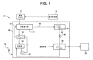
最初に図1を参照すると、本発明の例示的な実施形態により構成したターボ機械システムをその全体を参照符号2で示している。この図示した例示的な実施形態では、ターボ機械システム2は、ランキンサイクルベースシステムであり、蒸気タービン8に作動連結されたボイラ6を含む。図1にさらに示すように、蒸気タービン8は、熱交換器18を介して熱回収システム14に作動結合された復水器10のような関連する廃熱源を含む。当然ながら、蒸気タービン8は、それに限定されないが、発電電動機、排熱回収ボイラからの排気のような複数の付加的廃熱源を含む。以下にさらに詳しく説明するように、熱回収システム14は、冷却システム又は蒸気吸収機械22の形態を取る。蒸気吸収機械22は、本発明の1つの態様によると、復水器10からの廃棄熱を使用冷却媒体に移行させて、例えば冷却塔28のような外部冷却機械に対して冷却を行う。
Referring initially to FIG. 1, a turbomachine system constructed in accordance with an exemplary embodiment of the present invention is indicated generally by the reference numeral 2. In the illustrated exemplary embodiment, the turbomachine system 2 is a Rankine cycle based system and includes a boiler 6 operatively connected to a steam turbine 8. As further shown in FIG. 1, the steam turbine 8 includes an associated waste heat source, such as a
さらにこの図示した例示的な実施形態によると、蒸気吸収機械22は、熱交換器18、並びにポンプ35及び蒸発器38に流体連結された吸収器33を含む。蒸発器38は、膨張弁45を介して復水器42に流体連結される。復水器42は次に、廃熱源又は復水器10に流体連結されて、流体回路48を形成する。この構成の場合には、復水器10からの廃棄廃熱は、流体回路48を通って復水器42に流れる流体に伝達される。アンモニア又は同様のもののような冷却媒体は、復水器42を通って流れて、流体回路48を通って流れる流体から熱を抽出して冷却媒体を形成する。冷却媒体は、膨張弁45を通して蒸発器38に導かれる。蒸発器38上を流れる外気は、冷却塔28に流れる冷却空気流を形成する。この時点において、冷却媒体は、吸収器33を通って流れ、戻って熱交換器18を通って流れて、あらゆる残留熱が引出される。流体は、廃熱源又は復水器10に戻るように流れて、再びサイクルを開始する。このようにして、蒸気タービン8の作動に関連する廃熱を利用して、冷却媒体が生成される。冷却媒体は次に、例えば冷却塔に対して冷却を行うために利用される。廃熱の利用により、関連する発電システムによって発電される使用可能電力のおよそ1.0メガワットの増加が実現される。この出力増加は、発電プラント効率のおよそ0.1%の増大に相当する。
Further according to the illustrated exemplary embodiment, the
ここで、熱交換システムは本発明に従って変更することができることを理解されたい。つまり、熱回収システム14内に流す必要があるのは、復水器からの廃棄熱の一部分のみである。つまり、廃熱源10内に生じた付加的熱は、大気に廃棄するか又は冷却塔内の冷却水に廃棄することができる。また、冷却塔に対して冷却を行うことに加えて、冷却媒体は、圧縮機入力として用いる冷却作用を生じさせるために或いは関連する構造体に対して冷却を行うために使用することができる。
Here, it should be understood that the heat exchange system can be modified in accordance with the present invention. That is, only a portion of the waste heat from the condenser needs to flow through the
全体として、本明細書は最良の形態を含む幾つかの実施例を使用して、本発明を開示し、さらにあらゆる装置又はシステムを製作しかつ使用しまたあらゆる組込み方法を実行することを含む本発明の当業者による実施を可能にする。本発明の特許性がある技術的範囲は、特許請求の範囲によって定まり、また当業者が想到するその他の実施例を含むことができる。そのようなその他の実施例は、それらが特許請求の範囲の文言と相違しない構造的要素を有するか又はそれらが特許請求の範囲の文言と本質的でない相違を有する均等な構造的要素を含む場合には、特許請求の範囲の技術的範囲内に属することになることを意図している。 Overall, this specification uses several embodiments, including the best mode, to disclose the present invention and to further include making and using any device or system and performing any embedded method. Allows implementation of the invention by those skilled in the art. The patentable scope of the invention is defined by the claims, and may include other examples that occur to those skilled in the art. Such other embodiments may have structural elements that do not differ from the language of the claims, or they contain equivalent structural elements that have non-essential differences from the language of the claims. Is intended to fall within the scope of the appended claims.
2 ターボ機械システム
6 ボイラ(蒸気発生器)
8 蒸気タービン
10 廃熱源復水器
14 熱回収システム
18 熱交換器
22 冷却システム
23 蒸気吸収機械(VAM)
28 冷却塔
33 吸収器
35 ポンプ
38 蒸発器
42 復水器
45 膨張弁
48 流体回路
54 冷却塔
2 Turbomachine system 6 Boiler (steam generator)
8
28
Claims (10)
前記廃熱源に作動連結された冷却システムと
を含み、前記冷却システムが前記廃熱源から廃棄熱を抽出して冷却媒体を形成することができる、熱回収システム。 Waste heat source,
And a cooling system operatively connected to the waste heat source, wherein the cooling system can extract waste heat from the waste heat source to form a cooling medium.
ターボ機械と作動的に関連する廃熱源を通して熱交換媒体を流すステップと、
前記廃熱源から前記熱交換媒体内に熱を抽出するステップと、
前記熱交換媒体を冷却システムまで導くステップと、
前記熱交換媒体から熱を抽出して冷却媒体を生成するステップと
を含む方法。 A method of operating a heat recovery system comprising:
Flowing a heat exchange medium through a waste heat source operatively associated with the turbomachine;
Extracting heat from the waste heat source into the heat exchange medium;
Directing the heat exchange medium to a cooling system;
Extracting heat from the heat exchange medium to produce a cooling medium.
Applications Claiming Priority (1)
| Application Number | Priority Date | Filing Date | Title |
|---|---|---|---|
| US12/183,596 US8037703B2 (en) | 2008-07-31 | 2008-07-31 | Heat recovery system for a turbomachine and method of operating a heat recovery steam system for a turbomachine |
Publications (2)
| Publication Number | Publication Date |
|---|---|
| JP2010038536A true JP2010038536A (en) | 2010-02-18 |
| JP2010038536A5 JP2010038536A5 (en) | 2012-08-30 |
Family
ID=41528292
Family Applications (1)
| Application Number | Title | Priority Date | Filing Date |
|---|---|---|---|
| JP2009172616A Withdrawn JP2010038536A (en) | 2008-07-31 | 2009-07-24 | Heat recovery system for turbomachine, and method of operating heat recovery steam system for turbomachine |
Country Status (4)
| Country | Link |
|---|---|
| US (1) | US8037703B2 (en) |
| JP (1) | JP2010038536A (en) |
| CN (1) | CN101638999A (en) |
| DE (1) | DE102009026302A1 (en) |
Cited By (1)
| Publication number | Priority date | Publication date | Assignee | Title |
|---|---|---|---|---|
| WO2011105456A1 (en) | 2010-02-24 | 2011-09-01 | 日本特殊陶業株式会社 | Plug cap |
Families Citing this family (7)
| Publication number | Priority date | Publication date | Assignee | Title |
|---|---|---|---|---|
| EP2751499B1 (en) | 2011-09-02 | 2019-11-27 | Carrier Corporation | Refrigeration system and refrigeration method providing heat recovery |
| WO2014134748A1 (en) * | 2013-03-04 | 2014-09-12 | Li Huayu | Cogeneration type ii absorption heat pump |
| US20150372214A1 (en) * | 2014-06-24 | 2015-12-24 | General Electric Company | Cooled cooling air system having thermoelectric generator |
| CN104964474B (en) * | 2015-07-14 | 2017-07-07 | 国家电网公司 | A kind of cooling system of the utilizing waste heat for refrigeration of utilization generator motor |
| US10428798B2 (en) * | 2015-10-22 | 2019-10-01 | Australian Wind Technologies Pty Ltd | Wind turbine power storage and regeneration |
| EP3394395B1 (en) | 2015-12-21 | 2024-04-24 | Mathers Hydraulics Technologies Pty Ltd | Hydraulic machine with chamfered ring |
| EP3592952B1 (en) | 2017-03-06 | 2022-05-11 | Mathers Hydraulics Technologies Pty Ltd | Hydraulic machine with stepped roller vane and fluid power system including hydraulic machine with starter motor capability |
Citations (4)
| Publication number | Priority date | Publication date | Assignee | Title |
|---|---|---|---|---|
| JPH08226309A (en) * | 1994-09-27 | 1996-09-03 | Babcock & Wilcox Co:The | Ammonia absorption type refrigerating cycle for combination cycle type power plant |
| JP2001050045A (en) * | 1999-08-05 | 2001-02-23 | Stream:Kk | Cogeneration system for molding machine |
| JP2002089994A (en) * | 2000-09-19 | 2002-03-27 | Kawasaki Thermal Engineering Co Ltd | Absorption type water cooling and heating device utilizing waste heat |
| JP2004233030A (en) * | 2002-12-02 | 2004-08-19 | Denso Corp | Cooling device |
Family Cites Families (17)
| Publication number | Priority date | Publication date | Assignee | Title |
|---|---|---|---|---|
| US3423078A (en) * | 1966-03-17 | 1969-01-21 | Gen Electric | Combined jet and direct air condenser |
| US3831667A (en) * | 1971-02-04 | 1974-08-27 | Westinghouse Electric Corp | Combination wet and dry cooling system for a steam turbine |
| US3796045A (en) * | 1971-07-15 | 1974-03-12 | Turbo Dev Inc | Method and apparatus for increasing power output and/or thermal efficiency of a gas turbine power plant |
| JPS592836B2 (en) * | 1979-02-23 | 1984-01-20 | 富士電機株式会社 | Direct contact multi-stage pressure condensing equipment |
| US4223529A (en) * | 1979-08-03 | 1980-09-23 | General Electric Company | Combined cycle power plant with pressurized fluidized bed combustor |
| US4379485A (en) * | 1981-04-09 | 1983-04-12 | Foster Wheeler Energy Corporation | Wet/dry steam condenser |
| JPS59189265A (en) * | 1983-04-13 | 1984-10-26 | 株式会社日立製作所 | Triple effect absorption type refrigerator |
| US4655975A (en) * | 1986-01-27 | 1987-04-07 | The Dow Chemical Company | Solid chelating poly(carboxylate and/or sulfonate)peroxyhydrate bleaches |
| FI86578C (en) * | 1990-07-04 | 1992-09-10 | Ahlstroem Oy | Method and apparatus for cooling hot gases |
| JPH08100606A (en) * | 1994-09-30 | 1996-04-16 | Hitachi Ltd | Rankine cycle generating system and its operation method |
| US5787970A (en) * | 1994-12-06 | 1998-08-04 | Larinoff; Michael W. | Air-cooled vacuum steam condenser with mixed flow bundle |
| US6058695A (en) * | 1998-04-20 | 2000-05-09 | General Electric Co. | Gas turbine inlet air cooling method for combined cycle power plants |
| US6170263B1 (en) * | 1999-05-13 | 2001-01-09 | General Electric Co. | Method and apparatus for converting low grade heat to cooling load in an integrated gasification system |
| JP3716188B2 (en) * | 2001-04-10 | 2005-11-16 | 三菱重工業株式会社 | Gas turbine combined plant |
| DE10214183C1 (en) * | 2002-03-28 | 2003-05-08 | Siemens Ag | Drive mechanism, for refrigeration, has absorption refrigeration machine connected to steam turbine, operated by steam extracted from turbine, preferably from low pressure part of turbine |
| NO321817B1 (en) * | 2003-11-06 | 2006-07-10 | Sargas As | Wastewater treatment plants |
| US7367177B2 (en) * | 2004-12-14 | 2008-05-06 | Siemens Power Generation, Inc. | Combined cycle power plant with auxiliary air-cooled condenser |
-
2008
- 2008-07-31 US US12/183,596 patent/US8037703B2/en not_active Expired - Fee Related
-
2009
- 2009-07-24 JP JP2009172616A patent/JP2010038536A/en not_active Withdrawn
- 2009-07-30 CN CN200910159232A patent/CN101638999A/en active Pending
- 2009-07-31 DE DE102009026302A patent/DE102009026302A1/en not_active Withdrawn
Patent Citations (4)
| Publication number | Priority date | Publication date | Assignee | Title |
|---|---|---|---|---|
| JPH08226309A (en) * | 1994-09-27 | 1996-09-03 | Babcock & Wilcox Co:The | Ammonia absorption type refrigerating cycle for combination cycle type power plant |
| JP2001050045A (en) * | 1999-08-05 | 2001-02-23 | Stream:Kk | Cogeneration system for molding machine |
| JP2002089994A (en) * | 2000-09-19 | 2002-03-27 | Kawasaki Thermal Engineering Co Ltd | Absorption type water cooling and heating device utilizing waste heat |
| JP2004233030A (en) * | 2002-12-02 | 2004-08-19 | Denso Corp | Cooling device |
Cited By (1)
| Publication number | Priority date | Publication date | Assignee | Title |
|---|---|---|---|---|
| WO2011105456A1 (en) | 2010-02-24 | 2011-09-01 | 日本特殊陶業株式会社 | Plug cap |
Also Published As
| Publication number | Publication date |
|---|---|
| CN101638999A (en) | 2010-02-03 |
| DE102009026302A1 (en) | 2010-02-18 |
| US8037703B2 (en) | 2011-10-18 |
| US20100024444A1 (en) | 2010-02-04 |
Similar Documents
| Publication | Publication Date | Title |
|---|---|---|
| JP2010038536A (en) | Heat recovery system for turbomachine, and method of operating heat recovery steam system for turbomachine | |
| US8359824B2 (en) | Heat recovery steam generator for a combined cycle power plant | |
| US20110088399A1 (en) | Combined Cycle Power Plant Including A Refrigeration Cycle | |
| JP2011106459A (en) | Combined cycle power plant with integrated organic rankine cycle device | |
| JP5916053B2 (en) | System with feed water heater that extracts heat from a low pressure steam turbine | |
| JP2011080464A5 (en) | ||
| US9038391B2 (en) | System and method for recovery of waste heat from dual heat sources | |
| JP2007032568A (en) | Combined cycle power generation plant | |
| JP2009299682A (en) | System for recovering waste heat generated by auxiliary system of turbo machine | |
| JP2011085133A (en) | Reheat gas turbine | |
| EP2294298A1 (en) | Combined cycle power plant | |
| JP5325038B2 (en) | System and method applied to combined cycle power plant or Rankine cycle power plant using air-cooled steam condenser | |
| JP2010038157A (en) | Heat recovery system | |
| JP2010038536A5 (en) | ||
| JP2010038160A (en) | System and method for use in combined or rankine cycle power plant | |
| JP6243700B2 (en) | Combined cycle power plant with absorption heat converter | |
| JP2014047657A (en) | Moisture utilizing gas turbine system | |
| JP6382127B2 (en) | Heat exchanger, energy recovery device, and ship | |
| RU2409746C2 (en) | Steam-gas plant with steam turbine drive of compressor and regenerative gas turbine | |
| JPWO2012114367A1 (en) | Solar-powered gas turbine system | |
| JP2013140001A (en) | Power generating unit comprising condensed water recovery device | |
| JP2002129907A (en) | Gland sealing steam system of steam turbine | |
| CN213711133U (en) | Back pressure type ORC combined heat and power generation system | |
| JP5525233B2 (en) | Reduction of diluted nitrogen compressor power using a vapor absorption chiller. | |
| RU2686541C1 (en) | Steam-gas plant |
Legal Events
| Date | Code | Title | Description |
|---|---|---|---|
| A521 | Request for written amendment filed |
Free format text: JAPANESE INTERMEDIATE CODE: A523 Effective date: 20120717 |
|
| A621 | Written request for application examination |
Free format text: JAPANESE INTERMEDIATE CODE: A621 Effective date: 20120717 |
|
| A977 | Report on retrieval |
Free format text: JAPANESE INTERMEDIATE CODE: A971007 Effective date: 20130513 |
|
| A131 | Notification of reasons for refusal |
Free format text: JAPANESE INTERMEDIATE CODE: A131 Effective date: 20130521 |
|
| A761 | Written withdrawal of application |
Free format text: JAPANESE INTERMEDIATE CODE: A761 Effective date: 20130527 |
|
| A072 | Dismissal of procedure [no reply to invitation to correct request for examination] |
Free format text: JAPANESE INTERMEDIATE CODE: A072 Effective date: 20130910 |