JP2011085133A - Reheat gas turbine - Google Patents
Reheat gas turbine Download PDFInfo
- Publication number
- JP2011085133A JP2011085133A JP2010224449A JP2010224449A JP2011085133A JP 2011085133 A JP2011085133 A JP 2011085133A JP 2010224449 A JP2010224449 A JP 2010224449A JP 2010224449 A JP2010224449 A JP 2010224449A JP 2011085133 A JP2011085133 A JP 2011085133A
- Authority
- JP
- Japan
- Prior art keywords
- gas turbine
- steam
- energy
- boiler
- compressor
- Prior art date
- Legal status (The legal status is an assumption and is not a legal conclusion. Google has not performed a legal analysis and makes no representation as to the accuracy of the status listed.)
- Withdrawn
Links
Images

Classifications
-
- F—MECHANICAL ENGINEERING; LIGHTING; HEATING; WEAPONS; BLASTING
- F02—COMBUSTION ENGINES; HOT-GAS OR COMBUSTION-PRODUCT ENGINE PLANTS
- F02C—GAS-TURBINE PLANTS; AIR INTAKES FOR JET-PROPULSION PLANTS; CONTROLLING FUEL SUPPLY IN AIR-BREATHING JET-PROPULSION PLANTS
- F02C6/00—Plural gas-turbine plants; Combinations of gas-turbine plants with other apparatus; Adaptations of gas- turbine plants for special use
- F02C6/003—Gas-turbine plants with heaters between turbine stages
-
- F—MECHANICAL ENGINEERING; LIGHTING; HEATING; WEAPONS; BLASTING
- F01—MACHINES OR ENGINES IN GENERAL; ENGINE PLANTS IN GENERAL; STEAM ENGINES
- F01K—STEAM ENGINE PLANTS; STEAM ACCUMULATORS; ENGINE PLANTS NOT OTHERWISE PROVIDED FOR; ENGINES USING SPECIAL WORKING FLUIDS OR CYCLES
- F01K23/00—Plants characterised by more than one engine delivering power external to the plant, the engines being driven by different fluids
- F01K23/02—Plants characterised by more than one engine delivering power external to the plant, the engines being driven by different fluids the engine cycles being thermally coupled
- F01K23/06—Plants characterised by more than one engine delivering power external to the plant, the engines being driven by different fluids the engine cycles being thermally coupled combustion heat from one cycle heating the fluid in another cycle
- F01K23/10—Plants characterised by more than one engine delivering power external to the plant, the engines being driven by different fluids the engine cycles being thermally coupled combustion heat from one cycle heating the fluid in another cycle with exhaust fluid of one cycle heating the fluid in another cycle
-
- F—MECHANICAL ENGINEERING; LIGHTING; HEATING; WEAPONS; BLASTING
- F01—MACHINES OR ENGINES IN GENERAL; ENGINE PLANTS IN GENERAL; STEAM ENGINES
- F01K—STEAM ENGINE PLANTS; STEAM ACCUMULATORS; ENGINE PLANTS NOT OTHERWISE PROVIDED FOR; ENGINES USING SPECIAL WORKING FLUIDS OR CYCLES
- F01K7/00—Steam engine plants characterised by the use of specific types of engine; Plants or engines characterised by their use of special steam systems, cycles or processes; Control means specially adapted for such systems, cycles or processes; Use of withdrawn or exhaust steam for feed-water heating
- F01K7/06—Steam engine plants characterised by the use of specific types of engine; Plants or engines characterised by their use of special steam systems, cycles or processes; Control means specially adapted for such systems, cycles or processes; Use of withdrawn or exhaust steam for feed-water heating the engines being of multiple-inlet-pressure type
-
- F—MECHANICAL ENGINEERING; LIGHTING; HEATING; WEAPONS; BLASTING
- F02—COMBUSTION ENGINES; HOT-GAS OR COMBUSTION-PRODUCT ENGINE PLANTS
- F02C—GAS-TURBINE PLANTS; AIR INTAKES FOR JET-PROPULSION PLANTS; CONTROLLING FUEL SUPPLY IN AIR-BREATHING JET-PROPULSION PLANTS
- F02C7/00—Features, components parts, details or accessories, not provided for in, or of interest apart form groups F02C1/00 - F02C6/00; Air intakes for jet-propulsion plants
- F02C7/08—Heating air supply before combustion, e.g. by exhaust gases
-
- Y—GENERAL TAGGING OF NEW TECHNOLOGICAL DEVELOPMENTS; GENERAL TAGGING OF CROSS-SECTIONAL TECHNOLOGIES SPANNING OVER SEVERAL SECTIONS OF THE IPC; TECHNICAL SUBJECTS COVERED BY FORMER USPC CROSS-REFERENCE ART COLLECTIONS [XRACs] AND DIGESTS
- Y02—TECHNOLOGIES OR APPLICATIONS FOR MITIGATION OR ADAPTATION AGAINST CLIMATE CHANGE
- Y02E—REDUCTION OF GREENHOUSE GAS [GHG] EMISSIONS, RELATED TO ENERGY GENERATION, TRANSMISSION OR DISTRIBUTION
- Y02E20/00—Combustion technologies with mitigation potential
- Y02E20/14—Combined heat and power generation [CHP]
-
- Y—GENERAL TAGGING OF NEW TECHNOLOGICAL DEVELOPMENTS; GENERAL TAGGING OF CROSS-SECTIONAL TECHNOLOGIES SPANNING OVER SEVERAL SECTIONS OF THE IPC; TECHNICAL SUBJECTS COVERED BY FORMER USPC CROSS-REFERENCE ART COLLECTIONS [XRACs] AND DIGESTS
- Y02—TECHNOLOGIES OR APPLICATIONS FOR MITIGATION OR ADAPTATION AGAINST CLIMATE CHANGE
- Y02E—REDUCTION OF GREENHOUSE GAS [GHG] EMISSIONS, RELATED TO ENERGY GENERATION, TRANSMISSION OR DISTRIBUTION
- Y02E20/00—Combustion technologies with mitigation potential
- Y02E20/16—Combined cycle power plant [CCPP], or combined cycle gas turbine [CCGT]
Abstract
Description
本発明は、化石燃料燃焼式ガスタービンエンジンに関し、より具体的には、一次化石燃料エネルギー源に加えて二次フリー又は廃エネルギー源を利用してシステムの全体変換効率を向上させることに関する。 The present invention relates to fossil fuel combustion gas turbine engines, and more particularly to improving the overall conversion efficiency of a system using a secondary free or waste energy source in addition to a primary fossil fuel energy source.
ガスタービンエンジンでは、空気が、圧縮機内で加圧されかつ燃焼器内で燃料と混合されて高温の燃焼ガスを発生し、この高温燃焼ガスが下流方向に膨張装置に流れ、膨張装置が、高温燃焼ガスからエネルギーを取出す。最新式ガスタービンエンジンの燃焼器からの高温ガス流の温度は、非常に高く、一般的に2500°Fを充分に超える。そのような温度は、例えばノズル又はベーン(固定している)、ブレード又はバケット(回転する)、及びそれらの間におけるホイールスペースのようなタービン部品の製造に使用される高性能合金の融点に匹敵するか又は該融点よりもさらに高い。これらの部品は一般に、高温ガス通路(HGP)構成部品と呼ばれる。冷却がない場合には、最新式ガスタービンエンジンの第1段を構成する翼形部は数秒以内で融解することになると考えられたい。ガスタービンエンジン内のHGP構成部品を冷却するために使用する空気は一般的に、圧縮機吐出口又は中間段位置から抽出され、従って燃焼及びタービン膨張プロセスで使用されず、それに対応してガスタービンエンジンの全体効率を低下させる。冷却空気流は、「チャージ可能」空気流と呼ばれ、その量は、圧縮機からタービンに送られる加圧空気の温度によって制御される。一般的に、膨張通路における冷却式タービン部品がより下流にあればあるほど、圧縮機における冷却媒体抽出ポイントがより上流にあることになる。タービンを通って膨張する高温ガスとの使用済み冷却空気の混合は、混合及び冷却損失に起因して更なる仕事損失の発生源となる。 In a gas turbine engine, air is pressurized in a compressor and mixed with fuel in a combustor to generate hot combustion gases that flow downstream to the expansion device, which is then hot Extract energy from combustion gases. The temperature of the hot gas stream from the combustor of a modern gas turbine engine is very high, typically well over 2500 ° F. Such temperatures are comparable to the melting points of high performance alloys used in the manufacture of turbine components such as nozzles or vanes (fixed), blades or buckets (rotating), and wheel spaces between them. Or higher than the melting point. These parts are commonly referred to as hot gas path (HGP) components. In the absence of cooling, it should be considered that the airfoil that forms the first stage of a modern gas turbine engine will melt within seconds. The air used to cool the HGP components in the gas turbine engine is typically extracted from the compressor discharge or intermediate stage position and is therefore not used in the combustion and turbine expansion processes, correspondingly in the gas turbine Reduce the overall efficiency of the engine. The cooling air flow is referred to as a “chargeable” air flow, the amount of which is controlled by the temperature of the pressurized air sent from the compressor to the turbine. In general, the more downstream the cooled turbine component in the expansion passage, the more upstream the coolant extraction point in the compressor. Mixing spent cooling air with hot gas expanding through the turbine is a source of further work loss due to mixing and cooling losses.
一般的に、燃焼器内で燃焼させる燃料の発熱量によるガスタービンへのエネルギー入力は、燃料自体及び/又は圧縮機吐出口からの燃焼空気の温度を高めることによって減少させることができる。燃焼器内で燃焼させる燃料の量のその後の減少は、燃料及び/又は燃焼空気の温度における前述の上昇を達成するためにフリー/廃エネルギー源が利用可能である場合には、ガスタービン効率の増大として反映される。発電において利用される最新式産業用つまり高出力ガスタービンでは、排熱回収ボイラ給水を使用する燃料ガス性能加熱(例えば、365°F又はそれ以上までの)は、確立された手法である。理論上は確かに実施可能であるが、同様な方法で圧縮機吐出空気を加熱することは、極めて高い吐出空気温度(例えば、最新式Fクラスタービンではほぼ800°F)及び非常に精密に組込まれたタービン構造のために、実行可能ではない。 In general, the energy input to the gas turbine due to the heating value of the fuel combusted in the combustor can be reduced by increasing the temperature of the combustion air from the fuel itself and / or the compressor outlet. Subsequent reductions in the amount of fuel combusted in the combustor may result in gas turbine efficiency if free / waste energy sources are available to achieve the aforementioned increase in fuel and / or combustion air temperature. Reflected as an increase. In modern industrial or high power gas turbines utilized in power generation, fuel gas performance heating (eg up to 365 ° F. or higher) using exhaust heat recovery boiler feedwater is an established approach. Although theoretically certainly feasible, heating the compressor discharge air in a similar manner incorporates very high discharge air temperatures (eg, nearly 800 ° F. for modern F class turbines) and very precisely It is not feasible because of the turbine structure.
従来と同様に、例えば集中太陽熱発電(CSP)用途では、フリー又は廃エネルギーが、蒸気タービンにおける蒸気発生及び電力生産のために利用される。例えば、ガス及び蒸気タービン複合サイクル(CC)発電プラントでは、ガスタービン排気からの廃エネルギーを利用して、蒸気タービンにおける付加的膨張及び発電のための蒸気を排熱回収ボイラ(HRSG)内で発生させる。温度−エントロピー表面上にガス及び蒸気タービンを表す基礎熱力学サイクルつまりそれぞれブレイトン及びランキンサイクルの相対的位置のために、一般に前者は、「トッピング」サイクルと呼ばれ、また後者は、「ボトミング」サイクルと呼ばれる。他のシステムでは、CC発電プラントのHRSGにおける蒸気発生は、個々のボイラセクションにおいて(フリー)太陽エネルギーを利用することによって補足される。いずれにしても、CC発電プラントのボトミング蒸気サイクルにおいてフリー又は廃エネルギーが利用される。 As is conventional, for example, in concentrated solar power (CSP) applications, free or waste energy is utilized for steam generation and power production in steam turbines. For example, in gas and steam turbine combined cycle (CC) power plants, waste energy from gas turbine exhaust is used to generate steam for additional expansion and power generation in the steam turbine in a heat recovery steam generator (HRSG). Let Due to the relative position of the basic thermodynamic cycle representing the gas and steam turbine on the temperature-entropy surface, namely the Brayton and Rankine cycle respectively, the former is commonly referred to as the “topping” cycle and the latter is referred to as the “bottoming” cycle. Called. In other systems, steam generation in the HRSG of a CC power plant is supplemented by utilizing (free) solar energy in individual boiler sections. In any case, free or waste energy is utilized in the bottoming steam cycle of the CC power plant.
本発明の態様によると、ガスタービンシステムを提供する。本ガスタービンシステムは、圧縮機と、膨張装置と、圧縮機及び膨張装置間に配置された燃焼器と、圧縮機及び膨張装置間に配置されたボイラと、チャージ可能空気を含みかつボイラと熱連通した導管と、ボイラに結合された外部フリー熱源とを含むことができる。 According to an aspect of the invention, a gas turbine system is provided. The gas turbine system includes a compressor, an expansion device, a combustor disposed between the compressor and the expansion device, a boiler disposed between the compressor and the expansion device, chargeable air and the boiler and heat. A communicating conduit and an external free heat source coupled to the boiler may be included.
本発明の別の態様によると、ガスタービンシステムを提供する。本ガスタービンシステムは、圧縮機と、膨張装置と、圧縮機及び膨張装置間に配置されかつ燃料供給を有する燃焼器と、圧縮機及び膨張装置間に配置された第1のボイラと、チャージ可能空気を含みかつ第1のボイラと熱連通しており、該第1のボイラがチャージ可能空気に熱を与える導管と、第1のボイラに結合された外部フリー熱源と、燃料供給に熱エネルギーを与える第2のボイラとを含むことができる。 According to another aspect of the invention, a gas turbine system is provided. The gas turbine system includes a compressor, an expansion device, a combustor disposed between the compressor and the expansion device and having a fuel supply, a first boiler disposed between the compressor and the expansion device, and chargeable. Containing air and in thermal communication with the first boiler, the first boiler providing heat to the chargeable air, an external free heat source coupled to the first boiler, and thermal energy to the fuel supply And a second boiler to be provided.
本発明のさらに別の態様によると、方法を提供する。本方法は、燃焼器を有するガスタービンにおいて第1のエネルギー流を発生させるステップと、ガスタービンにおいて第2のエネルギー流を発生させるステップと、ガスタービンの外部のエネルギー源において第3のエネルギー流を発生させるステップと、第3のエネルギー流を第1のエネルギー流と混合して、該第1のエネルギー流及び第2のエネルギー流における熱エネルギーを増大させるステップとを含むことができる。 According to yet another aspect of the invention, a method is provided. The method includes generating a first energy flow in a gas turbine having a combustor, generating a second energy flow in the gas turbine, and generating a third energy flow in an energy source external to the gas turbine. Generating and mixing a third energy stream with the first energy stream to increase thermal energy in the first energy stream and the second energy stream.
これらの及びその他の利点並びに特徴は、図面と関連させて行った以下の説明から一層明らかになるであろう。 These and other advantages and features will become more apparent from the following description taken in conjunction with the drawings.
本発明は、本明細書と共に提出した特許請求の範囲において具体的に指摘しかつ明確に特許請求している。本発明の前述の及びその他の特徴並びに利点は、添付図面と関連させて行った以下の詳細な説明から明らかである。 The invention is specifically pointed out and distinctly claimed in the claims appended hereto. The foregoing and other features and advantages of the present invention will be apparent from the following detailed description taken in conjunction with the accompanying drawings.
詳細な説明は、図面を参照しながら実施例によって、本発明の実施形態をその利点及び特徴と共に説明する。 The detailed description explains embodiments of the invention, together with advantages and features, by way of example with reference to the drawings.
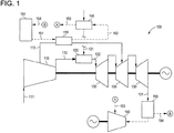
図1は、例示的な外部再熱ガスタービンシステム100を示している。本明細書にさらに説明するように、CC発電プラントのトッピングガスサイクルにおいてフリー又は廃エネルギーを利用することが可能である場合には、2つの別個のメカニズム、つまり1)よく知られておりかつこの技術に関するあらゆる基本の教本内で述べられている再熱効果によるトッピング(ガスタービン)サイクル効率の向上、及び2)HRSGに供給するガスタービン排気ガス流のエネルギー(有用性)の増大によるボトミング(蒸気タービン)サイクル効率の向上の組合せによって、全体システムの効率における増加がより大きなものになることを基礎熱力学は明記している。
FIG. 1 illustrates an exemplary external reheat
本明細書に説明するように、外部再熱ガスタービンサイクルでは、蒸気は、フリー又は排熱源を利用するボイラ150内で発生させることができかつシステム100の様々な部分に供給することができる。これに関連して、「フリー」及び「廃」という表現は、前述のエネルギーを発生させるのに、付加的化石燃料(資本支出により購入した)を全く利用しないことを意味している。実施例は、無コストで世界中どこでも容易に入手可能である太陽エネルギー、及びそうでなければ大気中への放出により廃棄されることになる内燃エンジンからの排気ガスのような既存プロセスの副産物としてのエネルギーのような再生可能エネルギー源である。本明細書では、ボイラという用語は、熱源を利用して水を蒸気に変換するする熱交換器を記述するために、その最も一般的な意味で使用している。前述の効果を達成するための特定の熱機械的及びその他の設計態様は、本発明にとって重要なものではない。本明細書にさらに説明するように、ボイラ150は、フリー太陽エネルギー又は製鋼所の溶融スラグ生成物などの排熱源のような蒸気発生のための様々な熱源を含むことができる。「フリー」及び「廃」という用語は、互換的に使用されかつガスタービンの外部で供給された熱源を記述する用語であることを理解されたい。ボイラ150内で発生した蒸気による「フリー」熱源(例えば、集中太陽熱発電プラント、太陽熱コレクタフィールド、溶融スラグからの排熱回収など)は、チャージ可能冷却流の温度を高める。蒸気はまた、ガスタービン燃料を加熱するように使用し、それによって燃焼器内で消費される燃料の量を減少させかつガスタービン効率を向上させることができる。ガスタービンのHGPに流入する高温のチャージ可能流れによって生じた再熱効果は、システム100の効率及び出力を高める。
As described herein, in an external reheat gas turbine cycle, steam can be generated in a
図1に示す例示的な実施形態では、本システム100は、大気111を受けかつ加圧空気112及び複数の流れの形態とすることができるチャージ可能空気流113を発生させるタービン圧縮機110を含む。圧縮機は、膨張装置130に作動結合される。加圧空気112は、燃焼器120のためのものとして生成され、またチャージ可能冷却空気113は、ガスタービン膨張装置130のHGP構成部品のためのものとして生成される。燃焼器は、圧縮機110及び膨張装置130間に配置されて、圧縮機110から加圧空気112を受けかつ高温生成ガス122を膨張装置130に供給する。燃焼器120はまた、燃料供給121を受ける。本システム100はさらに、複合サイクル(CC)構成に従ったガスタービン排気流131を含む。CC構成では、システム100はさらに、排気流131のエネルギーを回収しかつ蒸気タービン160を駆動する蒸気を発生させるHRSG155を含むことができる。蒸気タービン160は、低圧、中圧及び高圧セクション並びにHRSG155で再使用するための排出蒸気を復水させる復水器を含むことができる。排気流131を再使用するために多くの付加的構成を実装することができ、また説明の目的でHRSG155及び蒸気タービン160を図示している。図1に示す例示的な実施形態では、空気加熱器135が、圧縮機110及び膨張装置130間に配置され、かつそれら圧縮機110及び膨張装置130に対して作動結合される。チャージ可能空気113は、圧縮機110から空気加熱器135を通ってかつ外部配管又は他の好適な導管を介して膨張装置130に流れる。供給導管151及び戻り導管152が、それぞれボイラ150及び空気加熱器135間並びに空気加熱器135及び燃料加熱器140間に配置される。燃料加熱器140は、ボイラ150及び空気加熱器135間で戻り導管152上に配置される。燃料加熱器からの使用済み蒸気153は、さらに有用なシャフト動力生成のためにその圧力及び温度に見合った位置で流入させるように蒸気タービン160に送られる。ボイラ150には、蒸気生成のためにHRSG155の低圧(LP)エコノマイザ吐出口から水154が供給される。
In the exemplary embodiment shown in FIG. 1, the
図1に示す例示的な実施形態では、圧縮機110におけるその発生源でのチャージ可能冷却空気流113は一般的に、約400°F〜650°Fである。本明細書に説明するように、フリー又は排熱は、チャージ可能空気流113を加熱して本システム100の全体効率を向上させるために利用される。具体的には、圧縮機110の段から抽出したチャージ可能冷却空気113は、ガスタービン膨張装置130セクションに流入させる前に、ボイラ150においてフリー又は排熱源(例えば、製鋼所からの溶融スラグ又は太陽熱)を利用することによって発生させた蒸気を使用して望ましい温度(例えば、800°F〜1000°F)に加熱される。従って、フリーエネルギーは、膨張の残りの間に余分のエネルギーを発生させるために、膨張しているガス内に導入する(つまり、そのエンタルピーを増加させる)ことができる。例えば、最新式Fクラス165MW高出力産業用ガスタービンでは、計算によると、チャージ可能冷却流の200°F(300°F)上昇に対して800kW(1300kW)までのGT出力の追加を示している。この結果は、例えば集中太陽熱発電を利用して600psiaでボイラ150において発生させた1050°F過熱蒸気を使用することによって達成することができる。さらに、ガスタービン排気流131の温度における上昇は、4°F〜7°Fであり、この温度上昇は、2x1CC構成つまり2つのガスタービン及び1つの蒸気タービン構成において、それぞれ1200kW〜2000kWの付加的ボトミングサイクル蒸気タービン出力に相当する。従って、上記したこの例示的なシステム100では、2x1構成(公称510MW)における最新式FクラスガスタービンシステムのCC出力への最終的影響は、それぞれチャージ可能冷却流における200°F及び350°Fの上昇に対して2.75MW〜4.5MWである。
In the exemplary embodiment shown in FIG. 1, the chargeable
図1に示す例示的な実施形態では、冷却空気加熱器135からの使用済み蒸気は、燃料加熱器140においてガスタービン燃料121を加熱するために利用することができる。例えば、冷却空気加熱器131からの使用済み蒸気は、既存性能の燃料加熱器(これは、HRSG155からの中圧(IP)エコノマイザ給水を利用する)を補足して、例えば365°Fから440°Fに燃料温度を上昇させるために利用することができる。加えて、冷却空気加熱器131からの使用済み蒸気は、全体燃料加熱を代わりに行なうように使用して、それによってHRSG155における蒸気発生及び蒸気タービン160における出力生成を増加させることができる。さらに、燃料加熱器140からの使用済み蒸気153は、その圧力及び温度に見合った好適な位置で流入させるように蒸気タービン160に送ることができる。例えば、ボイラ150内で発生させた600psiaかつ1050°Fの蒸気151を利用することによって空気加熱器135内で達成することができるチャージ可能冷却流における350°Fの温度上昇の場合には、空気加熱器135からの使用済み蒸気152を燃料加熱器140内で利用して燃料供給121の温度を365°Fから440°Fに上昇させた後に、550°Fまでの蒸気は、LP蒸気タービンセクションのボウルでの流入に利用可能である。この結果により、別の5MW〜6MWの付加的シャフト出力生成を得ることができる。加えて、燃焼器への入口における75°Fのより高い燃料温度の利点は、正味CC効率における約0.15パーセント(%)である。従って、ボイラ150内で発生させた600psiaかつ1050°Fの蒸気151によって空気加熱器135内で達成することができるチャージ可能冷却流における350°Fの温度上昇の場合には、9.5MW〜10.5MW(正味CC効率における0.9%以上に相当する)の性能向上及び正味CC効率における1%以上の性能向上が、公称510MW2x1CC発電プラントシステムにおいて実施可能である。さらに、空気加熱器135からの使用済み蒸気152を燃料加熱器140内で利用して、全体燃料加熱つまりパイプライン温度から365°F又はそれ以上まで加熱するようにする場合には、更なる効率向上が実施可能となり、このことは、前述の燃料加熱を達成するためにHRSGから予め分流させた排気ガスエネルギーを元に戻すことによって、HRSG155でのより多くの蒸気発生及び蒸気タービン160でのより大きい出力生成を生じさせることを可能にする。
In the exemplary embodiment shown in FIG. 1, spent steam from cooling
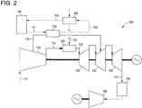
図2に示す例示的な実施形態では、蒸気は、商業的に入手可能な熱伝導流体と置き換えられる。従って、ボイラ150は、熱交換器150となり、この熱交換器150内において、前述の流体の温度は、フリー又は排熱源からの熱を吸収することによって高められる。ここでも同様に、前述の効果を達成するための特定の熱機械的な及びその他の設計態様は、本発明にとって重要なものではない。本発明が必要とする温度つまり900°F又はそれ以上で実現可能に利用することができる熱伝導流体の存在の下では、この実施形態は、フリー/排熱源とチャージ可能な空気113及び燃料供給121との間における熱伝導媒体として蒸気を利用する好ましい実施形態と完全に等価なものとなる。現在では、商業的に入手可能な熱伝導流体の温度性能は、ほぼ700°Fが限界である。このことは、現時点では熱伝導流体を使用する本発明の実施可能な実装を実行可能でないものにしているが、より高い温度範囲を有する熱伝導流体の将来の有用性は、それら熱伝導流体を蒸気に代わる実行可能な代替物にするであろう。言うまでもなく、図2における別の実施形態では、前述のパラグラフに記載したような蒸気タービン160における付加的発電機会は、存在しない。
In the exemplary embodiment shown in FIG. 2, the vapor is replaced with a commercially available heat transfer fluid. Accordingly, the
図3は、例示的な実施形態による、ガスタービンにおいて外部再熱する方法300のフローチャートを示している。例示的な実施形態では、圧縮機における中間段位置から抽出されかつ膨張装置(タービン)ケーシングに管輸送されたチャージ可能冷却空気は、再流入位置よりも前で加熱される。このプロセスは、ガスタービンシステムへのフリーエネルギーの導入を構成し、このフリーエネルギーは、冷却空気再流入位置の下流での残りの膨張の間に有用なシャフト仕事に転換される。ブロック310において、本システム100、200は、第1のエネルギー流を発生させる。例示的な実施形態では、一次高温ガス流及びそれに対応するチャージ可能空気流113は、第1のエネルギー流として生成される。ブロック320において、本システム100、200は、第2のエネルギー流を発生させる。例示的な実施形態では、第2のエネルギー流は、排気流131とすることができる。ブロック330において、本システム100、200は、ガスタービンの外部の熱源で第3のエネルギー流を発生させる。例示的な実施形態では、第3のエネルギー流は、フリー又は廃エネルギー源による外部熱交換器150によって発生された蒸気の形態になった熱である。ブロック340において、本システム100、200は、第1及び第3のエネルギー流を混合する。例示的な実施形態では、第3のエネルギー流は、本明細書に説明するように、チャージ可能空気流113と関連する温度を上昇させる手段となる。その結果、排気流131と関連する温度もまた、第1及び第2のエネルギー流の混合に対応して上昇する。例示的な実施形態では、第1のエネルギー流は、圧縮機110からの加圧空気112であり、また第3のエネルギー流は、加圧空気と関連する温度を上昇させる。第1のエネルギー流はまた、燃焼器120のための燃料供給121における熱とすることができ、また第3のエネルギー流は、燃料流121と関連する温度を上昇させる。
FIG. 3 shows a flowchart of a
本明細書に説明した例示的な実施形態は、あらゆる複合サイクルにおける本来の構成及び熱回収構成の両方に対して改良をもたらすものであり、ここでは、トッピングサイクル作動流体が、入手可能なフリーエネルギーで直接加熱されると同時に、トッピングサイクルの加圧作動流体を加熱するために回収されるのではなくて該トッピングサイクルに与えられた付加エネルギーにより高い温度を有するあらゆる残りのトッピングサイクルエンジン排気エネルギーを回収しかつ利用するボトミングサイクルが、フリーエネルギーを形成する。技術的な効果には、システム100の変換効率の向上が含まれる。この変換効率の向上は、2つのステップにおいて、つまり1)ガスタービンにおいて(最終のタービン段において膨張仕事を行なわせること)及び2)向上したガスタービンによるボトミングサイクル(つまり、蒸気タービン)において、有用な出力を発生させる熱をシステム100に与えることにより生じる。
The exemplary embodiments described herein provide improvements over both the original and heat recovery configurations in any combined cycle, where the topping cycle working fluid is free energy available. The remaining topping cycle engine exhaust energy having a higher temperature due to the added energy given to the topping cycle rather than being recovered to heat the pressurized working fluid of the topping cycle at the same time. The bottoming cycle that is recovered and utilized forms free energy. Technical effects include improving the conversion efficiency of the
限られた数の実施形態に関してのみ本発明を詳細に説明してきたが、本発明がそのような開示した実施形態に限定されるものではないことは、容易に理解される筈である。むしろ、本発明は、これまで説明していないが本発明の技術思想及び技術的範囲に相応するあらゆる数の変形、変更、置換え又は均等な構成を組込むように改良することができる。さらに、本発明の様々な実施形態について説明してきたが、本発明の態様は説明した実施形態の一部のみを含むことができることを理解されたい。従って、本発明は、上記の説明によって限定されるものと見なすべきではなく、本発明は、特許請求の範囲の技術的範囲によってのみ限定される。 Although the present invention has been described in detail only with respect to a limited number of embodiments, it should be readily understood that the invention is not limited to such disclosed embodiments. Rather, the invention can be modified to incorporate any number of variations, alterations, substitutions or equivalent arrangements not heretofore described, but which are commensurate with the spirit and scope of the invention. Moreover, while various embodiments of the invention have been described, it is to be understood that aspects of the invention can include only some of the described embodiments. Accordingly, the invention is not to be seen as limited by the foregoing description, but is limited only by the scope of the claims.
100 外部再熱ガスタービンシステム
110 タービン圧縮機
111 大気
112 加圧空気
113 チャージ可能空気流
120 燃焼器
121 燃料供給
122 高温生成ガス
130 膨張装置
131 ガスタービン排気流
135 空気加熱器
140 燃料加熱器
150 ボイラ
151 供給導管
152 戻し導管
153 使用済み蒸気
154 水
155 HRSC
160 蒸気タービン
200 外部再熱ガスタービンシステム
100 External Reheat
160
Claims (10)
圧縮機(110)と、
膨張装置(130)と、
前記圧縮機(110)及び膨張装置(130)間に配置された燃焼器(120)と、
前記圧縮機(110)及び膨張装置(130)間に配置されたボイラ(150)と、
チャージ可能空気を含みかつ前記ボイラ(150)と熱連通した導管(151、152)と、
前記ボイラ(150)に結合された外部フリー熱源と
を含むシステム。 An external reheat gas turbine system (100) comprising:
A compressor (110);
An expansion device (130);
A combustor (120) disposed between the compressor (110) and an expansion device (130);
A boiler (150) disposed between the compressor (110) and the expansion device (130);
Conduits (151, 152) containing chargeable air and in thermal communication with the boiler (150);
An external free heat source coupled to the boiler (150).
Applications Claiming Priority (1)
| Application Number | Priority Date | Filing Date | Title |
|---|---|---|---|
| US12/580,399 US8281565B2 (en) | 2009-10-16 | 2009-10-16 | Reheat gas turbine |
Publications (2)
| Publication Number | Publication Date |
|---|---|
| JP2011085133A true JP2011085133A (en) | 2011-04-28 |
| JP2011085133A5 JP2011085133A5 (en) | 2013-11-21 |
Family
ID=43799010
Family Applications (1)
| Application Number | Title | Priority Date | Filing Date |
|---|---|---|---|
| JP2010224449A Withdrawn JP2011085133A (en) | 2009-10-16 | 2010-10-04 | Reheat gas turbine |
Country Status (5)
| Country | Link |
|---|---|
| US (1) | US8281565B2 (en) |
| JP (1) | JP2011085133A (en) |
| CN (1) | CN102042090A (en) |
| CH (1) | CH702103A8 (en) |
| DE (1) | DE102010037861A1 (en) |
Cited By (3)
| Publication number | Priority date | Publication date | Assignee | Title |
|---|---|---|---|---|
| JP2015052427A (en) * | 2013-09-06 | 2015-03-19 | 株式会社東芝 | Steam turbine plant |
| JP2016044569A (en) * | 2014-08-20 | 2016-04-04 | 株式会社東芝 | Gas turbine power plant |
| JP2018091323A (en) * | 2016-11-01 | 2018-06-14 | ゼネラル・エレクトリック・カンパニイ | Fuel heating system using steam and water in single fuel heat exchanger |
Families Citing this family (15)
| Publication number | Priority date | Publication date | Assignee | Title |
|---|---|---|---|---|
| US7770376B1 (en) * | 2006-01-21 | 2010-08-10 | Florida Turbine Technologies, Inc. | Dual heat exchanger power cycle |
| WO2011053925A2 (en) * | 2009-10-30 | 2011-05-05 | Qgen Ltd. | Control and solar power improvements of a concentrated solar power-enabled power plant |
| AU2010326107B2 (en) * | 2009-12-01 | 2016-02-25 | Areva Solar, Inc. | Utilizing steam and/or hot water generated using solar energy |
| ES2449706T3 (en) * | 2010-04-01 | 2014-03-20 | Alstom Technology Ltd | Procedure to increase the efficiency of a power plant installation equipped with a gas turbine, and a power plant installation for performing the procedure |
| WO2012120555A1 (en) * | 2011-03-07 | 2012-09-13 | 株式会社 日立製作所 | Solar heat utilization gas turbine system |
| CH705929A1 (en) * | 2011-12-22 | 2013-06-28 | Alstom Technology Ltd | A method of operating a combined cycle power plant. |
| US9169782B2 (en) * | 2012-01-04 | 2015-10-27 | General Electric Company | Turbine to operate at part-load |
| US20130205797A1 (en) * | 2012-02-14 | 2013-08-15 | General Electric Company | Fuel heating system for power plant |
| US20140060072A1 (en) * | 2012-09-04 | 2014-03-06 | General Electric Company | Method of starting a gas turbine system |
| US9074491B2 (en) | 2012-09-05 | 2015-07-07 | General Electric Company | Steam cycle system with thermoelectric generator |
| JP5896885B2 (en) * | 2012-11-13 | 2016-03-30 | 三菱日立パワーシステムズ株式会社 | Power generation system and method for operating power generation system |
| NL2011310C2 (en) | 2013-08-15 | 2014-09-29 | Ice Ind Properties B V | Fluid distributing apparatus. |
| NL2011309C2 (en) | 2013-08-15 | 2014-09-29 | Ice Ind Properties B V | Process to obtain a compressed gas. |
| US9500103B2 (en) | 2013-08-22 | 2016-11-22 | General Electric Company | Duct fired combined cycle system |
| CN106382161B (en) * | 2016-11-21 | 2018-01-19 | 西安交通大学 | A kind of multiple level efficient air turbine installation using hydrogen-rich fuel |
Family Cites Families (19)
| Publication number | Priority date | Publication date | Assignee | Title |
|---|---|---|---|---|
| DE1065666B (en) * | 1951-09-28 | 1959-09-17 | Power Jets (Research &. Development) Limited London | Combined gas turbine steam generator for the supply of both thermal energy and mechanical power |
| DE2553283A1 (en) * | 1975-11-27 | 1977-06-02 | Messerschmitt Boelkow Blohm | SOLAR THERMAL POWER PLANT |
| US4754607A (en) * | 1986-12-12 | 1988-07-05 | Allied-Signal Inc. | Power generating system |
| US4942736A (en) * | 1988-09-19 | 1990-07-24 | Ormat Inc. | Method of and apparatus for producing power from solar energy |
| JPH0476205A (en) | 1990-07-18 | 1992-03-11 | Toshiba Corp | Combined cycle electric power plant |
| US5417052A (en) * | 1993-11-05 | 1995-05-23 | Midwest Research Institute | Hybrid solar central receiver for combined cycle power plant |
| JP3530243B2 (en) | 1995-01-11 | 2004-05-24 | 三菱重工業株式会社 | Regenerative gas turbine combined cycle power generation method |
| JPH11270352A (en) * | 1998-03-24 | 1999-10-05 | Mitsubishi Heavy Ind Ltd | Intake air cooling type gas turbine power generating equipment and generation power plant using the power generating equipment |
| CA2269731C (en) * | 1998-04-28 | 2001-12-11 | Mitsubishi Heavy Industries, Ltd. | Combined cycle plant |
| JP2000027662A (en) | 1998-07-10 | 2000-01-25 | Mitsubishi Heavy Ind Ltd | Combined cycle plant using regenerative gas turbine |
| JP2000120447A (en) * | 1998-10-12 | 2000-04-25 | Toshiba Corp | Thermal power plant |
| US6145295A (en) * | 1998-11-23 | 2000-11-14 | Siemens Westinghouse Power Corporation | Combined cycle power plant having improved cooling and method of operation thereof |
| US6601391B2 (en) * | 2001-06-19 | 2003-08-05 | Geosol, Inc. | Heat recovery |
| JP3854156B2 (en) | 2002-01-15 | 2006-12-06 | 株式会社日立製作所 | Regenerative gas turbine combined cycle power generation system |
| US6666027B1 (en) * | 2002-07-15 | 2003-12-23 | General Electric Company | Turbine power generation systems and methods using off-gas fuels |
| US20050121532A1 (en) * | 2003-12-05 | 2005-06-09 | Reale Michael J. | System and method for district heating with intercooled gas turbine engine |
| JP4959156B2 (en) * | 2004-11-29 | 2012-06-20 | 三菱重工業株式会社 | Heat recovery equipment |
| US7287381B1 (en) * | 2005-10-05 | 2007-10-30 | Modular Energy Solutions, Ltd. | Power recovery and energy conversion systems and methods of using same |
| US20090235634A1 (en) * | 2008-03-24 | 2009-09-24 | General Electric Company | System for extending the turndown range of a turbomachine |
-
2009
- 2009-10-16 US US12/580,399 patent/US8281565B2/en not_active Expired - Fee Related
-
2010
- 2010-09-29 DE DE102010037861A patent/DE102010037861A1/en not_active Withdrawn
- 2010-10-04 JP JP2010224449A patent/JP2011085133A/en not_active Withdrawn
- 2010-10-11 CH CH01653/10A patent/CH702103A8/en not_active Application Discontinuation
- 2010-10-15 CN CN2010105222344A patent/CN102042090A/en active Pending
Cited By (4)
| Publication number | Priority date | Publication date | Assignee | Title |
|---|---|---|---|---|
| JP2015052427A (en) * | 2013-09-06 | 2015-03-19 | 株式会社東芝 | Steam turbine plant |
| JP2016044569A (en) * | 2014-08-20 | 2016-04-04 | 株式会社東芝 | Gas turbine power plant |
| JP2018091323A (en) * | 2016-11-01 | 2018-06-14 | ゼネラル・エレクトリック・カンパニイ | Fuel heating system using steam and water in single fuel heat exchanger |
| JP7051368B2 (en) | 2016-11-01 | 2022-04-11 | ゼネラル・エレクトリック・カンパニイ | Fuel heating system using steam and water in a single fuel heat exchanger |
Also Published As
| Publication number | Publication date |
|---|---|
| CN102042090A (en) | 2011-05-04 |
| CH702103A2 (en) | 2011-04-29 |
| US20110088404A1 (en) | 2011-04-21 |
| US8281565B2 (en) | 2012-10-09 |
| DE102010037861A1 (en) | 2011-04-21 |
| CH702103A8 (en) | 2011-07-15 |
Similar Documents
| Publication | Publication Date | Title |
|---|---|---|
| JP2011085133A (en) | Reheat gas turbine | |
| Carcasci et al. | Thermodynamic analysis of an Organic Rankine Cycle for waste heat recovery from an aeroderivative intercooled gas turbine | |
| JP4776729B2 (en) | Steam turbine plant and method for cooling intermediate pressure turbine thereof | |
| US20110113786A1 (en) | Combined cycle power plant with integrated organic rankine cycle device | |
| KR20100081279A (en) | Method for expanding compressor discharge bleed air | |
| JP2009299682A (en) | System for recovering waste heat generated by auxiliary system of turbo machine | |
| EP2535533A2 (en) | Asymmetrical combined cycle power plant | |
| US6244039B1 (en) | Combined cycle plant having a heat exchanger for compressed air | |
| JP2012132454A (en) | System and method for using gas turbine intercooler heat in bottoming steam cycle | |
| JP2001214759A (en) | Gas turbine combined cycle | |
| EP2604821B1 (en) | System and method for thermal control in a gas turbine engine | |
| Carapellucci et al. | Studying the effects of combining internal and external heat recovery on techno-economic performances of gas–steam power plants | |
| US8141336B1 (en) | Combined cycle power augmentation by efficient utilization of atomizing air energy | |
| Mohanty et al. | Performance analysis of a combined cycle gas turbine under varying operating conditions | |
| US10287922B2 (en) | Steam turbine plant, combined cycle plant provided with same, and method of operating steam turbine plant | |
| McDaniel et al. | A combined cycle power conversion system for the next generation nuclear power plant | |
| Kumar et al. | Performance evaluation of gas-steam combined cycle having transpiration cooled gas turbine | |
| Lebele-Alawa et al. | Improved design of a 25 MW Gas turbine plant using combined cycle application | |
| EP2752566B1 (en) | Gas turbine cooling system, and gas turbine cooling method | |
| US8869532B2 (en) | Steam turbine utilizing IP extraction flow for inner shell cooling | |
| JP4488787B2 (en) | Steam turbine plant and method for cooling intermediate pressure turbine thereof | |
| EP3318733B1 (en) | Feedwater bypass system for a desuperheater | |
| CA2983533C (en) | Combined cycle power generation | |
| JPH04124411A (en) | Steam turbine combine generator equipment | |
| RU2686541C1 (en) | Steam-gas plant |
Legal Events
| Date | Code | Title | Description |
|---|---|---|---|
| A521 | Written amendment |
Free format text: JAPANESE INTERMEDIATE CODE: A523 Effective date: 20131003 |
|
| A621 | Written request for application examination |
Free format text: JAPANESE INTERMEDIATE CODE: A621 Effective date: 20131003 |
|
| A761 | Written withdrawal of application |
Free format text: JAPANESE INTERMEDIATE CODE: A761 Effective date: 20131209 |