JP3854156B2 - Regenerative gas turbine combined cycle power generation system - Google Patents
Regenerative gas turbine combined cycle power generation system Download PDFInfo
- Publication number
- JP3854156B2 JP3854156B2 JP2002005910A JP2002005910A JP3854156B2 JP 3854156 B2 JP3854156 B2 JP 3854156B2 JP 2002005910 A JP2002005910 A JP 2002005910A JP 2002005910 A JP2002005910 A JP 2002005910A JP 3854156 B2 JP3854156 B2 JP 3854156B2
- Authority
- JP
- Japan
- Prior art keywords
- power generation
- gas turbine
- gas
- combined cycle
- generation system
- Prior art date
- Legal status (The legal status is an assumption and is not a legal conclusion. Google has not performed a legal analysis and makes no representation as to the accuracy of the status listed.)
- Expired - Fee Related
Links
Images


Classifications
-
- Y—GENERAL TAGGING OF NEW TECHNOLOGICAL DEVELOPMENTS; GENERAL TAGGING OF CROSS-SECTIONAL TECHNOLOGIES SPANNING OVER SEVERAL SECTIONS OF THE IPC; TECHNICAL SUBJECTS COVERED BY FORMER USPC CROSS-REFERENCE ART COLLECTIONS [XRACs] AND DIGESTS
- Y02—TECHNOLOGIES OR APPLICATIONS FOR MITIGATION OR ADAPTATION AGAINST CLIMATE CHANGE
- Y02E—REDUCTION OF GREENHOUSE GAS [GHG] EMISSIONS, RELATED TO ENERGY GENERATION, TRANSMISSION OR DISTRIBUTION
- Y02E20/00—Combustion technologies with mitigation potential
- Y02E20/16—Combined cycle power plant [CCPP], or combined cycle gas turbine [CCGT]
Description
【0001】
【発明の属する技術分野】
本発明は再生式ガスタービンと蒸気タービンサイクルとを用いた再生式ガスタービンコンバインドサイクル発電システムに関し、特に高い発電効率を達成するように改良した再生式ガスタービンコンバインドサイクル発電、及び、負荷遮断時などの緊急停止時におけるガスタービンのオーバースピードを防止する機能を備えた再生式ガスタービンに関するものである。
【0002】
【従来の技術】
燃焼によるエネルギーを原動機により動力または電気エネルギーに変換する主な方法として、ガスタービンによる方法と蒸気タービンによる方法がある。ガスタービンを用いる場合は、圧縮した空気を支燃剤として燃料を燃焼させ、それにより得られる高温高圧の燃焼ガスでガスタービンを駆動回転させる。一方、蒸気タービンでは、ボイラーで発生させた高温高圧の蒸気でタービンを駆動回転させる。ガスタービンの発電効率は蒸気タービンと同程度であるが、ガスタービンによる場合は600℃前後の高温排ガスが排出される。そこで、ガスタービンを用いて発電すると共に、ガスタービンからの高温排ガスの熱で蒸気を発生させ、この蒸気により蒸気タービンを用いて発電することによりプラント全体としての発電効率を高めたガスタービンコンバインド発電方式が開発され、広く実用に供されている。
【0003】
また、ガスタービンによる発電の改良型として、ガスタービンを駆動した後の高温排ガスとガスタービンの燃焼器に供給する圧縮空気を再生器で熱交換させることにより高温の圧縮空気とし、この高温圧縮空気を燃焼器に供給することにより、ガスタービンの燃料を低減してガスタービンの発電効率を向上させる再生式ガスタービンが知られている。
さらに、この再生式ガスタービンからの排ガスの熱で蒸気を発生させ、この蒸気により蒸気タービンを用いて発電することによりプラント全体としての発電効率を高めようとする再生式ガスタービンコンバインドサイクル発電方式が知られている。
【0004】
特開平8−189310号公報には、この再生式ガスタービンコンバインドサイクル発電方式の発電効率を向上させる目的で、燃焼器とガスタービンの間に高温高圧の燃焼ガス(約1450℃)を加熱源とするチューブ状の蒸気過熱器を設け、排熱回収ボイラーで発生させた300℃〜400℃の蒸気を導いて過熱し、得られた約600℃の過熱蒸気を蒸気タービンに供給する再生式ガスタービンコンバインドサイクル発電方式が提案されている。
【0005】
再生式ガスタービンでは燃焼用空気はその全量が再生器を経由して燃焼器に入る。このため、負荷遮断が発生した場合に急激に燃料を絞っても、燃焼用空気が大きな熱容量と内容積を持つ再生器で加熱されることにより、タービンへの大きな熱入力が一定時間維持される。そのため、ガスタービンがオーバースピードとなり破損する恐れがある。負荷遮断時におけるオーバースピードを防止するためにはタービンへの熱入力を急減させる必要があり、その方法としては、(1)燃焼用空気の一部について再生器をバイパスさせるバイパスバルブを設ける方式、(2)燃焼用空気の一部を大気に放出するための大気放出バルブを設けるなどの方法が知られている。
【0006】
また、従来の再生式ガスタービンコンバインドサイクル発電方式では、図1に示すように再生式ガスタービン51と蒸気タービンサイクル52が組み合わされ、再生器36のガスタービン排ガス後流に蒸気タービンサイクル52が配置されている。
【0007】
再生式ガスタービン51は、空気4を圧縮する圧縮機1、圧縮された空気4を加熱する熱回収装置の再生器36、加熱された燃焼用空気20、燃料5と燃焼用空気20を供給して燃焼させる燃焼器2、燃焼で発生した高温ガスの供給で駆動されるガスタービン3を有する。
【0008】
蒸気タービンサイクル52は、供給される蒸気で駆動される蒸気タービン16、蒸気タービン16から排気される蒸気を冷やして水にする復水器17、復水された水に加える補給水18、補給された水を送る給水ポンプ19、送られる水を加熱するところの排ガス28が流れる熱回収装置の低圧給水加熱器14、加熱した水を送る高圧給水ポンプ15、高圧給水ポンプ15より送られる加熱水を加熱する高圧給水加熱器11、高圧給水加熱器11より送られる高圧加熱水を水蒸気になるように加熱する高圧蒸気発生器10、高圧蒸気発生器10で発生した蒸気を過熱する高圧蒸気過熱器37、低圧給水加熱器14で加熱した加熱水の分流を加熱して水蒸気にする低圧蒸気発生器13、低圧蒸気発生器13で発生した蒸気を蒸気タービン16の中段に供給する前に過熱する低圧蒸気過熱器12を有する。なお、ガスタービン3からの排気ガス21は熱回収装置の上流側に導入され、排気ガス28は熱回収装置の下流側から排出される。
【0009】
この方式は従来のガスタービンコンバインド発電方式より発電効率を向上することができるが、再生器36において多量の熱が排ガス21から回収されるので、再生器36の出口側の排ガス温度が低下する。そのため、高圧蒸気過熱器37において高温高圧の過熱蒸気を得ることができず、蒸気タービンサイクル52の効率は低下する。そのため、満足のいく発電効率までは得られていない。
【0010】
特開平8−189310号公報で提案されている技術は、上記の再生式ガスタービンコンバインドサイクル発電方式を改良して高温高圧の過熱蒸気を得ることにより、さらに発電効率を高めようとする技術である。この技術では高温高圧の過熱蒸気を得るため、図2に示すように燃焼器2からの超高温の燃焼ガスと蒸気発生器31からの蒸気を超高温蒸気過熱器33で熱交換し、得られた高温の過熱蒸気で蒸気タービン16を駆動している。しかし、1450℃前後の超高温燃焼ガスを熱源とする超高温蒸気過熱器33が必要であり、材料、設置スペース、蒸気サイクルにトラブルが発生した場合の健全性保証などに技術課題がある。
【0011】
また、ガスタービンの負荷を遮断する際に燃焼器2の運転も止めて温度を下げるが、超高温蒸気過熱器33に蓄熱されている熱容量がガスタービンの入り口のガス流路に加わるため、負荷遮断時にガスタービンがオーバースピードにいたるポテンシャルが増加するという課題もある。
【0012】
さらに、従来の再生式ガスタービンでは、負荷遮断時におけるガスタービンのオーバースピード防止のためには、燃焼用空気の再生器バイパスや大気放出用としての大容量のバルブが必要となり、急速動作を保証することが困難であるという課題がある。
【0013】
【発明が解決しようとする課題】
本発明は、上記の問題に鑑み、超高温蒸気過熱器を必要とすることなく、従来のガスタービンコンバインドサイクル発電方式より大幅に高い発電効率を達成できる再生式ガスタービンコンバインドサイクル発電システムを提供することである。
【0014】
また、それに加え、負荷遮断時などの緊急停止時におけるガスタービンのオーバースピードを防止するためのバイパスバルブや大気放出バルブが不要で、それらの負荷を軽減できる機能を備えた再生式ガスタービンコンバインドサイクル発電システムを提供することである。
【0015】
【課題を解決するための手段】
本発明は、支燃焼ガスを圧縮する圧縮機と、圧縮された支燃焼ガスと燃料の供給により燃焼して高温ガスを発生する燃焼器と、高温ガスの供給で駆動されるガスタービンと、ガスタービンから排出される排気ガスから熱を回収する熱回収装置と、排気ガスが流れる熱回収装置のガス流路に設けられ、かつ燃焼器に供給される圧縮後の支燃焼ガスを加熱する再生器と、排気ガスの流れから見て再生器の下流側に位置するようにガス流路に設けられ、かつ蒸気を過熱する高圧蒸気過熱器と、過熱された蒸気の供給で駆動される蒸気タービンとを有する再生式ガスタービンコンバインドサイクル発電システムにあって、再生器の上流側と下流側との中間にあたる中間位置または中間位置から上流側に位置するところに蒸気をより高温に再過熱する再高圧蒸気過熱器を設けたことを特徴とする。
【0016】
また、本発明は、上記の再生式ガスタービンコンバインドサイクル発電システムにあって、再生器で加熱された支燃焼ガスを燃焼器に供給される前に急冷することを特徴とする。
【0017】
【発明の実施の形態】
以下、本発明の実施例を図面を参照して説明する。
【0018】
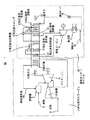
図4は、本発明の実施例を示す再生式ガスタービンコンバインドサイクル発電システムのシステム構成図である。図1および図2(従来例)と共通するところは、共通の符号を付して説明を省略し、異なるところを主に説明する。
【0019】
図4に示すように本実施例のガス系統は、以下のように構成されている。
圧縮機1の吸気口上流に設けた水噴霧器22により粒径5〜20μmの微細水滴を圧縮機吸込み空気4に噴霧する。この微細水滴は圧縮機1の吸気口上流でその一部が蒸発して空気温度を低下させる。この温度の低下した空気と未蒸発の微細水滴は圧縮機1に吸込まれ、微細水滴は圧縮過程でさらに蒸発して空気温度を低下させる。この圧縮機1の出口から抽気した圧縮空気を高圧蒸気過熱器8の排ガス下流側に配置した低温側の再生器7で予熱し、さらに、再高圧蒸気過熱器8の排ガス上流側に配置した高温側の再生器6で加熱する。この加熱した圧縮空気を空気急冷用噴霧装置25を経て、燃焼器2に燃焼用空気20として導入している。
【0020】
燃焼器2には燃料5と燃焼用空気20(支燃焼ガス)を供給し、燃料5を燃焼用空気20(支燃焼ガス)により燃焼して1,300℃程度の燃焼ガス(高温ガス)を発生させる。この燃焼ガス(高温ガス)をガスタービン3に供給して膨張させることにより動力を取り出し、その動力の一部で圧縮機1を駆動し、残りの動力で発電機を回して発電する。
【0021】
ガスタービン3からの排ガス流路(熱回収装置)には、高温側の再生器6、再高圧蒸気過熱器8、低温側の再生器7、高圧蒸気過熱器9、高圧蒸気発生器10、高圧給水加熱器11、低圧蒸気過熱器12、低圧蒸気発生器13、低圧給水加熱器14の順で直列に熱交換器類を配置している。ガスタービン3から排気される600℃程度の排ガス21はこれらの熱交換器類で排ガス温度100℃程度まで熱回収された後、煙突から大気に放出される。
【0022】
また、本実施例における水・蒸気系統はいわゆる非再熱複圧の蒸気タービンサイクルであり、以下のように構成している。
【0023】
補給水18及び復水器17からの給水を給水ポンプ19で昇圧し、低温給水加熱器14で昇温した低圧給水の一部を分岐して低圧蒸気発生器13に供給している。低圧蒸気発生器13で発生した低圧蒸気は、過熱のための低圧蒸気過熱器12を経て蒸気タービン16に供給され、発電に供される。
【0024】
低温給水加熱器14で昇温した残りの低圧給水は、さらに昇温するための高圧給水加熱器11を経て高圧蒸気発生器10に供給される。この高圧蒸気発生器10で発生した蒸気は、低温側の再生器7の排ガス下流側に配置した高圧蒸気過熱器9で予熱した後、低温側の再生器7の排ガス上流側に配置した再高圧蒸気過熱器8で高温まで過熱され、蒸気タービン16に供給される。
【0025】
蒸気タービン16で仕事をした後の排蒸気は復水器17で水に戻され、補給水18と合流して給水ポンプ19で昇圧され、再び低圧給水加熱器14に供給される。
【0026】
圧縮機1の吸気ダクトには水噴霧装置22を設け、噴霧用水23を噴霧水供給弁24を経て水噴霧器22に供給している。水噴霧装置22としては、一流体ノズル、二流体ノズルなどを複数個配置して構成可能である。なお、二流体ノズルの場合には噴霧用水のほかに圧縮空気源が必要であるが、この圧縮空気源としては圧縮機1からの抽気空気や別置きの圧縮機からの空気を使用することができる。
【0027】
なお、噴霧用水の供給元は図示していないが、別に設けた給水系統から常温の純水を供給する方式、高圧給水加熱器11から分岐した高温高圧水を供給する方式など、種々の方式を採用可能である。また、圧縮機1への水噴霧位置は本実施例で示した圧縮機1の入口空気に限られるものではなく、圧縮機1の中の圧縮過程の空気に水噴霧しても良い。
【0028】
さらに、本実施例における空気急冷用水噴霧系統は、以下のように構成している。
【0029】
空気急冷用水噴霧装置25は高温側の再生器6の空気出口に配置され、この空気急冷用水噴霧装置25は空気急冷用噴霧水供給弁26を介して蓄圧貯水槽27と配管で接続されている。蓄圧貯水槽27には噴霧用水が空気等のガスにより加圧された状態で蓄えられている。空気急冷用噴霧水供給弁26は通常運転時には閉じられている。負荷遮断等のガスタービンオーバースピードの恐れある事象が発生した場合には、空気急冷用噴霧水供給弁26が急速開されることにより、空気急冷用水噴霧装置25に噴霧用水が供給され、5〜50μmの微細水滴が圧縮空気中に噴霧される構成としている。
【0030】
上記実施例により、超高温蒸気過熱器を必要とすることなく、従来のガスタービンコンバインドサイクル発電方式より大幅に高い発電効率を達成できるのである。
【0031】
すなわち、再生式ガスタービンの再生器を少なくとも2つの高温側の再生器6及び低温側の再生器7で構成し、再生式ガスタービンからの排ガス流路(熱回収装置)の上流側に高温側の再生器6を、その高温側の再生器6の下流側に低温側の再生器7を、高温側の再生器6と低温側の再生器7の間の中間位置に蒸気タービンサイクルを構成する最も温度、圧力の高い再高圧蒸気過熱器8が置かれるように直列状に配置した構成を有している。
【0032】
高温側の再生器6及び再高圧蒸気過熱器8で高温のガスタービン排ガスから高温まで熱回収し、温度の低下したガスタービン排ガスで低温側の再生器7による燃焼用空気の予熱、さらには給水加熱及び蒸発を行うことにより、高温の燃焼用空気と高温の過熱蒸気を同時に得ることができる。これにより、発電効率の高い再生式ガスタービンコンバインドサイクル発電システムを実現できる。
【0033】
なお、従来の再生式ガスタービンサイクル発電システムを詳細に検討した結果、ガスタービンの圧力比、燃焼温度、蒸気サイクルの蒸気条件などにより多少は変化するが、代表的な再生式ガスタービンコンバインドサイクル発電システムでは従来のコンバインドサイクル発電システムより発生蒸気量が少なく、蒸気過熱器での回収熱量は再生器における回収熱量の1/4程度であることを見出した。そのため、蒸気過熱器を再生器よりガスタービン排ガス流路の上流側に配置してもガスタービン排ガスの温度低下は小さく、再生器出口の燃焼用空気を高温まで加熱することができることを見出し、このような試行.検討を重ねて本発明を完成させるに至ったのである。
【0034】
次に高い発電効率を達成する作用効果について、本実施例と従来技術とを比較して説明する。
【0035】
図1に示した従来の再生式ガスタービンコンバインドサイクル発電方式、および、図5に示した本発明の再生式ガスタービンコンバインドサイクル発電方式の発電効率と主なプロセス量について、合理的、かつ、主要構成機器の性能等を同一条件として解析した結果を、表1に比較して示す。
【0036】
【表1】

なお、表1には、本発明の従来の再生式ガスタービンコンバインドサイクル発電方式を「従来再生CC」、本発明の再生式ガスタービンコンバインドサイクル発電方式で水噴霧装置22を設けない場合を「本発明(水噴霧なし)」、水噴霧装置22を設けた場合を「本発明(水噴霧あり)」と表記している。
【0038】
表1に示すように、燃焼用空気20の温度を560℃とした場合の蒸気タービン16入口の高圧蒸気温度は、従来再生CCでは430℃程度が上限となるのに対して本発明(水噴霧無し)では538℃程度まで高めることができる。そのため、蒸気タービンの効率が高まるので蒸気タービン発電量が増加しており、ガスタービン発電量と合わせた総合発電量が増加している。これにより、本発明(水噴霧なし)は従来再生CCより高い発電効率を得られることがわかる。
【0039】
さらに表1に示すように、空気4の流量の約1重量%の微細水滴を水噴霧装置22により噴霧した本発明(水噴霧あり)では、本発明(水噴霧なし)に比較して圧縮機1の所要動力が減少し、ガスタービン発電量が大きく増加している。本発明(水噴霧あり)では、図3を用いて後述するように再生器回収熱量の増加により蒸気タービンサイクルへの排ガス熱量が減少するため、蒸気タービンの発電量は本発明(水噴霧無し)より減少するが、それ以上にガスタービンの発電量が大きく、総合発電量は増加している。これにより、本発明(水噴霧あり)は従来再生CCはもとより本発明(水噴霧なし)よりさらに高い発電効率を得られることがわかる。
【0040】
高い発電効率について、図3を引用してさらに詳しく述べる。
【0041】
図3は、本発明の再生式ガスタービンコンバインドサイクル発電システムにおける水噴霧効果を説明するためのエネルギーフロー図を示すものである。このエネルギーフロー図は、ガスタービン、蒸気タービン、熱交換器などの代表的な性能を用いてシステム解析した結果に基づいている。
【0042】
図4中の数値は、低位発熱量(LHV)基準の燃料入熱を100とした場合の各部エネルギー割合を示しており、発電出力が発電効率に相当する。また、同図中の( )内の数値は水噴霧を行わない場合の各部エネルギー割合を示している。
(1).図3に示すように、水噴霧した場合は圧縮機の中間冷却効果により、圧縮機動力が低下する。
(2).圧縮機出口の圧縮空気の熱エネルギーは、圧縮機動力が低下する効果と噴霧水の蒸発による潜熱ロスにより、水噴霧しない場合より大きく低下する。すなわち、圧縮機出口の空気温度が低下する。一方、この温度の低下した圧縮空気が再生器に導入されるので、圧縮空気によるガスタービン排ガスからの回収熱量が大幅に増加する。そのため、圧縮機出口の熱量と再生器での回収熱量の和である燃焼器に入る圧縮空気の熱量はほとんど変化せず、タービン入熱及びタービン動力も水噴霧しない時とほとんど同じとなる。
(3).前記(1)により圧縮機動力は低下し、かつ、前記(2)によりタービン動力はほとんど変化しないため、水噴霧によりガスタービン(GT)出力は大幅に増加する。
(4).一方、再生器回収熱量の増加により蒸気サイクルの熱源であるタービン排ガス熱量が減少するため、蒸気タービン出力は低下する。しかし、再生式ガスタービンコンバインドサイクル発電システムでは従来のコンバインドサイクル発電システムに比べてガスタービン出力に対する蒸気タービン出力の割合が小さいため、蒸気タービン出力の低下量も小さい。
(5).したがって、水噴霧によるガスタービン出力の増加量が蒸気タービン出力の低下量を上回り、プラント効率は向上する。
【0043】
次に負荷遮断時のガスタービンオーバースピードを抑制する作用効果について説明する。
【0044】
本発明(水噴霧なし)の通常運転時には、表1に示すようにタービン3の軸出力326MWのうち167MWは圧縮機1を駆動するために消費され、残りの159MWで発電機を回して154MWの電力を発生している。これにより、エネルギーバランスが保たれ、ガスタービン(タービン3と圧縮機1)は定格回転数で回転している。
【0045】
負荷遮断が発生すると発電機の駆動に消費される動力がほぼゼロになり、そのまま放置すれば余った動力により回転数が急速に増加してオーバースピードに至り、破損する。シンプルサイクルのガスタービンでは負荷遮断の発生直後に燃料を絞れば、ガスタービン3への入熱は圧縮機1からの圧縮機空気だけとなる。そのため、ガスタービン3の軸動力<圧縮機1の消費動力となり、回転数は減少に向かう。
【0046】
しかし、本発明で用いている再生式ガスタービンでは、圧縮空気が再生器を経由してガスタービンに供給されており、かつ、再生器は大きな熱容量を持っている。そのため、本実施例(水噴霧なし)の例では、負荷遮断の発生直後に燃料を遮断しても、熱容量の大きな再生器で加熱された500℃以上の高温の圧縮空気がガスタービンへ供給され、ガスタービン3で発生する軸動力が圧縮機1の消費動力を上回る状態が継続する。圧縮機1の消費動力を上回った動力(以下、余剰動力)によりガスタービンの回転数は上昇に向かい、そのまま放置すれば、オーバースピードに至る可能性がある。
【0047】
これを防止するため本実施例では、負荷遮断の発生直後に燃料を絞る又は遮断すると同時に空気急冷用噴霧水供給弁26を開して、高温側の再生器6の出口空気配管に設置した空気急冷用水噴霧装置25から水量12.5kg/sの微細水滴を圧縮空気中に噴霧する。燃料を遮断した直後の高温再生器6出口の圧縮空気温度は約547℃、流量は約380kg/sである。
【0048】
噴霧された水量12.5kg/sの微細水滴は上記の圧縮空気の熱を奪ってその全量が蒸発し、蒸気と圧縮空気の混合気体の温度を約447℃に下げ、その流量は392.5kg/sに増加する。この温度の低下した混合気体によりタービン3は駆動されるが、その軸出力は圧縮機1の消費動力と程度にまで低下する。そのため、ガスタービンの回転数が上昇することはなく、ガスタービンのオーバースピードを防止することができる。
【0049】
また、燃料の遮断及び空気急冷用水噴霧によりタービン3の排ガス21の温度は130℃〜140℃程度まで低下するので、この排ガス21によって高温再生器6は冷却され、高温再生器6出口の圧縮空気の温度も徐々に低下する。したがって、噴霧する水量は負荷遮断直後から徐々に減少させてよい。
【0050】
次に図5に示される他の実施例について説明する。
【0051】
図4に示す実施例と共通するところは、共通の符号を付して説明を省略し、異なるところを主に説明する。
【0052】
すなわち、タービン3からの排ガス流路の最上流部に、高温側の再生器6と再高圧蒸気過熱器8を並列に配置している。この高温側の再生器6と再高圧蒸気過熱器8を出た排ガスを合流させ、その合流後の排ガス流路に、低温側の再生器7、高圧蒸気過熱器9、高圧蒸気発生器10、高圧給水加熱器11、低圧蒸気過熱器12、低圧蒸気発生器13、低圧給水加熱器14の順で直列に熱交換器類を配置している。
【0053】
このように配置することにより、高温側の再生器6の圧縮空気及び再高圧蒸気過熱器8の蒸気は、タービン3からの高温の排ガス21で最初に加熱されるので、高い温度の燃焼用空気20及び高い温度の高圧蒸気を得ることができる。
【0054】
したがって、図4に示す実施例と同様に、高い発電効率を得ることが可能となる。
【0055】
【発明の効果】
以上説明したように本発明によれば、超高温蒸気過熱器を用いることなく、発電効率の高い再生式ガスタービンコンバインドサイクル発電システムを実現できる。
【図面の簡単な説明】
【図1】従来例の再生式ガスタービンコンバインドサイクル発電システムのシステム構成図。
【図2】従来例の再生式ガスタービンコンバインドサイクル発電システムのシステム構成図。
【図3】本発明の実施例に係る再生式ガスタービンコンバインドサイクル発電システムのエネルギーフロー説明図。
【図4】本発明の実施例に係る再生式ガスタービンコンバインドサイクル発電システムのシステム構成図。
【図5】本発明の他の実施例に係る再生式ガスタービンコンバインドサイクル発電システムのシステム構成図。
【符号の説明】
1…圧縮機、2…燃焼器、3…タービン、4…空気、5…燃料、6…高温側の再生器、7…低温側の再生器、8…再高温蒸気過熱器、9…高温蒸気過熱器、10…高圧蒸気発生器、11…高圧給水過熱器、12…低圧蒸気過熱器、13…低圧蒸気発生器、14…低圧給水過熱器、15…高圧給水ポンプ、16…蒸気タービン、17…復水器、18…補給水、19…給水ポンプ、20…燃焼用空気、21…排ガス、22…水噴霧装置、23…噴霧用水、24…噴霧水供給弁、25…空気急冷用水噴霧装置、26…空気急冷用噴霧水供給弁、27…蓄圧貯水槽、28…排ガス、31…蒸気発生器、32…給水加熱器、33…超高温蒸気過熱器、36…再生器、37…高圧蒸気過熱器、51…再生式ガスタービン、52…蒸気タービンサイクル。[0001]
BACKGROUND OF THE INVENTION
The present invention relates to a regenerative gas turbine combined cycle power generation system using a regenerative gas turbine and a steam turbine cycle, and more particularly to a regenerative gas turbine combined cycle power generation improved so as to achieve high power generation efficiency and when a load is interrupted. The present invention relates to a regenerative gas turbine having a function of preventing overspeed of the gas turbine during an emergency stop.
[0002]
[Prior art]
There are a gas turbine method and a steam turbine method as main methods for converting energy from combustion into power or electric energy by a prime mover. When a gas turbine is used, fuel is combusted using compressed air as a combustion support agent, and the gas turbine is driven and rotated by a high-temperature and high-pressure combustion gas obtained thereby. On the other hand, in a steam turbine, the turbine is driven and rotated by high-temperature and high-pressure steam generated by a boiler. The power generation efficiency of the gas turbine is similar to that of the steam turbine, but in the case of using a gas turbine, high-temperature exhaust gas around 600 ° C. is discharged. Therefore, gas turbine combined power generation that generates power using a gas turbine, generates steam with the heat of high-temperature exhaust gas from the gas turbine, and generates power using the steam turbine with this steam to increase the power generation efficiency of the entire plant. A method has been developed and is widely used in practice.
[0003]
Further, as an improved type of power generation by the gas turbine, the high-temperature exhaust gas after driving the gas turbine and the compressed air to be supplied to the combustor of the gas turbine are heat-exchanged by a regenerator so that the high-temperature compressed air is used. There is known a regenerative gas turbine that supplies fuel to a combustor to reduce the fuel of the gas turbine and improve the power generation efficiency of the gas turbine.
Furthermore, there is a regenerative gas turbine combined cycle power generation system that generates steam with the heat of exhaust gas from the regenerative gas turbine and generates power using the steam turbine to increase the power generation efficiency of the entire plant. Are known.
[0004]
In JP-A-8-189310, for the purpose of improving the power generation efficiency of this regenerative gas turbine combined cycle power generation system, a high-temperature and high-pressure combustion gas (about 1450 ° C.) is used as a heating source between the combustor and the gas turbine. Regenerative gas turbine having a tube-shaped steam superheater that conducts, superheats the steam at 300 ° C. to 400 ° C. generated by the exhaust heat recovery boiler, and supplies the obtained superheated steam at about 600 ° C. to the steam turbine A combined cycle power generation method has been proposed.
[0005]
In a regenerative gas turbine, the entire amount of combustion air enters the combustor via the regenerator. For this reason, even if the fuel is suddenly throttled when a load interruption occurs, the combustion air is heated by a regenerator having a large heat capacity and internal volume, so that a large heat input to the turbine is maintained for a certain period of time. . Therefore, the gas turbine may be overspeeded and damaged. In order to prevent overspeed when the load is interrupted, it is necessary to rapidly reduce the heat input to the turbine. (1) A method of providing a bypass valve that bypasses the regenerator for a part of the combustion air, (2) A method of providing an atmospheric release valve for releasing a part of combustion air to the atmosphere is known.
[0006]
Further, in the conventional regenerative gas turbine combined cycle power generation system, as shown in FIG. 1, the
[0007]
The
[0008]
The
[0009]
Although this method can improve the power generation efficiency over the conventional gas turbine combined power generation method, since a large amount of heat is recovered from the
[0010]
The technique proposed in Japanese Patent Laid-Open No. 8-189310 is a technique for improving the above-described regenerative gas turbine combined cycle power generation system to obtain high-temperature and high-pressure superheated steam, thereby further improving the power generation efficiency. . In this technique, in order to obtain high-temperature and high-pressure superheated steam, as shown in FIG. 2, the superheated combustion gas from the
[0011]
Further, when the load of the gas turbine is cut off, the operation of the
[0012]
In addition, conventional regenerative gas turbines require a large-capacity valve for bypassing the combustion air regenerator and releasing air to prevent overspeeding of the gas turbine when the load is interrupted, ensuring rapid operation. There is a problem that it is difficult to do.
[0013]
[Problems to be solved by the invention]
In view of the above problems, the present invention provides a regenerative gas turbine combined cycle power generation system that can achieve significantly higher power generation efficiency than a conventional gas turbine combined cycle power generation method without requiring an ultra-high temperature steam superheater. That is.
[0014]
In addition, there is no need for a bypass valve or air release valve to prevent overspeeding of the gas turbine during an emergency stop such as when the load is cut off, and the regenerative gas turbine combined cycle has a function that can reduce those loads. It is to provide a power generation system.
[0015]
[Means for Solving the Problems]
The present invention relates to a compressor for compressing a support combustion gas, a combustor for generating high temperature gas by combustion by supply of compressed support combustion gas and fuel, a gas turbine driven by supply of high temperature gas, and a gas A heat recovery device that recovers heat from exhaust gas discharged from the turbine, and a regenerator that is provided in a gas flow path of the heat recovery device through which the exhaust gas flows and that heats the support combustion gas after compression supplied to the combustor When steam driven provided in the gas flow path as viewed from the exhaust gas flow located downstream of the regenerator, and the steam and over-heat the high pressure steam superheater, with supply of the over heated steam in the regenerative gas turbine combined cycle power generation system having a turbine, re excessive heat to a higher temperature steam at located upstream from the intermediate corresponding to the intermediate position or middle position between the upstream side and the downstream side of the regenerator Re Characterized in that a steam superheater.
[0016]
The present invention is also characterized in that in the above-described regenerative gas turbine combined cycle power generation system, the support combustion gas heated by the regenerator is rapidly cooled before being supplied to the combustor.
[0017]
DETAILED DESCRIPTION OF THE INVENTION
Embodiments of the present invention will be described below with reference to the drawings.
[0018]
FIG. 4 is a system configuration diagram of a regenerative gas turbine combined cycle power generation system showing an embodiment of the present invention. The parts common to FIGS. 1 and 2 (conventional example) are denoted by the same reference numerals, description thereof is omitted, and different parts are mainly described.
[0019]
As shown in FIG. 4, the gas system of the present embodiment is configured as follows.
Fine water droplets having a particle diameter of 5 to 20 μm are sprayed on the
[0020]
[0021]
An exhaust gas flow path (heat recovery device) from the
[0022]
Further, the water / steam system in the present embodiment is a so-called non-reheating multi-pressure steam turbine cycle, and is configured as follows.
[0023]
The supply water from the
[0024]
The remaining low-pressure feed water heated by the low-temperature
[0025]
Waste steam after working in the steam turbine 1 6 is returned to the water in the
[0026]
A
[0027]
Incidentally, the supply source of the spray water is not shown, is provided separately from scheme supplied from the water supply system of pure water at room temperature was, such as a method for supplying a high-temperature high-pressure water that is branched from the high pressure
[0028]
Furthermore, the water quenching water spray system in the present embodiment is configured as follows.
[0029]
The air quenching
[0030]
According to the above embodiment, it is possible to achieve power generation efficiency significantly higher than that of the conventional gas turbine combined cycle power generation method without requiring an ultra-high temperature steam superheater.
[0031]
That is, the regenerator of the regenerative gas turbine is composed of at least two high-temperature-
[0032]
Heat recovered from the hot gas turbine exhaust gas to a high temperature in the high temperature side of the
[0033]
As a result of a detailed examination of the conventional regenerative gas turbine cycle power generation system, typical regenerative gas turbine combined cycle power generation varies slightly depending on the pressure ratio of the gas turbine, combustion temperature, steam conditions of the steam cycle, etc. It has been found that the system generates less steam than the conventional combined cycle power generation system, and the amount of heat recovered by the steam superheater is about 1/4 of the amount of heat recovered by the regenerator. Therefore, even if the steam superheater is arranged upstream of the gas turbine exhaust gas flow path from the regenerator, it has been found that the temperature drop of the gas turbine exhaust gas is small and the combustion air at the outlet of the regenerator can be heated to a high temperature. Trial like this. The present invention has been completed through repeated studies.
[0034]
Next, the effect of achieving the next high power generation efficiency will be described by comparing the present embodiment with the prior art.
[0035]
About the power generation efficiency and main process amount of the conventional regenerative gas turbine combined cycle power generation method shown in FIG. 1 and the regenerative gas turbine combined cycle power generation method of the present invention shown in FIG. The results of analyzing the performance of the constituent devices under the same conditions are shown in Table 1.
[0036]
[Table 1]
Table 1 shows a case where the conventional regenerative gas turbine combined cycle power generation method of the present invention is “conventional regeneration CC”, and the case where the
[0038]
As shown in Table 1, the high-pressure steam temperature at the inlet of the
[0039]
Furthermore, as shown in Table 1, in the present invention (with water spray) in which fine water droplets of about 1% by weight of the flow rate of the
[0040]
The high power generation efficiency will be described in more detail with reference to FIG.
[0041]
FIG. 3 shows an energy flow diagram for explaining the water spray effect in the regenerative gas turbine combined cycle power generation system of the present invention. This energy flow diagram is based on the results of system analysis using typical performances of gas turbines, steam turbines, heat exchangers, and the like.
[0042]
The numerical values in FIG. 4 indicate the energy ratio of each part when the fuel heat input based on the lower heating value (LHV) is 100, and the power generation output corresponds to the power generation efficiency. Moreover, the numerical value in () in the figure shows the energy ratio of each part when water spraying is not performed.
(1). As shown in FIG. 3 , when sprayed with water, the compressor power decreases due to the intermediate cooling effect of the compressor.
(2). The thermal energy of the compressed air at the outlet of the compressor is greatly reduced as compared with the case of not spraying water due to the effect of reducing the compressor power and the latent heat loss due to evaporation of the spray water. That is, the air temperature at the compressor outlet decreases. On the other hand, since the compressed air whose temperature has decreased is introduced into the regenerator, the amount of heat recovered from the gas turbine exhaust gas by the compressed air is greatly increased. For this reason, the amount of heat of the compressed air entering the combustor, which is the sum of the amount of heat at the compressor outlet and the amount of heat recovered at the regenerator, hardly changes, and the turbine heat input and turbine power are almost the same as when the water is not sprayed.
(3). The compressor power is reduced by (1), and the turbine power is hardly changed by (2). Therefore, the gas turbine (GT) output is greatly increased by water spray.
(4). On the other hand, the increase in the regenerator recovery heat amount reduces the heat amount of the turbine exhaust gas, which is the heat source of the steam cycle, so the steam turbine output decreases. However, since the ratio of the steam turbine output to the gas turbine output is smaller in the regenerative gas turbine combined cycle power generation system than in the conventional combined cycle power generation system, the reduction amount of the steam turbine output is also small.
(5). Therefore, the increase amount of the gas turbine output due to the water spray exceeds the decrease amount of the steam turbine output, and the plant efficiency is improved.
[0043]
Next, the effect which suppresses the gas turbine overspeed at the time of load interruption is demonstrated.
[0044]
During normal operation of the present invention (without water spray), as shown in Table 1, 167 MW of the shaft output 326 MW of the
[0045]
When the load is interrupted, the power consumed to drive the generator becomes almost zero, and if left as it is, the remaining power causes the rotational speed to rapidly increase, leading to overspeed and damage. In a simple cycle gas turbine, if the fuel is throttled immediately after the occurrence of load interruption, the heat input to the
[0046]
However, in the regenerative gas turbine used in the present invention, compressed air is supplied to the gas turbine via the regenerator, and the regenerator has a large heat capacity. Therefore, in this example (without water spraying), even if the fuel is shut off immediately after the occurrence of load shutoff, high-temperature compressed air of 500 ° C. or higher heated by a regenerator having a large heat capacity is supplied to the gas turbine. The state where the shaft power generated in the
[0047]
In order to prevent this, in this embodiment, immediately after the occurrence of load interruption, the fuel is throttled or shut off, and at the same time, the air quenching spray
[0048]
The sprayed fine water droplets of 12.5 kg / s take away the heat of the compressed air and the whole amount is evaporated, the temperature of the mixed gas of steam and compressed air is lowered to about 447 ° C., and the flow rate is 392.5 kg. Increases to / s. Although the
[0049]
Further, since the temperature of the
[0050]
Next, another embodiment shown in FIG. 5 will be described.
[0051]
Parts common to the embodiment shown in FIG. 4 are denoted by common reference numerals, description thereof is omitted, and differences are mainly described.
[0052]
That is, the
[0053]
By arranging in this way, the compressed air of the
[0054]
Therefore, as in the embodiment shown in FIG. 4, it is possible to obtain a high power generation efficiency.
[0055]
【The invention's effect】
As described above, according to the present invention, a regenerative gas turbine combined cycle power generation system with high power generation efficiency can be realized without using an ultra-high temperature steam superheater.
[Brief description of the drawings]
FIG. 1 is a system configuration diagram of a conventional regenerative gas turbine combined cycle power generation system.
FIG. 2 is a system configuration diagram of a conventional regenerative gas turbine combined cycle power generation system.
FIG. 3 is an energy flow explanatory diagram of a regenerative gas turbine combined cycle power generation system according to an embodiment of the present invention.
FIG. 4 is a system configuration diagram of a regenerative gas turbine combined cycle power generation system according to an embodiment of the present invention.
FIG. 5 is a system configuration diagram of a regenerative gas turbine combined cycle power generation system according to another embodiment of the present invention.
[Explanation of symbols]
DESCRIPTION OF SYMBOLS 1 ... Compressor, 2 ... Combustor, 3 ... Turbine, 4 ... Air, 5 ... Fuel, 6 ... High temperature side regenerator, 7 ... Low temperature side regenerator, 8 ... Re-high temperature steam superheater, 9 ... High temperature steam Superheater, 10 ... High pressure steam generator, 11 ... High pressure feed water superheater, 12 ... Low pressure steam superheater, 13 ... Low pressure steam generator, 14 ... Low pressure feed water superheater, 15 ... High pressure feed water pump, 16 ... Steam turbine, 17 DESCRIPTION OF SYMBOLS ... Condenser, 18 ... Make-up water, 19 ... Water supply pump, 20 ... Combustion air, 21 ... Exhaust gas, 22 ... Water spray device, 23 ... Spray water, 24 ... Spray water supply valve, 25 ... Air quenching water spray device , 26 ... Spray water supply valve for air quenching, 27 ... Accumulated reservoir, 28 ... Exhaust gas, 31 ... Steam generator, 32 ... Feed water heater, 33 ... Super high temperature steam superheater, 36 ... Regenerator, 37 ... High pressure steam Superheater, 51 ... Regenerative gas turbine, 52 ... Steam turbine cycle.
Claims (7)
前記再生器の上流側と下流側との中間にあたる中間位置、または中間位置から上流側に位置するところに前記蒸気をより高温に再過熱する再高圧蒸気過熱器を設けたことを特徴とする再生式ガスタービンコンバインドサイクル発電システム。A compressor that compresses air or a support combustion gas mainly composed of air, a combustor that generates high-temperature gas by supplying compressed support combustion gas and fuel, and a gas driven by the supply of the high-temperature gas A turbine, a heat recovery device that recovers heat from the exhaust gas exhausted from the gas turbine, and a post-compression that is provided in a gas flow path of the heat recovery device through which the exhaust gas flows and is supplied to the combustor a regenerator for heating the combustion-supporting combustion gases, the provided gas flow path so as to be positioned on the downstream side of the regenerator when seen from the flow of the exhaust gas, and the over-heat the high pressure steam superheater steam, in regenerative gas turbine combined cycle power generation system having a steam turbine driven by the supply of the over-heated the said vapor,
Characterized in that a said regenerator upstream and downstream the intermediate corresponding to the intermediate position, or re excessive heat re high pressure steam superheater the steam at located upstream from the intermediate position to a higher temperature of Regenerative gas turbine combined cycle power generation system.
前記蒸気をより高温に再過熱する再高圧蒸気過熱器を前記ガス流路に備え、該再高圧蒸気過熱器の上流側端部と前記再生器の上流側端部がほぼ横並びに揃うように配置したことを特徴とする再生式ガスタービンコンバインドサイクル発電システム。A compressor that compresses air or a support combustion gas mainly composed of air, a combustor that generates high-temperature gas by supplying compressed support combustion gas and fuel, and a gas driven by the supply of the high-temperature gas A turbine, a heat recovery device that recovers heat from the exhaust gas exhausted from the gas turbine, and a post-compression that is provided in a gas flow path of the heat recovery device through which the exhaust gas flows and is supplied to the combustor a regenerator for heating the combustion-supporting combustion gases, the provided gas flow path so as to be positioned on the downstream side of the regenerator when seen from the flow of the exhaust gas, and the over-heat the high pressure steam superheater steam, in regenerative gas turbine combined cycle power generation system having a steam turbine driven by the supply of the over-heated the said vapor,
With more re excessive heat re high pressure steam superheater to a high temperature of the steam in the gas flow path, so that the upstream end of the upstream end of the該再high pressure steam superheater said regenerator is aligned substantially side-by-side A regenerative gas turbine combined cycle power generation system characterized by being arranged.
前記圧縮機による前記空気の圧縮前または圧縮途中の少なくともいずれか一方で前記空気中に微細水滴を含ませることを特徴とする再生式ガスタービンコンバインドサイクル発電システム。In the regenerative gas turbine combined cycle power generation system according to claim 1 or 2,
A regenerative gas turbine combined cycle power generation system characterized in that fine water droplets are included in the air before or during compression of the air by the compressor.
前記微細水滴を噴霧する水噴霧装置を設けたことを特徴とする再生式ガスタービンコンバインドサイクル発電システム。In the regenerative gas turbine combined cycle power generation system described in claim 3,
A regenerative gas turbine combined cycle power generation system provided with a water spray device for spraying the fine water droplets.
前記再生器で加熱された前記支燃焼ガスを前記燃焼器に供給される前に急冷することを特徴とする再生式ガスタービンコンバインドサイクル発電システム。In the regenerative gas turbine combined cycle power generation system according to any one of claims 1 to 4,
A regenerative gas turbine combined cycle power generation system, wherein the support combustion gas heated by the regenerator is rapidly cooled before being supplied to the combustor.
前記急冷とともに前記燃焼器の燃料供給を止めることを特徴とする再生式ガスタービンコンバインドサイクル発電システム。In the regenerative gas turbine combined cycle power generation system described in claim 5,
A regenerative gas turbine combined cycle power generation system characterized in that fuel supply to the combustor is stopped together with the rapid cooling.
前記急冷を行う空気急冷用水噴霧装置を設けたことを特徴とする再生式ガスタービンコンバインドサイクル発電システム。In the regenerative gas turbine combined cycle power generation system according to claim 5 or 6,
A regenerative gas turbine combined cycle power generation system provided with an air quenching water spray device for performing the rapid cooling.
Priority Applications (1)
| Application Number | Priority Date | Filing Date | Title |
|---|---|---|---|
| JP2002005910A JP3854156B2 (en) | 2002-01-15 | 2002-01-15 | Regenerative gas turbine combined cycle power generation system |
Applications Claiming Priority (1)
| Application Number | Priority Date | Filing Date | Title |
|---|---|---|---|
| JP2002005910A JP3854156B2 (en) | 2002-01-15 | 2002-01-15 | Regenerative gas turbine combined cycle power generation system |
Publications (3)
| Publication Number | Publication Date |
|---|---|
| JP2003206750A JP2003206750A (en) | 2003-07-25 |
| JP2003206750A5 JP2003206750A5 (en) | 2005-01-27 |
| JP3854156B2 true JP3854156B2 (en) | 2006-12-06 |
Family
ID=27644820
Family Applications (1)
| Application Number | Title | Priority Date | Filing Date |
|---|---|---|---|
| JP2002005910A Expired - Fee Related JP3854156B2 (en) | 2002-01-15 | 2002-01-15 | Regenerative gas turbine combined cycle power generation system |
Country Status (1)
| Country | Link |
|---|---|
| JP (1) | JP3854156B2 (en) |
Families Citing this family (8)
| Publication number | Priority date | Publication date | Assignee | Title |
|---|---|---|---|---|
| BRPI0413986A (en) * | 2003-08-27 | 2006-11-07 | Ttl Dynamics Ltd | energy recovery system, uses of hfe-7100 or hexane or water and one of the alkanes, electrical power generation system, radial inflow turbine unit, bearing, rotary magnetic coupling, method performed on an energy recovery system to extract energy from a waste heat source, control method of an energy recovery system, and programmable control and work fluid purification systems for an energy conversion system |
| US8601821B2 (en) * | 2007-08-07 | 2013-12-10 | General Electric Company | Method and apparatus for supplying pressure for spray inlet temperature suppressor of gas turbines |
| WO2009142081A1 (en) * | 2008-05-23 | 2009-11-26 | 株式会社伊藤園 | Roasted barley, barley tea bags using the same and method of producing roasted barley |
| US8281565B2 (en) | 2009-10-16 | 2012-10-09 | General Electric Company | Reheat gas turbine |
| JP5514322B2 (en) * | 2010-09-30 | 2014-06-04 | 株式会社日立製作所 | Gas turbine power generation apparatus, gas turbine power generation system and control method thereof |
| EP3015661A1 (en) * | 2014-10-28 | 2016-05-04 | Alstom Technology Ltd | Combined cycle power plant |
| JP6624975B2 (en) * | 2016-03-08 | 2019-12-25 | 大阪瓦斯株式会社 | Engine cogeneration equipment |
| DE102020128334A1 (en) * | 2020-10-28 | 2022-04-28 | Michael Cremer | turbine arrangement |
-
2002
- 2002-01-15 JP JP2002005910A patent/JP3854156B2/en not_active Expired - Fee Related
Also Published As
| Publication number | Publication date |
|---|---|
| JP2003206750A (en) | 2003-07-25 |
Similar Documents
| Publication | Publication Date | Title |
|---|---|---|
| Liu et al. | New operating strategy for a combined cycle gas turbine power plant | |
| US8567196B2 (en) | Steam turbine power plant and operating method thereof | |
| US6782703B2 (en) | Apparatus for starting a combined cycle power plant | |
| US6644011B2 (en) | Advanced Cheng Combined Cycle | |
| US8505309B2 (en) | Systems and methods for improving the efficiency of a combined cycle power plant | |
| US20050056001A1 (en) | Power generation plant | |
| EP2383522A1 (en) | Thermal integration of a carbon dioxide capture and compression unit with a steam or combined cycle plant | |
| JP2010275925A (en) | Steam turbine power generation facility and operating method for the same | |
| CA2114072A1 (en) | Combined combustion and steam turbine power plant | |
| EP2454454A2 (en) | Cogeneration plant and cogeneration method | |
| EP2351915A1 (en) | Combined cycle power plant and method of operating such power plant | |
| EP2535533A2 (en) | Asymmetrical combined cycle power plant | |
| JP2015514179A (en) | Combined cycle power plant and method for operating a combined cycle power plant | |
| JPH11247669A (en) | Gas turbine combined cycle | |
| JP3854156B2 (en) | Regenerative gas turbine combined cycle power generation system | |
| JP3961653B2 (en) | Power plant | |
| JP2014047657A (en) | Moisture utilizing gas turbine system | |
| JP4004800B2 (en) | Combined cycle power generation system | |
| JPH1061413A (en) | Exhaust reburning type compound power plant | |
| WO1999037889A1 (en) | Combined cycle power plant | |
| JP3586542B2 (en) | Multi-shaft combined cycle power plant | |
| JP3518252B2 (en) | Closed steam cooled gas turbine combined plant and gas turbine combined plant | |
| JP2004169696A (en) | Composite power generation facility | |
| JPH09166002A (en) | Combined cycle power generation plant | |
| JP2004108249A (en) | Refuse incinerating power generation system |
Legal Events
| Date | Code | Title | Description |
|---|---|---|---|
| A521 | Request for written amendment filed |
Free format text: JAPANESE INTERMEDIATE CODE: A523 Effective date: 20040223 |
|
| A621 | Written request for application examination |
Free format text: JAPANESE INTERMEDIATE CODE: A621 Effective date: 20040223 |
|
| A131 | Notification of reasons for refusal |
Free format text: JAPANESE INTERMEDIATE CODE: A131 Effective date: 20051227 |
|
| A977 | Report on retrieval |
Free format text: JAPANESE INTERMEDIATE CODE: A971007 Effective date: 20051228 |
|
| RD02 | Notification of acceptance of power of attorney |
Free format text: JAPANESE INTERMEDIATE CODE: A7422 Effective date: 20060222 |
|
| TRDD | Decision of grant or rejection written | ||
| A01 | Written decision to grant a patent or to grant a registration (utility model) |
Free format text: JAPANESE INTERMEDIATE CODE: A01 Effective date: 20060905 |
|
| A61 | First payment of annual fees (during grant procedure) |
Free format text: JAPANESE INTERMEDIATE CODE: A61 Effective date: 20060907 |
|
| R150 | Certificate of patent or registration of utility model |
Ref document number: 3854156 Country of ref document: JP Free format text: JAPANESE INTERMEDIATE CODE: R150 Free format text: JAPANESE INTERMEDIATE CODE: R150 |
|
| FPAY | Renewal fee payment (event date is renewal date of database) |
Free format text: PAYMENT UNTIL: 20090915 Year of fee payment: 3 |
|
| FPAY | Renewal fee payment (event date is renewal date of database) |
Free format text: PAYMENT UNTIL: 20100915 Year of fee payment: 4 |
|
| FPAY | Renewal fee payment (event date is renewal date of database) |
Free format text: PAYMENT UNTIL: 20100915 Year of fee payment: 4 |
|
| FPAY | Renewal fee payment (event date is renewal date of database) |
Free format text: PAYMENT UNTIL: 20110915 Year of fee payment: 5 |
|
| FPAY | Renewal fee payment (event date is renewal date of database) |
Free format text: PAYMENT UNTIL: 20120915 Year of fee payment: 6 |
|
| FPAY | Renewal fee payment (event date is renewal date of database) |
Free format text: PAYMENT UNTIL: 20120915 Year of fee payment: 6 |
|
| FPAY | Renewal fee payment (event date is renewal date of database) |
Free format text: PAYMENT UNTIL: 20130915 Year of fee payment: 7 |
|
| R250 | Receipt of annual fees |
Free format text: JAPANESE INTERMEDIATE CODE: R250 |
|
| S111 | Request for change of ownership or part of ownership |
Free format text: JAPANESE INTERMEDIATE CODE: R313111 |
|
| R350 | Written notification of registration of transfer |
Free format text: JAPANESE INTERMEDIATE CODE: R350 |
|
| R250 | Receipt of annual fees |
Free format text: JAPANESE INTERMEDIATE CODE: R250 |
|
| R250 | Receipt of annual fees |
Free format text: JAPANESE INTERMEDIATE CODE: R250 |
|
| R250 | Receipt of annual fees |
Free format text: JAPANESE INTERMEDIATE CODE: R250 |
|
| R250 | Receipt of annual fees |
Free format text: JAPANESE INTERMEDIATE CODE: R250 |
|
| R250 | Receipt of annual fees |
Free format text: JAPANESE INTERMEDIATE CODE: R250 |
|
| R250 | Receipt of annual fees |
Free format text: JAPANESE INTERMEDIATE CODE: R250 |
|
| LAPS | Cancellation because of no payment of annual fees |