JP2004231786A - Phosphor and light-emitting device - Google Patents
Phosphor and light-emitting device Download PDFInfo
- Publication number
- JP2004231786A JP2004231786A JP2003021796A JP2003021796A JP2004231786A JP 2004231786 A JP2004231786 A JP 2004231786A JP 2003021796 A JP2003021796 A JP 2003021796A JP 2003021796 A JP2003021796 A JP 2003021796A JP 2004231786 A JP2004231786 A JP 2004231786A
- Authority
- JP
- Japan
- Prior art keywords
- phosphor
- light
- ultraviolet light
- emission
- present
- Prior art date
- Legal status (The legal status is an assumption and is not a legal conclusion. Google has not performed a legal analysis and makes no representation as to the accuracy of the status listed.)
- Pending
Links
Images


Abstract
Description
【0001】
【発明の属する技術分野】
本発明は紫外線、真空紫外線、電子線、X線励起、特に紫外線、真空紫外線励起により、高輝度の紫外線発光を呈するユーロピウム付活フルオロ珪酸塩蛍光体及びそれを用いた発光素子に関するものである。
【0002】
【従来の技術】
従来、蛍光体は蛍光ランプ、CRT、PDP等のディスプレイ、放射線増感紙、屋内外装飾用に幅広く実用化されている。これらの蛍光体は励起源である紫外線、真空紫外線、電子線、X線により、近紫外光から可視光の発光を呈するものである。これらの蛍光体の構成は金属の酸化物、硫化物、酸硫化物、ハロゲン化物等の母材結晶中にEu、Mn等の発光イオンを少量添加したものである。一般に蛍光体には発光色、発光強度に加え、励起波長との適合性、安定性等の種々の特性が求められる。
【0003】
従来、紫外線発光蛍光体はブラックライト、複写機用、補虫用、健康線用蛍光ランプとして使用され、また近年は光触媒の光源としても使用されるようになった(たとえば、非特許文献1参照)。
【0004】
また、近年、プラズマディスプレイパネル(PDP)や希ガスランプ等の真空紫外線励起により蛍光体を発光させる機構を有する発光素子の開発が盛んになってきた。中でも、PDPは陰極線管(CRT)やカラー液晶ディスプレイでは困難とされる大画面平面ディスプレイとして期待されている。
【0005】
PDPは多数の微小放電セルをマトリックス状に配置して構成された表示素子である。各放電セル内の空間にはHe−Xe、Ne−Xe、Ar等の希ガスが封入されており、その希ガスの放電で得られる波長が147nm、173nmの真空紫外線により蛍光体が励起され、可視光を発する。光の3原色である青色、緑色、赤色蛍光体が各放電セルに塗布され、フルカラー表示を行っている。
【0006】
また、希ガスランプは希ガスの放電で得られる真空紫外線により蛍光体を励起し、可視光を発する機構のランプである。従来から使用している蛍光ランプは水銀の環境への影響が懸念されている。希ガスランプは水銀を使用しないため、環境問題の観点から注目されている。
【0007】
真空紫外線励起用蛍光体、特にPDP用はCRT用や蛍光ランプ用蛍光体を中心に探索され、既に3原色が提案されている。青色蛍光体としては例えばBaMgAl10O17:Eu、緑色蛍光体としては例えばZn2SiO4:Mn、BaAl12O19:Mn、赤色蛍光体としては例えば(Y,Gd)BO3:Euが現在、使用されている。この中で、青色蛍光体のBaMgAl10O17:Euは、他色蛍光体に比べ、パネル製造時の熱処理による劣化、および、真空紫外線による経時劣化が顕著であり、寿命特性の優れた新たな真空紫外線励起用蛍光体が望まれている。
【0008】
上記課題解決のため新規蛍光体の開発が行われているが、初期輝度が不十分であり、BaMgAl10O17:Euを代替する材料は見出されていない。
【0009】
一方、BaMgAl10O17:Euの劣化対策、および高輝度化の目的で紫外域に発光を呈する蛍光体と青色蛍光体とを混合して使用する手法が開示されている(例えば、特許文献1参照)。この場合、真空紫外線を紫外線発光蛍光体により紫外線に変換し、その紫外線を青色蛍光体が吸収、発光することとなる。しかしながら、真空紫外線励起で十分な紫外線発光を呈する蛍光体はなく、実用化に至っていない。
【0010】
【特許文献1】
特開2002−80843号公報(第1−2頁)
【非特許文献1】
蛍光体同学会編「蛍光体ハンドブック」オーム社、昭和62年12月25日発行、第208−209頁
【0011】
【発明が解決しようとする課題】
本発明は各種励起下、特に紫外線および真空紫外線励起において効率良く紫外線発光を呈する化学的に安定な新規な蛍光体及びそれを用いた発光素子を提供するものである。
【0012】
【課題を解決するための手段】
本発明者らは上記課題を解決するために鋭意検討を重ねた結果、固有の結晶構造を有する2価のユーロピウムを付活した化合物が紫外線発光を呈し、化学的に安定な蛍光体であることを見出し、本発明を完成させた。
【0013】
以下、本発明を詳細に説明する。
【0014】
本発明の蛍光体は雲母の結晶構造(以下、「雲母構造」と称す)を有するアルカリ金属またはアルカリ土類金属フルオロ珪酸塩に2価のユーロピウムを付活したものを基体とするものである。すなわち、本発明の蛍光体は、2価のユーロピウムで付活された、雲母構造を有するアルカリ金属またはアルカリ土類金属フルオロ珪酸塩からなる蛍光体であり、アルカリ金属またはアルカリ土類金属フルオロ珪酸塩に2価のユーロピウムを付活したものそのものであっても良いし、または、雲母構造を有するアルカリ金属またはアルカリ土類金属フルオロ珪酸塩に2価のユーロピウムを付活したものを主成分とするものであって、SiO2等の他の成分を含むものであっても良い。具体的には雲母構造を有するアルカリ金属またはアルカリ土類金属フルオロ珪酸塩に2価のユーロピウムを付活したものが全体の80wt%以上であることが好ましく、90wt%以上であることがさらに好ましい。
【0015】
雲母は天然に産出する鉱物として知られており、一般に単斜晶系の結晶構造を有する化合物である。一般式はX2Y4 〜 6Z8O20(OH,F)4で表される。この式でX=Na,K,Ca,Sr,Ba、Y=Mg,Fe,Al,Ti,Mn,Cr,Li、Z=Si,Alである。
【0016】
雲母はYイオンの数が4(または4と5の間)である白雲母とYイオンの数が6(または5と6の間)である金雲母に大別することができる。白雲母は単斜晶系の結晶構造を有し、一般式KAl2(AlSi3)O10(OH)2で表される。また、金雲母は単斜晶系の結晶構造を有し、一般式KMg3(AlSi3)O10(OH)2で表される。本発明の蛍光体中の雲母構造を有するアルカリ金属またはアルカリ土類金属フルオロ珪酸塩は、白雲母の結晶構造を有するものであっても良いし、金雲母の結晶構造を有するものであっても良い。
【0017】
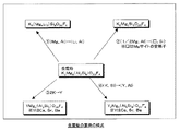
図1に金雲母の置換の様式を示した。金雲母ではKのサイトはNa、Ca、Sr、Baで、また、MgのサイトはLiで、また、Si、AlのサイトはそれぞれAl、Siで置換可能である。置換の様式は図1に示した4種類あり、それぞれの置換の割合により多様な組成の化合物が形成される。
【0018】
これらの結晶構造は例えば、X線回折により容易に同定することが可能である。例えば、KAl2(AlSi3)O10(OH)のX線回折データはJCPDSカードNo.7−25、KMg3(AlSi3)O10F2のX線回折データはJCPDSカードNo.34−0158、BaMg3(Al2Si2)O10F2のX線回折データはJCPDSカードNo.19−117に記載されている。
【0019】
なお、本発明の蛍光体は、紫外線、真空紫外線、電子線、X線等による励起により350〜400nm付近に発光ピークを有する紫外線発光を呈する。
【0020】
また、本発明の発光素子は、電子線、紫外線、希ガス中の放電で得られる真空紫外線により励起して発光できる発光源として、上記の蛍光体を備えることを特徴とする発光素子である。なお、本発明の発光素子としては、例えば、ブラックライト、蛍光ランプ、希ガスランプやプラズマディスプレイパネル(PDP)を構成する放電セル等を例示することができる。特に励起源として紫外線を利用するブラックライト、蛍光ランプ(低圧水銀ランプ)、高圧水銀ランプや、真空紫外線を利用する希ガスランプやPDP用発光素子として有用である。
【0021】
また、本発明の蛍光体を第1の蛍光体とし、該第1の蛍光体と共に、該第1の蛍光体の輻射線を可視光に変換する少なくとも1種の第2の蛍光体を含む蛍光体層を有する発光素子とすることも有用である。特に、第2の蛍光体として青色発光蛍光体を含む蛍光体層を形成した発光素子とすることで、青色発光強度を増大させた発光素子、例えばPDP用発光素子を得ることができる。
【0022】
本発明の蛍光体中の雲母構造を有するアルカリ金属またはアルカリ土類金属フルオロ珪酸塩は下記組成式で表されるものであることが好ましい。
【0023】
(Xa,Yb,Euc)(Mgd,Lie)(Si8−f,Alf)O20F4
(式中、XはNa,Kから選ばれた少なくとも1種類以上の元素、YはCa,Sr,Baから選ばれた少なくとも1種類以上の元素からなり、a、b、c、d、e及びfはそれぞれ、0≦a<2、0≦b<2、0<c≦0.5、1≦a+2b+2c≦4、4≦d≦6、0≦e≦2、5≦d+e≦6、0≦f≦4の範囲の数であり、(a+2b+2c+2d+e−f)=12を満たす。)
本発明の蛍光体中のアルカリ金属またはアルカリ土類金属フルオロ珪酸塩のXイオン量aは0≦a<2であり、またYイオン量bは0≦b<2である。この範囲内では、主に雲母構造を有する化合物が生成し、紫外線、真空紫外線、電子線、X線等による励起で350から400nmにピークを有する紫外線発光を呈する。
【0024】
本発明の蛍光体中のアルカリ金属またはアルカリ土類金属フルオロ珪酸塩のEu量cは0<c≦0.5である。Eu量cが0.5を超えると濃度消光のため、発光効率が低下し、好ましくない。
【0025】
さらに、本発明の蛍光体中のアルカリ金属またはアルカリ土類金属フルオロ珪酸塩のa量、b量及びc量の和は1≦a+2b+2c≦4である。この範囲内では、主に雲母構造を有する化合物が生成し、紫外線、真空紫外線、電子線、X線等による励起で350から400nm付近に発光ピークを有する紫外線発光を呈する。
【0026】
本発明の蛍光体中のアルカリ金属またはアルカリ土類金属フルオロ珪酸塩のMg量dは4≦d≦6であり、またLi量eは0≦e≦2である。この範囲内では、主に雲母構造を有する化合物が生成し、紫外線、真空紫外線、電子線、X線等による励起で350から400nmにピークを有する紫外線発光を呈する。
【0027】
さらに、本発明の蛍光体中のアルカリ金属またはアルカリ土類金属フルオロ珪酸塩のd量とe量の和は5≦d+e≦6である。この範囲内では、主に雲母構造を有する化合物が生成し、紫外線、真空紫外線、電子線、X線等による励起で350から400nmにピークを有する紫外線発光を呈する。
【0028】
本発明の蛍光体中のアルカリ金属またはアルカリ土類金属フルオロ珪酸塩のAl量fは0≦f≦4である。この範囲内では、主に雲母構造を有する化合物が生成し、紫外線、真空紫外線、電子線、X線等による励起で350から400nmにピークを有する紫外線発光を呈する。
【0029】
なお、本発明の蛍光体中のアルカリ金属またはアルカリ土類金属フルオロ珪酸塩のa量、b量、c量、d量、e量及びf量の和は(a+2b+2c+2d+e−f)=12の関係を満たす。この関係を満たすことが上記組成物の電気的中性を保つ上で必要である。
【0030】
さらには、本発明の蛍光体中のアルカリ金属またはアルカリ土類金属フルオロ珪酸塩のa,b及びcが0≦a/(a+b+c)≦0.2であり、かつYが主にSrからなることが好ましい。この範囲で発光効率が良好である。なお、Yが主にSrである場合とは、Yを構成する元素全体に対するSrの割合が50atm%以上である場合を意味する。
【0031】
また、本発明の蛍光体中のアルカリ金属またはアルカリ土類金属フルオロ珪酸塩のa,b及びcが0≦a/(a+b+c)≦0.2であり、かつYが主にBaからなることが好ましい。この範囲で発光効率が良好である。なお、Yが主にBaである場合とは、Yを構成する元素全体に対するBaの割合が50atm%以上である場合を意味する。
【0032】
上記のYイオンであるSr、Baの違いにより発光波長が異なり、Baの場合の方がより短波長の発光を呈する。
【0033】
次に本発明の蛍光体の製造方法の一例を示す。
【0034】
本発明の蛍光体の原料は酸化物、炭酸塩、硝酸塩、硫酸塩、ハロゲン化物、水酸化物など焼成処理中に容易に酸化物またはハロゲン化物になるものを使用することができる。
【0035】
カルシウム原料としては、例えば、酸化カルシウム、水酸化カルシウム、炭酸カルシウム、塩化カルシウム、フッ化カルシウム、硝酸カルシウム、硫酸カルシウム、酢酸カルシウム、蓚酸カルシウム、カルシウムのアルコキシドを使用することができる。
【0036】
ストロンチウム原料としては、例えば、酸化ストロンチウム、水酸化ストロンチウム、炭酸ストロンチウム、塩化ストロンチウム、フッ化ストロンチウム、硝酸ストロンチウム、硫酸ストロンチウム、酢酸ストロンチウム、蓚酸ストロンチウム、ストロンチウムのアルコキシドを使用することができる。
【0037】
バリウム原料としては、例えば、酸化バリウム、炭酸バリウム、塩化バリウム、フッ化バリウム、硝酸バリウム、硫酸バリウム、酢酸バリウム、蓚酸バリウム、バリウムのアルコキシドを使用することができる。
【0038】
ナトリウム原料としては、例えば、炭酸ナトリウム、炭酸水素ナトリウム、硝酸ナトリウム、ナトリウムのアルコキシドを使用することができる。
【0039】
カリウム原料としては、例えば、炭酸カリウム、硝酸カリウム、硫酸カリウム、カリウムのアルコキシドを使用することができる。
【0040】
リチウム原料としては、例えば、炭酸リチウム、硝酸リチウム、酸化リチウム、塩化リチウム、フッ化リチウム、リチウムのアルコキシドを使用することができる。
【0041】
シリコン原料としては、例えば、石英、クリストバライト等の二酸化珪素、シリカゲル、シリコンのアルコキシドを使用することができる。
【0042】
アルミニウム原料としては、例えば、α―アルミナ、γ―アルミナ、水酸化アルミニウム、硝酸アルミニウム、フッ化アルミニウム、アルミニウムのアルコキシドを使用することができる。
【0043】
ユーロピウム原料としては、例えば、酸化ユーロピウム、塩化ユーロピウム、フッ化ユーロピウムを使用することができる。
【0044】
特にフッ素の原料として、フッ化カルシウム、フッ化マグネシウム、フッ化ナトリウム、フッ化カリウム、フッ化ユーロピウム、フッ化アルミニウム等の蛍光体を構成する元素のフッ化物やフッ化アンモニウム等のハロゲンアンモニウム塩を使用することが好ましい。
【0045】
これらの原料を所定量秤量し、混合する。混合方法は公知の方法を使用することができ、湿式混合、乾式混合のどちらでもよい。また、ゾルゲル法、共沈法などの化学反応を利用して原料を調製することもできる。
【0046】
なお、結晶成長を促進させ、発光輝度を向上させるために、化学量論組成より過剰量のハロゲン原料を添加することや、蛍光体原料に対して0.1から10重量%のアルカリ金属のハロゲン化物、硼素化合物等の比較的低融点の化合物を融剤として添加、混合しても良い。
【0047】
この原料混合物を乾燥後、アルミナるつぼ等の耐熱容器に入れて、不活性ガス中、水素ガスなどの還元雰囲気中、または、水蒸気を含む還元雰囲気中、900〜1300℃で1乃至50時間焼成することで本発明の蛍光体を得ることができる。特に、0.1乃至5%の水素を含有する不活性ガスを用いると、付活剤であるEuが2価の状態に良好に保持され、発光強度の強い蛍光体が得られるため好ましい。得られた蛍光体を粉砕し、再焼成を繰り返すことも、均質な蛍光体粉末を得るために有効である。
【0048】
次に、この蛍光体を目的の純度、粒度に調整するために必要に応じ、粉砕、水洗、乾燥、篩い分けを行い、使用する。
【0049】
以上のようにして本発明蛍光体は製造できるが、本発明は、従来より評価されていた254nm、365nmといった波長の紫外線を励起光源とした蛍光体にも使用可能であるが、特に、146nm、173nmといった波長の真空紫外線を励起光源とした蛍光体として有用である。このような短波長域において十分な蛍光量を有し実用上極めて有用である。
【0050】
また、本発明の蛍光体は単独での使用の他に赤、青、緑色発光を呈する蛍光体と混合して使用することができる。本発明の蛍光体の発する紫外線により他の蛍光体を励起し、可視光を得る。本発明の蛍光体と混合する他の蛍光体としてはBaMgAl10O17:Eu、CaMgSi2O6:Eu、(Sr,Ca)10(PO4)6Cl2:Eu、(Ca、Mg)6P4O16:Eu、(Ca,Sr)B2Si2O8:Eu、BaAl2Si2O8:Eu、BaMgAl10O17:Eu,Mn、SrAl2O4:Eu、Sr4Al14O25:Eu、Sr2Al6O11:Euからなる群から選ばれた1種又は2種以上の蛍光体を用いることができる。
【0051】
なお、本発明の蛍光体を構成する雲母構造を有する化合物は層状化合物であり、その形状は薄片状で結晶性の高いものであり、光の放射、反射等において効果的である利点もある。また、雲母構造を有する化合物、特にフッ素系の化合物は熱安定性に優れており、そのため、本発明の蛍光体も熱安定性が優れている。
【0052】
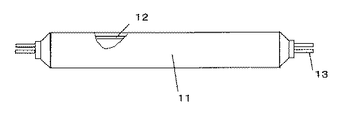
また、本発明の蛍光体は、紫外線励起により発光を得る発光素子、例えば、ブラックライト等を構成することができる。また、赤、青、緑色蛍光体と混合して使用することで蛍光ランプ(低圧水銀ランプ)、高圧水銀ランプを構成することができる。本発明の蛍光体からなる蛍光体膜を備えたブラックライトの一例を図2に示す。ブラックライトは図2に示すように、濃青色フィルターを具備するガラス管11の内面に被覆された蛍光体膜12を備え、更にガラス管11内に所定の放電用ガスを封入してなり、ガラス管11の両端部に取り付けられた電極13に所定電圧を印加し、放電により励起されたガスから発生する紫外線によって蛍光体膜12が発光するものである。本蛍光体は蛍光体膜12を形成する。
【0053】
また、希ガス中の放電で得られる真空紫外線により励起して発光できる発光素子、例えば、PDP(プラズマディスプレイパネル)用の発光素子を構成することができる。
【0054】
本発明の蛍光体からなる蛍光体膜を備えたPDPの一例を図3に示す。
【0055】
2枚のガラス基板21上にそれぞれ縦、横のマトリックス上に電極が構成される。一方は表示データを書き込むデータ電極22で、もう一方は発光のための放電を行う表示電極23である。これら2本を一組として形成される。
【0056】
データ電極は隣接した放電セル間の放電を隔離するためにストライプ状の隔壁24で仕切られる。データ電極上と隔壁面を覆うように赤(R)、緑(G)、青(B)の蛍光体膜25が形成されており、R、G、Bの3セルで1画素が構成される。本発明の蛍光体は青色蛍光体と混合して使用される。この2枚のガラス基板を貼り合わせ、Ne、Xeの混合ガスを封入する。データ電極と表示電極の交点が1セルとなる。表示電極間に百数十ボルトの電圧をかけることで放電を開始させ、放電により励起されたXe原子から真空紫外線を発生させる。各セルには真空紫外線により発光する蛍光体が塗布されており、各々の色の蛍光体は可視光を発生させ、パネル全体の発光にいたる。
【0057】
また、PDPと同様な構成パネルで各放電セルに本発明の蛍光体膜を塗布し、希ガスの放電による真空紫外線を本発明の蛍光体により紫外線に変換し、その紫外線を前面のガラス基板に配置された有機物、無機物からなる光変換材料により赤(R),緑(G),青(B)に変換する形式のディスプレイを構成することができる。
【0058】
【実施例】
以下、実施例により本発明を具体的に説明するが、本発明はこれら実施例のみに限定されるものではない。
【0059】
(1)結晶構造
粉末の結晶構造は粉末X線回折装置(マック・サイエンス社製、商品名MPX3)により同定した。X線源としてはCu−Kα線を使用した。
【0060】
(2)発光評価
・紫外線蛍光評価
市販の分光蛍光光度計(日本分光製、商品名FP−777)を用い、254nmの紫外線による発光スペクトルを測定した。また、励起波長が220から400nmでの励起スペクトルを測定した。
・真空紫外線蛍光評価
光源として、146nm、172nmのエキシマランプ(ウシオ電機製)を使用し、真空チャンバー内にサンプルをセットし、真空度0.1torrにて、発光スペクトルを測定した。
【0061】
(3)混合蛍光体の発光評価
後述の実施例7の蛍光体と青色発光を呈する蛍光体を任意の割合で混合し、混合蛍光体を得る。得られた混合蛍光体の発光強度を146nm、172nmのエキシマランプ(ウシオ電機製)を使用し、真空チャンバー内にサンプルをセットし、真空度0.1torrにて、発光スペクトルを測定した。
【0062】
青色蛍光体としては、BaMgAl10O17:Eu、CaMgSi2O6:Eu、(Sr,Ca)10(PO4)6Cl2:Euを使用した。この青色蛍光体は後述の比較例1から3によって作製したものである。
【0063】
(実施例1)
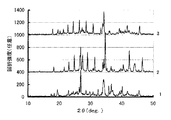
K2CO3 1.60g、MgF2 4.43g、Al2O3 1.21g、SiO2 4.27g、Eu2O3 0.042gの各原料を秤量し、混合した。この混合物を白金製容器に入れ、電気炉に導入し、5vol%の水素ガスを含有した窒素ガスの雰囲気中で1200℃で2時間焼成し、蛍光体を得た。原料混合物の組成から計算したこの蛍光体の組成はK1.96Eu0.02Mg6Al2Si6O20F4である。得られた蛍光体の粉末X線回折結果を図4(図4中、1と付した下段のプロファイル)に示す。得られた蛍光体は金雲母特有の回折パターンを示した。また、他の結晶相の存在は認められなかった。
【0064】
(実施例2)
K2CO3 1.63g、Li2CO3 0.91g、MgF2 3.07g、SiO2 5.91g、Eu2O3 0.087gの各原料を秤量し、混合した。この混合物を白金製容器に入れ、電気炉に導入し、5vol%の水素ガスを含有した窒素ガスの雰囲気中で1000℃で4時間焼成し、蛍光体を得た。原料混合物の組成から計算したこの蛍光体の組成はK1.92Eu0.04Mg4Li2Si8O20F4である。得られた蛍光体は粉末X線回折の結果、金雲母特有の回折パターンを示した。また、他の結晶相の存在は認められなかった。
【0065】
(実施例3)
K2CO3 1.61g、MgF2 3.78g、SiO2 5.84g、Eu2O3 0.086gの各原料を秤量し、混合した。この混合物を白金製容器に入れ、電気炉に導入し、5vol%の水素ガスを含有した窒素ガスの雰囲気中で1100℃で2時間焼成し、蛍光体を得た。原料混合物の組成から計算したこの蛍光体の組成はK1.92Eu0.04Mg5Si8O20F4である。得られた蛍光体は粉末X線回折の結果、金雲母特有の回折パターンを示した。また、他の結晶相の存在は認められなかった。
【0066】
(実施例4)
SrCO3 1.55g、MgF2 4.36g、Al2O3 1.19g、SiO2 4.20g、Eu2O3 0.21gの各原料を秤量し、混合した。この混合物を白金製容器に入れ、電気炉に導入し、1vol%の水素ガスを含有した窒素ガスの雰囲気中で1100℃で2時間焼成し、蛍光体を得た。原料混合物の組成から計算したこの蛍光体の組成はSr0.9Eu0.1Mg6Al2Si6O20F4である。得られた蛍光体は粉末X線回折の結果、金雲母特有の回折パターンを示した。また、他の結晶相の存在は認められなかった。
【0067】
(実施例5)
BaCO3 2.08g、MgF2 4.14g、Al2O3 1.13g、SiO2 3.99g、Eu2O3 0.097gの各原料を秤量し、混合した。この混合物を白金製容器に入れ、電気炉に導入し、5vol%の水素ガスを含有した窒素ガスの雰囲気中で1200℃で2時間焼成し、蛍光体を得た。原料混合物の組成から計算したこの蛍光体の組成はBa0.95Eu0.05Mg6Al2Si6O20F4である。得られた蛍光体は粉末X線回折の結果、金雲母特有の回折パターンを示した。また、他の結晶相の存在は認められなかった。
【0068】
(実施例6)
SrCO3 3.11g、MgF2 3.98g、Al2O3 2.17g、SiO2 2.56g、Eu2O3 0.038gの各原料を秤量し、混合した。この混合物を白金製容器に入れ、電気炉に導入し、4vol%の水素ガスを含有した窒素ガスの雰囲気中で1100℃で2時間焼成し、蛍光体を得た。原料混合物の組成から計算したこの蛍光体の組成はSr1.98Eu0.02Mg6Al4Si4O20F4である。得られた蛍光体の粉末X線回折結果を図4(図4中、2と付した中段のプロファイル)に示す。得られた蛍光体は金雲母特有の回折パターンを示した。また、他の結晶相の存在は認められなかった。
【0069】
(実施例7)
BaCO3 3.02g、MgF2 3.59g、Al2O3 1.96g、SiO2 2.31g、Eu2O3 0.68gの各原料を秤量し、混合した。この混合物を白金製容器に入れ、電気炉に導入し、4vol%の水素ガスを含有した窒素ガスの雰囲気中で1100℃で2時間焼成し、蛍光体を得た。原料混合物の組成から計算したこの蛍光体の組成はBa1.6Eu0.4Mg6Al4Si4O20F4である。得られた蛍光体の粉末X線回折結果を図4(図4中、3と付した上段のプロファイル)に示す。得られた蛍光体は金雲母特有の回折パターンを示した。また、他の結晶相の存在は認められなかった。
【0070】
発光評価
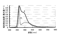
実施例1から7の蛍光体を254nmの紫外線、および146nm、172nmの真空紫外線にて発光評価を行った。図5に実施例1および3の蛍光体の254nmの紫外線励起による発光スペクトルを示す(4は実施例1、5は実施例3の発光スペクトルを示す)。図6に実施例6および7の蛍光体の254nmの紫外線励起による発光スペクトルを示す(6は実施例6、7は実施例7の発光スペクトルを示す)。
【0071】
表1にそれぞれの励起源による蛍光体の発光ピーク波長、発光ピーク強度を示す。なお、表1中の発光ピーク強度は、比較例1の蛍光体の発光ピーク強度を1とした相対値として示してある。実施例2及び3を除くすべての蛍光体で254nmの紫外線、146nm及び172nmの真空紫外線励起により発光を確認した。なお、実施例2及び3の蛍光体は254nmの紫外線励起により発光が認められた。
【0072】
【表1】

実施例7の蛍光体と3種の青色蛍光体とを混合して混合蛍光体を作成し発光評価を行なった。混合蛍光体1は、実施例7の蛍光体と後述の比較例1の組成がBa0.9Eu0.1MgAl10O17の蛍光体とを重量比で10:90となるように混合したもの、混合蛍光体2は、実施例7の蛍光体と後述の比較例2の組成がCa0.98Eu0.02MgSi2O6の蛍光体とを重量比で20:80となるように混合したもの、混合蛍光体3は、実施例7の蛍光体と後述の比較例3の組成がSr9.8Eu0.2P6O24Cl2の蛍光体とを重量比で30:70となるように混合したものである。
【0073】
表2に混合蛍光体1から3について青色蛍光体の種類と混合割合、146nm及び172nmの真空紫外線励起による発光ピーク波長、各々の励起における発光ピーク強度を示す。なお、発光ピーク強度は、各々、混合蛍光体1については比較例1の蛍光体、混合蛍光体2については比較例2の蛍光体、混合蛍光体3については比較例3の蛍光体の発光ピーク強度を1としてえられる相対強度として示している。
【0074】
表2に示すように、混合した3種のすべての青色蛍光体で、実施例7の蛍光体と混合することにより、発光強度が増加することを確認した。
【0075】
【表2】
BaCO3 2.52g、MgCO3 1.20g、Al2O3 6.87g、AlF3 0.60g、Eu2O3 0.25gの各原料を秤量し、混合した。この混合物をアルミナ製容器に入れ、電気炉に導入し、4vol%の水素ガスを含有した窒素ガスの雰囲気中で1500℃で2時間焼成した。この焼成物を粉砕後、同条件でもう一度焼成を行った。この焼成物を粉砕し、組成がBa0.9Eu0.1MgAl10O17の蛍光体を得た。得られた蛍光体の粉末X線回折の結果、β―アルミナ構造を有することが確認された。
【0076】
また、紫外線、真空紫外線励起において450nmに発光ピークを有する青色発光を確認した。
【0077】
(比較例2)CaMgSi2O6:Euの作製
SiO2 5.49g、CaCO3 4.48g、MgCO3 3.85g、Eu2O3 0.32g、NH4Cl 0.50gの蛍光体原料とフラックスの塩化アンモニウムを秤量し、混合した。この混合物をH2=4%ガス(N2バランス)中、1150℃で2時間焼成し、組成がCa0.98Eu0.02MgSi2O6の蛍光体を得た。
【0078】
得られた蛍光体のX線回折の結果、CaMgSi2O6がほぼ単相で得られていることを確認した。また、紫外線、真空紫外線励起において448nmに発光ピークを有する青色発光を確認した。
【0079】
(比較例3)Sr10(PO4)6Cl2:Euの作製
SrHPO4 7.20g、SrCO3 1.73g、SrCl2 2.07g、Eu2O3 0.23gの各原料を秤量し、混合した。この混合物をH2=4%ガス(N2バランス)中、1100℃で2時間焼成し、組成がSr9.8Eu0.2P6O24Cl2の蛍光体を得た。
【0080】
得られた蛍光体のX線回折の結果、Sr10(PO4)6Cl2がほぼ単相で得られていることを確認した。また、紫外線、真空紫外線励起において448nmに発光ピークを有する青色発光を確認した。
【0081】
【発明の効果】
本発明によれば、化学的安定性が高く、特に真空紫外線励起において強い発光を呈する新規な蛍光体を提供できる。また、該蛍光体を用いて、蛍光体を励起して発光させる発光素子を構成することにより、高強度の紫外線発光または、青色発光を呈する発光素子を提供することができる。
【図面の簡単な説明】
【図1】本発明の蛍光体を構成するアルカリ金属またはアルカリ土類金属フルオロ珪酸塩の元素置換の様式を示す図である。
【図2】本発明の蛍光体を含有する蛍光体膜を備えた蛍光ランプの一例を示す図である。
【図3】本発明の蛍光体を含有する蛍光体膜を備えたPDPの一例を示す図である。
【図4】実施例1、6、7で得られた蛍光体粉末のX線回折パターンを示す図である(1:実施例1、2:実施例6、3:実施例7)。
【図5】実施例1および3で得られた蛍光体粉末の波長=254nmの紫外線励起による発光スペクトルを示す図である(4:実施例1、5:実施例3)。
【図6】実施例6および7で得られた蛍光体粉末の波長=254nmの紫外線励起による発光スペクトルを示す図である(6:実施例6、7:実施例7)。
【図7】実施例6および7で得られた蛍光体粉末の励起スペクトルを示す図である(8:実施例6、9:実施例7)。
【符号の説明】
11 ガラス管
12 蛍光体膜
13 電極
21 ガラス基板
22 データ電極
23 表示電極
24 隔壁
25 蛍光体膜[0001]
TECHNICAL FIELD OF THE INVENTION
The present invention relates to a europium-activated fluorosilicate phosphor that emits high-intensity ultraviolet light when excited by ultraviolet light, vacuum ultraviolet light, electron beam, or X-ray, particularly ultraviolet light or vacuum ultraviolet light, and a light emitting device using the same.
[0002]
[Prior art]
BACKGROUND ART Conventionally, phosphors have been widely used for displays such as fluorescent lamps, CRTs, and PDPs, radiographic intensifying screens, and indoor / outdoor decorations. These phosphors emit near-ultraviolet light to visible light by ultraviolet rays, vacuum ultraviolet rays, electron beams, and X-rays as excitation sources. The structure of these phosphors is such that a small amount of luminescent ions such as Eu and Mn are added to a base material crystal such as a metal oxide, sulfide, oxysulfide or halide. In general, phosphors are required to have various characteristics such as compatibility with excitation wavelength and stability, in addition to emission color and emission intensity.
[0003]
Conventionally, ultraviolet light emitting phosphors have been used as fluorescent lamps for black lights, copiers, insects, and health lines, and in recent years, have also been used as light sources for photocatalysts (for example, see Non-Patent Document 1). ).
[0004]
In recent years, light-emitting elements having a mechanism for causing a phosphor to emit light by vacuum ultraviolet excitation, such as a plasma display panel (PDP) and a rare gas lamp, have been actively developed. Among them, PDP is expected as a large-screen flat display, which is difficult in a cathode ray tube (CRT) and a color liquid crystal display.
[0005]
A PDP is a display element configured by arranging a large number of minute discharge cells in a matrix. A rare gas such as He-Xe, Ne-Xe, or Ar is sealed in the space in each discharge cell, and the phosphor obtained is excited by vacuum ultraviolet light having a wavelength of 147 nm or 173 nm obtained by discharging the rare gas. Emit visible light. Blue, green, and red phosphors, which are three primary colors of light, are applied to each discharge cell to perform full-color display.
[0006]
The rare gas lamp is a lamp having a mechanism that excites a phosphor with vacuum ultraviolet rays obtained by discharge of a rare gas and emits visible light. There is a concern that mercury affects the environment in fluorescent lamps that have been used conventionally. Since noble gas lamps do not use mercury, they are receiving attention from the viewpoint of environmental problems.
[0007]
Phosphors for excitation of vacuum ultraviolet rays, particularly for PDPs, have been searched mainly for phosphors for CRTs and fluorescent lamps, and three primary colors have already been proposed. As a blue phosphor, for example, BaMgAl10O17: Eu, green phosphor such as Zn2SiO4: Mn, BaAl12O19: Mn, for example, (Y, Gd) BO as a red phosphor3: Eu is currently used. Among them, the blue phosphor BaMgAl10O17: Eu is significantly deteriorated by heat treatment during panel production and aging due to vacuum ultraviolet rays more remarkably than other color phosphors, and a new vacuum ultraviolet excitation phosphor excellent in life characteristics is desired.
[0008]
To solve the above problems, a new phosphor has been developed, but the initial luminance is insufficient and BaMgAl10O17: No material to replace Eu has been found.
[0009]
On the other hand, BaMgAl10O17: A method of mixing and using a phosphor that emits light in the ultraviolet region and a blue phosphor for the purpose of reducing Eu degradation and increasing the luminance has been disclosed (for example, see Patent Document 1). In this case, the vacuum ultraviolet light is converted into ultraviolet light by the ultraviolet light emitting phosphor, and the ultraviolet light is absorbed and emitted by the blue phosphor. However, there is no phosphor that emits sufficient ultraviolet light when excited by vacuum ultraviolet light, and has not been put to practical use.
[0010]
[Patent Document 1]
JP-A-2002-80843 (page 1-2)
[Non-patent document 1]
"Phosphor Handbook", edited by Phosphors Society of Japan, Ohmsha, published December 25, 1987, pages 208-209.
[0011]
[Problems to be solved by the invention]
The present invention provides a novel chemically stable phosphor which efficiently emits ultraviolet light under various excitations, particularly ultraviolet and vacuum ultraviolet excitations, and a light emitting device using the same.
[0012]
[Means for Solving the Problems]
The present inventors have conducted intensive studies in order to solve the above problems, and as a result, it has been found that a compound activated with divalent europium having a unique crystal structure emits ultraviolet light and is a chemically stable phosphor. And completed the present invention.
[0013]
Hereinafter, the present invention will be described in detail.
[0014]
The phosphor of the present invention has an alkali metal or alkaline earth metal fluorosilicate having a mica crystal structure (hereinafter referred to as “mica structure”) activated with divalent europium as a base. That is, the phosphor of the present invention is a phosphor composed of an alkali metal or alkaline earth metal fluorosilicate having a mica structure, activated with divalent europium, and is an alkali metal or alkaline earth metal fluorosilicate. May be a substance obtained by activating divalent europium itself, or a substance having, as a main component, a substance obtained by activating divalent europium on an alkali metal or alkaline earth metal fluorosilicate having a mica structure And SiO2And other components may be included. Specifically, the alkali metal or alkaline earth metal fluorosilicate having a mica structure activated with divalent europium is preferably 80% by weight or more, more preferably 90% by weight or more.
[0015]
Mica is known as a naturally occurring mineral and is generally a compound having a monoclinic crystal structure. The general formula is X2Y4 ~ 6Z8O20(OH, F)4Is represented by In this equation, X = Na, K, Ca, Sr, Ba, Y = Mg, Fe, Al, Ti, Mn, Cr, Li, and Z = Si, Al.
[0016]
Mica can be broadly classified into muscovite having 4 (or between 4 and 5) Y ions and phlogopite having 6 (or between 5 and 6) Y ions. Muscovite has a monoclinic crystal structure and has the general formula KAl2(AlSi3) O10(OH)2Is represented by Phlogopite has a monoclinic crystal structure and has the general formula KMg3(AlSi3) O10(OH)2Is represented by The alkali metal or alkaline earth metal fluorosilicate having a mica structure in the phosphor of the present invention may have a muscovite crystal structure, or may have a phlogopite crystal structure. good.
[0017]
FIG. 1 shows the mode of substitution of phlogopite. In phlogopite, the K site can be replaced with Na, Ca, Sr, and Ba, the Mg site can be replaced with Li, and the Si and Al sites can be replaced with Al and Si, respectively. There are four types of substitution shown in FIG. 1, and compounds having various compositions are formed depending on the ratio of each substitution.
[0018]
These crystal structures can be easily identified by, for example, X-ray diffraction. For example, KAl2(AlSi3) O10X-ray diffraction data of (OH) was obtained from JCPDS card No. 7-25, KMg3(AlSi3) O10F2X-ray diffraction data of JCPDS Card No. 34-0158, BaMg3(Al2Si2) O10F2X-ray diffraction data of JCPDS Card No. 19-117.
[0019]
The phosphor of the present invention emits ultraviolet light having an emission peak near 350 to 400 nm when excited by ultraviolet light, vacuum ultraviolet light, electron beam, X-ray, or the like.
[0020]
Further, a light-emitting element of the present invention is a light-emitting element comprising the above-described phosphor as a light-emitting source capable of emitting light by being excited by an electron beam, ultraviolet light, or vacuum ultraviolet light obtained by discharge in a rare gas. In addition, as the light emitting element of the present invention, for example, a black light, a fluorescent lamp, a rare gas lamp, a discharge cell constituting a plasma display panel (PDP) and the like can be exemplified. Particularly, it is useful as a black light, a fluorescent lamp (low-pressure mercury lamp), a high-pressure mercury lamp, a rare gas lamp using vacuum ultraviolet light, or a light emitting element for PDP using ultraviolet light as an excitation source.
[0021]
In addition, the phosphor of the present invention is a first phosphor, and the first phosphor and at least one kind of second phosphor that converts radiation of the first phosphor into visible light. It is also useful to form a light emitting element having a body layer. In particular, by using a light emitting element in which a phosphor layer containing a blue light emitting phosphor is formed as the second phosphor, a light emitting element with increased blue light emission intensity, for example, a light emitting element for a PDP can be obtained.
[0022]
The alkali metal or alkaline earth metal fluorosilicate having a mica structure in the phosphor of the present invention is preferably represented by the following composition formula.
[0023]
(Xa, Yb, Euc) (Mgd, Lie) (Si8-f, Alf) O20F4
(Where X is at least one or more elements selected from Na and K, Y is at least one or more elements selected from Ca, Sr and Ba, and a, b, c, d, e and f is 0 ≦ a <2, 0 ≦ b <2, 0 <c ≦ 0.5, 1 ≦ a + 2b + 2c ≦ 4, 4 ≦ d ≦ 6, 0 ≦ e ≦ 2, 5 ≦ d + e ≦ 6, 0 ≦ It is a number in the range of f ≦ 4, and satisfies (a + 2b + 2c + 2d + ef) = 12.)
The amount of X ions a of the alkali metal or alkaline earth metal fluorosilicate in the phosphor of the present invention is 0 ≦ a <2, and the amount of Y ions b is 0 ≦ b <2. Within this range, a compound mainly having a mica structure is generated, and emits ultraviolet light having a peak at 350 to 400 nm when excited by ultraviolet light, vacuum ultraviolet light, electron beam, X-ray, or the like.
[0024]
The Eu content c of the alkali metal or alkaline earth metal fluorosilicate in the phosphor of the present invention is 0 <c ≦ 0.5. If the Eu amount c exceeds 0.5, the luminescence efficiency decreases because of concentration quenching, which is not preferable.
[0025]
Further, the sum of the amounts a, b and c of the alkali metal or alkaline earth metal fluorosilicate in the phosphor of the present invention is 1 ≦ a + 2b + 2c ≦ 4. Within this range, a compound mainly having a mica structure is generated, and emits ultraviolet light having an emission peak near 350 to 400 nm when excited by ultraviolet light, vacuum ultraviolet light, electron beam, X-ray, or the like.
[0026]
The Mg amount d of the alkali metal or alkaline earth metal fluorosilicate in the phosphor of the present invention is 4 ≦ d ≦ 6, and the Li amount e is 0 ≦ e ≦ 2. Within this range, a compound mainly having a mica structure is generated, and emits ultraviolet light having a peak at 350 to 400 nm when excited by ultraviolet light, vacuum ultraviolet light, electron beam, X-ray, or the like.
[0027]
Further, the sum of the amounts d and e of the alkali metal or alkaline earth metal fluorosilicate in the phosphor of the present invention is 5 ≦ d + e ≦ 6. Within this range, a compound mainly having a mica structure is generated, and emits ultraviolet light having a peak at 350 to 400 nm when excited by ultraviolet light, vacuum ultraviolet light, electron beam, X-ray, or the like.
[0028]
The Al content f of the alkali metal or alkaline earth metal fluorosilicate in the phosphor of the present invention is 0 ≦ f ≦ 4. Within this range, a compound mainly having a mica structure is generated, and emits ultraviolet light having a peak at 350 to 400 nm when excited by ultraviolet light, vacuum ultraviolet light, electron beam, X-ray, or the like.
[0029]
It should be noted that the sum of the amounts a, b, c, d, e and f of the alkali metal or alkaline earth metal fluorosilicate in the phosphor of the present invention has a relationship of (a + 2b + 2c + 2d + ef) = 12. Fulfill. It is necessary to satisfy this relationship in order to maintain the electrical neutrality of the composition.
[0030]
Further, a, b and c of the alkali metal or alkaline earth metal fluorosilicate in the phosphor of the present invention satisfy 0 ≦ a / (a + b + c) ≦ 0.2 and Y mainly consists of Sr. Is preferred. Luminous efficiency is good in this range. The case where Y is mainly Sr means that the ratio of Sr to all the elements constituting Y is 50 atm% or more.
[0031]
In addition, a, b and c of the alkali metal or alkaline earth metal fluorosilicate in the phosphor of the present invention are such that 0 ≦ a / (a + b + c) ≦ 0.2 and Y mainly consists of Ba. preferable. Luminous efficiency is good in this range. The case where Y is mainly Ba means that the ratio of Ba to all the elements constituting Y is 50 atm% or more.
[0032]
The emission wavelength differs depending on the difference between the Y ions Sr and Ba, and the emission of shorter wavelength is exhibited in the case of Ba.
[0033]
Next, an example of the method for producing the phosphor of the present invention will be described.
[0034]
As the raw material of the phosphor of the present invention, oxides, carbonates, nitrates, sulfates, halides, hydroxides, and the like that can easily become oxides or halides during the firing treatment can be used.
[0035]
As the calcium raw material, for example, calcium oxide, calcium hydroxide, calcium carbonate, calcium chloride, calcium fluoride, calcium nitrate, calcium sulfate, calcium acetate, calcium oxalate, and alkoxide of calcium can be used.
[0036]
Examples of the strontium raw material include strontium oxide, strontium hydroxide, strontium carbonate, strontium chloride, strontium fluoride, strontium nitrate, strontium sulfate, strontium acetate, strontium oxalate, and strontium alkoxide.
[0037]
As the barium raw material, for example, barium oxide, barium carbonate, barium chloride, barium fluoride, barium nitrate, barium sulfate, barium acetate, barium oxalate, and barium alkoxide can be used.
[0038]
As the sodium raw material, for example, sodium carbonate, sodium hydrogencarbonate, sodium nitrate and sodium alkoxide can be used.
[0039]
As the potassium raw material, for example, potassium carbonate, potassium nitrate, potassium sulfate, and alkoxide of potassium can be used.
[0040]
As the lithium raw material, for example, lithium carbonate, lithium nitrate, lithium oxide, lithium chloride, lithium fluoride, and lithium alkoxide can be used.
[0041]
As the silicon raw material, for example, silicon dioxide such as quartz and cristobalite, silica gel, and silicon alkoxide can be used.
[0042]
As the aluminum raw material, for example, α-alumina, γ-alumina, aluminum hydroxide, aluminum nitrate, aluminum fluoride, and aluminum alkoxide can be used.
[0043]
As the europium raw material, for example, europium oxide, europium chloride, and europium fluoride can be used.
[0044]
In particular, as a raw material of fluorine, a fluoride of an element constituting a phosphor such as calcium fluoride, magnesium fluoride, sodium fluoride, potassium fluoride, europium fluoride, or aluminum fluoride, or a halogen ammonium salt such as ammonium fluoride may be used. It is preferred to use.
[0045]
These raw materials are weighed in predetermined amounts and mixed. Known mixing methods can be used, and either wet mixing or dry mixing may be used. In addition, the raw material can be prepared using a chemical reaction such as a sol-gel method or a coprecipitation method.
[0046]
In order to promote crystal growth and improve emission luminance, an excessive amount of a halogen material may be added to the stoichiometric composition, or 0.1 to 10% by weight of an alkali metal halogen may be added to the phosphor material. A compound having a relatively low melting point such as a compound or a boron compound may be added and mixed as a flux.
[0047]
After drying this raw material mixture, it is placed in a heat-resistant container such as an alumina crucible and fired at 900 to 1300 ° C. for 1 to 50 hours in an inert gas, a reducing atmosphere such as a hydrogen gas, or a reducing atmosphere containing steam. Thus, the phosphor of the present invention can be obtained. In particular, when an inert gas containing 0.1 to 5% of hydrogen is used, Eu as an activator is preferably maintained in a divalent state, and a phosphor with high emission intensity is preferably obtained. It is also effective to grind the obtained phosphor and repeat re-firing to obtain a homogeneous phosphor powder.
[0048]
Next, the phosphor is pulverized, washed with water, dried, and sieved as necessary in order to adjust the purity and particle size to a desired value.
[0049]
Although the phosphor of the present invention can be produced as described above, the present invention can also be used for a phosphor using an ultraviolet light having a wavelength of 254 nm or 365 nm, which has been conventionally evaluated, as an excitation light source. It is useful as a phosphor using a vacuum ultraviolet ray having a wavelength of 173 nm as an excitation light source. It has a sufficient amount of fluorescence in such a short wavelength region and is extremely useful in practice.
[0050]
The phosphor of the present invention can be used alone or in combination with a phosphor that emits red, blue, or green light. The other phosphor is excited by ultraviolet rays emitted from the phosphor of the present invention to obtain visible light. Another phosphor mixed with the phosphor of the present invention is BaMgAl.10O17: Eu, CaMgSi2O6: Eu, (Sr, Ca)10(PO4)6Cl2: Eu, (Ca, Mg)6P4O16: Eu, (Ca, Sr) B2Si2O8: Eu, BaAl2Si2O8: Eu, BaMgAl10O17: Eu, Mn, SrAl2O4: Eu, Sr4Al14O25: Eu, Sr2Al6O11: One or more phosphors selected from the group consisting of Eu can be used.
[0051]
The compound having a mica structure that constitutes the phosphor of the present invention is a layered compound, which is flaky and highly crystalline, and has an advantage that it is effective in light emission and reflection. Further, a compound having a mica structure, particularly a fluorine-based compound, has excellent thermal stability, and therefore, the phosphor of the present invention also has excellent thermal stability.
[0052]
Further, the phosphor of the present invention can constitute a light emitting element that emits light by excitation with ultraviolet light, for example, a black light. A fluorescent lamp (low-pressure mercury lamp) and a high-pressure mercury lamp can be formed by mixing and using red, blue, and green phosphors. FIG. 2 shows an example of a black light provided with a phosphor film made of the phosphor of the present invention. As shown in FIG. 2, the black light includes a
[0053]
Further, a light-emitting element which can emit light when excited by vacuum ultraviolet light obtained by discharge in a rare gas, for example, a light-emitting element for a PDP (plasma display panel) can be formed.
[0054]
FIG. 3 shows an example of a PDP provided with a phosphor film made of the phosphor of the present invention.
[0055]
Electrodes are formed on vertical and horizontal matrices on two
[0056]
The data electrodes are separated by stripe-shaped
[0057]
In addition, the phosphor film of the present invention is applied to each discharge cell using the same panel as the PDP, and the vacuum ultraviolet light generated by the discharge of the rare gas is converted into ultraviolet light by the phosphor of the present invention, and the ultraviolet light is applied to the front glass substrate. It is possible to configure a display of a type in which red (R), green (G), and blue (B) are converted by the disposed light conversion material including an organic substance and an inorganic substance.
[0058]
【Example】
Hereinafter, the present invention will be described specifically with reference to Examples, but the present invention is not limited to only these Examples.
[0059]
(1) Crystal structure
The crystal structure of the powder was identified by a powder X-ray diffractometer (trade name: MPX3, manufactured by Mac Science). Cu-Kα radiation was used as an X-ray source.
[0060]
(2) Emission evaluation
・ Ultraviolet fluorescence evaluation
Using a commercially available spectrofluorometer (manufactured by JASCO Corporation, trade name: FP-777), the emission spectrum with 254 nm ultraviolet light was measured. Further, an excitation spectrum at an excitation wavelength of 220 to 400 nm was measured.
・ Vacuum ultraviolet fluorescence evaluation
Using a 146 nm and 172 nm excimer lamp (made by Ushio Inc.) as a light source, the sample was set in a vacuum chamber, and the emission spectrum was measured at a degree of vacuum of 0.1 torr.
[0061]
(3) Emission evaluation of mixed phosphor
A phosphor of Example 7, which will be described later, and a phosphor that emits blue light are mixed at an arbitrary ratio to obtain a mixed phosphor. A sample was set in a vacuum chamber using an excimer lamp (manufactured by Ushio Inc.) with emission intensity of 146 nm and 172 nm of the obtained mixed phosphor, and the emission spectrum was measured at a degree of vacuum of 0.1 torr.
[0062]
As a blue phosphor, BaMgAl10O17: Eu, CaMgSi2O6: Eu, (Sr, Ca)10(PO4)6Cl2: Eu was used. This blue phosphor was produced by Comparative Examples 1 to 3 described later.
[0063]
(Example 1)
K2CO3 1.60 g, MgF2 4.43 g, Al2O3 1.21 g, SiO2 4.27 g, Eu2O3 0.042 g of each raw material was weighed and mixed. This mixture was put in a platinum container, introduced into an electric furnace, and fired at 1200 ° C. for 2 hours in an atmosphere of nitrogen gas containing 5 vol% of hydrogen gas to obtain a phosphor. The composition of this phosphor calculated from the composition of the raw material mixture is K1.96Eu0.02Mg6Al2Si6O20F4It is. The results of powder X-ray diffraction of the obtained phosphor are shown in FIG. 4 (lower profile denoted by 1 in FIG. 4). The obtained phosphor showed a diffraction pattern peculiar to phlogopite. No other crystal phases were found.
[0064]
(Example 2)
K2CO3 1.63 g, Li2CO3 0.91 g, MgF2 3.07 g, SiO2 5.91 g, Eu2O3 0.087 g of each raw material was weighed and mixed. This mixture was put in a platinum container, introduced into an electric furnace, and fired at 1000 ° C. for 4 hours in an atmosphere of nitrogen gas containing 5 vol% of hydrogen gas to obtain a phosphor. The composition of this phosphor calculated from the composition of the raw material mixture is K1.92Eu0.04Mg4Li2Si8O20F4It is. As a result of powder X-ray diffraction, the obtained phosphor showed a diffraction pattern peculiar to phlogopite. No other crystal phases were found.
[0065]
(Example 3)
K2CO3 1.61 g, MgF2 3.78 g, SiO2 5.84 g, Eu2O3 0.086 g of each raw material was weighed and mixed. This mixture was put in a platinum container, introduced into an electric furnace, and fired at 1100 ° C. for 2 hours in an atmosphere of nitrogen gas containing 5 vol% of hydrogen gas to obtain a phosphor. The composition of this phosphor calculated from the composition of the raw material mixture is K1.92Eu0.04Mg5Si8O20F4It is. As a result of powder X-ray diffraction, the obtained phosphor showed a diffraction pattern peculiar to phlogopite. No other crystal phases were found.
[0066]
(Example 4)
SrCO3 1.55 g, MgF2 4.36 g, Al2O3 1.19 g, SiO2 4.20 g, Eu2O3 0.21 g of each raw material was weighed and mixed. This mixture was put into a platinum container, introduced into an electric furnace, and fired at 1100 ° C. for 2 hours in an atmosphere of nitrogen gas containing 1 vol% of hydrogen gas to obtain a phosphor. The composition of this phosphor calculated from the composition of the raw material mixture is Sr0.9Eu0.1Mg6Al2Si6O20F4It is. As a result of powder X-ray diffraction, the obtained phosphor showed a diffraction pattern peculiar to phlogopite. No other crystal phases were found.
[0067]
(Example 5)
BaCO3 2.08g, MgF2 4.14 g, Al2O3 1.13 g, SiO2 3.99 g, Eu2O3 0.097 g of each raw material was weighed and mixed. This mixture was put in a platinum container, introduced into an electric furnace, and fired at 1200 ° C. for 2 hours in an atmosphere of nitrogen gas containing 5 vol% of hydrogen gas to obtain a phosphor. The composition of this phosphor calculated from the composition of the raw material mixture is Ba0.95Eu0.05Mg6Al2Si6O20F4It is. As a result of powder X-ray diffraction, the obtained phosphor showed a diffraction pattern peculiar to phlogopite. No other crystal phases were found.
[0068]
(Example 6)
SrCO3 3.11 g, MgF2 3.98 g, Al2O3 2.17 g, SiO2 2.56 g, Eu2O3 0.038 g of each raw material was weighed and mixed. This mixture was put in a platinum container, introduced into an electric furnace, and fired at 1100 ° C. for 2 hours in an atmosphere of nitrogen gas containing 4 vol% of hydrogen gas to obtain a phosphor. The composition of this phosphor calculated from the composition of the raw material mixture is Sr1.98Eu0.02Mg6Al4Si4O20F4It is. The powder X-ray diffraction result of the obtained phosphor is shown in FIG. 4 (the middle profile denoted by 2 in FIG. 4). The obtained phosphor showed a diffraction pattern peculiar to phlogopite. No other crystal phases were found.
[0069]
(Example 7)
BaCO3 3.02 g, MgF2 3.59 g, Al2O3 1.96 g, SiO2 2.31 g, Eu2O3 0.68 g of each raw material was weighed and mixed. This mixture was put in a platinum container, introduced into an electric furnace, and fired at 1100 ° C. for 2 hours in an atmosphere of nitrogen gas containing 4 vol% of hydrogen gas to obtain a phosphor. The composition of this phosphor calculated from the composition of the raw material mixture is Ba1.6Eu0.4Mg6Al4Si4O20F4It is. The powder X-ray diffraction result of the obtained phosphor is shown in FIG. 4 (the upper profile denoted by 3 in FIG. 4). The obtained phosphor showed a diffraction pattern peculiar to phlogopite. No other crystal phases were found.
[0070]
Luminescence evaluation
The phosphors of Examples 1 to 7 were evaluated for light emission using ultraviolet light of 254 nm and vacuum ultraviolet light of 146 nm and 172 nm. FIG. 5 shows the emission spectra of the phosphors of Examples 1 and 3 when excited by ultraviolet light at 254 nm (4 shows the emission spectra of Examples 1 and 5). FIG. 6 shows the emission spectra of the phosphors of Examples 6 and 7 when excited by ultraviolet light at 254 nm (6 shows the emission spectra of Examples 6 and 7).
[0071]
Table 1 shows the emission peak wavelength and emission peak intensity of the phosphor by each excitation source. The emission peak intensities in Table 1 are shown as relative values with the emission peak intensity of the phosphor of Comparative Example 1 being 1. Light emission was confirmed by excitation of 254 nm ultraviolet light, 146 nm and 172 nm vacuum ultraviolet light for all the phosphors except Examples 2 and 3. The phosphors of Examples 2 and 3 emitted light when excited with ultraviolet light of 254 nm.
[0072]
[Table 1]
The phosphor of Example 7 and three types of blue phosphors were mixed to prepare a mixed phosphor, and the luminescence was evaluated. In the mixed phosphor 1, the composition of the phosphor of Example 7 and the composition of Comparative Example 1 described later were Ba.0.9Eu0.1MgAl10O17The phosphor of Example 7 was mixed with the phosphor of Example 7 and the composition of Comparative Example 2 described later was Ca.0.98Eu0.02MgSi2O6The phosphor of Example 7 was mixed with the phosphor of Example 7 in a weight ratio of 20:80.9.8Eu0.2P6O24Cl2And the phosphors are mixed at a weight ratio of 30:70.
[0073]
Table 2 shows the types and mixing ratios of the blue phosphors for the mixed phosphors 1 to 3, the emission peak wavelengths at 146 nm and 172 nm, and the emission peak intensities at each excitation. The emission peak intensities of the phosphor of Comparative Example 1 for Mixed Phosphor 1, the phosphor of Comparative Example 2 for
[0074]
As shown in Table 2, it was confirmed that the emission intensity was increased by mixing the three types of blue phosphors with the phosphor of Example 7.
[0075]
[Table 2]
BaCO3 2.52g, MgCO3 1.20 g, Al2O3 6.87 g, AlF3 0.60 g, Eu2O3 0.25 g of each raw material was weighed and mixed. This mixture was placed in an alumina container, introduced into an electric furnace, and fired at 1500 ° C. for 2 hours in an atmosphere of nitrogen gas containing 4 vol% of hydrogen gas. After crushing the fired product, firing was performed again under the same conditions. This calcined product is pulverized and the composition is0.9Eu0.1MgAl10O17Was obtained. As a result of powder X-ray diffraction of the obtained phosphor, it was confirmed that the phosphor had a β-alumina structure.
[0076]
In addition, blue light emission having a light emission peak at 450 nm when excited by ultraviolet light or vacuum ultraviolet light was confirmed.
[0077]
(Comparative Example 2) CaMgSi2O6: Preparation of Eu
SiO2 5.49 g, CaCO3 4.48 g, MgCO3 3.85 g, Eu2O3 0.32 g, NH40.50 g of the phosphor raw material and ammonium chloride as a flux were weighed and mixed. This mixture is2= 4% gas (N2In the balance), calcined at 1150 ° C for 2 hours, and the composition was Ca0.98Eu0.02MgSi2O6Was obtained.
[0078]
As a result of X-ray diffraction of the obtained phosphor, CaMgSi2O6Was obtained in almost a single phase. In addition, blue light emission having a light emission peak at 448 nm was confirmed by excitation of ultraviolet light and vacuum ultraviolet light.
[0079]
(Comparative Example 3) Sr10(PO4)6Cl2: Preparation of Eu
SrHPO4 7.20 g, SrCO3 1.73 g, SrCl2 2.07 g, Eu2O3 0.23 g of each raw material was weighed and mixed. This mixture is2= 4% gas (N2In the balance), baking was performed at 1100 ° C. for 2 hours, and the composition was Sr.9.8Eu0.2P6O24Cl2Was obtained.
[0080]
As a result of X-ray diffraction of the obtained phosphor, Sr10(PO4)6Cl2Was obtained in almost a single phase. In addition, blue light emission having a light emission peak at 448 nm was confirmed by excitation of ultraviolet light and vacuum ultraviolet light.
[0081]
【The invention's effect】
ADVANTAGE OF THE INVENTION According to this invention, the chemical stability is high, and the novel fluorescent substance which shows strong light emission especially in vacuum ultraviolet excitation can be provided. In addition, a light-emitting element that emits high-intensity ultraviolet light or blue light can be provided by using the phosphor to form a light-emitting element that excites the phosphor to emit light.
[Brief description of the drawings]
FIG. 1 is a diagram showing a mode of element substitution of an alkali metal or alkaline earth metal fluorosilicate constituting a phosphor of the present invention.
FIG. 2 is a view showing an example of a fluorescent lamp provided with a phosphor film containing the phosphor of the present invention.
FIG. 3 is a view showing an example of a PDP provided with a phosphor film containing the phosphor of the present invention.
FIG. 4 is a diagram showing an X-ray diffraction pattern of the phosphor powder obtained in Examples 1, 6, and 7 (1: Example 1, 2: Example 6, 3: Example 7).
FIG. 5 is a diagram showing emission spectra of the phosphor powders obtained in Examples 1 and 3 when excited by ultraviolet light at a wavelength of 254 nm (4: Examples 1, 5: Example 3).
FIG. 6 is a diagram showing emission spectra of the phosphor powders obtained in Examples 6 and 7 when excited by ultraviolet light at a wavelength of 254 nm (6: Examples 6 and 7: Example 7).
FIG. 7 is a diagram showing excitation spectra of the phosphor powders obtained in Examples 6 and 7 (8: Examples 6, 9: Example 7).
[Explanation of symbols]
11 Glass tube
12. Phosphor film
13 electrodes
21 Glass substrate
22 Data electrode
23 Display electrode
24 partition
25 phosphor film
Claims (10)
(Xa,Yb,Euc)(Mgd,Lie)(Si8−f,Alf)O20F4
(式中、XはNa,Kから選ばれた少なくとも1種類以上の元素、YはCa,Sr,Baから選ばれた少なくとも1種類以上の元素からなり、a、b、c、d、e及びfはそれぞれ、0≦a<2、0≦b<2、0<c≦0.5、1≦a+2b+2c≦4、4≦d≦6、0≦e≦2、5≦d+e≦6、0≦f≦4の範囲の数であり、(a+2b+2c+2d+e−f)=12を満たす。)The phosphor according to claim 1, wherein the alkali metal or alkaline earth metal fluorosilicate having a mica structure is represented by the following composition formula.
(X a, Y b, Eu c) (Mg d, Li e) (Si 8-f, Al f) O 20 F 4
(Where X is at least one or more elements selected from Na and K, Y is at least one or more elements selected from Ca, Sr and Ba, and a, b, c, d, e and f is 0 ≦ a <2, 0 ≦ b <2, 0 <c ≦ 0.5, 1 ≦ a + 2b + 2c ≦ 4, 4 ≦ d ≦ 6, 0 ≦ e ≦ 2, 5 ≦ d + e ≦ 6, 0 ≦ It is a number in the range of f ≦ 4, and satisfies (a + 2b + 2c + 2d + ef) = 12.)
Priority Applications (1)
| Application Number | Priority Date | Filing Date | Title |
|---|---|---|---|
| JP2003021796A JP2004231786A (en) | 2003-01-30 | 2003-01-30 | Phosphor and light-emitting device |
Applications Claiming Priority (1)
| Application Number | Priority Date | Filing Date | Title |
|---|---|---|---|
| JP2003021796A JP2004231786A (en) | 2003-01-30 | 2003-01-30 | Phosphor and light-emitting device |
Publications (1)
| Publication Number | Publication Date |
|---|---|
| JP2004231786A true JP2004231786A (en) | 2004-08-19 |
Family
ID=32951037
Family Applications (1)
| Application Number | Title | Priority Date | Filing Date |
|---|---|---|---|
| JP2003021796A Pending JP2004231786A (en) | 2003-01-30 | 2003-01-30 | Phosphor and light-emitting device |
Country Status (1)
| Country | Link |
|---|---|
| JP (1) | JP2004231786A (en) |
Cited By (6)
| Publication number | Priority date | Publication date | Assignee | Title |
|---|---|---|---|---|
| WO2007109978A1 (en) * | 2006-03-24 | 2007-10-04 | General Research Institute For Nonferrous Metals, Beijing | A phosphor, its making method and the photo-luminescent device using the same |
| CN102373057A (en) * | 2011-12-12 | 2012-03-14 | 苏州大学 | Silicate green fluorescent material for white-light LED (Light-Emitting-Diode) and preparation method thereof |
| CN103254895A (en) * | 2013-05-12 | 2013-08-21 | 吉林大学 | Aluminosilicate green fluorescent powder and preparation method thereof |
| CN106433628A (en) * | 2016-08-30 | 2017-02-22 | 南昌大学 | Eu-doped efficient-blue-light-emission aluminosilicate fluorescent material and preparation method |
| WO2022138205A1 (en) * | 2020-12-22 | 2022-06-30 | 日亜化学工業株式会社 | Fluoride fluorescent body, method for producing same, and light emission apparatus |
| CN116731711A (en) * | 2023-05-29 | 2023-09-12 | 河北师范大学 | Rare earth doped barium lithium boron mica layered luminescent material and preparation method and application thereof |
-
2003
- 2003-01-30 JP JP2003021796A patent/JP2004231786A/en active Pending
Cited By (8)
| Publication number | Priority date | Publication date | Assignee | Title |
|---|---|---|---|---|
| WO2007109978A1 (en) * | 2006-03-24 | 2007-10-04 | General Research Institute For Nonferrous Metals, Beijing | A phosphor, its making method and the photo-luminescent device using the same |
| CN102373057A (en) * | 2011-12-12 | 2012-03-14 | 苏州大学 | Silicate green fluorescent material for white-light LED (Light-Emitting-Diode) and preparation method thereof |
| CN103254895A (en) * | 2013-05-12 | 2013-08-21 | 吉林大学 | Aluminosilicate green fluorescent powder and preparation method thereof |
| CN106433628A (en) * | 2016-08-30 | 2017-02-22 | 南昌大学 | Eu-doped efficient-blue-light-emission aluminosilicate fluorescent material and preparation method |
| CN106433628B (en) * | 2016-08-30 | 2019-01-11 | 南昌大学 | A kind of the aluminosilicate fluorescent material and preparation method of the high efficiency blue transmitting of Eu doping |
| WO2022138205A1 (en) * | 2020-12-22 | 2022-06-30 | 日亜化学工業株式会社 | Fluoride fluorescent body, method for producing same, and light emission apparatus |
| CN116731711A (en) * | 2023-05-29 | 2023-09-12 | 河北师范大学 | Rare earth doped barium lithium boron mica layered luminescent material and preparation method and application thereof |
| CN116731711B (en) * | 2023-05-29 | 2024-02-13 | 河北师范大学 | Rare earth doped barium lithium boron mica layered luminescent material and preparation method and application thereof |
Similar Documents
| Publication | Publication Date | Title |
|---|---|---|
| JP4228098B2 (en) | Alkaline earth metal silicate phosphor and light emitting device | |
| EP0908502B1 (en) | Aluminate phosphor, process for preparing the same, and vacuum ultraviolet-excited light emitting device | |
| JP4396016B2 (en) | Aluminate phosphor, phosphor paste composition, and vacuum ultraviolet light-excited light emitting device | |
| JP3775377B2 (en) | Manganese-activated aluminate phosphor, method for producing the same, and vacuum ultraviolet-excited light emitting device | |
| JP4032173B2 (en) | Phosphor and light emitting device | |
| JP2004231786A (en) | Phosphor and light-emitting device | |
| JP4157324B2 (en) | Alkaline earth aluminate phosphor, phosphor paste composition, and vacuum ultraviolet-excited light emitting device | |
| JP5380790B2 (en) | Alkaline earth metal aluminate phosphor and fluorescent lamp using the same | |
| JP4325364B2 (en) | Method for manufacturing phosphor | |
| JP4146173B2 (en) | Bivalent metal silicate phosphor, phosphor paste composition, and vacuum ultraviolet-excited light emitting device using the same | |
| JP4046542B2 (en) | Calcium silicate / magnesium phosphor, phosphor paste composition, and vacuum ultraviolet-excited light emitting device | |
| JP4622135B2 (en) | Phosphor for vacuum ultraviolet light-emitting device | |
| JP2008195807A (en) | Vacuum ultraviolet light-excited aluminate phosphor and device for emitting vacuum ultraviolet light-excited light by using the same | |
| JP4058864B2 (en) | Phosphors for vacuum ultraviolet light-emitting devices | |
| JP2004339401A (en) | Fluorescent substance for vacuum ultraviolet-excited light emitting element | |
| JP2003027054A (en) | Aluminosilicate phosphor excitable with vacuum ultraviolet ray, method for producing the same, and vacuum-ultraviolet-ray-excitable luminescent element using the same | |
| JP2004091538A (en) | Vacuum ultraviolet light-exciting fluorescent substance and light-emitting element | |
| JP3994775B2 (en) | Phosphor for vacuum ultraviolet light-excited light emitting device | |
| JP2004107392A (en) | Phosphor and light-emitting element | |
| JP2007099909A (en) | Mixed phosphor, phosphor paste composition and vacuum ultraviolet light-excited light emitting element | |
| JP4147915B2 (en) | Blue phosphor for vacuum ultraviolet light-emitting device | |
| JP4601241B2 (en) | Alkaline earth aluminate phosphor, phosphor paste composition, and vacuum ultraviolet-excited light emitting device | |
| JP4014442B2 (en) | Alkaline earth aluminate phosphor, phosphor paste composition, and vacuum ultraviolet-excited light emitting device | |
| JP2004231930A (en) | Bivalent metal silicate phosphor, its production method as well as phosphor paste composition and vacuum ultraviolet ray-excited light emitting element using the phosphor | |
| JP2003238955A (en) | Phosphor for vacuum ultraviolet excitation and luminous element |
Legal Events
| Date | Code | Title | Description |
|---|---|---|---|
| A621 | Written request for application examination |
Effective date: 20051206 Free format text: JAPANESE INTERMEDIATE CODE: A621 |
|
| A131 | Notification of reasons for refusal |
Effective date: 20080226 Free format text: JAPANESE INTERMEDIATE CODE: A131 |
|
| A02 | Decision of refusal |
Effective date: 20080701 Free format text: JAPANESE INTERMEDIATE CODE: A02 |