JP2004230141A - Guide wire - Google Patents
Guide wire Download PDFInfo
- Publication number
- JP2004230141A JP2004230141A JP2003156011A JP2003156011A JP2004230141A JP 2004230141 A JP2004230141 A JP 2004230141A JP 2003156011 A JP2003156011 A JP 2003156011A JP 2003156011 A JP2003156011 A JP 2003156011A JP 2004230141 A JP2004230141 A JP 2004230141A
- Authority
- JP
- Japan
- Prior art keywords
- wire
- sectional area
- outer diameter
- small cross
- guide wire
- Prior art date
- Legal status (The legal status is an assumption and is not a legal conclusion. Google has not performed a legal analysis and makes no representation as to the accuracy of the status listed.)
- Granted
Links
Images

Classifications
-
- A—HUMAN NECESSITIES
- A61—MEDICAL OR VETERINARY SCIENCE; HYGIENE
- A61M—DEVICES FOR INTRODUCING MEDIA INTO, OR ONTO, THE BODY; DEVICES FOR TRANSDUCING BODY MEDIA OR FOR TAKING MEDIA FROM THE BODY; DEVICES FOR PRODUCING OR ENDING SLEEP OR STUPOR
- A61M25/00—Catheters; Hollow probes
- A61M25/01—Introducing, guiding, advancing, emplacing or holding catheters
- A61M25/09—Guide wires
- A61M25/09016—Guide wires with mandrils
- A61M25/09033—Guide wires with mandrils with fixed mandrils, e.g. mandrils fixed to tip; Tensionable wires
-
- A—HUMAN NECESSITIES
- A61—MEDICAL OR VETERINARY SCIENCE; HYGIENE
- A61M—DEVICES FOR INTRODUCING MEDIA INTO, OR ONTO, THE BODY; DEVICES FOR TRANSDUCING BODY MEDIA OR FOR TAKING MEDIA FROM THE BODY; DEVICES FOR PRODUCING OR ENDING SLEEP OR STUPOR
- A61M25/00—Catheters; Hollow probes
- A61M25/01—Introducing, guiding, advancing, emplacing or holding catheters
- A61M25/09—Guide wires
-
- B—PERFORMING OPERATIONS; TRANSPORTING
- B21—MECHANICAL METAL-WORKING WITHOUT ESSENTIALLY REMOVING MATERIAL; PUNCHING METAL
- B21F—WORKING OR PROCESSING OF METAL WIRE
- B21F15/00—Connecting wire to wire or other metallic material or objects; Connecting parts by means of wire
- B21F15/02—Connecting wire to wire or other metallic material or objects; Connecting parts by means of wire wire with wire
- B21F15/06—Connecting wire to wire or other metallic material or objects; Connecting parts by means of wire wire with wire with additional connecting elements or material
- B21F15/08—Connecting wire to wire or other metallic material or objects; Connecting parts by means of wire wire with wire with additional connecting elements or material making use of soldering or welding
-
- A—HUMAN NECESSITIES
- A61—MEDICAL OR VETERINARY SCIENCE; HYGIENE
- A61M—DEVICES FOR INTRODUCING MEDIA INTO, OR ONTO, THE BODY; DEVICES FOR TRANSDUCING BODY MEDIA OR FOR TAKING MEDIA FROM THE BODY; DEVICES FOR PRODUCING OR ENDING SLEEP OR STUPOR
- A61M25/00—Catheters; Hollow probes
- A61M25/01—Introducing, guiding, advancing, emplacing or holding catheters
- A61M25/09—Guide wires
- A61M2025/09058—Basic structures of guide wires
- A61M2025/09083—Basic structures of guide wires having a coil around a core
-
- A—HUMAN NECESSITIES
- A61—MEDICAL OR VETERINARY SCIENCE; HYGIENE
- A61M—DEVICES FOR INTRODUCING MEDIA INTO, OR ONTO, THE BODY; DEVICES FOR TRANSDUCING BODY MEDIA OR FOR TAKING MEDIA FROM THE BODY; DEVICES FOR PRODUCING OR ENDING SLEEP OR STUPOR
- A61M25/00—Catheters; Hollow probes
- A61M25/01—Introducing, guiding, advancing, emplacing or holding catheters
- A61M25/09—Guide wires
- A61M2025/0915—Guide wires having features for changing the stiffness
Abstract
Description
【0001】
【発明の属する技術分野】
本発明は、ガイドワイヤ、特に血管のような体腔内にカテーテルを導入する際に用いられるガイドワイヤに関する。
【0002】
【従来の技術】
ガイドワイヤは、例えばPTCA術(Percutaneous Transluminal Coronary Angioplasty:経皮的冠状動脈血管形成術)のような、外科的手術が困難な部位の治療、または人体への低侵襲を目的とした治療や、心臓血管造影などの検査に用いられるカテーテルを誘導するのに使用される。PTCA術に用いられるガイドワイヤは、ガイドワイヤの先端をバルーンカテーテルの先端より突出させた状態にて、バルーンカテーテルと共に目的部位である血管狭窄部付近まで挿入され、バルーンカテーテルの先端部を血管狭窄部付近まで誘導する。
【0003】
血管は、複雑に湾曲しており、バルーンカテーテルを血管に挿入する際に用いるガイドワイヤには、曲げに対する適度の柔軟性および復元性、基端部における操作を先端側に伝達するための押し込み性およびトルク伝達性(これらを総称して「操作性」という)、さらには耐キンク性(耐折れ曲がり性)等が要求される。それらの特性の内、適度の柔軟性を得るための構造として、ガイドワイヤの細い先端芯材の回りに曲げに対する柔軟性を有する金属コイルを備えたものや、柔軟性および復元性を付与するためガイドワイヤの芯材にNi−Ti等の超弾性線を用いたものがある。
【0004】
従来のガイドワイヤは、芯材が実質的に1種の材料から構成されており、ガイドワイヤの操作性を高めるために、比較的弾性率の高い材料が用いられ、その影響としてガイドワイヤ先端部の柔軟性は失われている。また、ガイドワイヤの先端部の柔軟性を得るために、比較的弾性率の低い材料を用いると、ガイドワイヤの基端側における操作性が失われる。このように、必要とされる柔軟性および操作性を、1種の芯材で満たすことは困難とされていた。
【0005】
このような欠点を改良するため、例えば芯材にNi−Ti合金線を用い、その先端側と基端側とに異なった条件で熱処理を施し、先端部の柔軟性を高め、基端側の剛性を高めたガイドワイヤが提案されている(例えば、特許文献1参照)。しかし、このような熱処理による柔軟性の制御には限界があり、先端部では十分な柔軟性が得られても、基端側では必ずしも満足する剛性が得られないことがあった。
【0006】
【特許文献1】
特開昭63−171570号公報
【0007】
【発明が解決しようとする課題】
本発明の目的は、ワイヤ長手方向の剛性の変化が緩やかであり、操作性および耐キンク性に優れたガイドワイヤを提供することにある。
【0008】
【課題を解決するための手段】
このような目的は、下記(1)〜(11)の本発明により達成される。また、下記(12)〜(22)であるのが好ましい。
【0009】
(1) 先端側に配置された線状の第1ワイヤと、
前記第1ワイヤの基端側に配置され、前記第1ワイヤの構成材料より弾性率が大きい材料で構成された線状の第2ワイヤとを備え、
前記第1ワイヤと前記第2ワイヤとは、溶接により連結され、
前記第2ワイヤは、前記第1ワイヤと前記第2ワイヤとの溶接部付近に、その横断面積が前記第1ワイヤの基端部の横断面積より小さい小横断面積部を有することを特徴とするガイドワイヤ。
【0010】
(2) 先端側に配置された線状の第1ワイヤと、
前記第1ワイヤの基端側に配置され、前記第1ワイヤより剛性の高い線状の第2ワイヤとを備え、
前記第1ワイヤと前記第2ワイヤとが溶接により連結された溶接部に、外周方向に突出する突出部を有し、
前記第2ワイヤは、前記第1ワイヤと前記第2ワイヤとの溶接部付近に、その横断面積が前記第1ワイヤの基端部の横断面積より小さい小横断面積部を有することを特徴とするガイドワイヤ。
【0011】
(3) 少なくとも前記溶接部を覆うように設けられた被覆層を有する上記(1)または(2)に記載のガイドワイヤ。
【0012】
(4) 前記小横断面積部の外径は、前記第1ワイヤの基端部の外径より小さい上記(1)ないし(3)のいずれかに記載のガイドワイヤ。
【0013】
(5) 前記小横断面積部は、その横断面積が先端方向へ向かって漸減する部分を有する上記(1)ないし(4)のいずれかに記載のガイドワイヤ。
【0014】
(6) 前記小横断面積部は、その外径が先端方向へ向かって漸減する部分を有する上記(1)ないし(5)のいずれかに記載のガイドワイヤ。
【0015】
(7) 前記小横断面積部は、その外径が先端方向へ向かって漸減する第1の部分と、該第1の部分より先端側に位置し、その外径が先端方向へ向かって漸増する第2の部分とを有する上記(1)ないし(5)のいずれかに記載のガイドワイヤ。
【0016】
(8) 前記小横断面積部は、前記第1の部分と前記第2の部分との間に、その外径がほぼ一定の第3の部分を有する上記(7)に記載のガイドワイヤ。
【0017】
(9) 前記第1の部分の長さが前記第2の部分の長さの0.1〜1000倍である上記(7)または(8)に記載のガイドワイヤ。
【0018】
(10) 前記第2ワイヤの先端における曲げ剛性と、前記第1ワイヤの基端における曲げ剛性とは、ほぼ等しくなっている上記(1)ないし(9)のいずれかに記載のガイドワイヤ。
【0019】
(11) 前記溶接部の外周に形成される段差を埋める段差埋め部材を有する上記(1)ないし(10)のいずれかに記載のガイドワイヤ。
【0020】
(12) 前記第1の部分と前記第2の部分との境界部の外周面は、段差のない連続した湾曲面を構成している上記(7)に記載のガイドワイヤ。
【0021】
(13) 前記第1の部分と前記第3の部分との境界部の外周面および前記第3の部分と前記第2の部分との境界部の外周面は、それぞれ、段差のない連続した湾曲面を構成している上記(8)に記載のガイドワイヤ。
【0022】
(14) 前記第1ワイヤは、超弾性合金で構成されている上記(1)ないし(13)のいずれかに記載のガイドワイヤ。
【0023】
(15) 前記第2ワイヤは、ステンレス鋼で構成されている上記(1)ないし(14)のいずれかに記載のガイドワイヤ。
【0024】
(16) 前記第2ワイヤは、Co基合金で構成されている上記(1)ないし(15)のいずれかに記載のガイドワイヤ。
【0025】
(17) 前記Co基合金は、Co−Ni−Cr系合金である上記(16)に記載のガイドワイヤ。
【0026】
(18) 前記第1ワイヤと前記第2ワイヤとの接続端面は、それぞれ、両ワイヤの軸方向にほぼ垂直になっている上記(1)ないし(17)のいずれかに記載のガイドワイヤ。
【0027】
(19) 前記第1ワイヤの少なくとも先端側の部分を覆う螺旋状のコイルを有する上記(1)ないし(18)のいずれかに記載のガイドワイヤ。
【0028】
(20) 前記溶接部は、前記コイルの基端より基端側に位置する上記(19)に記載のガイドワイヤ。
【0029】
(21) 前記溶接は、突き合わせ抵抗溶接によるものである上記(1)ないし(20)のいずれかに記載のガイドワイヤ。
【0030】
(22) 前記溶接部が生体内の位置となるように用いられる上記(1)ないし(21)のいずれかに記載のガイドワイヤ。
【0031】
【発明の実施の形態】
以下、本発明のガイドワイヤを添付図面に示す好適な実施形態に基づいて詳細に説明する。
【0032】
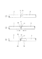
<第1実施形態>
図1は、本発明のガイドワイヤの第1実施形態を示す縦断面図、図2は、図1に示すガイドワイヤにおける第1ワイヤと第2ワイヤとを接続する手順を示す図である。なお、説明の都合上、図1中の右側を「基端」、左側を「先端」という。また、図1中では、見易くするため、ガイドワイヤの長さ方向を短縮し、ガイドワイヤの太さ方向を誇張して模式的に図示したものであり、長さ方向と太さ方向の比率は実際とは大きく異なる(後述する図5〜7についても同様)。
【0033】
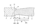
図1に示すガイドワイヤ1は、カテーテルに挿入して用いられるカテーテル用ガイドワイヤであって、先端側に配置された第1ワイヤ2と、第1ワイヤ2の基端側に配置された第2ワイヤ3と、螺旋状のコイル4とを有している。ガイドワイヤ1の全長は、特に限定されないが、200〜5000mm程度であるのが好ましい。また、ガイドワイヤ1の外径は、特に限定されないが、通常、0.2〜1.2mm程度であるのが好ましい。
【0034】
第1ワイヤ2は、弾性を有する線材である。第1ワイヤ2の長さは、特に限定されないが、20〜1000mm程度であるのが好ましい。
【0035】
本実施形態では、第1ワイヤ2は、その先端側の部分に、先端方向へ向かって外径が漸減する外径漸減部22を有している。これにより、第1ワイヤ2の外径漸減部22では、剛性(曲げ剛性、ねじり剛性)を先端方向に向かって徐々に減少させることができ、その結果、ガイドワイヤ1は、先端部に良好な柔軟性を得て、血管への追従性、安全性が向上すると共に、折れ曲がり等も防止することができる。
【0036】
なお、図示の構成では、第1ワイヤ2は、そのほぼ全長に渡り先端方向へ向かって外径が連続的に漸減するテーパ状をなしている。第1ワイヤ2のテーパ状部分のテーパ角度は、長手方向に沿って一定でも、長手方向に沿って変化していてもよい。
【0037】
本実施形態では、外径漸減部22は、その外径が先端方向に向かってほぼ一定の減少率で連続的に減少するテーパ状をなしている。換言すれば、外径漸減部22のテーパ角度は、長手方向に沿ってほぼ一定になっている。これにより、外径漸減部22の長手方向に沿った剛性の変化をより緩やか(滑らか)にすることができる。なお、このような構成と異なり、外径漸減部22の先端方向に向かっての外径の減少率(外径漸減部22のテーパ角度)は、長手方向に沿って変化していても良く、例えば、外径の減少率が比較的大きい個所と比較的小さい個所とが複数回交互に繰り返して形成されているようなものでもよい。なお、その場合、外径漸減部22の先端方向に向かっての外径の減少率がゼロになる個所があってもよい。
【0038】
第1ワイヤ2の基端側の部分は、外径が長手方向に沿ってほぼ一定になっている。なお、図示と異なり、第1ワイヤ2は、ほぼ全長に渡り外径が先端方向に向かって漸減するようなもの、すなわち、そのほぼ全体が外径漸減部22になっているようなものでもよい。
【0039】
第1ワイヤ2の構成材料は、特に限定されず、例えば、ステンレス鋼などの各種金属材料を使用することができるが、擬弾性を示す合金(超弾性合金を含む)であるのが好ましく、超弾性合金であるのがより好ましい。超弾性合金は、比較的柔軟であるとともに復元性があり、曲がり癖が付き難いので、第1ワイヤ2を超弾性合金で構成することにより、ガイドワイヤ1は、その先端側の部分に十分な柔軟性と曲げに対する復元性が得られ、複雑に湾曲・屈曲する血管に対する追従性が向上し、より優れた操作性が得られるとともに、第1ワイヤ2が湾曲・屈曲変形を繰り返しても、第1ワイヤ2に復元性により曲がり癖が付かないので、ガイドワイヤ1の使用中に第1ワイヤ2に曲がり癖が付くことによる操作性の低下を防止することができる。
【0040】
擬弾性合金には、引張りによる応力−ひずみ曲線がいずれの形状のものも含み、As、Af、Ms、Mf等の変態点が顕著に測定できるものも、できないものも含み、応力により大きく変形(歪)し、応力の除去により元の形状にほぼ戻るものは全て含まれる。
【0041】
超弾性合金の好ましい組成としては、49〜52原子%NiのNi−Ti合金等のNi−Ti系合金、38.5〜41.5重量%ZnのCu−Zn合金、1〜10重量%XのCu−Zn−X合金(Xは、Be、Si、Sn、Al、Gaのうちの少なくとも1種)、36〜38原子%AlのNi−Al合金等が挙げられる。このなかでも特に好ましいものは、上記のNi−Ti系合金である。
【0042】
第1ワイヤ2の基端部には、第2ワイヤ3の先端部が連結(接続)されている。第2ワイヤ3は、弾性を有する線材である。第2ワイヤ3の長さは、特に限定されないが、20〜4800mm程度であるのが好ましい。
【0043】
第2ワイヤ3は、第1ワイヤ2の構成材料より弾性率(ヤング率(縦弾性係数)、剛性率(横弾性係数)、体積弾性率)が大きい材料で構成されている。これにより、第2ワイヤ3に適度な剛性(曲げ剛性、ねじり剛性)が得られ、ガイドワイヤ1がいわゆるコシの強いものとなって押し込み性およびトルク伝達性が向上し、より優れた挿入操作性が得られる。
【0044】
また、第1ワイヤおよび/または第2ワイヤは、異なる材料にて内・外層を形成する等、いわゆる複合材料にて構成され得る。このような場合においても、第1ワイヤよりも第2ワイヤの剛性のほうが高いことが好ましい。
【0045】
第2ワイヤ3の構成材料(素材)は、特に限定されず、ステンレス鋼(例えば、SUS304、SUS303、SUS316、SUS316L、SUS316J1、SUS316J1L、SUS405、SUS430、SUS434、SUS444、SUS429、SUS430F、SUS302等のSUS全品種)、ピアノ線、コバルト系合金、擬弾性合金などの各種金属材料を使用することができる。
【0046】
この中でも、コバルト系合金は、ワイヤとしたときの弾性率が高く、かつ適度な弾性限度を有している。このため、コバルト系合金で構成された第2ワイヤ3は、特に優れたトルク伝達性を有し、座屈等の問題を極めて生じ難い。コバルト系合金としては、構成元素としてCoを含むものであれば、いかなるものを用いてもよいが、Coを主成分として含むもの(Co基合金:合金を構成する元素中で、Coの含有率が重量比で最も多い合金)が好ましく、Co−Ni−Cr系合金を用いるのがより好ましい。このような組成の合金を、第2ワイヤ3の構成材料として用いることにより、前述した効果がさらに顕著なものとなる。また、このような組成の合金は、常温における変形においても可塑性を有するため、例えば、使用時等に所望の形状に容易に変形することができる。また、このような組成の合金は、弾性係数が高く、かつ高弾性限度としても冷間成形可能で、高弾性限度であることにより、座屈の発生を十分に防止しつつ、小径化することができ、所定部位に挿入するのに十分な柔軟性と剛性を備えるものとすることができる。
【0047】
Co−Ni−Cr系合金としては、例えば、28〜50wt%Co−10〜30wt%Ni−10〜30wt%Cr−残部Feの組成からなる合金や、その一部が他の元素(置換元素)で置換された合金等が好ましい。置換元素の含有は、その種類に応じた固有の効果を発揮する。例えば、置換元素として、Ti、Nb、Ta、Be、Moから選択される少なくとも1種を含むことにより、第2ワイヤ3の強度のさらなる向上等を図ることができる。なお、Co、Ni、Cr以外の元素を含む場合、その(置換元素全体の)含有量は30wt%以下であるのが好ましい。
また、Co、Ni、Crの一部は、他の元素で置換してもよい。例えば、Niの一部をMnで置換してもよい。これにより、例えば、加工性のさらなる改善等を図ることができる。また、Crの一部をMoおよび/またはWで置換してもよい。これにより、弾性限度のさらなる改善等を図ることができる。Co−Ni−Cr系合金の中でも、Moを含む、Co−Ni−Cr−Mo系合金が特に好ましい。
【0048】
Co−Ni−Cr系合金の具体的な組成としては、例えば、▲1▼40wt%Co−22wt%Ni−25wt%Cr−2wt%Mn−0.17wt%C−0.03wt%Be−残部Fe、▲2▼40wt%Co−15wt%Ni−20wt%Cr−2wt%Mn−7wt%Mo−0.15wt%C−0.03wt%Be−残部Fe、▲3▼42wt%Co−13wt%Ni−20wt%Cr−1.6wt%Mn−2wt%Mo−2.8wt%W−0.2wt%C−0.04wt%Be−残部Fe、▲4▼45wt%Co−21wt%Ni−18wt%Cr−1wt%Mn−4wt%Mo−1wt%Ti−0.02wt%C−0.3wt%Be−残部Fe、▲5▼34wt%Co−21wt%Ni−14wt%Cr−0.5wt%Mn−6wt%Mo−2.5wt%Nb−0.5wt%Ta−残部Fe等が挙げられる。本発明でいうCo−Ni−Cr系合金とはこれらの合金を包含する概念である。
【0049】
また、第2ワイヤ3の構成材料として、ステンレス鋼を用いた場合、ガイドワイヤ1は、より優れた押し込み性およびトルク伝達性が得られる。
【0050】
また、本発明では、第1ワイヤ2と第2ワイヤ3とを異種の合金で構成することが好ましく、また、第1ワイヤ2が、第2ワイヤ3の構成材料より弾性率が小さい材料で構成されたものであるのが好ましい。これにより、ガイドワイヤ1は、先端側の部分が優れた柔軟性を有するとともに、基端側の部分が剛性(曲げ剛性、ねじり剛性)に富んだものとなる。その結果、ガイドワイヤ1は、優れた押し込み性やトルク伝達性を得て良好な操作性を確保しつつ、先端側においては良好な柔軟性、復元性を得て血管への追従性、安全性が向上する。
【0051】
また、第1ワイヤ2と、第2ワイヤ3との具体的な組合せとしては、第1ワイヤ2を超弾性合金で構成し、第2ワイヤ3をCo−Ni−Cr系合金またはステンレス鋼で構成することが特に好ましい。これにより、前述した効果はさらに顕著なものとなる。
【0052】
また、第1ワイヤ2を構成する超弾性合金としてNi−Ti系合金を用いることが、先端側の柔軟性と復元性の点から好ましい。
【0053】
コイル4は、線材(細線)を螺旋状に巻回してなる部材であり、第1ワイヤ2の先端側の部分を覆うように設置されている。図示の構成では、第1ワイヤ2の先端側の部分は、コイル4の内側のほぼ中心部に挿通されている。また、第1ワイヤ2の先端側の部分は、コイル4の内面と非接触で挿通されている。なお、図示の構成では、コイル4は、外力を付与しない状態で、螺旋状に巻回された線材同士の間にやや隙間が空いているが、図示と異なり、外力を付与しない状態で、螺旋状に巻回された線材同士が隙間なく密に配置されていてもよい。
【0054】
コイル4は、金属材料で構成されているのが好ましい。コイル4を構成する金属材料としては、例えば、ステンレス鋼、超弾性合金、コバルト系合金や、金、白金、タングステン等の貴金属またはこれらを含む合金等が挙げられる。特に、貴金属のようなX線不透過材料で構成した場合には、ガイドワイヤ1にX線造影性が得られ、X線透視下で先端部の位置を確認しつつ生体内に挿入することができ、好ましい。また、コイル4は、その先端側と基端側とを異なる材料で構成しても良い。例えば、先端側をX線不透過材料のコイル、基端側をX線を比較的透過する材料(ステンレス鋼など)のコイルにて各々構成しても良い。なお、コイル4の全長は、特に限定されないが、5〜500mm程度であるのが好ましい。
【0055】
コイル4の基端部および先端部は、それぞれ、固定材料11および12により第1ワイヤ2に固定されている。また、コイル4の中間部(先端寄りの位置)は、固定材料13により第1ワイヤ2に固定されている。固定材料11、12および13は、半田(ろう材)で構成されている。なお、固定材料11、12および13は、半田に限らず、接着剤でもよい。また、コイル4の固定方法は、固定材料によるものに限らず、例えば、溶接でもよい。また、血管内壁の損傷を防止するために、固定材料12の先端面は、丸みを帯びているのが好ましい。
【0056】
本実施形態では、このようなコイル4が設置されていることにより、第1ワイヤ2は、コイル4に覆われて接触面積が少ないので、摺動抵抗を低減することができ、よって、ガイドワイヤ1の操作性がより向上する。
【0057】
なお、本実施形態の場合、コイル4は、線材の横断面が円形のものを用いているが、これに限らず、線材の断面が例えば楕円形、四角形(特に長方形)等のものであってもよい。
【0058】
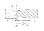
このガイドワイヤ1では、第1ワイヤ2と、第2ワイヤ3とは、溶接により互いに連結(固定)されている。これにより、第1ワイヤ2と第2ワイヤ3との溶接部(接続部)14は、高い結合強度(接合強度)が得られ、よって、ガイドワイヤ1は、第2ワイヤ3からのねじりトルクや押し込み力が確実に第1ワイヤ2に伝達される。
【0059】
本実施形態では、第1ワイヤ2の第2ワイヤ3に対する接続端面21と、第2ワイヤ3の第1ワイヤ2に対する接続端面31は、それぞれ、両ワイヤの軸方向(長手方向)にほぼ垂直な平面になっている。これにより、接続端面21、31を形成するための加工が極めて容易であり、ガイドワイヤ1の製造工程を複雑化することなく上記効果を達成することができる。
【0060】
なお、図示の構成と異なり、接続端面21、31は、両ワイヤの軸方向(長手方向)に垂直な平面に対し傾斜していてもよく、また、凹面または凸面になっていてもよい。
【0061】
第1ワイヤ2と、第2ワイヤ3との溶接の方法としては、特に限定されず、例えば、レーザを用いたスポット溶接、バットシーム溶接等の突き合わせ抵抗溶接などが挙げられるが、突き合わせ抵抗溶接であるのが好ましい。これにより、溶接部14は、より高い結合強度が得られる。
【0062】
このようなガイドワイヤ1では、第2ワイヤ3は、溶接部14付近に、その横断面積が第1ワイヤ2の基端部23の横断面積より小さい小横断面積部32を有している。換言すれば、第2ワイヤ3は、接続端面31から、その基端側の所定の位置までの部分(小横断面積部32)の横断面積が第1ワイヤ2の基端部23の横断面積より小さくなっている。本実施形態では、小横断面積部32は、その外径が第1ワイヤ2の基端部23の外径より小さくなっていることにより、その横断面積が基端部23の横断面積より小さくなっている。すなわち、接続端面31の面積は、接続端面21の面積より小さい。
【0063】
前述したように、第2ワイヤ3は、第1ワイヤ2より弾性率が大きい材料で構成されているので、仮に第2ワイヤ3の先端部の外径が第1ワイヤ2の基端部23の外径と同じであった場合には、溶接部14を挟んでガイドワイヤ1の剛性(曲げ剛性、ねじり剛性)が急激に変化する。これに対し、本発明では、第2ワイヤ3の先端部に小横断面積部32を設け、小横断面積部32での剛性(曲げ剛性、ねじり剛性)を小さくした(低下させた)ことにより、溶接部14を含むその付近の部位での剛性(曲げ剛性、ねじり剛性)の長手方向に沿った変化を緩やか(滑らか)にすることができ、ガイドワイヤ1は、優れた操作性が得られる。
【0064】
また、本実施形態では、小横断面積部32は、小横断面積部32のその外径が先端方向へ向かって漸減する部分、すなわち、その横断面積が先端方向へ向かって漸減する部分を有している。これにより、小横断面積部32の基端から小横断面積部32の先端までの間で剛性(曲げ剛性、ねじり剛性)を先端方向に向かって漸減させることができ、その結果、ガイドワイヤ1は、剛性(曲げ剛性、ねじり剛性)の長手方向に沿った変化をより緩やか(滑らか)にすることができる。
【0065】
なお、図示の構成では、小横断面積部32は、その全長に渡り外径(横断面積)が先端方向へ向かって漸減するテーパ状をなしているが、小横断面積部32は、例えばその先端部に外径(横断面積)が一定の部分があってもよく、さらには、この外径が一定の部分の先端側に、外径が溶接部14に向かって漸増する部分があってもよく、これらの場合でも、上記と同様の効果が得られる。これらの構成の具体例については、後に詳述する。
【0066】
小横断面積部32の長さ(図1中のLで示す長さ)は、特に限定されないが、3〜1000mm程度であるのが好ましく、3〜300mm程度であるのがより好ましい。Lが前記範囲にあると、溶接部14を含むその付近の部位において、長手方向に沿った剛性(曲げ剛性、ねじり剛性)の変化をより緩やか(滑らか)にすることができる。
【0067】
また、小横断面積部32は、第2ワイヤ3の先端(接続端面31)における曲げ剛性が、第1ワイヤ2の基端(接続端面21)における曲げ剛性にほぼ等しくなるように形成されているのが好ましい。これにより、溶接部14を含むその付近の部位において、長手方向に沿った剛性の変化をより緩やか(滑らか)にすることができる。なお、第2ワイヤ3の先端における曲げ剛性は、接続端面31の断面2次モーメント(接続端面31の形状、寸法のみから定まる)をI2とし、第2ワイヤ3の構成材料のヤング率をE2としたとき、E2I2で得られ、第1ワイヤ2の基端における曲げ剛性は、接続端面21の断面2次モーメント(接続端面21の形状、寸法のみから定まる)をI1とし、第1ワイヤ2の構成材料のヤング率をE1としたとき、E1I1で得られる。
【0068】
また、本実施形態のガイドワイヤ1は、溶接部14の外周に形成される段差を埋める段差埋め部材6を有している。これにより、第1ワイヤ2の基端の外径より第2ワイヤ3の先端の外径が小さいことにより形成される溶接部14の外周の段差が解消されるので、この段差によるガイドワイヤ1の摺動性の低下を防止することができる。
【0069】
図示の構成では、段差埋め部材6は、小横断面積部32の外周を覆い、その外径が長手方向に沿ってほぼ一定であるとともにその内径が先端方向に向かって漸減していることにより、溶接部14および小横断面積部32を含むその付近におけるガイドワイヤ1の外径を長手方向に沿ってほぼ一定にするような形状をなしている。これにより、段差がガイドワイヤ1の摺動性に与える影響をより確実に解消することができる。
【0070】
段差埋め部材6の構成材料としては、特に限定されず、例えば、各種樹脂材料、各種金属材料を用いることができるが、ガイドワイヤ1の剛性への寄与が少ないように、比較的柔軟な材料(例えば、半田、プラスティック、ろう等)であるのが好ましい。また、段差埋め部材6の形態は、図示の構成に限らず、例えば、コイル状の部材であってもよい。
【0071】
なお、本実施形態では、溶接部14は、コイル4の基端よりも基端側に位置しているが、図示と異なり、溶接部14がコイル4の基端よりも先端側に位置していても良い。
【0072】
また、第1ワイヤの剛性が第2ワイヤの剛性より弱い場合、図1中の接続端面31、21の大きさが逆の場合もある。
【0073】
図5および図6は、それぞれ、本発明のガイドワイヤにおける小横断面積部の他の構成例を示す縦断面図である。
【0074】
図5に示すように、小横断面積部32は、その外径が先端方向へ向かって漸減する第1の部分32Aと、第1の部分32Aより先端側に位置し、その外径が先端方向へ向かって漸増する第2の部分32Bとを有している。第1の部分32Aと第2の部分32Bとの境界部の外周面は、段差のない連続した湾曲面(なだらかな面)を構成している。このような構成としたことにより、当該境界部への応力集中が防止または緩和され、ねじれやキンクがより確実に防止される(耐キンク性が向上する)。
【0075】
第2の部分32Bの最大外径は、その先端の接続端面31にあり、この最大外径は、第1ワイヤ2の基端(接続端面21)の外径にほぼ等しい。すなわち、図5に示す小横断面積部32では、図1に示す構成に比べ、溶接部14の溶接面の面積をより大きくすることができ、溶接強度を向上することができる。その結果、第2ワイヤ3から第1ワイヤ2へねじりトルクや押し込み力が作用した際に、溶接部14への応力集中や強度不足による溶接部14の破損をより確実に防止することができる。
【0076】
また、このような小横断面積部32において、第1の部分32Aの長さをLA、第2の部分32Bの長さをLBとしたとき、LAはLBより大きい。すなわち、第1の部分32Aのテーパ角度は、第2の部分32Bのテーパ角度より小さい。
【0077】
具体的には、第1の部分32Aの長さLAは、第2の部分32Bの長さLBの0.1〜1000倍程度であるのが好ましく、1.0〜1000倍程度であるのがより好ましく、1.0〜50倍程度であるのがさらに好ましい。このような条件とすることにより、溶接部14への応力集中を抑制し、スムーズな剛性移行を実現できる。
【0078】
図6に示す小横断面積部32は、第1の部分32Aと第2の部分32Bとの間に、その外径がほぼ一定の第3の部分32Cを有し、それ以外は、前記図5に示す構成と同様である。この第3の部分32Cの外径は、小横断面積部32の中で、最も小径の部分となる。
【0079】
この図6に示す小横断面積部32も、前記図5に示す小横断面積部32と同様の作用・効果を有するが、特に、第3の部分32Cを設けたことにより、小横断面積部32中での最小径部分が一定の長さ(下記LC)連続して存在することとなるため、図5に示す構成に比べ、小横断面積部32中の最小径部分への応力集中が緩和または分散され、その結果、第2ワイヤ3から第1ワイヤ2へねじりトルクや押し込み力が作用した際に、小横断面積部32中の最小径部分のねじれ、キンク、破損等をより確実に防止することができる。
【0080】
なお、第3の部分32Cは、第1ワイヤ2の基端部23付近とほぼ同じ剛性を有することが好ましい。また、第3の部分32Cの外径は、第1ワイヤ2の基端部23付近とほぼ同じ剛性を有するような外径であるので、小横断面積部32から第1ワイヤ2の基端部23へスムーズな剛性の移行が実現される。
【0081】
第1の部分32Aと第3の部分32Cとの境界部の外周面および第3の部分32Cと第2の部分32Bとの境界部の外周面は、それぞれ、段差のない連続した湾曲面(なだらかな面)を構成している。これにより、前記と同様の効果が得られる。
【0082】
第1の部分32Aの長さLAと、第2の部分32Bの長さLBの好ましい関係は、前記と同様である。また、これらと第3の部分32Cの長さLCとの関係は、特に限定されないが、LB≦LC≦LAまたはLB≦LA≦LCとするのが好ましい。
【0083】
さらに、本実施形態において、第1の部分32Aの長さLAは、第2の部分32Bの長さLBの0.1〜1000倍程度であるのが好ましく、0.1〜10倍程度であるのがより好ましい。このような条件とすることにより、溶接部14への応力集中を抑制し、スムーズな剛性移行を実現できる。
【0084】
また、小横断面積部32の強度を維持しつつ、最小径部分への応力集中の緩和または分散効果を十分に得るために、第3の部分32Cの長さLCは、0.1〜200mm程度であるのが好ましく、1〜50mm程度であるのがより好ましい。
【0085】
なお、図5および図6に示す小横断面積部32においても、小横断面積部32の外周を前述の段差埋め部材6で覆ってもよく、これにより、前記と同様の効果が得られる。
【0086】
以下、図2を参照して、第1ワイヤ2と第2ワイヤ3とを突き合わせ抵抗溶接の一例であるバットシーム溶接により接合する場合の手順について説明する。同図には、第1ワイヤ2と第2ワイヤ3とをバットシーム溶接により接合する場合の手順▲1▼〜▲3▼が示されている。
【0087】
手順▲1▼では、図示しないバット溶接機に固定(装着)された第1ワイヤ2と第2ワイヤ3とが示される。
【0088】
手順▲2▼にて、第1ワイヤ2と第2ワイヤ3とは、バット溶接機によって、所定の電圧を印加されながら第1ワイヤ2の基端側の接続端面21と第2ワイヤ3の先端側の接続端面31とが加圧接触される。この加圧接触により、接触部分には溶融層が形成され、第1ワイヤ2と第2ワイヤ3とは強固に接続される。
【0089】
手順▲3▼にて、加圧接触することによって変形された接続箇所(溶接部14)の突出部分を削除する。次いで、第2ワイヤ3の溶接部14の基端側の部分、すなわち第2ワイヤ3の先端部を研磨して、例えば図1、図5または図6に示すような所望の形状の小横断面積部32、すなわち外径が先端方向に向かって漸減するまたはこのような部分を有する小横断面積部32を形成する。
【0090】
なお、予め第2ワイヤ3の先端部を研磨して所望の形状の(外径が先端方向に向かって漸減するまたはこのような部分を有する)小横断面積部32を形成したものを、第1ワイヤ2と加圧接触させて溶接しても良い。
【0091】
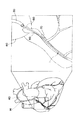
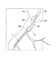
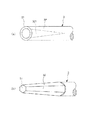
図3および図4は、それぞれ、本発明のガイドワイヤ1をPTCA術に用いた場合における使用状態を示す図である。
【0092】
図3および図4中、符号40は大動脈弓、符号50は心臓の右冠状動脈、符号60は右冠状動脈開口部、符号70は血管狭窄部である。また、符号30は大腿動脈からガイドワイヤ1を確実に右冠状動脈に導くためのガイディングカテーテル、符号20はその先端部分に拡張・収縮自在なバルーン201を有する狭窄部拡張用のバルーンカテーテルである。
【0093】
図3に示すように、ガイドワイヤ1の先端をガイディングカテーテル30の先端から突出させ、右冠状動脈開口部60から右冠状動脈50内に挿入する。さらに、ガイドワイヤ1を進め、先端から右冠状動脈内に挿入し、先端が血管狭窄部70を超えた位置で停止する。これにより、バルーンカテーテル20の通路が確保される。なお、このとき、ガイドワイヤ1の溶接部14は、大動脈弓40の基部付近(生体内)に位置している。
【0094】
次に、図4に示すように、ガイドワイヤ1の基端側から挿通されたバルーンカテーテル20の先端をガイディングカテーテル30の先端から突出させ、さらにガイドワイヤ1に沿って進め、右冠状動脈開口部60から右冠状動脈50内に挿入し、バルーンが血管狭窄部70の位置に到達したところで停止する。
【0095】
次に、バルーンカテーテル20の基端側からバルーン拡張用の流体を注入して、バルーン201を拡張させ、血管狭窄部70を拡張する。このようにすることによって、血管狭窄部70の血管に付着堆積しているコレステロール等の堆積物は物理的に押し広げられ、血流阻害が解消できる。
【0096】
<第2実施形態>
図7は、本発明のガイドワイヤの第2実施形態を示す縦断面図である。以下、この図を参照して本発明のガイドワイヤの第2実施形態について説明するが、前述した実施形態との相違点を中心に説明し、同様の事項についてはその説明を省略する。
【0097】
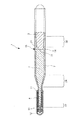
本実施形態のガイドワイヤ1’では、第1ワイヤ2が、外径漸減部22と該外径漸減部22より基端側に設けられた外径漸減部24とを有している。このように、第1ワイヤ2には、複数の部位に外径漸減部が形成されていてもよい。
【0098】
また、本実施形態では、溶接部14に、外周方向に突出する突出部15が形成されている。このような突出部15が形成されることにより、第1ワイヤ2と、第2ワイヤ3との接合面積が大きくなり、これらの接合強度は、特に高いものとなる。これにより、ガイドワイヤ1’は、第2ワイヤ3からのねじりトルクや押し込み力がより確実に第1ワイヤ2に伝達される。
【0099】
また、突出部15が形成されることにより、例えば、X線透視下で、第1ワイヤ2と第2ワイヤ3との溶接部14をより容易に視認することが可能となる。その結果、X線透視像を確認することにより、血管内などにおけるガイドワイヤ1’、カテーテルの進行状況を容易かつ確実に把握することができ、施術時間の短縮、安全性の向上に寄与することができる。
【0100】
また、上述したように、第1ワイヤ2、第2ワイヤ3は、通常、異なる弾性率を有する材料で構成されている。このため、突出部15が設けられることにより、術者が、ガイドワイヤ1’の弾性率が比較的大きく変化する部位を容易かつ確実に認識することが可能となる。その結果、ガイドワイヤ1’は、操作性に優れたものとなり、施術時間の短縮、安全性の向上に寄与することができる。
【0101】
突出部15の高さは、第1ワイヤ2や第2ワイヤ3の外径によるので特に限定されないが、0.001〜0.3mmであるのが好ましく、0.005〜0.05mmであるのがより好ましい。突出部15の高さが前記下限値未満であると、第1ワイヤ2、第2ワイヤ3の構成材料などによっては、前述した効果が十分に発揮されない可能性がある。一方、突出部15の高さが前記上限値を超えると、バルーンカテーテルに挿入するルーメンの内径が決まっているので、突出部15の高さと比較して、基端側の第2ワイヤ3の外径を細くせざるを得なくなり、第2ワイヤ3の物性を十分に発揮するのが困難になる場合がある。
【0102】
図7に示す構成では、突出部15は、その縦断面における一方側(図7中上側)およびその反対側(図7中下側)の輪郭形状がそれぞれ略円弧状をなし、突出部15の最大外径部に溶接部14が位置している。これにより、溶接部14の溶接面の面積を大きくとることができ、より高い結合強度(溶接強度)が得られるという利点がある。
【0103】
ただし、本発明では、突出部15の形状および突出部15に対する溶接部14の位置はこれに限定されないことは、言うまでもない。例えば、突出部15は、縦断面における一方側およびその反対側の輪郭形状がそれぞれ、例えば台形、三角形等の非円形(非円弧形状)でもよい。また、突出部15は、溶接部14の溶接面(接続端面21、31)を境に基端側と先端側とが非対称の形状をなしていてもよい。また、突出部15は、突出部15に対する溶接部14の溶接面の軸方向の位置が、図7に示すような中央部ではなく、基端側(第2ワイヤ3側)あるいは先端側(第1ワイヤ2側)に偏った位置にあるものでもよい。このような構成とすることにより、溶接部14への応力集中を防止または緩和することができ、よって、第2ワイヤ3から第1ワイヤ2へねじりトルクや押し込み力が作用した際に、溶接部14への応力集中による溶接部14の破損をより確実に防止することができる。
【0104】
また、本実施形態のガイドワイヤ1’では、その外表面(外周面)側に、被覆層7を有している。このように、本発明のガイドワイヤは、その外表面(外周面)の全部または一部を覆う被覆層を有するものであってもよい。このような被覆層7は、種々の目的で形成することができるが、その一例として、ガイドワイヤ1’の摩擦(摺動摩擦)を低減し、摺動性を向上させることによってガイドワイヤ1’の操作性を向上させることがある。
【0105】
このような目的のためには、被覆層7は、摩擦を低減し得る材料で構成されているのが好ましい。これにより、ガイドワイヤ1’とともに用いられるカテーテルの内壁との摩擦抵抗(摺動抵抗)が低減されて摺動性が向上し、カテーテル内でのガイドワイヤ1’の操作性がより良好なものとなる。また、ガイドワイヤ1’の摺動抵抗が低くなることで、ガイドワイヤ1’をカテーテル内で移動および/または回転した際に、ガイドワイヤ1’のキンク(折れ曲がり)やねじれ、特に溶接部付近におけるキンクやねじれをより確実に防止することができる。
【0106】
このような摩擦を低減し得る材料としては、例えば、ポリエチレン、ポリプロピレン等のポリオレフィン、ポリ塩化ビニル、ポリエステル(PET、PBT等)、ポリアミド、ポリイミド、ポリウレタン、ポリスチレン、ポリカーボネート、シリコーン樹脂、フッ素系樹脂(PTFE、ETFE等)、シリコーンゴム、その他各種のエラストマー(例えば、ポリアミド系、ポリエステル系等の熱可塑性エラストマー)またはこれらの複合材料が挙げられるが、そのなかでも特に、フッ素系樹脂(またはこれを含む複合材料)が好ましく、PTFEがより好ましい。
【0107】
また、摩擦を低減し得る材料の他の好ましい例としては、親水性材料または疎水性材料が挙げられる。これらのうちでも特に、親水性材料が好ましい。
【0108】
この親水性材料としては、例えば、セルロース系高分子物質、ポリエチレンオキサイド系高分子物質、無水マレイン酸系高分子物質(例えば、メチルビニルエーテル−無水マレイン酸共重合体のような無水マレイン酸共重合体)、アクリルアミド系高分子物質(例えば、ポリアクリルアミド、ポリグリシジルメタクリレート−ジメチルアクリルアミド(PGMA−DMAA)のブロック共重合体)、水溶性ナイロン、ポリビニルアルコール、ポリビニルピロリドン等が挙げられる。
【0109】
このような親水性材料は、多くの場合、湿潤(吸水)により潤滑性を発揮し、ガイドワイヤ1’とともに用いられるカテーテルの内壁との摩擦抵抗(摺動抵抗)を低減する。これにより、ガイドワイヤ1’の摺動性が向上し、カテーテル内でのガイドワイヤ1’の操作性がより良好なものとなる。
【0110】
また、このような被覆層7が設けられることにより、前述した段差埋め部材6を省略または簡略化することもできる。すなわち、被覆層7は、溶接部14付近の段差を覆い隠すように形成されるので、段差埋め部材6を省略または簡略化した場合であっても、前記段差によるガイドワイヤ1’の摺動性の低下を十分に防止することができる。
【0111】
このような被覆層7の形成箇所は、ガイドワイヤ1’の全長でも、長手方向の一部でもよいが、溶接部14を覆うように、すなわち溶接部14を含む箇所に形成されているのが好ましい。
【0112】
被覆層7は、小横断面積部32および突出部15を被覆して、実質的に均一な外径になっている。なお、使用上支障のないようななだらかな外径の変化も「実質的に均一な外径」に含むものとする。
【0113】
被覆層7の厚さは、特に限定されないが、通常は、厚さ(平均)が1〜20μm程度であるのが好ましく、2〜10μm程度であるのがより好ましい。被覆層7の厚さが薄すぎると、被覆層7の形成目的が十分に発揮されないことがあり、また、被覆層7の剥離が生じるおそれがあり、また、被覆層7の厚さが厚すぎると、ワイヤの物性を阻害することがあり、また被覆層7の剥離が生じるおそれがある。
【0114】
なお、本発明では、ガイドワイヤ本体(第1ワイヤ2、第2ワイヤ3、コイル4等)の外周面(表面)に、被覆層7の密着性を向上するための処理(化学処理、熱処理等)を施したり、被覆層7の密着性を向上し得る中間層を設けたりすることもできる。
【0115】
また、被覆層7は、各部位でほぼ一定の組成を有するものであってもよいし、異なる組成を有するものであってもよい。例えば、被覆層7は、少なくともコイル4を被覆する領域(第1被覆層)と、該領域より基端側の領域(第2被覆層)とで、構成材料が異なるものであってもよい。また、第1被覆層、第2被覆層は、図示のように、両者が長手方向に連続して形成されたものであってもよいが、第1被覆層の基端と第2被覆層の先端とが離間していてもよく、あるいは、第1被覆層と第2被覆層とが部分的に重なっていてもよい。
【0116】
図8は、本発明のガイドワイヤにおける第2ワイヤの小横断面積部の他の構成例を示す斜視図である。
【0117】
図8(a)に示す第2ワイヤ3の小横断面積部32は、その外径が縮径しておらず、小横断面積部32より基端側の部分と外径が同じになっている。この小横断面積部32は、中空部321を有しており、この中空部321の内径は、先端方向に向かって漸増している。すなわち、中空部321は、円錐(または円錐台)のような形状になっている。このような中空部321が形成されていることにより、小横断面積部32は、第1ワイヤ2の基端部23より横断面積が小さいと共に、先端方向に向かって横断面積が漸減しており、その剛性(曲げ剛性、ねじり剛性)も先端方向に向かって漸減している。本発明では、小横断面積部32がこの図8(a)に示す形態のような場合でも、前述した実施形態と同様の効果が得られる。さらに、中空部321を形成し、外径を変化させないで横断面積を小さくしたことにより、段差埋め部材6を設けなくても、第1ワイヤ2の基端部23との溶接部14に段差が生じないという利点もある。なお、中空部321は、角錐(または角錐台)のような形状であっても良い。また、この場合、第2ワイヤ3の中空部321内に第1ワイヤ2の基端部23の一部が挿入するように溶接されることにより、溶接部14前後の剛性がより滑らかに変化するので、耐キンク性がより向上する。
【0118】
図8(b)に示す第2ワイヤ3の小横断面積部32は、角錐台(6角錐台)のような形状になっており、その横断面の多角形(正6角形)の大きさが先端方向に向かって徐々に小さくなることにより、先端方向に向かって横断面積が漸減しており、その剛性(曲げ剛性、ねじり剛性)も先端方向に向かって漸減している。小横断面積部32がこの図8(b)に示す形態のような場合でも、前述した実施形態と同様の効果が得られる。
【0119】
以上、本発明のガイドワイヤを図示の実施形態について説明したが、本発明は、これに限定されるものではなく、ガイドワイヤを構成する各部は、同様の機能を発揮し得る任意の構成のものと置換することができる。また、任意の構成物が付加されていてもよい。
【0120】
【発明の効果】
以上述べたように、本発明によれば、先端側に配置された第1ワイヤと、第1ワイヤの基端側に配置され、第1ワイヤより弾性率の大きい材料で構成された第2ワイヤとを設けたことにより、柔軟性に優れた先端部と剛性に富んだ基端部とを有し、押し込み性、トルク伝達性および追従性に優れたガイドワイヤが構成できる。
【0121】
また、第1ワイヤと第2ワイヤとを溶接により連結したことにより、連結部(溶接部)の結合強度が高く、第2ワイヤから第1ワイヤへねじりトルクや押し込み力を確実に伝達することができる。
【0122】
また、第2ワイヤに小横断面積部を設けたことにより、溶接部を含むその付近の部位の長手方向に沿った剛性変化が穏やかであり、溶接部付近におけるキンク(折れ曲がり)やねじれを確実に防止することができる。
【0123】
特に、小横断面積部の形状を工夫すること、例えば、前記第1の部分と第2の部分、さらには第3の部分を設けることにより、溶接部の溶接強度を高めるとともに、小横断面積部における局所的な応力集中を緩和または分散し、キンクやねじれをより確実に防止することができる。
【0124】
このようなことから、本発明によれば、操作性および耐キンク性、耐ねじれ性に優れたガイドワイヤを提供することができる。
【0125】
また、溶接部に突出部を形成することにより、連結部(溶接部)の結合強度をさらに高いものとし、第2ワイヤから第1ワイヤへねじりトルクや押し込み力をより確実に伝達することが可能となる。
【0126】
また、被覆層が摩擦を低減し得る材料で構成されている場合には、カテーテル内などにおけるガイドワイヤの摺動性が向上し、ガイドワイヤの操作性をより良好なものとすることができる。ガイドワイヤの摺動抵抗が低くなることで、ガイドワイヤのキンク(折れ曲がり)やねじれ、特に溶接部付近におけるキンクやねじれをより確実に防止することができる。
【0127】
また、各部位で、被覆層の構成材料を変更すること等により、部分的に摺動抵抗を高めた部位を設けることができ、術者においては、ガイドワイヤの汎用性が広くなる。
【図面の簡単な説明】
【図1】本発明のガイドワイヤの第1実施形態を示す縦断面図である。
【図2】図1に示すガイドワイヤにおける第1ワイヤと第2ワイヤとを接続する手順を示す図である。
【図3】本発明のガイドワイヤの使用例を説明するための模式図である。
【図4】本発明のガイドワイヤの使用例を説明するための模式図である。
【図5】本発明のガイドワイヤにおける小横断面積部の他の構成例を示す縦断面図である。
【図6】本発明のガイドワイヤにおける小横断面積部の他の構成例を示す縦断面図である。
【図7】本発明のガイドワイヤの第2実施形態を示す縦断面図である。
【図8】本発明のガイドワイヤにおける第2ワイヤの小横断面積部の他の構成例を示す斜視図である。
【符号の説明】
1、1’ ガイドワイヤ
2 第1ワイヤ
21 接続端面
22 外径漸減部
23 基端部
24 外径漸減部
3 第2ワイヤ
31 接続端面
32 小横断面積部
32A 第1の部分
32B 第2の部分
32C 第3の部分
321 中空部
4 コイル
6 段差埋め部材
7 被覆層
11、12、13 固定材料
14 溶接部
15 突出部
20 バルーンカテーテル
201 バルーン
30 ガイディングカテーテル
40 大動脈弓
50 右冠状動脈
60 右冠状動脈開口部
70 血管狭窄部[0001]
TECHNICAL FIELD OF THE INVENTION
The present invention relates to a guidewire, particularly to a guidewire used for introducing a catheter into a body cavity such as a blood vessel.
[0002]
[Prior art]
The guide wire is used for treatment of a site where surgery is difficult, such as PTCA (Percutaneous Transluminal Coronary Angioplasty), treatment for the purpose of minimally invasive to the human body, and treatment of the heart. It is used to guide catheters used for examinations such as angiography. The guide wire used in the PTCA operation is inserted into the vicinity of a target vascular stenosis together with the balloon catheter with the distal end of the guide wire protruding from the distal end of the balloon catheter. Guide to nearby.
[0003]
The blood vessels are intricately curved, and the guide wire used when inserting the balloon catheter into the blood vessels has a moderate flexibility and resilience to bending, and a pushability to transmit the operation at the proximal end to the distal side. And torque transmission properties (collectively referred to as “operability”), as well as kink resistance (bending resistance) and the like. Among these properties, as a structure for obtaining a moderate flexibility, a structure with a metal coil that has flexibility against bending around a thin tip core material of a guide wire, and for imparting flexibility and resilience There is a guide wire using a superelastic wire such as Ni-Ti as a core material.
[0004]
In a conventional guide wire, a core material is substantially composed of one kind of material. In order to enhance the operability of the guide wire, a material having a relatively high elastic modulus is used. Has lost flexibility. If a material having a relatively low elastic modulus is used to obtain the flexibility of the distal end portion of the guide wire, the operability at the proximal end side of the guide wire is lost. Thus, it has been difficult to satisfy the required flexibility and operability with one kind of core material.
[0005]
In order to improve such a defect, for example, a Ni—Ti alloy wire is used as a core material, and heat treatment is performed on the distal side and the proximal side under different conditions to increase the flexibility of the distal end and increase the flexibility of the proximal side. A guide wire with increased rigidity has been proposed (for example, see Patent Document 1). However, there is a limit to the control of flexibility by such heat treatment, and even if sufficient flexibility is obtained at the distal end, satisfactory rigidity may not always be obtained at the proximal end.
[0006]
[Patent Document 1]
JP-A-63-171570
[0007]
[Problems to be solved by the invention]
SUMMARY OF THE INVENTION An object of the present invention is to provide a guidewire which has a gradual change in rigidity in the longitudinal direction of the wire and is excellent in operability and kink resistance.
[0008]
[Means for Solving the Problems]
Such an object is achieved by the present invention described in the following (1) to (11). Further, the following (12) to (22) are preferable.
[0009]
(1) a linear first wire disposed on the distal end side;
A linear second wire, which is disposed on the base end side of the first wire and is made of a material having a higher elastic modulus than the constituent material of the first wire,
The first wire and the second wire are connected by welding,
The second wire has a small cross-sectional area near the weld of the first wire and the second wire, the cross-sectional area of which is smaller than the cross-sectional area of the base end of the first wire. Guide wire.
[0010]
(2) a linear first wire disposed on the distal end side;
A second linear wire disposed on the proximal end side of the first wire and having a higher rigidity than the first wire;
A welding portion where the first wire and the second wire are connected by welding, having a projecting portion projecting in an outer peripheral direction;
The second wire has a small cross-sectional area near the weld of the first wire and the second wire, the cross-sectional area of which is smaller than the cross-sectional area of the base end of the first wire. Guide wire.
[0011]
(3) The guide wire according to the above (1) or (2), further comprising a coating layer provided so as to cover at least the welded portion.
[0012]
(4) The guide wire according to any one of (1) to (3), wherein an outer diameter of the small cross-sectional area is smaller than an outer diameter of a base end of the first wire.
[0013]
(5) The guidewire according to any one of (1) to (4), wherein the small cross-sectional area portion has a portion whose cross-sectional area gradually decreases in a distal direction.
[0014]
(6) The guide wire according to any one of (1) to (5), wherein the small cross-sectional area portion has a portion whose outer diameter gradually decreases in a distal direction.
[0015]
(7) The small cross-sectional area portion has a first portion whose outer diameter gradually decreases in the distal direction, and is located closer to the distal side than the first portion, and the outer diameter gradually increases in the distal direction. The guidewire according to any one of the above (1) to (5), having a second portion.
[0016]
(8) The guide wire according to (7), wherein the small cross-sectional area portion has a third portion having a substantially constant outer diameter between the first portion and the second portion.
[0017]
(9) The guidewire according to (7) or (8), wherein the length of the first portion is 0.1 to 1000 times the length of the second portion.
[0018]
(10) The guide wire according to any one of (1) to (9), wherein a bending rigidity at a distal end of the second wire and a bending rigidity at a proximal end of the first wire are substantially equal.
[0019]
(11) The guidewire according to any one of (1) to (10), further including a step filling member that fills a step formed on the outer periphery of the welded portion.
[0020]
(12) The guide wire according to (7), wherein an outer peripheral surface at a boundary between the first portion and the second portion forms a continuous curved surface without a step.
[0021]
(13) The outer peripheral surface at the boundary between the first portion and the third portion and the outer peripheral surface at the boundary between the third portion and the second portion are each continuously curved without a step. The guidewire according to the above (8), which constitutes a surface.
[0022]
(14) The guide wire according to any of (1) to (13), wherein the first wire is made of a superelastic alloy.
[0023]
(15) The guide wire according to any one of (1) to (14), wherein the second wire is made of stainless steel.
[0024]
(16) The guide wire according to any one of (1) to (15), wherein the second wire is made of a Co-based alloy.
[0025]
(17) The guide wire according to (16), wherein the Co-based alloy is a Co-Ni-Cr-based alloy.
[0026]
(18) The guide wire according to any one of (1) to (17), wherein a connection end face between the first wire and the second wire is substantially perpendicular to an axial direction of both wires.
[0027]
(19) The guide wire according to any one of (1) to (18), further including a spiral coil that covers at least a portion of the first wire on the distal end side.
[0028]
(20) The guide wire according to the above (19), wherein the welded portion is located closer to a base end than a base end of the coil.
[0029]
(21) The guidewire according to any one of (1) to (20), wherein the welding is performed by butt resistance welding.
[0030]
(22) The guidewire according to any one of (1) to (21), wherein the welded portion is used so as to be located in a living body.
[0031]
BEST MODE FOR CARRYING OUT THE INVENTION
Hereinafter, a guidewire of the present invention will be described in detail based on a preferred embodiment shown in the accompanying drawings.
[0032]
<First embodiment>
FIG. 1 is a longitudinal sectional view showing a first embodiment of a guide wire according to the present invention, and FIG. 2 is a view showing a procedure for connecting a first wire and a second wire in the guide wire shown in FIG. For convenience of explanation, the right side in FIG. 1 is referred to as a “base end” and the left side is referred to as a “distal end”. Also, in FIG. 1, the length direction of the guide wire is shortened to make it easier to see, and the thickness direction of the guide wire is schematically exaggerated, and the ratio of the length direction to the thickness direction is This is significantly different from the actual case (the same applies to FIGS. 5 to 7 described later).
[0033]
A
[0034]
The
[0035]
In the present embodiment, the
[0036]
In the illustrated configuration, the
[0037]
In the present embodiment, the outer diameter gradually decreasing
[0038]
The proximal portion of the
[0039]
The constituent material of the
[0040]
Pseudoelastic alloys include those having a stress-strain curve due to tension in any shape, including those in which transformation points such as As, Af, Ms, and Mf can be remarkably measured and those in which they cannot be measured. (Strain) and almost all return to the original shape by removing the stress are included.
[0041]
Preferred compositions of the superelastic alloy include a Ni-Ti alloy such as a 49-52 atomic% Ni-Ni alloy, a 38.5-41.5 wt% Zn Cu-Zn alloy, and a 1-10 wt% X (X is at least one of Be, Si, Sn, Al, and Ga), and a 36-38 atomic% Al-Ni-Al alloy. Of these, particularly preferred are the above-mentioned Ni-Ti alloys.
[0042]
The distal end of the
[0043]
The
[0044]
Further, the first wire and / or the second wire may be formed of a so-called composite material such as forming inner and outer layers with different materials. Even in such a case, it is preferable that the rigidity of the second wire is higher than that of the first wire.
[0045]
The constituent material (material) of the
[0046]
Among them, the cobalt-based alloy has a high elastic modulus when used as a wire and has an appropriate elastic limit. For this reason, the
[0047]
Examples of the Co-Ni-Cr-based alloy include an alloy having a composition of 28 to 50 wt% Co-10 to 30 wt% Ni-10 to 30 wt% Cr and the balance of Fe, and a part of the alloy is another element (substitution element). Are preferred. The inclusion of the substitution element exerts a specific effect according to the type. For example, by including at least one selected from Ti, Nb, Ta, Be, and Mo as a substitution element, the strength of the
Further, a part of Co, Ni, and Cr may be replaced with another element. For example, part of Ni may be replaced by Mn. Thereby, for example, the workability can be further improved. Further, a part of Cr may be replaced with Mo and / or W. As a result, the elastic limit can be further improved. Among the Co-Ni-Cr alloys, a Co-Ni-Cr-Mo alloy containing Mo is particularly preferable.
[0048]
The specific composition of the Co-Ni-Cr alloy is, for example, (1) 40 wt% Co-22 wt% Ni-25 wt% Cr-2 wt% Mn-0.17 wt% C-0.03 wt% Be-balance Fe (2) 40 wt% Co-15 wt% Ni-20 wt% Cr-2 wt% Mn-7 wt% Mo-0.15 wt% C-0.03 wt% Be- balance Fe, (3) 42 wt% Co-13 wt% Ni- 20 wt% Cr-1.6 wt% Mn-2 wt% Mo-2.8 wt% W-0.2 wt% C-0.04 wt% Be-balance Fe, (4) 45 wt% Co-21 wt% Ni-18 wt% Cr- 1 wt% Mn-4 wt% Mo-1 wt% Ti-0.02 wt% C-0.3 wt% Be-balance Fe, (5) 34 wt% Co-21 wt% Ni-14 wt% Cr-0.5 wt% Mn-6w % Mo-2.5wt% Nb-0.5wt% Ta- balance being Fe, and the like. The Co-Ni-Cr-based alloy referred to in the present invention is a concept that includes these alloys.
[0049]
Further, when stainless steel is used as a constituent material of the
[0050]
In the present invention, it is preferable that the
[0051]
Further, as a specific combination of the
[0052]
It is preferable to use a Ni-Ti alloy as the superelastic alloy constituting the
[0053]
The coil 4 is a member formed by spirally winding a wire (thin wire), and is installed so as to cover a portion of the
[0054]
The coil 4 is preferably made of a metal material. Examples of the metal material forming the coil 4 include stainless steel, superelastic alloys, cobalt-based alloys, noble metals such as gold, platinum, and tungsten, and alloys containing these. In particular, when the
[0055]
The proximal end and the distal end of the coil 4 are fixed to the
[0056]
In the present embodiment, since such a coil 4 is provided, the
[0057]
In the present embodiment, the coil 4 has a wire having a circular cross section. However, the present invention is not limited to this. For example, the wire has a cross section of an ellipse, a square (especially a rectangle), or the like. Is also good.
[0058]
In the
[0059]
In the present embodiment, the connection end face 21 of the
[0060]
Note that, unlike the configuration shown in the figure, the connection end surfaces 21 and 31 may be inclined with respect to a plane perpendicular to the axial direction (longitudinal direction) of both wires, or may be concave or convex.
[0061]
The method for welding the
[0062]
In such a
[0063]
As described above, since the
[0064]
In the present embodiment, the small
[0065]
In the illustrated configuration, the small
[0066]
The length of the small cross-sectional area portion 32 (the length indicated by L in FIG. 1) is not particularly limited, but is preferably about 3 to 1000 mm, and more preferably about 3 to 300 mm. When L is in the above range, the change in rigidity (bending rigidity, torsional rigidity) along the longitudinal direction can be made more gradual (smooth) in the vicinity thereof including the welded
[0067]
The small
[0068]
Further, the
[0069]
In the illustrated configuration, the step filling member 6 covers the outer periphery of the small
[0070]
The constituent material of the step filling member 6 is not particularly limited. For example, various resin materials and various metal materials can be used. However, a relatively soft material ( For example, solder, plastic, wax, etc.) are preferable. Further, the form of the step filling member 6 is not limited to the illustrated configuration, and may be, for example, a coil-shaped member.
[0071]
In the present embodiment, the
[0072]
When the stiffness of the first wire is lower than the stiffness of the second wire, the size of the connection end faces 31 and 21 in FIG. 1 may be opposite.
[0073]
5 and 6 are longitudinal sectional views showing other examples of the configuration of the small cross-sectional area in the guide wire of the present invention.
[0074]
As shown in FIG. 5, the small
[0075]
The maximum outer diameter of the
[0076]
In such a small
[0077]
Specifically, the length L of the
[0078]
The small
[0079]
The small
[0080]
The
[0081]
The outer peripheral surface at the boundary between the
[0082]
Length L of
[0083]
Furthermore, in the present embodiment, the length L of the
[0084]
Further, in order to sufficiently reduce or concentrate the stress concentration on the minimum diameter portion while maintaining the strength of the small
[0085]
5 and 6, the outer periphery of the small
[0086]
Hereinafter, a procedure for joining the
[0087]
In procedure (1), the
[0088]
In procedure (2), the
[0089]
In step (3), the protruding portion of the connection portion (welded portion 14) deformed by pressure contact is deleted. Next, the portion of the
[0090]
In addition, the tip of the
[0091]
FIG. 3 and FIG. 4 are views showing a use state when the
[0092]
3 and 4,
[0093]
As shown in FIG. 3, the distal end of the
[0094]
Next, as shown in FIG. 4, the distal end of the
[0095]
Next, a balloon expansion fluid is injected from the proximal end side of the
[0096]
<Second embodiment>
FIG. 7 is a longitudinal sectional view showing a second embodiment of the guide wire of the present invention. Hereinafter, a second embodiment of the guidewire of the present invention will be described with reference to this drawing, but the description will be focused on the differences from the above-described embodiment, and the description of the same matters will be omitted.
[0097]
In the guide wire 1 'of the present embodiment, the
[0098]
Further, in the present embodiment, a protruding
[0099]
Further, by forming the protruding
[0100]
Further, as described above, the
[0101]
The height of the protruding
[0102]
In the configuration shown in FIG. 7, the protruding
[0103]
However, in the present invention, it goes without saying that the shape of the protruding
[0104]
Moreover, the guide wire 1 'of this embodiment has the coating layer 7 on the outer surface (outer peripheral surface) side. Thus, the guidewire of the present invention may have a coating layer that covers all or a part of the outer surface (outer peripheral surface). Such a coating layer 7 can be formed for various purposes. As an example, the coating layer 7 can reduce the friction (sliding friction) of the
[0105]
For such a purpose, the coating layer 7 is preferably made of a material capable of reducing friction. Thereby, the frictional resistance (sliding resistance) with the inner wall of the catheter used together with the guidewire 1 'is reduced, the slidability is improved, and the operability of the guidewire 1' in the catheter is improved. Become. In addition, since the sliding resistance of the
[0106]
Examples of materials capable of reducing such friction include polyolefins such as polyethylene and polypropylene, polyvinyl chloride, polyesters (PET, PBT and the like), polyamides, polyimides, polyurethanes, polystyrenes, polycarbonates, silicone resins, fluorine resins ( PTFE, ETFE, etc.), silicone rubber, various other elastomers (for example, thermoplastic elastomers such as polyamide-based and polyester-based) or composite materials thereof. (Composite material) is preferred, and PTFE is more preferred.
[0107]
Another preferable example of the material capable of reducing friction includes a hydrophilic material or a hydrophobic material. Among these, hydrophilic materials are particularly preferable.
[0108]
Examples of the hydrophilic material include a cellulose-based polymer, a polyethylene oxide-based polymer, and a maleic anhydride-based polymer (eg, a maleic anhydride copolymer such as a methyl vinyl ether-maleic anhydride copolymer). ), Acrylamide-based polymer substances (eg, polyacrylamide, polyglycidyl methacrylate-dimethylacrylamide (PGMA-DMAA) block copolymer), water-soluble nylon, polyvinyl alcohol, and polyvinylpyrrolidone.
[0109]
Such a hydrophilic material often exhibits lubricity by wetting (water absorption) and reduces frictional resistance (sliding resistance) with the inner wall of the catheter used with the guide wire 1 '. Thereby, the slidability of the guidewire 1 'is improved, and the operability of the guidewire 1' in the catheter is further improved.
[0110]
Further, by providing such a coating layer 7, the step filling member 6 described above can be omitted or simplified. That is, since the covering layer 7 is formed so as to cover the step near the welded
[0111]
Such a coating layer 7 may be formed at the entire length of the
[0112]
The covering layer 7 covers the small
[0113]
The thickness of the coating layer 7 is not particularly limited, but usually, the thickness (average) is preferably about 1 to 20 μm, and more preferably about 2 to 10 μm. If the thickness of the coating layer 7 is too thin, the purpose of forming the coating layer 7 may not be sufficiently exhibited, and the coating layer 7 may be peeled off, and the thickness of the coating layer 7 is too thick. If so, the physical properties of the wire may be impaired, and the coating layer 7 may be peeled off.
[0114]
In the present invention, a treatment (chemical treatment, heat treatment, or the like) for improving the adhesion of the coating layer 7 to the outer peripheral surface (surface) of the guide wire body (the
[0115]
In addition, the coating layer 7 may have a substantially constant composition at each portion, or may have a different composition. For example, the constituent material of the coating layer 7 may be different between at least a region (first coating layer) that covers the coil 4 and a region (second coating layer) on the base end side of the region. Further, the first coating layer and the second coating layer may be formed so that both are continuously formed in the longitudinal direction, as shown in the drawing, but the base end of the first coating layer and the second coating layer The tip may be separated, or the first coating layer and the second coating layer may partially overlap.
[0116]
FIG. 8 is a perspective view showing another configuration example of the small cross-sectional area of the second wire in the guide wire of the present invention.
[0117]
The small
[0118]
The small
[0119]
As described above, the guide wire of the present invention has been described with respect to the illustrated embodiment, but the present invention is not limited to this, and each part constituting the guide wire has an arbitrary configuration capable of exhibiting the same function. Can be replaced by Further, an arbitrary component may be added.
[0120]
【The invention's effect】
As described above, according to the present invention, the first wire disposed on the distal end side and the second wire disposed on the proximal end side of the first wire and made of a material having a higher elastic modulus than the first wire With this arrangement, a guide wire having a flexible distal end portion and a rigid base end portion and having excellent pushability, torque transmission, and followability can be configured.
[0121]
In addition, since the first wire and the second wire are connected by welding, the connection strength of the connection portion (welded portion) is high, and the torsional torque and the pushing force can be reliably transmitted from the second wire to the first wire. it can.
[0122]
Further, by providing the small cross-sectional area portion in the second wire, the change in rigidity along the longitudinal direction of the portion including the weld portion along the longitudinal direction is gentle, and the kink (bending) and torsion near the weld portion are surely prevented. Can be prevented.
[0123]
In particular, by improving the shape of the small cross-sectional area portion, for example, by providing the first portion, the second portion, and further the third portion, the welding strength of the welded portion is increased and the small cross-sectional area portion is increased. In this case, local stress concentration can be reduced or dispersed, and kink and twist can be prevented more reliably.
[0124]
Thus, according to the present invention, a guidewire excellent in operability, kink resistance, and torsion resistance can be provided.
[0125]
Further, by forming the projecting portion in the welded portion, the connection strength of the connecting portion (welded portion) can be further increased, and the torsion torque and the pushing force can be more reliably transmitted from the second wire to the first wire. It becomes.
[0126]
When the coating layer is made of a material capable of reducing friction, the sliding property of the guide wire in the catheter or the like is improved, and the operability of the guide wire can be further improved. By reducing the sliding resistance of the guide wire, kink (bending) and torsion of the guide wire, particularly kink and torsion near the welded portion can be more reliably prevented.
[0127]
Further, by changing the constituent material of the coating layer at each part, a part having a partially increased sliding resistance can be provided, and the versatility of the guide wire is widened for the surgeon.
[Brief description of the drawings]
FIG. 1 is a longitudinal sectional view showing a first embodiment of a guide wire according to the present invention.
FIG. 2 is a view showing a procedure for connecting a first wire and a second wire in the guide wire shown in FIG. 1;
FIG. 3 is a schematic diagram for explaining an example of use of the guide wire of the present invention.
FIG. 4 is a schematic view for explaining an example of using the guide wire of the present invention.
FIG. 5 is a longitudinal sectional view showing another example of the configuration of the small cross-sectional area in the guidewire of the present invention.
FIG. 6 is a longitudinal sectional view showing another example of the configuration of the small cross-sectional area in the guide wire of the present invention.
FIG. 7 is a longitudinal sectional view showing a second embodiment of the guide wire of the present invention.
FIG. 8 is a perspective view showing another configuration example of the small cross-sectional area of the second wire in the guide wire of the present invention.
[Explanation of symbols]
1,1 'guide wire
2 First wire
21 Connection end face
22 Gradual reduction of outer diameter
23 Base end
24 Outer diameter gradually decreasing part
3 Second wire
31 Connection end face
32 Small cross section
32A first part
32B second part
32C third part
321 hollow
4 coils
6 Step filling material
7 Coating layer
11, 12, 13 fixing material
14 Welds
15 Projection
20 balloon catheter
201 balloon
30 Guiding catheter
40 Aortic arch
50 Right coronary artery
60 right coronary artery opening
70 Vascular stenosis
Claims (11)
前記第1ワイヤの基端側に配置され、前記第1ワイヤの構成材料より弾性率が大きい材料で構成された線状の第2ワイヤとを備え、
前記第1ワイヤと前記第2ワイヤとは、溶接により連結され、
前記第2ワイヤは、前記第1ワイヤと前記第2ワイヤとの溶接部付近に、その横断面積が前記第1ワイヤの基端部の横断面積より小さい小横断面積部を有することを特徴とするガイドワイヤ。A first linear wire disposed on the distal end side;
A linear second wire, which is disposed on the base end side of the first wire and is made of a material having a higher elastic modulus than the constituent material of the first wire,
The first wire and the second wire are connected by welding,
The second wire has a small cross-sectional area near the weld of the first wire and the second wire, the cross-sectional area of which is smaller than the cross-sectional area of the base end of the first wire. Guide wire.
前記第1ワイヤの基端側に配置され、前記第1ワイヤより剛性の高い線状の第2ワイヤとを備え、
前記第1ワイヤと前記第2ワイヤとが溶接により連結された溶接部に、外周方向に突出する突出部を有し、
前記第2ワイヤは、前記第1ワイヤと前記第2ワイヤとの溶接部付近に、その横断面積が前記第1ワイヤの基端部の横断面積より小さい小横断面積部を有することを特徴とするガイドワイヤ。A first linear wire disposed on the distal end side;
A second linear wire disposed on the proximal end side of the first wire and having a higher rigidity than the first wire;
A welding portion where the first wire and the second wire are connected by welding, having a projecting portion projecting in an outer peripheral direction;
The second wire has a small cross-sectional area near the weld of the first wire and the second wire, the cross-sectional area of which is smaller than the cross-sectional area of the base end of the first wire. Guide wire.
Priority Applications (9)
| Application Number | Priority Date | Filing Date | Title |
|---|---|---|---|
| JP2003156011A JP4138583B2 (en) | 2002-08-08 | 2003-05-30 | Guide wire |
| ES03017952T ES2281586T3 (en) | 2002-08-08 | 2003-08-06 | GUIDE WIRE. |
| AT03017952T ATE361113T1 (en) | 2002-08-08 | 2003-08-06 | GUIDE WIRE |
| EP03017952A EP1388348B1 (en) | 2002-08-08 | 2003-08-06 | Guide wire |
| DE60313543T DE60313543T2 (en) | 2002-08-08 | 2003-08-06 | guidewire |
| US10/635,716 US20040030266A1 (en) | 2002-08-08 | 2003-08-07 | Guide wire |
| US11/797,328 US20070232957A1 (en) | 2002-08-08 | 2007-05-02 | Guide wire |
| US14/201,319 US9295814B2 (en) | 2002-08-08 | 2014-03-07 | Guide wire |
| US14/200,848 US9056189B2 (en) | 2002-08-08 | 2014-03-07 | Guide wire |
Applications Claiming Priority (3)
| Application Number | Priority Date | Filing Date | Title |
|---|---|---|---|
| JP2002232164 | 2002-08-08 | ||
| JP2002355908 | 2002-12-06 | ||
| JP2003156011A JP4138583B2 (en) | 2002-08-08 | 2003-05-30 | Guide wire |
Related Child Applications (1)
| Application Number | Title | Priority Date | Filing Date |
|---|---|---|---|
| JP2007226910A Division JP4783345B2 (en) | 2002-08-08 | 2007-08-31 | Guide wire |
Publications (3)
| Publication Number | Publication Date |
|---|---|
| JP2004230141A true JP2004230141A (en) | 2004-08-19 |
| JP2004230141A5 JP2004230141A5 (en) | 2006-06-15 |
| JP4138583B2 JP4138583B2 (en) | 2008-08-27 |
Family
ID=30449194
Family Applications (1)
| Application Number | Title | Priority Date | Filing Date |
|---|---|---|---|
| JP2003156011A Expired - Lifetime JP4138583B2 (en) | 2002-08-08 | 2003-05-30 | Guide wire |
Country Status (6)
| Country | Link |
|---|---|
| US (4) | US20040030266A1 (en) |
| EP (1) | EP1388348B1 (en) |
| JP (1) | JP4138583B2 (en) |
| AT (1) | ATE361113T1 (en) |
| DE (1) | DE60313543T2 (en) |
| ES (1) | ES2281586T3 (en) |
Cited By (4)
| Publication number | Priority date | Publication date | Assignee | Title |
|---|---|---|---|---|
| EP1944053A1 (en) | 2006-12-28 | 2008-07-16 | Asahi Intecc Co., Ltd. | A medical guide wire |
| JP2018514259A (en) * | 2015-04-14 | 2018-06-07 | アボット カーディオヴァスキュラー システムズ インコーポレイテッド | Mechanism to improve stiffness transition across dissimilar metal weld joints |
| CN115068789A (en) * | 2021-10-22 | 2022-09-20 | 美度可医疗科技(上海)有限公司 | Smooth dissimilar metal core guide wire |
| WO2022215613A1 (en) * | 2021-04-07 | 2022-10-13 | 朝日インテック株式会社 | Guide wire and method of manufacturing guide wire |
Families Citing this family (31)
| Publication number | Priority date | Publication date | Assignee | Title |
|---|---|---|---|---|
| JP4138583B2 (en) | 2002-08-08 | 2008-08-27 | テルモ株式会社 | Guide wire |
| JP4138582B2 (en) | 2002-08-23 | 2008-08-27 | テルモ株式会社 | Guide wire |
| CN100558423C (en) * | 2003-12-18 | 2009-11-11 | 泰尔茂株式会社 | Leading line |
| US7819887B2 (en) * | 2004-11-17 | 2010-10-26 | Rex Medical, L.P. | Rotational thrombectomy wire |
| ATE466620T1 (en) * | 2005-04-15 | 2010-05-15 | Terumo Corp | GUIDE WIRE |
| JP4734015B2 (en) * | 2005-04-15 | 2011-07-27 | テルモ株式会社 | Guide wire manufacturing method |
| US20080119762A1 (en) * | 2006-11-16 | 2008-05-22 | Tateishi Tadasu | Guide wire |
| US7896820B2 (en) * | 2006-12-26 | 2011-03-01 | Terumo Kabushiki Kaisha | Guide wire |
| US7744545B2 (en) * | 2006-12-28 | 2010-06-29 | Terumo Kabushiki Kaisha | Guide wire |
| JP5020630B2 (en) * | 2006-12-28 | 2012-09-05 | テルモ株式会社 | Guide wire |
| JP5214878B2 (en) * | 2006-12-28 | 2013-06-19 | テルモ株式会社 | Guide wire |
| JP4917900B2 (en) * | 2007-01-12 | 2012-04-18 | テルモ株式会社 | Intermediate member for guide wire and guide wire |
| US8206837B2 (en) * | 2007-01-12 | 2012-06-26 | Terumo Kabushiki Kaisha | Interventional medical device |
| JP4981471B2 (en) * | 2007-02-09 | 2012-07-18 | テルモ株式会社 | Guide wire |
| JP2008237253A (en) * | 2007-03-23 | 2008-10-09 | Terumo Corp | Guide wire |
| JP2008245852A (en) * | 2007-03-29 | 2008-10-16 | Terumo Corp | Guide wire |
| JP5295104B2 (en) * | 2007-05-09 | 2013-09-18 | 独立行政法人科学技術振興機構 | Guidewire and stent |
| JP5441336B2 (en) * | 2007-05-11 | 2014-03-12 | テルモ株式会社 | Guide wire |
| EP2200505A1 (en) * | 2007-10-26 | 2010-06-30 | St. Jude Medical Systems AB | Sensor guide wire |
| US8535243B2 (en) * | 2008-09-10 | 2013-09-17 | Boston Scientific Scimed, Inc. | Medical devices and tapered tubular members for use in medical devices |
| DE202009001981U1 (en) | 2009-03-18 | 2009-05-20 | Eck, Berthild | Ice dispenser for cold therapy application |
| US8764779B2 (en) | 2010-05-13 | 2014-07-01 | Rex Medical, L.P. | Rotational thrombectomy wire |
| US9795406B2 (en) | 2010-05-13 | 2017-10-24 | Rex Medical, L.P. | Rotational thrombectomy wire |
| US9023070B2 (en) | 2010-05-13 | 2015-05-05 | Rex Medical, L.P. | Rotational thrombectomy wire coupler |
| US8663259B2 (en) | 2010-05-13 | 2014-03-04 | Rex Medical L.P. | Rotational thrombectomy wire |
| US10029076B2 (en) | 2012-02-28 | 2018-07-24 | Covidien Lp | Intravascular guidewire |
| US10124437B2 (en) | 2013-08-19 | 2018-11-13 | Covidien Lp | Laser welding of nickel titanium alloys |
| JP6173568B2 (en) * | 2014-03-31 | 2017-08-02 | 三菱電機株式会社 | Electric motor, blower and compressor |
| ES2934139T3 (en) * | 2015-01-05 | 2023-02-17 | Nipro Corp | Blood flow meter and measuring device |
| US20160263354A1 (en) * | 2015-03-12 | 2016-09-15 | Cook Medical Technologies Llc | Flexible hybrid wire guide |
| CN107810028B (en) * | 2015-05-15 | 2021-06-25 | 美国政府(由卫生和人类服务部的部长所代表) | Three-dimensional right auricle bending catheter |
Family Cites Families (55)
| Publication number | Priority date | Publication date | Assignee | Title |
|---|---|---|---|---|
| US619510A (en) * | 1899-02-14 | Gas-holder | ||
| CA1232814A (en) * | 1983-09-16 | 1988-02-16 | Hidetoshi Sakamoto | Guide wire for catheter |
| US4676249A (en) * | 1986-05-19 | 1987-06-30 | Cordis Corporation | Multi-mode guidewire |
| US4854330A (en) * | 1986-07-10 | 1989-08-08 | Medrad, Inc. | Formed core catheter guide wire assembly |
| US5171383A (en) * | 1987-01-07 | 1992-12-15 | Terumo Kabushiki Kaisha | Method of manufacturing a differentially heat treated catheter guide wire |
| JPH01124473A (en) | 1987-11-10 | 1989-05-17 | Terumo Corp | Guide wire for catheter |
| US5111829A (en) * | 1989-06-28 | 1992-05-12 | Boston Scientific Corporation | Steerable highly elongated guidewire |
| JP2516444B2 (en) | 1990-02-06 | 1996-07-24 | テルモ株式会社 | Guide wire for catheter |
| EP0491349B1 (en) * | 1990-12-18 | 1998-03-18 | Advanced Cardiovascular Systems, Inc. | Method of manufacturing a Superelastic guiding member |
| US5341818A (en) * | 1992-12-22 | 1994-08-30 | Advanced Cardiovascular Systems, Inc. | Guidewire with superelastic distal portion |
| US6165292A (en) * | 1990-12-18 | 2000-12-26 | Advanced Cardiovascular Systems, Inc. | Superelastic guiding member |
| DE69212365T2 (en) * | 1991-04-09 | 1997-01-02 | Masunaga Menlo Park Co Ltd | Joined parts of Ni-Ti alloys with different metals and joining process therefor |
| JPH0663151A (en) | 1992-01-24 | 1994-03-08 | Nissho Corp | Medical guide wire |
| JPH0647570A (en) | 1992-07-13 | 1994-02-22 | Mitsubishi Heavy Ind Ltd | Friction welding method for different material |
| US5372144A (en) * | 1992-12-01 | 1994-12-13 | Scimed Life Systems, Inc. | Navigability improved guidewire construction and method of using same |
| US5341817A (en) * | 1992-12-14 | 1994-08-30 | Cordis Corporation | Elongated guidewire for use in dilation procedures |
| US5365943A (en) * | 1993-03-12 | 1994-11-22 | C. R. Bard, Inc. | Anatomically matched steerable PTCA guidewire |
| US5769796A (en) * | 1993-05-11 | 1998-06-23 | Target Therapeutics, Inc. | Super-elastic composite guidewire |
| US5409015A (en) * | 1993-05-11 | 1995-04-25 | Target Therapeutics, Inc. | Deformable tip super elastic guidewire |
| US5772609A (en) * | 1993-05-11 | 1998-06-30 | Target Therapeutics, Inc. | Guidewire with variable flexibility due to polymeric coatings |
| US5749837A (en) * | 1993-05-11 | 1998-05-12 | Target Therapeutics, Inc. | Enhanced lubricity guidewire |
| US6139510A (en) * | 1994-05-11 | 2000-10-31 | Target Therapeutics Inc. | Super elastic alloy guidewire |
| JPH084727A (en) | 1994-06-23 | 1996-01-09 | Asahi Intec Kk | Guide wire having extension wire |
| JPH0819883A (en) | 1994-07-06 | 1996-01-23 | Olympus Optical Co Ltd | Joining method for fine wire |
| JPH0884776A (en) | 1994-09-16 | 1996-04-02 | Nippon Zeon Co Ltd | Method for jointing guide wire and guide wire used therefor, auxiliary tool for jointing and heat-welding apparatus used for the method |
| US5701900A (en) * | 1995-05-01 | 1997-12-30 | Cedars-Sinai Medical Center | Ultrasonic transducer orientation sensing and display apparatus and method |
| DE69600950T2 (en) | 1995-05-26 | 1999-04-01 | Target Therapeutics Inc | Super elastic composite guide wire |
| US5701911A (en) * | 1996-04-05 | 1997-12-30 | Medtronic, Inc. | Guide wire extension docking system |
| US6488637B1 (en) * | 1996-04-30 | 2002-12-03 | Target Therapeutics, Inc. | Composite endovascular guidewire |
| EP0815892B1 (en) | 1996-06-25 | 2002-11-13 | Schneider (Europe) GmbH | Docking assembly for the extension of a guidewire |
| NL1003528C2 (en) * | 1996-07-05 | 1998-01-07 | Optische Ind Oede Oude Delftoe | Assembly of a capsule for brachytherapy and a guide. |
| JP3380691B2 (en) | 1996-10-22 | 2003-02-24 | テルモ株式会社 | Guide wire |
| JPH1157014A (en) | 1997-08-11 | 1999-03-02 | Terumo Corp | Guide wire |
| US6001068A (en) * | 1996-10-22 | 1999-12-14 | Terumo Kabushiki Kaisha | Guide wire having tubular connector with helical slits |
| JPH10179758A (en) | 1996-12-20 | 1998-07-07 | Tokin Corp | Guide wire for catheter and its production |
| JP3619366B2 (en) | 1997-03-31 | 2005-02-09 | テルモ株式会社 | Guide wire |
| EP0868925B1 (en) * | 1997-03-31 | 2008-04-30 | Terumo Kabushiki Kaisha | Guide wire |
| US6210312B1 (en) * | 1997-05-20 | 2001-04-03 | Advanced Cardiovascular Systems, Inc. | Catheter and guide wire assembly for delivery of a radiation source |
| WO1998055173A1 (en) * | 1997-06-04 | 1998-12-10 | Advanced Cardiovascular Systems, Inc. | Steerable guidewire with enhanced distal support |
| JPH11737A (en) | 1997-06-10 | 1999-01-06 | Toshiba Corp | Apparatus for manufacturing long wire rod and manufacture of long wire rod |
| US20010023319A1 (en) * | 1997-06-24 | 2001-09-20 | Asahi Intecc Co., Ltd. | Guide wire used for medical treatment |
| JPH11176268A (en) | 1997-12-12 | 1999-07-02 | Toshiba Corp | Joining structure of metal members of different kinds |
| US5980471A (en) * | 1997-10-10 | 1999-11-09 | Advanced Cardiovascular System, Inc. | Guidewire with tubular connector |
| JPH11151578A (en) | 1997-11-18 | 1999-06-08 | High Frequency Heattreat Co Ltd | Butt welding method and welding machine for high strength wire rod |
| CA2254349C (en) * | 1997-11-19 | 2003-11-04 | Kabushiki Kaisha Toshiba | Joined structure of dissimilar metallic materials |
| US6234981B1 (en) * | 1998-12-30 | 2001-05-22 | Advanced Cardiovascular Systems, Inc. | Vapor deposition coated intracorporeal device |
| US6203485B1 (en) * | 1999-10-07 | 2001-03-20 | Scimed Life Systems, Inc. | Low attenuation guide wire for intravascular radiation delivery |
| EP1229957B1 (en) | 1999-11-16 | 2008-08-06 | Abbott Cardiovascular Systems, Inc. | Polymer coated guidewire |
| EP1432467B1 (en) * | 2001-10-05 | 2005-12-14 | Boston Scientific Limited | Composite guidewire |
| US6918882B2 (en) * | 2001-10-05 | 2005-07-19 | Scimed Life Systems, Inc. | Guidewire with stiffness blending connection |
| US6740050B2 (en) * | 2001-11-27 | 2004-05-25 | Advanced Cardiovascular Systems, Inc. | Intracorporeal member with improved transition section |
| JP2003159333A (en) | 2001-11-27 | 2003-06-03 | Tokusen Kogyo Co Ltd | Core material for guide wire for medical treatment and guide wire for medical treatment |
| US6702762B2 (en) * | 2001-12-27 | 2004-03-09 | Advanced Cardiovascular Systems, Inc. | Apparatus and method for joining two guide wire core materials without a hypotube |
| JP4138583B2 (en) * | 2002-08-08 | 2008-08-27 | テルモ株式会社 | Guide wire |
| JP4138582B2 (en) * | 2002-08-23 | 2008-08-27 | テルモ株式会社 | Guide wire |
-
2003
- 2003-05-30 JP JP2003156011A patent/JP4138583B2/en not_active Expired - Lifetime
- 2003-08-06 AT AT03017952T patent/ATE361113T1/en not_active IP Right Cessation
- 2003-08-06 DE DE60313543T patent/DE60313543T2/en not_active Expired - Lifetime
- 2003-08-06 ES ES03017952T patent/ES2281586T3/en not_active Expired - Lifetime
- 2003-08-06 EP EP03017952A patent/EP1388348B1/en not_active Expired - Lifetime
- 2003-08-07 US US10/635,716 patent/US20040030266A1/en not_active Abandoned
-
2007
- 2007-05-02 US US11/797,328 patent/US20070232957A1/en not_active Abandoned
-
2014
- 2014-03-07 US US14/201,319 patent/US9295814B2/en not_active Expired - Lifetime
- 2014-03-07 US US14/200,848 patent/US9056189B2/en not_active Expired - Lifetime
Cited By (8)
| Publication number | Priority date | Publication date | Assignee | Title |
|---|---|---|---|---|
| EP1944053A1 (en) | 2006-12-28 | 2008-07-16 | Asahi Intecc Co., Ltd. | A medical guide wire |
| JP2018514259A (en) * | 2015-04-14 | 2018-06-07 | アボット カーディオヴァスキュラー システムズ インコーポレイテッド | Mechanism to improve stiffness transition across dissimilar metal weld joints |
| US11129970B2 (en) | 2015-04-14 | 2021-09-28 | Abbott Cardiovascular Systems, Inc. | Mechanisms for improving the stiffness transition across a dissimilar metal weld joint |
| JP7023115B2 (en) | 2015-04-14 | 2022-02-21 | アボット カーディオヴァスキュラー システムズ インコーポレイテッド | Mechanism for improving stiffness transition across welded joints between dissimilar metals |
| JP2022062197A (en) * | 2015-04-14 | 2022-04-19 | アボット カーディオヴァスキュラー システムズ インコーポレイテッド | Mechanisms for improving stiffness transition across dissimilar metal weld joint |
| WO2022215613A1 (en) * | 2021-04-07 | 2022-10-13 | 朝日インテック株式会社 | Guide wire and method of manufacturing guide wire |
| CN115068789A (en) * | 2021-10-22 | 2022-09-20 | 美度可医疗科技(上海)有限公司 | Smooth dissimilar metal core guide wire |
| CN115068789B (en) * | 2021-10-22 | 2024-03-01 | 美度可医疗科技(上海)有限公司 | Smooth heterogeneous metal core guide wire |
Also Published As
| Publication number | Publication date |
|---|---|
| US20070232957A1 (en) | 2007-10-04 |
| US20040030266A1 (en) | 2004-02-12 |
| JP4138583B2 (en) | 2008-08-27 |
| DE60313543D1 (en) | 2007-06-14 |
| US20140188083A1 (en) | 2014-07-03 |
| ES2281586T3 (en) | 2007-10-01 |
| US20140188084A1 (en) | 2014-07-03 |
| ATE361113T1 (en) | 2007-05-15 |
| US9056189B2 (en) | 2015-06-16 |
| EP1388348A1 (en) | 2004-02-11 |
| US9295814B2 (en) | 2016-03-29 |
| DE60313543T2 (en) | 2008-01-10 |
| EP1388348B1 (en) | 2007-05-02 |
Similar Documents
| Publication | Publication Date | Title |
|---|---|---|
| JP4138583B2 (en) | Guide wire | |
| JP4203358B2 (en) | Guide wire | |
| JP4138582B2 (en) | Guide wire | |
| KR101329394B1 (en) | Guide wire | |
| JP4734015B2 (en) | Guide wire manufacturing method | |
| JP2005270466A (en) | Guide wire | |
| JP4783343B2 (en) | Guide wire | |
| JP4376048B2 (en) | Guide wire | |
| JP4375951B2 (en) | Guide wire | |
| JP4405252B2 (en) | Medical wire | |
| JP2004065796A (en) | Guide wire | |
| JP4447597B2 (en) | Guide wire | |
| JP5328835B2 (en) | Guide wire manufacturing method | |
| JP5296143B2 (en) | Guide wire | |
| JP4376078B2 (en) | Guide wire | |
| JP5135452B2 (en) | Guide wire | |
| JP4455808B2 (en) | Guide wire | |
| JP4783345B2 (en) | Guide wire | |
| JP4138467B2 (en) | Guide wire | |
| JP4376073B2 (en) | Guide wire | |
| JP4783344B2 (en) | Guide wire | |
| JP2004065794A (en) | Guide wire | |
| JP2004130087A (en) | Guide wire | |
| JP2008161219A (en) | Guide wire | |
| JP2004065795A (en) | Guide wire |
Legal Events
| Date | Code | Title | Description |
|---|---|---|---|
| A521 | Request for written amendment filed |
Free format text: JAPANESE INTERMEDIATE CODE: A523 Effective date: 20060428 |
|
| A621 | Written request for application examination |
Free format text: JAPANESE INTERMEDIATE CODE: A621 Effective date: 20060428 |
|
| A977 | Report on retrieval |
Free format text: JAPANESE INTERMEDIATE CODE: A971007 Effective date: 20070517 |
|
| A131 | Notification of reasons for refusal |
Free format text: JAPANESE INTERMEDIATE CODE: A131 Effective date: 20070703 |
|
| A521 | Request for written amendment filed |
Free format text: JAPANESE INTERMEDIATE CODE: A523 Effective date: 20070831 |
|
| A131 | Notification of reasons for refusal |
Free format text: JAPANESE INTERMEDIATE CODE: A131 Effective date: 20071218 |
|
| A521 | Request for written amendment filed |
Free format text: JAPANESE INTERMEDIATE CODE: A523 Effective date: 20080208 |
|
| TRDD | Decision of grant or rejection written | ||
| A01 | Written decision to grant a patent or to grant a registration (utility model) |
Free format text: JAPANESE INTERMEDIATE CODE: A01 Effective date: 20080527 |
|
| A01 | Written decision to grant a patent or to grant a registration (utility model) |
Free format text: JAPANESE INTERMEDIATE CODE: A01 |
|
| A61 | First payment of annual fees (during grant procedure) |
Free format text: JAPANESE INTERMEDIATE CODE: A61 Effective date: 20080605 |
|
| R150 | Certificate of patent or registration of utility model |
Ref document number: 4138583 Country of ref document: JP Free format text: JAPANESE INTERMEDIATE CODE: R150 Free format text: JAPANESE INTERMEDIATE CODE: R150 |
|
| FPAY | Renewal fee payment (event date is renewal date of database) |
Free format text: PAYMENT UNTIL: 20110613 Year of fee payment: 3 |
|
| FPAY | Renewal fee payment (event date is renewal date of database) |
Free format text: PAYMENT UNTIL: 20120613 Year of fee payment: 4 |
|
| FPAY | Renewal fee payment (event date is renewal date of database) |
Free format text: PAYMENT UNTIL: 20120613 Year of fee payment: 4 |
|
| FPAY | Renewal fee payment (event date is renewal date of database) |
Free format text: PAYMENT UNTIL: 20130613 Year of fee payment: 5 |
|
| R250 | Receipt of annual fees |
Free format text: JAPANESE INTERMEDIATE CODE: R250 |
|
| R250 | Receipt of annual fees |
Free format text: JAPANESE INTERMEDIATE CODE: R250 |
|
| R250 | Receipt of annual fees |
Free format text: JAPANESE INTERMEDIATE CODE: R250 |
|
| R250 | Receipt of annual fees |
Free format text: JAPANESE INTERMEDIATE CODE: R250 |
|
| R250 | Receipt of annual fees |
Free format text: JAPANESE INTERMEDIATE CODE: R250 |
|
| EXPY | Cancellation because of completion of term |