JP3619366B2 - Guide wire - Google Patents
Guide wire Download PDFInfo
- Publication number
- JP3619366B2 JP3619366B2 JP08224798A JP8224798A JP3619366B2 JP 3619366 B2 JP3619366 B2 JP 3619366B2 JP 08224798 A JP08224798 A JP 08224798A JP 8224798 A JP8224798 A JP 8224798A JP 3619366 B2 JP3619366 B2 JP 3619366B2
- Authority
- JP
- Japan
- Prior art keywords
- guide wire
- core material
- coil
- outer diameter
- magnetic susceptibility
- Prior art date
- Legal status (The legal status is an assumption and is not a legal conclusion. Google has not performed a legal analysis and makes no representation as to the accuracy of the status listed.)
- Expired - Fee Related
Links
Images


Description
【0001】
【発明の属する技術分野】
本発明は、例えば各種カテーテルを誘導するのに用いられるガイドワイヤに関する。
【0002】
【従来の技術】
生体内へカテーテルを挿入する場合、そのカテーテルのルーメン内にガイドワイヤを挿通し、これを操作することによって、カテーテルの先端部を誘導し、血管の分岐の選択等を円滑かつ確実に行うようにしている。
【0003】
従来のガイドワイヤとしては、ステンレス鋼や超弾性合金(Ni−Ti合金)で構成されたものが知られている。
【0004】
ところで、生体内へのカテーテルの挿入は、X線透視下で行われるため、カテーテルには、X線造影性が付与されている。
【0005】
近年、核磁気共鳴装置:MRI(Magnetic Resonance Imaging)による検査、診断が行われているが、技術の進歩により、このMRIによる画像をモニターしつつ、被検者の体内にカテーテルおよびガイドワイヤを挿入し、検査、診断、治療等の医療行為を行うことも可能となってきた。
【0006】
この場合、ステンレス鋼で構成された従来のガイドワイヤは、その材料特性および線材への加工の際に生じる加工硬化により、磁性を帯び、そのため、MRIの強力な磁場中におかれた場合、過剰に反応してMRIモニター画像上に大きなアーチファクト(実在しない像)が出現し、ガイドワイヤが実際の太さの10倍以上に視認されてしまう。その結果、生体内におけるガイドワイヤの先端部の位置を正確に認識することができなくなり、前記医療行為の妨げとなるおそれが生じる。
【0007】
さらに、MRIの強力な磁化作用によって、ガイドワイヤが発熱し、同様に前記医療行為の妨げとなったり、生体に対し悪影響を及ぼしたりすることがあり得る。
【0008】
また、逆に、超弾性合金(Ni−Ti合金)で構成された従来のガイドワイヤは、MRIモニター画像上に生じるアーチファクトが、ガイドワイヤの実際の太さより小さく、そのため、生体内におけるガイドワイヤの先端部の位置を確認しにくい。
【0009】
【発明が解決しようとする課題】
本発明の目的は、MRIによるモニター画像で適正に視認することができるガイドワイヤを提供することにある。
【0010】
【課題を解決するための手段】
このような目的は、下記の発明により達成される。
【0011】
(1)グラジエントエコー法により撮影したMRI画像中において実際の外径の1〜8倍のアーチファクトを生じる造影部を有し、前記造影部が、40wt%以上のニッケル、7wt%以下の鉄、クロム及びモリブデンを含有する合金からなることを特徴とするガイドワイヤ。
【0012】
(2)前記合金が、ニッケル45wt%以上、鉄2〜7wt%、クロム10〜25wt%、モリブデン10〜20wt%を含有する(1)に記載のガイドワイヤ。
【0013】
(3)前記ガイドワイヤには芯材を有し、該芯材の先端部が前記造影部を構成する(1)又は(2)に記載のガイドワイヤ。
【0014】
(4)芯材と、該芯材の少なくとも先端部の外周に設けられたコイルとを有し、ガイドワイヤの長手方向における前記コイルの存在する部分が前記造影部を構成する(1)乃至(3)のいずれかに記載のガイドワイヤ。
【0015】
(5)前記コイルは、常温付近における外径方向の磁化率が、0.5×10⁻⁴〜5.0×10⁻⁴である金属材料で構成されている(4)に記載のガイドワイヤ。
【0016】
(6)前記コイルに代わり、1つ以上のリング状の部材を用いた(4)または(5)に記載のガイドワイヤ。
【0017】
(7)前記芯材は、常温付近における外径方向の磁化率が、0.5×10⁻⁴〜5.0×10⁻⁴である金属材料で構成されている(4)乃至(6)のいずれかに記載のガイドワイヤ。
【0018】
(8)前記芯材の少なくとも一部を被覆する被覆層を有する(4)乃至(7)のいずれかに記載のガイドワイヤ。
【0019】
(9)少なくとも先端部に、ニッケル45wt%以上、鉄2〜7wt%、クロム10〜25wt%、モリブデン10〜20wt%を含有する合金からなるMRI造影部を有することを特徴とするガイドワイヤ。
【0020】
(10)前記MRI造影部は常温付近における外径方向の磁化率が、0.5×10 -4 〜5.0×10 -4 である(9)に記載のガイドワイヤ。
【0021】
(11)少なくとも先端部に、40wt%以上のニッケル、7wt%以下の鉄を含有する合金からなり、常温付近における外径方向の磁化率が、0.5×10⁻⁴〜5.0×10⁻⁴であるMRI造影部を有することを特徴とするガイドワイヤ。
【0022】
(12)前記ガイドワイヤの略全長に渡って存在する芯材を有し、前記MRI造影部が該芯材の先端部に設けられ、該芯材が超弾性合金からなることを特徴とする(9)乃至(11)のいずれかに記載のガイドワイヤ。
【0023】
(13)前記MRI造影部が、グラジエントエコー法により撮影したMRI画像中において、実際のガイドワイヤの外径の1〜8倍のアーチファクトを生じることを特徴とする(9)乃至(12)のいずれかに記載のガイドワイヤ。
【0024】
(14)芯材と、該芯材の少なくとも先端部に設けられたコイルとを有し、該芯材と該コイルのうち少なくとも一方は、常温付近における外径方向の磁化率が、0.5×10⁻⁴〜5.0×10⁻⁴であることを特徴とするガイドワイヤ。
【0025】
(15)前記芯材は、非磁性体により構成されている(14)に記載のガイドワイヤ。
(16)前記コイルに代わり、リング状の部材を用いた(14)に記載のガイドワイヤ。
【0026】
【発明の実施の形態】
以下、本発明のガイドワイヤについて、添付図面に示す好適実施例を参照しつつ、詳細に説明する。
【0027】
本発明のガイドワイヤは、核磁気共鳴装置:MRI(Magnetic Resonance Imaging)の作動下で、検査、診断、治療等の医療行為を行う際に使用することができるものである。
【0028】
本発明のガイドワイヤは、グラジエントエコー(gradient echo )法により撮影したMRI画像中において実際のガイドワイヤの外径の1〜8倍、より好ましくは1.5〜7.5倍、さらに好ましくは2〜7倍のアーチファクト(artifact)を生じる造影部を有している。アーチファクトが大きすぎると、体腔内におけるガイドワイヤの位置の確認が困難になり、小さすぎると、MRIの他の撮影方法であるスピンエコー法によるMRI画像で、アーチファクトが見にくくなってしまう場合がある。
【0029】
この造影部は、ガイドワイヤの少なくとも先端部に存在しているのが好ましい。
【0030】
本発明のガイドワイヤは、前記特性を有する造影部を有するものであれば、その具体的な構造は特に限定されないが、以下、図1〜図5を参照しつつ、好ましい構成の例を説明する。なお、図1〜図5中の右側を「基端」、左側を「先端」として説明する。
【0031】
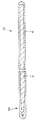
図1は、本発明のガイドワイヤの実施例を示す縦断面図である。同図に示すように、本発明のガイドワイヤ1Aは、芯材2と、該芯材2の全長に渡りその外周に巻回されたコイル3とで構成されている。このガイドワイヤ1Aは、全体として可撓性を有し、特に、ガイドワイヤとしての機能を十分に発揮し得るように適度な剛性および弾性を有している。
【0032】
また、芯材2の両端には、それぞれ、芯材2に対しコイル3が長手方向に移動しないように、止め部材4、5が設置されている。
【0033】
芯材2とコイル3とは、接触または密着していても、所定の間隙を介して離間していてもよいが、ガイドワイヤ1Aの可撓性(柔軟性)をより向上する上では、後者の方が好ましい。
【0034】
なお、コイル3を構成する線材の断面形状は、図示の例では、円形であるが、これに限らず、例えば、楕円形、半円形、半楕円形、三角形、矩形等の多角形、扁平形状(板状)等、いかなる形状のものでもよい。
【0035】
また、コイル3は、2層以上巻かれていてもよい。
【0036】
また、芯材2は、図示と異なり、多層構造のもの、中空状のもの、複数本を束ねたもの等であってもよい。
【0037】
このようなガイドワイヤ1Aでは、芯材2とコイル3のうちの少なくとも一方が、またはその一部が造影部を形成し、グラジエントエコー法により撮影したMRI画像中において実際の外径の1〜8倍のアーチファクトを生じるよう形成される。好ましくは、造影部が、40wt%以上のニッケルと、7wt%以下の鉄を含有する合金で形成される。特には、合金が、ニッケル45wt%以上、鉄2〜7wt%、クロム10〜25wt%、モリブデン10〜20wt%を含有し、必要によりさらにタングステン2〜5wt%を含有しても良い。
【0038】
また、このようなガイドワイヤ1Aでは、芯材2とコイル3のうちの少なくとも一方が、常温付近(10〜40℃程度)における外径方向の磁化率が、好ましくは0.5×10⁻⁴〜5.0×10⁻⁴、より好ましくは1.0×10⁻⁴〜3.0×10⁻⁴である金属材料で構成されている。
【0039】
このような磁気特性の金属材料(以下、「低磁化率金属材料」と言う)を用いることにより、前述したようなアーチファクトを生ぜしめることができる。従って、本実施例のガイドワイヤ1Aでは、そのほぼ全長に渡る部分が、前記造影部を構成することとなる。
【0040】
ここで、磁化率とは、次のように定義される。
【0041】
図6に示すMH磁化曲線(磁気ヒステリシス曲線)において、保磁力Hcと(単位体積[cm3 ]当たりの)残留磁化Mrの座標を持つ点Aと、原点0とを結ぶ直線の傾きを磁化率とする。
【0042】
この磁化率Xは、
【0043】
なお、芯材2またはコイル3の一方を前記低磁化率金属材料で構成しない場合、その構成材料としては、非磁性材料(金属材料、樹脂材料のいずれも可能)とすることができる。
【0044】
このようなガイドワイヤ1Aの外径は、特に限定されないが、通常、平均外径が0.25〜1.57mm程度であるのが好ましく、0.4〜0.97mm程度であるのがより好ましい。
【0045】
なお、例えば芯材2の先端部を、先端方向に向かってその外径が漸減するテーパ状とすることにより、ガイドワイヤ1Aの先端部10の剛性(曲げ剛性、捩り剛性等)を、先端方向に向かって漸減するような構成とすることもできる。このような構成とすることにより、ガイドワイヤ1Aのトルク伝達性、押し込み性(プッシャビリティ)、耐キンク性(耐折れ曲がり性)を十分に維持しつつ、先端部10の柔軟性を向上し、より高い安全性を確保することができる。
【0046】
図2は、本発明のガイドワイヤの他の実施例を示す縦断面図である。以下、図2に示すガイドワイヤ1Bについて、前記ガイドワイヤ1Aと相違する点を中心に説明し、同様の事項はその説明を省略する。
【0047】
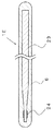
ガイドワイヤ1Bは、前記と同様の芯材2を有し、前記と同様のコイル3がガイドワイヤ1Bの先端部10にのみ設置されている。
【0048】
芯材2とコイル3のうちの少なくとも一方が、低磁化率金属材料で構成されている点は、前記と同様である。この場合、芯材2が低磁化率金属材料で構成されているガイドワイヤ1Bでは、そのほぼ全長に渡る部分が、前記造影部を構成することとなり、コイル3のみが低磁化率金属材料で構成されているガイドワイヤ1Bでは、先端部10のみが、前記造影部を構成することとなる。
【0049】
芯材2のコイル3より基端側の部分の外周には、被覆層6が被覆形成されている。この被覆層6を形成することにより、適度な柔軟性と強度を得ることができ、また、表面潤滑性ポリマーのコーティング層を設けることが可能となるという効果が得られる。
【0050】
この被覆層6は、有機高分子材料で構成されているのが好ましい。被覆層6を構成する有機高分子材料としては、例えば、ポリエチレン、ポリプロピレン、エチレン−酢酸ビニル共重合体などのポリオレフィン、ポリエチレンテレフタレート、ポリブチレンテレフタレート等のポリエステル、ポリ塩化ビニル、ポリ塩化ビニリデン、ポリスチレン、ポリアミド(例えばナイロン6、ナイロン66、ナイロン11、ナイロン12)、ポリイミド、ポリアミドイミド、ポリカーボネート、ポリ−(4−メチルペンテン−1)、アイオノマー、アクリル系樹脂、ポリメチルメタクリレート、アクリロニトリル−ブタジエン−スチレン共重合体(ABS樹脂)、アクリロニトリル−スチレン共重合体(AS樹脂)、ブタジエン−スチレン共重合体、ポリオキシメチレン、ポリビニルアルコール(PVA)、ポリエーテル、ポリエーテルケトン(PEK)、ポリエーテルエーテルケトン(PEEK)、ポリエーテルイミド、ポリアセタール(POM)、ポリフェニレンオキシド、変性ポリフェニレンオキシド、ポリサルフォン、ポリエーテルサルフォン、ポリフェニレンサルファイド、ポリアリレート、芳香族ポリエステル(液晶ポリマー)、ポリテトラフルオロエチレン、ポリフッ化ビニリデン、その他フッ素系樹脂、スチレン系、ポリオレフィン系、ポリ塩化ビニル系、ポリウレタン系、ポリエステル系、ポリアミド系、ポリブタジエン系、トランスポリイソプレン系、フッ素ゴム系、塩素化ポリエチレン系等の各種熱可塑性エラストマー、エポキシ樹脂、フェノール樹脂、ユリア樹脂、メラミン樹脂、不飽和ポリエステル、シリコーン樹脂、ポリウレタン等、またはこれらを主とする共重合体、ブレンド体、ポリマーアロイ等が挙げられ、これらのうちの1種または2種以上を組み合わせて(例えば2層以上の積層体として)用いることができる。また、被覆層6中には、X線透視下でガイドワイヤ1Bを使用した場合にもその位置を確認できるように、例えば硫酸バリウム、酸化ビスマス、タングステンのようなX線不透過材料が必要に応じて配合されていても良い。
【0051】
この被覆層6は、その構成材料の選定等により、芯材や後述するマーカーの保護、ガイドワイヤの滑り性の向上、表面潤滑性ポリマーのコーティング層の形成を可能とする等の効果をもたらす。
【0052】
被覆層6の厚さは、特に限定されないが、通常、0.05〜0.3mm程度であるのが好ましく、0.1〜0.2mm程度であるのがより好ましい。
【0053】
また、被覆層6の厚さは、被覆層6全体に渡って均一でも、部位により異なっていてもよい。例えば、先端方向に向かってその厚さが漸減または漸増する部分があってもよい。
【0054】
なお、被覆層6は、先端部10の領域、すなわちコイル3の外周を覆うように形成されていてもよい。また、被覆層6は、先端部10の領域のみに形成されていてもよい。
【0055】
以上のようなガイドワイヤ1A、1Bにおいて、コイル3に代えて、1つ以上のリング状の部材を用いることもできる。この場合、該リング状の部材の構成材料および特性は、コイル3で説明したものと同様のものとすることができる。
【0056】
図3は、本発明のガイドワイヤの他の実施例を示す縦断面図である。以下、図3に示すガイドワイヤ1Cについて、前記ガイドワイヤ1Bと相違する点を中心に説明し、同様の事項はその説明を省略する。
【0057】
ガイドワイヤ1Cは、芯材2を有し、そのほぼ全長に渡る外周に前記と同様の被覆層6が被覆形成されている。
【0058】
芯材2は、40wt%以上のニッケルと、7wt%以下の鉄を含有する合金で形成される。より好ましくは、さらに、クロムとモリブデンを含有する合金で形成される。時には、合金が、ニッケル45wt%以上、鉄2〜7wt%、クロム10〜25wt%、モリブデン10〜20wt%を含有し、必要によりさらにタングステン2〜5wt%を含有しても良い。あるいは、芯材2は、常温付近(10〜40℃程度)における外径方向の磁化率が、好ましくは0.5×10⁻⁴〜5.0×10⁻⁴、より好ましくは0.5×10⁻⁴〜3.0×10⁻⁴、さらにより好ましくは1.0×10⁻⁴〜2.8×10⁻⁴である金属材料で構成されている。
【0059】
このような特定の成分の合金、または特定の磁気特性の金属材料(低磁化率金属材料)を用いることにより、前述したようなアーチファクトを生ぜしめることができる。従って、本実施例のガイドワイヤ1Cでは、そのほぼ全長に渡る部分が、前記造影部を構成することとなる。
【0060】
なお、図示のように、芯材2の先端部は、先端方向に向かってその外径が漸減するテーパ状をなしているのが好ましい。これにより、ガイドワイヤ1Cの先端部10の剛性(曲げ剛性、捩り剛性等)を、先端方向に向かって漸減するような構成とすることもでき、ガイドワイヤ1Cのトルク伝達性、押し込み性(プッシャビリティ)、耐キンク性(耐折れ曲がり性)を十分に維持しつつ、先端部10の柔軟性を向上し、より高い安全性を確保することができる。
【0061】
図4は、本発明のガイドワイヤの他の実施例を示す縦断面図である。以下、図4に示すガイドワイヤ1Dについて、前記ガイドワイヤ1Cと相違する点を中心に説明し、同様の事項はその説明を省略する。
【0062】
ガイドワイヤ1Dは、芯材として、先端側の第1の芯材2aとそれより基端側の第2の芯材2bとを例えば溶接、ろう接、かしめ等により接合したものを用いた以外は、前記ガイドワイヤ1Cと同様である。
【0063】
この場合、第1の芯材2aと第2の芯材2bの構成材料の組成は異なっており、少なくとも第1の芯材2aが、前記特定の合金または前記低磁化率金属材料で構成されている。従って、本実施例のガイドワイヤ1Dでは、先端部10付近の部分が、前記造影部を構成することとなる。
【0064】
また、第1の芯材2aおよび第2の芯材2bのそれぞれが、上述の特定の合金または低磁化率金属材料で構成されていてもよい。尚、第1の芯材2aと第2の芯材2bとは、金属パイプを用いて接合することもできる。金属パイプは第1の芯材2aと同一の材料であることが好ましい。
【0065】
図5は、本発明のガイドワイヤの他の実施例を示す縦断面図である。以下、図5に示すガイドワイヤ1Eについて、前記ガイドワイヤ1Dと相違する点を中心に説明し、同様の事項はその説明を省略する。
【0066】
ガイドワイヤ1Eは、芯材23としてガイドワイヤとして最も好適な物性を有すると考えられる超弾性合金(NiTi合金)が用いられ、その先端は前記ガイドワイヤ1Eと同様にテーパ状に細径化されてなる。NiTi合金は、MRIモニター上に生じるアーチファクトが小さいため、特にその細径化された先端部で位置を視認することが困難であることは既に述べた。
【0067】
本実施例においては、芯材23の先端部にMRIマーカー24が設けられてる。MRIマーカー24は、40wt%以上のニッケルと、7wt%以下の鉄を含有する合金で形成される。より好ましくは、さらに、クロムとモリブデンを含有する合金で形成される。時には、合金が、ニッケル45wt%以上、鉄2〜7wt%、クロム10〜25wt%、モリブデン10〜20wt%を含有し、必要によりさらにタングステン2〜5wt%を含有しても良い。あるいは、MRIマーカー24は、常温付近(10〜40℃程度)における外径方向の磁化率が、好ましくは0.5×10⁻⁴〜5.0×10⁻⁴、より好ましくは0.5×10⁻⁴〜3.0×10⁻⁴、さらにより好ましくは1.0×10⁻⁴〜2.8×10⁻⁴である金属材料で構成されている。MRIマーカー24は、前記特定の合金を薄板上に加工したものを芯材23の先端部に接着またはかしめることによって構成されている。従って、本実施例のガイドワイヤ1Eでは、MRIマーカー24の部分が前記造影部を構成することとなる。
【0068】
MRIマーカー24の厚みは、20〜200μm程度が好ましい。更には、50〜100μm程度であるのがなお好ましい。また、MRIマーカー24のガイドワイヤ軸方向長さは、0.2〜10mm程度であるのが好ましく、更には0.5〜5mm程度がなお好ましい。
【0069】
ガイドワイヤ1Eは、更に全体を樹脂による被覆層6により被覆されているが、これについては、前記ガイドワイヤ1C、1Dと同様である。
【0070】
本発明のガイドワイヤの構成は、図示のガイドワイヤ1A〜1Eに限らず、好適なアーチファクトを生じる造影部を有するものであれば、いかなる構成のものであってもよい。
【0071】
【実施例】
以下、本発明の具体的実施例について詳細に説明する。
【0072】
(実施例1)
図1に示す構造のガイドワイヤを製造した。このガイドワイヤの各条件は、次の通りである。
【0073】
ガイドワイヤの全長:1500mm
ガイドワイヤの外径(平均):0.89mm
芯材の構成材料:低磁化率金属材料M1(組成は下記に示す)
芯材構成材料の磁化率:1.36×10⁻⁴
芯材の外径(平均):0.3mm
コイルの形態:1条1層密着巻き
コイルの構成材料:超弾性合金(Ni−Ti合金)
コイル線材の直径:0.15mm
(実施例2)
芯材の構成材料を下記低磁化率金属材料M2(磁化率:1.63×10⁻⁴)とした以外は、実施例1と同様のガイドワイヤを製造した。
【0074】
(実施例3)
芯材の構成材料を超弾性合金(Ni−Ti合金)、コイルの構成材料を低磁化率金属材料M1(磁化率:1.36×10⁻⁴)とした以外は、実施例1と同様のガイドワイヤを製造した。
【0075】
(実施例4)
芯材の構成材料を超弾性合金(Ni−Ti合金)、コイルの構成材料を低磁化率金属材料M2(磁化率:1.63×10⁻⁴)とした以外は、実施例1と同様のガイドワイヤを製造した。
【0076】
(実施例5)
図2に示す構造のガイドワイヤを製造した。このガイドワイヤの各条件は、次の通りである。
【0077】
ガイドワイヤの全長:1500mm
ガイドワイヤの外径(平均):0.89mm
芯材の構成材料:超弾性合金(Ni−Ti合金)
芯材の外径(平均):0.5mm
コイルの形態:1条1層密着巻き
コイルの形成領域:ガイドワイヤ先端から50mmまでの範囲
コイルの構成材料:低磁化率金属材料M1
コイル構成材料の磁化率:1.36×10⁻⁴
コイル線材の直径:0.15mm
被覆層組成:ポリウレタン
被覆層厚さ:0.2mm
(実施例6)
コイルの構成材料を低磁化率金属材料M2(磁化率:1.63×10⁻⁴)とした以外は、実施例5と同様のガイドワイヤを製造した。
【0078】
(実施例7)
芯材の構成材料を低磁化率金属材料M1(磁化率:1.36×10⁻⁴)とした以外は、実施例5と同様のガイドワイヤを製造した。
【0079】
(実施例8)
芯材の構成材料を低磁化率金属材料M2(磁化率:1.63×10⁻⁴)、コイルの構成材料を低磁化率金属材料M2(磁化率:1.63×10⁻⁴)とした以外は、実施例5と同様のガイドワイヤを製造した。
【0080】
(実施例9)
図3に示す構造のガイドワイヤを製造した。このガイドワイヤの各条件は、次の通りである。
【0081】
ガイドワイヤの全長:1500mm
ガイドワイヤの外径(平均):0.89mm
芯材の構成材料:低磁化率金属材料M1
芯材構成材料の磁化率:2.1×10⁻⁴
芯材の外径(平均):0.5mm(先端細径部:0.16mm)
被覆層組成:ポリウレタン
被覆層厚さ:0.2mm
(実施例10)
図4に示す構造のガイドワイヤを製造した。このガイドワイヤの各条件は、次の通りである。
【0082】
ガイドワイヤの全長:1500mm
ガイドワイヤの外径(平均):0.89mm
第1の芯材(先端側)の構成材料:低磁化率金属材料M1
第1の芯材構成材料の磁化率:2.1×10⁻⁴
第2の芯材(基端側)の構成材料:超弾性合金(Ni−Ti合金)
第1、第2の芯材の接合方法:溶接
芯材の外径(平均):0.5mm
被覆層組成:ポリウレタン
被覆層厚さ:0.2mm
(実施例11)
第2の芯材の構成材料を低磁化率金属材料M2(磁化率:2.38×10⁻⁴)とした以外は、実施例10と同様のガイドワイヤを製造した。
【0083】
(実施例12)
図5に示す構造のガイドワイヤを製造した。このガイドワイヤの各条件は、次の通りである。
【0084】
ガイドワイヤの全長:1800mm
ガイドワイヤの外径(平均):0.89mm
芯材の構成材料:超弾性合金(Ni−Ti合金)
芯材の外径(本体部):0.5mm
MRIマーカーの構成材料:低磁化率金属材料M1
MRIマーカーの寸法:幅2mm、厚さ80μm
MRIマーカーの形成方法:かしめ
被覆層組成:ポリウレタン
被覆層厚さ:0.2mm(本体部)
前記低磁化率金属材料M1、M2の組成は、次の通りである。
【0085】
[低磁化率金属材料M1]
Cr:21.5wt%
Mo:13.7wt%
W : 3.0wt%
Fe: 3.9wt%
Co: 0.7wt%
Mn: 0.17wt%
Si: 0.02wt%
Ni: 残部
[低磁化率金属材料M2]
Cr:14.7wt%
Mo:15.4wt%
W : 3.1wt%
Fe: 5.6wt%
Co: 1.0wt%
Mn: 0.6wt%
Si: 0.05wt%
Ni: 残部
(比較例1)
芯材の構成材料をステンレス鋼(SUS304、磁化率:15.23×10⁻⁴)とした以外は、実施例9と同様のガイドワイヤを製造した。
【0086】
(比較例2)
芯材の構成材料をNi−49wt%Ti合金とした以外は、実施例9と同様のガイドワイヤを製造した。
【0087】
<実験>
実施例1〜12、比較例1、2の各ガイドワイヤを水中に置いたものについて、MRI(GEメディカル社製)を用い、グラジエントエコー法により撮影し、そのMRI画像をモニターした。
【0088】
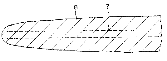
実施例1〜4、7〜9および11の各ガイドワイヤ(造影部がガイドワイヤのほぼ全長に渡って存在するもの)では、実際のガイドワイヤの輪郭7(図7中の点線)と、MRI画像に現れたガイドワイヤのアーチファクト8(図7中の実線)とは、図7に示すような形状(模式的に示す)となった。
【0089】
また、実施例5、6、10および12の各ガイドワイヤ(造影部がガイドワイヤの先端部に存在するもの)では、実際のガイドワイヤの輪郭7(図8中の点線)と、MRI画像に現れたガイドワイヤのアーチファクト8(図8中の実線)とは、図8に示すような形状(模式的に示す)となった。
【0090】
一方、比較例1のガイドワイヤでは、実際のガイドワイヤの輪郭7(図9中の点線)と、MRI画像に現れたガイドワイヤのアーチファクト8(図9中の実線)とは、図9に示すような形状(模式的に示す)となった。
【0091】
また、比較例2のガイドワイヤでは、実際のガイドワイヤの輪郭7(図10中の点線)と、MRI画像に現れたガイドワイヤのアーチファクト8(図10中の実線)とは、図10に示すような形状(模式的に示す)となった。なお、この場合、アーチファクトは、非常に不鮮明であり、視認しにくいものであった。
【0092】
MRI画像から、ガイドワイヤの造影部の実際の外径に対するアーチファクトの倍率(各部の平均値)を測定したところ、次のような結果となった。
【0093】
実施例1 :2.4倍
実施例2 :3.4倍
実施例3 :3.4倍
実施例4 :4.4倍
実施例5 :3.4倍
実施例6 :4.4倍
実施例7 :4.0倍
実施例8 :5.6倍
実施例9 :1.3倍
実施例10:1.3倍
実施例11:4.5倍
実施例12:2.6倍
比較例1 :25.6倍
比較例2 :0.5倍(先端部0.2倍)
以上の結果より、実施例1〜12の各ガイドワイヤでは、MRIのモニター画像において、ガイドワイヤの位置、特に先端部の位置や、ガイドワイヤの形状をより正確に把握することができる。
【0094】
これに対し、比較例1のガイドワイヤでは、ガイドワイヤの実際の外径より、アーチファクトが極端に大きく現れ、また、比較例2のガイドワイヤでは、ガイドワイヤの像が不鮮明であり、いずれの場合にも、ガイドワイヤの位置や形状を正確に把握することができない。
【0095】
【発明の効果】
以上述べたように、本発明のガイドワイヤによれば、ガイドワイヤの位置や形状をMRIによるモニター画像で適正に視認することができる。
【0096】
そのため、MRIによるモニター下で本発明のガイドワイヤを使用しつつ、検査、診断、治療等の医療行為を行う場合に、その医療行為を円滑、適正に行うことが可能となる。
【図面の簡単な説明】
【図1】本発明のガイドワイヤの実施例を示す縦断面図である。
【図2】本発明のガイドワイヤの他の実施例を示す縦断面図である。
【図3】本発明のガイドワイヤの他の実施例を示す縦断面図である。
【図4】本発明のガイドワイヤの他の実施例を示す縦断面図である。
【図5】本発明のガイドワイヤの他の実施例を示す縦断面図である。
【図6】MH磁化曲線を示す図である。
【図7】ガイドワイヤ(本発明)の輪郭と、MRI画像におけるガイドワイヤのアーチファクトの形状を示す模式図である。
【図8】ガイドワイヤ(本発明)の輪郭と、MRI画像におけるガイドワイヤのアーチファクトの形状を示す模式図である。
【図9】ガイドワイヤ(比較例)の輪郭と、MRI画像におけるガイドワイヤのアーチファクトの形状を示す模式図である。
【図10】ガイドワイヤ(比較例)の輪郭と、MRI画像におけるガイドワイヤのアーチファクトの形状を示す模式図である。
【符号の説明】
1 ガイドワイヤ
2 芯材
2a 第1の芯材
2b 第2の芯材
3 コイル
4、5 止め部材
6 被覆層
7 ガイドワイヤの輪郭
8 アーチファクト
10 先端部[0001]
BACKGROUND OF THE INVENTION
The present invention relates to a guide wire used for guiding various catheters, for example.
[0002]
[Prior art]
When inserting a catheter into a living body, a guide wire is inserted into the lumen of the catheter, and this is operated to guide the tip of the catheter so that blood vessel branching can be selected smoothly and reliably. ing.
[0003]
As a conventional guide wire, one made of stainless steel or a superelastic alloy (Ni-Ti alloy) is known.
[0004]
By the way, since insertion of the catheter in the living body is performed under X-ray fluoroscopy, X-ray contrast is imparted to the catheter.
[0005]
In recent years, examination and diagnosis by nuclear magnetic resonance apparatus: MRI (Magnetic Resonance Imaging) has been carried out. With the advancement of technology, a catheter and a guide wire are inserted into the body of a subject while monitoring this MRI image. In addition, it has become possible to perform medical practices such as examination, diagnosis and treatment.
[0006]
In this case, the conventional guide wire made of stainless steel is magnetized due to its material properties and work hardening that occurs during processing to wire, and therefore excessive when placed in a strong magnetic field of MRI. In response to this, a large artifact (non-existent image) appears on the MRI monitor image, and the guide wire is viewed more than 10 times the actual thickness. As a result, the position of the distal end portion of the guide wire in the living body cannot be accurately recognized, which may hinder the medical practice.
[0007]
Furthermore, due to the strong magnetizing action of MRI, the guide wire may generate heat, which may similarly interfere with the medical practice or adversely affect the living body.
[0008]
On the other hand, the conventional guide wire made of a superelastic alloy (Ni-Ti alloy) has an artifact generated on the MRI monitor image smaller than the actual thickness of the guide wire. It is difficult to confirm the position of the tip.
[0009]
[Problems to be solved by the invention]
An object of the present invention is to provide a guide wire that can be appropriately visually recognized on a monitor image by MRI.
[0010]
[Means for Solving the Problems]
Such an object is achieved by the following invention.
[0011]
(1) An MRI image photographed by a gradient echo method has a contrast part that generates an artifact that is 1 to 8 times the actual outer diameter, and the contrast part is nickel of 40 wt% or more, iron, chromium of 7 wt% or less And a guide wire comprising an alloy containing molybdenum.
[0012]
(2) The guide wire according to (1), wherein the alloy contains nickel 45 wt% or more, iron 2-7 wt%, chromium 10-25 wt%, and molybdenum 10-20 wt%.
[0013]
(3) The guide wire according to (1) or (2), wherein the guide wire includes a core member, and a distal end portion of the core member forms the contrast portion.
[0014]
(4) It has a core and a coil provided on the outer periphery of at least the tip of the core, and the portion where the coil exists in the longitudinal direction of the guide wire constitutes the contrast section (1) to ( The guide wire according to any one of 3).
[0015]
(5) The coil has a magnetic susceptibility of about 0.5 × 10 in the outer diameter direction near room temperature.-Four~ 5.0 × 10-FourThe guide wire according to (4), which is made of a metal material.
[0016]
(6) The guide wire according to (4) or (5), wherein one or more ring-shaped members are used instead of the coil.
[0017]
(7) The core material has a magnetic susceptibility of about 0.5 × 10 in the outer diameter direction near room temperature.-Four~ 5.0 × 10-Four(4) The guidewire according to any one of (4) to (6), which is made of a metal material.
[0018]
(8) The guide wire according to any one of (4) to (7), further including a coating layer that covers at least a part of the core material.
[0019]
(9) At least at the tip,Nickel 45wt% or more, iron 2-7wt%, chromium 10-25wt%, molybdenum 10-20wt%A guide wire having an MRI contrast portion made of an alloy containing the same.
[0020]
(10)The MRI contrast section has a magnetic susceptibility in the outer diameter direction of about 0.5 × 10 5 near room temperature. -Four ~ 5.0 × 10 -Four The guide wire according to (9).
[0021]
(11) At least the tip portion is made of an alloy containing nickel of 40 wt% or more and iron of 7 wt% or less, and the magnetic susceptibility in the outer diameter direction near room temperature is 0.5 × 10-Four~ 5.0 × 10-FourA guide wire comprising an MRI contrast unit.
[0022]
(12) It has a core material that exists over substantially the entire length of the guide wire, the MRI contrast portion is provided at the tip of the core material, and the core material is made of a superelastic alloy ( 9) The guide wire according to any one of (11).
[0023]
(13) Any one of (9) to (12), wherein the MRI contrast unit generates an artifact that is 1 to 8 times the outer diameter of an actual guide wire in an MRI image photographed by a gradient echo method. A guide wire according to crab.
[0024]
(14) A core material and provided at least at the tip of the core materialcoilAndAt least one of the core material and the coilIndicates that the magnetic susceptibility in the outer diameter direction near room temperature is 0.5 × 10-Four~ 5.0 × 10-FourA guide wire characterized by being.
[0025]
(15) The guide wire according to (14), wherein the core member is made of a nonmagnetic material.
(16)A ring-shaped member was used instead of the coil.(14) The guide wire according to (14).
[0026]
DETAILED DESCRIPTION OF THE INVENTION
Hereinafter, the guide wire of the present invention will be described in detail with reference to preferred embodiments shown in the accompanying drawings.
[0027]
The guide wire of the present invention can be used when performing medical procedures such as examination, diagnosis, and treatment under the operation of a nuclear magnetic resonance apparatus: MRI (Magnetic Resonance Imaging).
[0028]
The guide wire of the present invention is 1 to 8 times the outer diameter of the actual guide wire in the MRI image photographed by the gradient echo method, more preferably 1.5 to 7.5 times, still more preferably 2 It has a contrast section that produces ˜7 times artifact. If the artifact is too large, it is difficult to confirm the position of the guide wire in the body cavity, and if it is too small, the artifact may be difficult to see in an MRI image obtained by the spin echo method, which is another MRI imaging method.
[0029]
This contrast portion is preferably present at least at the tip of the guide wire.
[0030]
The specific structure of the guide wire of the present invention is not particularly limited as long as the guide wire has the above-described characteristics. However, an example of a preferable configuration will be described below with reference to FIGS. . 1 to 5, the right side is assumed to be the “base end” and the left side is assumed to be the “tip”.
[0031]
FIG. 1 is a longitudinal sectional view showing an embodiment of a guide wire according to the present invention. As shown in the figure, a guide wire 1A according to the present invention includes a
[0032]
[0033]
The
[0034]
In addition, although the cross-sectional shape of the wire constituting the coil 3 is a circle in the illustrated example, the shape is not limited to this. For example, an elliptical shape, a semicircular shape, a semi-elliptical shape, a polygonal shape such as a triangle or a rectangle, and a flat shape Any shape such as (plate) may be used.
[0035]
The coil 3 may be wound with two or more layers.
[0036]
Moreover, the
[0037]
In such a guide wire 1A, at least one of the
[0038]
In such a guide wire 1A, at least one of the
[0039]
By using a metal material having such a magnetic property (hereinafter referred to as “low magnetic susceptibility metal material”), the above-described artifact can be generated. Therefore, in the guide wire 1A of the present embodiment, a portion over almost the entire length forms the contrast portion.
[0040]
Here, the magnetic susceptibility is defined as follows.
[0041]
In the MH magnetization curve (magnetic hysteresis curve) shown in FIG. 6, the coercive force Hc and (unit volume [cm3 ], The slope of the straight line connecting the point A having the coordinates of the residual magnetization Mr and the origin 0 is defined as the magnetic susceptibility.
[0042]
This magnetic susceptibility X is
[0043]
When one of the
[0044]
The outer diameter of the guide wire 1A is not particularly limited, but usually, the average outer diameter is preferably about 0.25 to 1.57 mm, and more preferably about 0.4 to 0.97 mm. .
[0045]
Note that, for example, the distal end portion of the
[0046]
FIG. 2 is a longitudinal sectional view showing another embodiment of the guide wire of the present invention. Hereinafter, the guide wire 1B shown in FIG. 2 will be described with a focus on differences from the guide wire 1A, and the description of the same matters will be omitted.
[0047]
The guide wire 1B has the
[0048]
The point that at least one of the
[0049]
A coating layer 6 is formed on the outer periphery of a portion of the
[0050]
The covering layer 6 is preferably made of an organic polymer material. Examples of the organic polymer material constituting the coating layer 6 include polyolefins such as polyethylene, polypropylene, and ethylene-vinyl acetate copolymer, polyesters such as polyethylene terephthalate and polybutylene terephthalate, polyvinyl chloride, polyvinylidene chloride, polystyrene, Polyamide (for example, nylon 6, nylon 66, nylon 11, nylon 12), polyimide, polyamideimide, polycarbonate, poly- (4-methylpentene-1), ionomer, acrylic resin, polymethyl methacrylate, acrylonitrile-butadiene-styrene Polymer (ABS resin), acrylonitrile-styrene copolymer (AS resin), butadiene-styrene copolymer, polyoxymethylene, polyvinyl alcohol (PVA), polyether , Polyetherketone (PEK), polyetheretherketone (PEEK), polyetherimide, polyacetal (POM), polyphenylene oxide, modified polyphenylene oxide, polysulfone, polyethersulfone, polyphenylene sulfide, polyarylate, aromatic polyester (liquid crystal Polymer), polytetrafluoroethylene, polyvinylidene fluoride, other fluororesins, styrene, polyolefin, polyvinyl chloride, polyurethane, polyester, polyamide, polybutadiene, transpolyisoprene, fluororubber, chlorine Various types of thermoplastic elastomers such as fluorinated polyethylene, epoxy resins, phenol resins, urea resins, melamine resins, unsaturated polyesters, silicone resins, polyurethanes Etc., or a copolymer, blend to these primary polymer alloy and the like, can be used singly or in combination of two or more of these (e.g., a laminate of two or more layers). Further, in the covering layer 6, an X-ray opaque material such as barium sulfate, bismuth oxide, and tungsten is necessary so that the position can be confirmed even when the guide wire 1B is used under X-ray fluoroscopy. It may be blended accordingly.
[0051]
This coating layer 6 brings about effects such as protection of the core material and markers to be described later, improvement of the sliding property of the guide wire, and formation of a coating layer of the surface lubricity polymer by selecting the constituent material.
[0052]
Although the thickness of the coating layer 6 is not specifically limited, Usually, about 0.05-0.3 mm is preferable and it is more preferable that it is about 0.1-0.2 mm.
[0053]
Moreover, the thickness of the coating layer 6 may be uniform over the entire coating layer 6 or may be different depending on the part. For example, there may be a portion where the thickness gradually decreases or gradually increases in the distal direction.
[0054]
The covering layer 6 may be formed so as to cover the region of the
[0055]
In the guide wires 1A and 1B as described above, one or more ring-shaped members can be used instead of the coil 3. In this case, the constituent material and characteristics of the ring-shaped member can be the same as those described for the coil 3.
[0056]
FIG. 3 is a longitudinal sectional view showing another embodiment of the guide wire of the present invention. Hereinafter, the
[0057]
The
[0058]
The
[0059]
By using such an alloy of a specific component or a metal material (low magnetic susceptibility metal material) having a specific magnetic property, the above-described artifact can be generated. Therefore, in the guide wire 1C of the present embodiment, a portion over almost the entire length constitutes the contrast portion.
[0060]
As shown in the figure, it is preferable that the distal end portion of the
[0061]
FIG. 4 is a longitudinal sectional view showing another embodiment of the guide wire of the present invention. Hereinafter, the guide wire 1D shown in FIG. 4 will be described with a focus on differences from the guide wire 1C, and the description of the same matters will be omitted.
[0062]
The guide wire 1D, except that a core material in which the first core material 2a on the distal end side and the
[0063]
In this case, the composition of the constituent materials of the first core material 2a and the
[0064]
Moreover, each of the 1st core material 2a and the
[0065]
FIG. 5 is a longitudinal sectional view showing another embodiment of the guide wire of the present invention. Hereinafter, the guide wire 1E shown in FIG. 5 will be described with a focus on differences from the guide wire 1D, and the description of the same matters will be omitted.
[0066]
The guide wire 1E is made of a superelastic alloy (NiTi alloy) which is considered to have the most suitable physical properties as a guide wire as the
[0067]
In this embodiment, an
[0068]
The thickness of the
[0069]
The guide wire 1E is further covered with a coating layer 6 made of resin, which is the same as the guide wires 1C and 1D.
[0070]
The configuration of the guide wire of the present invention is not limited to the illustrated guide wires 1A to 1E, and any configuration may be used as long as it has a contrast section that generates a suitable artifact.
[0071]
【Example】
Hereinafter, specific examples of the present invention will be described in detail.
[0072]
Example 1
A guide wire having the structure shown in FIG. 1 was manufactured. Each condition of this guide wire is as follows.
[0073]
Guide wire length: 1500mm
Guide wire outer diameter (average): 0.89 mm
Core material: Low magnetic susceptibility metal material M1 (composition is shown below)
Magnetic susceptibility of core material: 1.36 × 10⁻⁴
Core outer diameter (average): 0.3 mm
Coil form: 1 single layer tightly wound
Coil constituent material: Superelastic alloy (Ni-Ti alloy)
Diameter of coil wire: 0.15mm
(Example 2)
The constituent material of the core material is the following low magnetic susceptibility metal material M2 (magnetic susceptibility: 1.63 × 10⁻⁴Except for the above, a guide wire similar to that of Example 1 was manufactured.
[0074]
(Example 3)
The core material is a superelastic alloy (Ni-Ti alloy), and the coil is a low magnetic susceptibility metal material M1 (magnetic susceptibility: 1.36 x 10).-4Except for the above, a guide wire similar to that of Example 1 was manufactured.
[0075]
Example 4
The core material is a superelastic alloy (Ni-Ti alloy), and the coil material is a low magnetic susceptibility metal material M2 (magnetic susceptibility: 1.63 × 10⁻⁴Except for the above, a guide wire similar to that of Example 1 was manufactured.
[0076]
(Example 5)
A guide wire having the structure shown in FIG. 2 was manufactured. Each condition of this guide wire is as follows.
[0077]
Guide wire length: 1500mm
Guide wire outer diameter (average): 0.89 mm
Core material: Superelastic alloy (Ni-Ti alloy)
Core outer diameter (average): 0.5 mm
Coil form: 1 single layer tightly wound
Coil formation area: Range from the tip of the guide wire to 50 mm
Coil material: Low magnetic susceptibility metal material M1
Magnetic susceptibility of coil constituent material: 1.36 × 10⁻⁴
Diameter of coil wire: 0.15mm
Coating layer composition: Polyurethane
Coating layer thickness: 0.2mm
(Example 6)
The constituent material of the coil is a low magnetic susceptibility metal material M2 (magnetic susceptibility: 1.63 × 10⁻⁴Except for the above, a guide wire similar to that of Example 5 was manufactured.
[0078]
(Example 7)
The constituent material of the core material is a low magnetic susceptibility metal material M1 (magnetic susceptibility: 1.36 × 10⁻⁴Except for the above, a guide wire similar to that of Example 5 was manufactured.
[0079]
(Example 8)
The constituent material of the core material is a low magnetic susceptibility metal material M2 (magnetic susceptibility: 1.63 × 10⁻⁴), The constituent material of the coil is a low magnetic susceptibility metal material M2 (magnetic susceptibility: 1.63 × 10⁻⁴Except for the above, a guide wire similar to that of Example 5 was manufactured.
[0080]
Example 9
A guide wire having the structure shown in FIG. 3 was manufactured. Each condition of this guide wire is as follows.
[0081]
Guide wire length: 1500mm
Guide wire outer diameter (average): 0.89 mm
Core material: Low magnetic susceptibility metal material M1
Magnetic susceptibility of core material: 2.1 × 10⁻⁴
Outer diameter of core material (average): 0.5 mm (fine tip portion: 0.16 mm)
Coating layer composition: Polyurethane
Coating layer thickness: 0.2mm
(Example 10)
A guide wire having the structure shown in FIG. 4 was manufactured. Each condition of this guide wire is as follows.
[0082]
Guide wire length: 1500mm
Guide wire outer diameter (average): 0.89 mm
Constituent material of first core material (tip side): low magnetic susceptibility metal material M1
Magnetic susceptibility of first core material: 2.1 × 10⁻⁴
Constituent material of second core material (base end side): Superelastic alloy (Ni-Ti alloy)
First and second core material joining method: welding
Core outer diameter (average): 0.5 mm
Coating layer composition: Polyurethane
Coating layer thickness: 0.2mm
(Example 11)
The constituent material of the second core material is a low magnetic susceptibility metal material M2 (magnetic susceptibility: 2.38 × 10⁻⁴Except for the above, a guide wire similar to that of Example 10 was manufactured.
[0083]
(Example 12)
A guide wire having the structure shown in FIG. 5 was manufactured. Each condition of this guide wire is as follows.
[0084]
Total length of guide wire: 1800mm
Guide wire outer diameter (average): 0.89 mm
Core material: Superelastic alloy (Ni-Ti alloy)
Core outer diameter (main part): 0.5 mm
Material of MRI marker: Low magnetic susceptibility metal material M1
Dimensions of MRI marker: width 2mm, thickness 80μm
MRI marker formation method: caulking
Coating layer composition: Polyurethane
Covering layer thickness: 0.2mm (main part)
The composition of the low magnetic susceptibility metal materials M1 and M2 is as follows.
[0085]
[Low magnetic susceptibility metal material M1]
Cr: 21.5 wt%
Mo: 13.7 wt%
W: 3.0 wt%
Fe: 3.9 wt%
Co: 0.7 wt%
Mn: 0.17 wt%
Si: 0.02 wt%
Ni: remaining
[Low magnetic susceptibility metal material M2]
Cr: 14.7 wt%
Mo: 15.4 wt%
W: 3.1 wt%
Fe: 5.6 wt%
Co: 1.0 wt%
Mn: 0.6 wt%
Si: 0.05 wt%
Ni: remaining
(Comparative Example 1)
The core material is stainless steel (SUS304, magnetic susceptibility: 15.23 × 10⁻⁴Except for the above, a guide wire similar to that of Example 9 was manufactured.
[0086]
(Comparative Example 2)
A guide wire similar to that of Example 9 was produced except that the constituent material of the core material was Ni-49 wt% Ti alloy.
[0087]
<Experiment>
About what put each guide wire of Examples 1-12 and Comparative Examples 1 and 2 in water, it image | photographed by the gradient echo method using MRI (made by GE Medical), and monitored the MRI image.
[0088]
In each of the guide wires of Examples 1 to 4, 7 to 9 and 11 (the contrast portion is present over almost the entire length of the guide wire), the actual guide wire outline 7 (dotted line in FIG. 7), MRI The guide wire artifact 8 (solid line in FIG. 7) appearing in the image has a shape (schematically shown) as shown in FIG.
[0089]
Further, in each of the guide wires of Examples 5, 6, 10 and 12 (the contrast portion is present at the distal end portion of the guide wire), an actual guide wire outline 7 (dotted line in FIG. 8) and an MRI image are displayed. The appearing guide wire artifact 8 (solid line in FIG. 8) has a shape (schematically shown) as shown in FIG.
[0090]
On the other hand, in the guide wire of Comparative Example 1, the actual guide wire outline 7 (dotted line in FIG. 9) and the guide wire artifact 8 (solid line in FIG. 9) appearing in the MRI image are shown in FIG. It became such a shape (schematically shown).
[0091]
In the guide wire of Comparative Example 2, the actual guide wire contour 7 (dotted line in FIG. 10) and the guide wire artifact 8 (solid line in FIG. 10) appearing in the MRI image are shown in FIG. It became such a shape (schematically shown). In this case, the artifact was very unclear and difficult to visually recognize.
[0092]
When the magnification of the artifact (average value of each part) with respect to the actual outer diameter of the contrasted part of the guide wire was measured from the MRI image, the following results were obtained.
[0093]
Example 1: 2.4 times
Example 2: 3.4 times
Example 3: 3.4 times
Example 4: 4.4 times
Example 5: 3.4 times
Example 6: 4.4 times
Example 7: 4.0 times
Example 8: 5.6 times
Example 9: 1.3 times
Example 10: 1.3 times
Example 11: 4.5 times
Example 12: 2.6 times
Comparative Example 1: 25.6 times
Comparative Example 2: 0.5 times (tip portion 0.2 times)
From the above results, in each of the guide wires of Examples 1 to 12, the position of the guide wire, particularly the position of the distal end portion and the shape of the guide wire can be grasped more accurately in the MRI monitor image.
[0094]
On the other hand, in the guide wire of Comparative Example 1, artifacts appear to be extremely larger than the actual outer diameter of the guide wire, and in the guide wire of Comparative Example 2, the image of the guide wire is unclear. In addition, the position and shape of the guide wire cannot be accurately grasped.
[0095]
【The invention's effect】
As described above, according to the guide wire of the present invention, the position and shape of the guide wire can be properly visually confirmed on the monitor image by MRI.
[0096]
Therefore, when a medical action such as examination, diagnosis, treatment or the like is performed while using the guide wire of the present invention under the MRI monitor, the medical action can be performed smoothly and appropriately.
[Brief description of the drawings]
FIG. 1 is a longitudinal sectional view showing an embodiment of a guide wire according to the present invention.
FIG. 2 is a longitudinal sectional view showing another embodiment of the guide wire according to the present invention.
FIG. 3 is a longitudinal sectional view showing another embodiment of the guide wire of the present invention.
FIG. 4 is a longitudinal sectional view showing another embodiment of the guide wire according to the present invention.
FIG. 5 is a longitudinal sectional view showing another embodiment of the guide wire of the present invention.
FIG. 6 is a diagram showing an MH magnetization curve.
FIG. 7 is a schematic diagram showing the outline of a guide wire (present invention) and the shape of the guide wire artifact in the MRI image.
FIG. 8 is a schematic diagram showing the outline of a guide wire (invention) and the shape of the guide wire artifact in the MRI image.
FIG. 9 is a schematic diagram showing the outline of a guide wire (comparative example) and the shape of the guide wire artifact in the MRI image.
FIG. 10 is a schematic diagram showing the outline of a guide wire (comparative example) and the shape of a guide wire artifact in an MRI image.
[Explanation of symbols]
1 Guide wire
2 Core material
2a First core material
2b Second core material
3 coils
4, 5 Stopping member
6 Coating layer
7 Guide wire outline
8 Artifact
10 Tip
Claims (16)
Priority Applications (1)
| Application Number | Priority Date | Filing Date | Title |
|---|---|---|---|
| JP08224798A JP3619366B2 (en) | 1997-03-31 | 1998-03-27 | Guide wire |
Applications Claiming Priority (3)
| Application Number | Priority Date | Filing Date | Title |
|---|---|---|---|
| JP9650297 | 1997-03-31 | ||
| JP9-96502 | 1997-03-31 | ||
| JP08224798A JP3619366B2 (en) | 1997-03-31 | 1998-03-27 | Guide wire |
Publications (2)
| Publication Number | Publication Date |
|---|---|
| JPH10328157A JPH10328157A (en) | 1998-12-15 |
| JP3619366B2 true JP3619366B2 (en) | 2005-02-09 |
Family
ID=26423263
Family Applications (1)
| Application Number | Title | Priority Date | Filing Date |
|---|---|---|---|
| JP08224798A Expired - Fee Related JP3619366B2 (en) | 1997-03-31 | 1998-03-27 | Guide wire |
Country Status (1)
| Country | Link |
|---|---|
| JP (1) | JP3619366B2 (en) |
Families Citing this family (7)
| Publication number | Priority date | Publication date | Assignee | Title |
|---|---|---|---|---|
| JP4138583B2 (en) | 2002-08-08 | 2008-08-27 | テルモ株式会社 | Guide wire |
| JP4783345B2 (en) * | 2002-08-08 | 2011-09-28 | テルモ株式会社 | Guide wire |
| JP5135452B2 (en) * | 2002-08-08 | 2013-02-06 | テルモ株式会社 | Guide wire |
| JP4203358B2 (en) | 2002-08-08 | 2008-12-24 | テルモ株式会社 | Guide wire |
| JP5089517B2 (en) * | 2002-08-08 | 2012-12-05 | テルモ株式会社 | Guide wire |
| JP4138582B2 (en) | 2002-08-23 | 2008-08-27 | テルモ株式会社 | Guide wire |
| JP7197579B2 (en) * | 2017-11-13 | 2022-12-27 | バイオコンパティブルズ ユーケー リミテッド | Cryoprobe for magnetic resonance imaging |
-
1998
- 1998-03-27 JP JP08224798A patent/JP3619366B2/en not_active Expired - Fee Related
Also Published As
| Publication number | Publication date |
|---|---|
| JPH10328157A (en) | 1998-12-15 |
Similar Documents
| Publication | Publication Date | Title |
|---|---|---|
| US6019737A (en) | Guide wire | |
| JPH10290839A (en) | Guide wire | |
| US7547288B2 (en) | Guide wire | |
| US5728079A (en) | Catheter which is visible under MRI | |
| US20070016131A1 (en) | Flexible magnets for navigable medical devices | |
| JP4489427B2 (en) | Microcatheter with improved distal tip and transition | |
| US20090182246A1 (en) | Guide wire | |
| US7641621B2 (en) | Elongated intra-lumenal medical device | |
| US8414634B2 (en) | Elongate medical device | |
| US9295813B2 (en) | Guidewire | |
| JP2007236472A (en) | Catheter | |
| JP2008229160A (en) | Catheter | |
| EP1379311A1 (en) | Microcatheter with improved distal tip and transitions | |
| JP2004517694A (en) | Non-metallic guidewire | |
| JP3619366B2 (en) | Guide wire | |
| JPH08173545A (en) | Catheter that can be seen by magnetic resonance device | |
| JP3607456B2 (en) | Guide wire | |
| US11890428B2 (en) | Catheter | |
| JP3962724B2 (en) | Guide wire | |
| JP3786312B2 (en) | catheter | |
| JP5430065B2 (en) | Guide wire | |
| JP5354916B2 (en) | Transendoscopic guidewire | |
| US9014816B2 (en) | Medical lead with filler layer | |
| JP5979879B2 (en) | Guide wire | |
| WO2023150775A1 (en) | Medical devices for interventional mri |
Legal Events
| Date | Code | Title | Description |
|---|---|---|---|
| A977 | Report on retrieval |
Free format text: JAPANESE INTERMEDIATE CODE: A971007 Effective date: 20040122 |
|
| A131 | Notification of reasons for refusal |
Free format text: JAPANESE INTERMEDIATE CODE: A131 Effective date: 20040203 |
|
| A521 | Written amendment |
Free format text: JAPANESE INTERMEDIATE CODE: A523 Effective date: 20040401 |
|
| A131 | Notification of reasons for refusal |
Free format text: JAPANESE INTERMEDIATE CODE: A131 Effective date: 20040727 |
|
| A521 | Written amendment |
Free format text: JAPANESE INTERMEDIATE CODE: A523 Effective date: 20040915 |
|
| TRDD | Decision of grant or rejection written | ||
| A01 | Written decision to grant a patent or to grant a registration (utility model) |
Free format text: JAPANESE INTERMEDIATE CODE: A01 Effective date: 20041019 |
|
| A61 | First payment of annual fees (during grant procedure) |
Free format text: JAPANESE INTERMEDIATE CODE: A61 Effective date: 20041112 |
|
| R150 | Certificate of patent or registration of utility model |
Free format text: JAPANESE INTERMEDIATE CODE: R150 |
|
| FPAY | Renewal fee payment (event date is renewal date of database) |
Free format text: PAYMENT UNTIL: 20081119 Year of fee payment: 4 |
|
| FPAY | Renewal fee payment (event date is renewal date of database) |
Free format text: PAYMENT UNTIL: 20081119 Year of fee payment: 4 |
|
| FPAY | Renewal fee payment (event date is renewal date of database) |
Free format text: PAYMENT UNTIL: 20091119 Year of fee payment: 5 |
|
| FPAY | Renewal fee payment (event date is renewal date of database) |
Free format text: PAYMENT UNTIL: 20091119 Year of fee payment: 5 |
|
| FPAY | Renewal fee payment (event date is renewal date of database) |
Free format text: PAYMENT UNTIL: 20101119 Year of fee payment: 6 |
|
| FPAY | Renewal fee payment (event date is renewal date of database) |
Free format text: PAYMENT UNTIL: 20111119 Year of fee payment: 7 |
|
| FPAY | Renewal fee payment (event date is renewal date of database) |
Free format text: PAYMENT UNTIL: 20121119 Year of fee payment: 8 |
|
| FPAY | Renewal fee payment (event date is renewal date of database) |
Free format text: PAYMENT UNTIL: 20121119 Year of fee payment: 8 |
|
| FPAY | Renewal fee payment (event date is renewal date of database) |
Free format text: PAYMENT UNTIL: 20131119 Year of fee payment: 9 |
|
| LAPS | Cancellation because of no payment of annual fees |