CN107810028B - Three-dimensional right auricle bending catheter - Google Patents
Three-dimensional right auricle bending catheter Download PDFInfo
- Publication number
- CN107810028B CN107810028B CN201680027776.XA CN201680027776A CN107810028B CN 107810028 B CN107810028 B CN 107810028B CN 201680027776 A CN201680027776 A CN 201680027776A CN 107810028 B CN107810028 B CN 107810028B
- Authority
- CN
- China
- Prior art keywords
- catheter
- atrial appendage
- wall
- distal end
- raa
- Prior art date
- Legal status (The legal status is an assumption and is not a legal conclusion. Google has not performed a legal analysis and makes no representation as to the accuracy of the status listed.)
- Active
Links
Images


Classifications
-
- A—HUMAN NECESSITIES
- A61—MEDICAL OR VETERINARY SCIENCE; HYGIENE
- A61M—DEVICES FOR INTRODUCING MEDIA INTO, OR ONTO, THE BODY; DEVICES FOR TRANSDUCING BODY MEDIA OR FOR TAKING MEDIA FROM THE BODY; DEVICES FOR PRODUCING OR ENDING SLEEP OR STUPOR
- A61M25/00—Catheters; Hollow probes
- A61M25/0021—Catheters; Hollow probes characterised by the form of the tubing
- A61M25/0041—Catheters; Hollow probes characterised by the form of the tubing pre-formed, e.g. specially adapted to fit with the anatomy of body channels
-
- A—HUMAN NECESSITIES
- A61—MEDICAL OR VETERINARY SCIENCE; HYGIENE
- A61B—DIAGNOSIS; SURGERY; IDENTIFICATION
- A61B17/00—Surgical instruments, devices or methods, e.g. tourniquets
- A61B17/00234—Surgical instruments, devices or methods, e.g. tourniquets for minimally invasive surgery
-
- A—HUMAN NECESSITIES
- A61—MEDICAL OR VETERINARY SCIENCE; HYGIENE
- A61B—DIAGNOSIS; SURGERY; IDENTIFICATION
- A61B17/00—Surgical instruments, devices or methods, e.g. tourniquets
- A61B17/34—Trocars; Puncturing needles
- A61B17/3415—Trocars; Puncturing needles for introducing tubes or catheters, e.g. gastrostomy tubes, drain catheters
-
- A—HUMAN NECESSITIES
- A61—MEDICAL OR VETERINARY SCIENCE; HYGIENE
- A61B—DIAGNOSIS; SURGERY; IDENTIFICATION
- A61B18/00—Surgical instruments, devices or methods for transferring non-mechanical forms of energy to or from the body
- A61B18/04—Surgical instruments, devices or methods for transferring non-mechanical forms of energy to or from the body by heating
- A61B18/12—Surgical instruments, devices or methods for transferring non-mechanical forms of energy to or from the body by heating by passing a current through the tissue to be heated, e.g. high-frequency current
- A61B18/14—Probes or electrodes therefor
- A61B18/1492—Probes or electrodes therefor having a flexible, catheter-like structure, e.g. for heart ablation
-
- A—HUMAN NECESSITIES
- A61—MEDICAL OR VETERINARY SCIENCE; HYGIENE
- A61B—DIAGNOSIS; SURGERY; IDENTIFICATION
- A61B17/00—Surgical instruments, devices or methods, e.g. tourniquets
- A61B17/12—Surgical instruments, devices or methods, e.g. tourniquets for ligaturing or otherwise compressing tubular parts of the body, e.g. blood vessels, umbilical cord
- A61B17/12022—Occluding by internal devices, e.g. balloons or releasable wires
- A61B17/12099—Occluding by internal devices, e.g. balloons or releasable wires characterised by the location of the occluder
- A61B17/12122—Occluding by internal devices, e.g. balloons or releasable wires characterised by the location of the occluder within the heart
-
- A—HUMAN NECESSITIES
- A61—MEDICAL OR VETERINARY SCIENCE; HYGIENE
- A61B—DIAGNOSIS; SURGERY; IDENTIFICATION
- A61B17/00—Surgical instruments, devices or methods, e.g. tourniquets
- A61B17/00234—Surgical instruments, devices or methods, e.g. tourniquets for minimally invasive surgery
- A61B2017/00238—Type of minimally invasive operation
- A61B2017/00243—Type of minimally invasive operation cardiac
-
- A—HUMAN NECESSITIES
- A61—MEDICAL OR VETERINARY SCIENCE; HYGIENE
- A61B—DIAGNOSIS; SURGERY; IDENTIFICATION
- A61B17/00—Surgical instruments, devices or methods, e.g. tourniquets
- A61B17/00234—Surgical instruments, devices or methods, e.g. tourniquets for minimally invasive surgery
- A61B2017/00292—Surgical instruments, devices or methods, e.g. tourniquets for minimally invasive surgery mounted on or guided by flexible, e.g. catheter-like, means
- A61B2017/003—Steerable
- A61B2017/00318—Steering mechanisms
- A61B2017/00331—Steering mechanisms with preformed bends
-
- A—HUMAN NECESSITIES
- A61—MEDICAL OR VETERINARY SCIENCE; HYGIENE
- A61B—DIAGNOSIS; SURGERY; IDENTIFICATION
- A61B17/00—Surgical instruments, devices or methods, e.g. tourniquets
- A61B17/22—Implements for squeezing-off ulcers or the like on the inside of inner organs of the body; Implements for scraping-out cavities of body organs, e.g. bones; Calculus removers; Calculus smashing apparatus; Apparatus for removing obstructions in blood vessels, not otherwise provided for
- A61B2017/22051—Implements for squeezing-off ulcers or the like on the inside of inner organs of the body; Implements for scraping-out cavities of body organs, e.g. bones; Calculus removers; Calculus smashing apparatus; Apparatus for removing obstructions in blood vessels, not otherwise provided for with an inflatable part, e.g. balloon, for positioning, blocking, or immobilisation
- A61B2017/22065—Functions of balloons
- A61B2017/22069—Immobilising; Stabilising
-
- A—HUMAN NECESSITIES
- A61—MEDICAL OR VETERINARY SCIENCE; HYGIENE
- A61M—DEVICES FOR INTRODUCING MEDIA INTO, OR ONTO, THE BODY; DEVICES FOR TRANSDUCING BODY MEDIA OR FOR TAKING MEDIA FROM THE BODY; DEVICES FOR PRODUCING OR ENDING SLEEP OR STUPOR
- A61M25/00—Catheters; Hollow probes
- A61M25/0067—Catheters; Hollow probes characterised by the distal end, e.g. tips
- A61M25/0082—Catheter tip comprising a tool
-
- A—HUMAN NECESSITIES
- A61—MEDICAL OR VETERINARY SCIENCE; HYGIENE
- A61M—DEVICES FOR INTRODUCING MEDIA INTO, OR ONTO, THE BODY; DEVICES FOR TRANSDUCING BODY MEDIA OR FOR TAKING MEDIA FROM THE BODY; DEVICES FOR PRODUCING OR ENDING SLEEP OR STUPOR
- A61M25/00—Catheters; Hollow probes
- A61M25/01—Introducing, guiding, advancing, emplacing or holding catheters
- A61M25/09—Guide wires
- A61M25/09041—Mechanisms for insertion of guide wires
-
- A—HUMAN NECESSITIES
- A61—MEDICAL OR VETERINARY SCIENCE; HYGIENE
- A61M—DEVICES FOR INTRODUCING MEDIA INTO, OR ONTO, THE BODY; DEVICES FOR TRANSDUCING BODY MEDIA OR FOR TAKING MEDIA FROM THE BODY; DEVICES FOR PRODUCING OR ENDING SLEEP OR STUPOR
- A61M25/00—Catheters; Hollow probes
- A61M25/10—Balloon catheters
Abstract
Disclosed herein are delivery catheters having a three-dimensional curve that facilitate access to the RAA from the inferior vena cava, position the distal end of the catheter to a puncture location within the RAA that is substantially parallel to the plane of the pericardial cavity, orient the puncture device in a direction that avoids the right coronary artery, aorta, pulmonary artery, and other structures, thereby preventing "bystander" injury to these structures, and provide sufficient rigidity to penetrate the wall of the RAA into the pericardial cavity.
Description
Cross Reference to Related Applications
This application claims the benefit of U.S. provisional patent application No. 62/162,453 filed on 5/15/2015, the disclosure of which is hereby incorporated by reference in its entirety.
Technical Field
The present disclosure relates to catheters and other devices for accessing the pericardial space through the right atrium and right atrial appendage.
Background
Some procedures require access to the pericardial space, such as left atrial appendage ligation, annuloplasty, or epicardial ligation for heart rate disorders. One way to reach the pericardial space is by advancing a transvascular catheter through the right atrium and into the right atrial appendage, and passing the catheter through a puncture in the right atrial appendage into the pericardial space. However, these procedures may present risks of myocardial or coronary laceration, among other risks.
Disclosure of Invention
Disclosed herein are curved catheters that are shaped and configured to be more safely guided through the Right Atrial Appendage (RAA) and more effectively exit through the left superior sulcus wall of the RAA into the pericardial space in a desired orientation, which reduces the risk of injury to "bystander" tissue and increases the success rate of the procedure required to reach the pericardial space.
The disclosed catheter can include a proximal portion, a transition portion extending distally from the proximal portion, a distal portion extending distally from the transition portion, and a distal end, wherein the transition portion and/or the distal portion are adapted to extend from the proximal portion in a clockwise helical bend when the catheter is positioned within a patient. When inserted into the patient, the proximal portion is located within the inferior vena cava, the transition portion extends across the vena cava-to-atrium interface and curves right, forward, and upward such that the catheter abuts a right sidewall of the right atrium, and the distal portion curves left, forward, and upward from the transition portion across the right atrium such that the catheter abuts an anterior wall of the right atrium adjacent to the RAA, and the distal portion continues to curve left, rearward, and upward from the anterior wall of the right atrium along the anterior superior wall of the RAA such that the distal end of the catheter contacts a cephalad wall of the RAA. The catheter is configured to guide a coaxial puncturing device to extend from the distal end of the catheter, and to pierce the left superior sulcus wall of the RAA safely cephalad into the pericardial space and away from critical structures, such as the coronary arteries. The bending of the catheter orients the distal end of the catheter pointing generally to the left and parallel to the pericardium so that the puncturing device passes through the cephalad wall of the RAA and into the pericardial space without damaging the pericardium, and in a spaced apart position from the right coronary, pulmonary, and aorta, thereby minimizing the risk of damaging such "bystander" structures. The catheter can be configured to be delivered and/or used with an inflatable balloon catheter that is inflated within the RAA to separate or flatten trabecular formations within the RAA, thereby facilitating advancement of the distal end of the catheter relative to the left sulcus wall of the RAA.
The above described and other features and advantages of the disclosed technology will become more apparent from the following detailed description of several embodiments, which proceeds with reference to the accompanying drawings.
Drawings
Fig. 1 shows a model representing the internal volume of the heart as seen from the right side. The right atrial appendage is anterior.
Fig. 2 shows a model representing the internal volume of the venous structure of the heart only.
Fig. 3 shows an illustrative curved catheter extending through the inferior vena cava, through the right atrium, and into the right atrial appendage against the cephalad left sulcus wall.
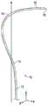
Figure 4 shows the curved conduit of figure 3 in isolation.
Fig. 5A-5H show various side views of the curved catheter of fig. 4 as the catheter is rotated about a vertical axis.
Fig. 6 and 7 show another illustrative curved catheter.
Fig. 8A-8D are X-ray images showing the use of a curved catheter to engage the right atrial appendage from the inferior vena cava (fig. 8A), and then to align and engage the outer or anterior wall of the right atrial appendage with the apex abutting the cephalic left sulcus wall of the right atrial appendage (fig. 8B). In fig. 8C, the guide wire exits the catheter, traversing the wall of the right atrial appendage and entering the pericardial space, and in fig. 8D, the microcatheter is passed over the guide wire from the right atrium into the pericardial space by bending the catheter.
Fig. 9A-9D are X-ray images showing another illustrative procedure using a curved catheter to reach the pericardial space through the right atrial appendage.
Fig. 10 is a contrast agent peripheral cardiogram showing two alternative exit trajectories from the right atrial appendage.
Detailed Description
The catheters, systems, and methods described herein can be used to perform various intrapericardial procedures, such as left atrial appendage transfixion, epicardial ligation for heart rhythm disorders, and tricuspid valvuloplasty. More information about these procedures and related systems and devices can be found in the following documents: international publication No. WO 2014/015842Al entitled "DEVICES AND METHODS FOR measuring FUNCTIONAL ternary VALVE Regurgitation" published on 2.10.2014; international publication No. WO 2014/200764Al entitled "ENCIRCLING IMPLANT DELIVERY SYSTEMS AND METHODS" published on 18/12/2014; and international publication No. WO 2015/061775 Al entitled "ATRIAL APPENDAGE restriction" published on 30/4/2015; the disclosure of which is hereby incorporated by reference in its entirety.
As used herein, the direction "right" relates to the right side of the patient, and the term "left" relates to the left side of the patient. Similarly, the terms "anterior" and "posterior" refer to the anterior and posterior sides of the patient. Terms such as "upper" and "top" relate to the superior direction of the patient, and terms such as "lower" and "bottom" relate to the inferior direction of the patient. As used herein, "distal" and "proximal" refer to the proximal and distal ends of a catheter or other transvascular device, the proximal direction being toward the point of insertion into the patient and the distal direction being toward the free end of the device.
Fig. 1 and 2 show a model of the internal volume of the heart, and in particular the geometry and orientation of the Right Atrium (RA) and right auricle (RAA). In fig. 1, the entire interior of the heart is shown from the right, while fig. 2 shows only the hypoxic blood zone of the heart (e.g., the right side of the heart, the venous lumen, the pulmonary artery, etc.). As shown, the RA and RAA include irregular inner wall surfaces forming numerous small folds, flaps, and slits that may impede delivery of the catheter device.
The disclosed delivery catheter has a three-dimensional bend that facilitates access to the RAA from the femoral vein through the inferior vena cava, positions the distal end of the catheter substantially parallel to the plane of the pericardial cavity at the puncture location within the RAA, orients the puncture device in an orientation that avoids the right coronary artery, aorta, pulmonary artery, and left atrial appendage to prevent injury to these structures by a "bystander", and provides sufficient rigidity to penetrate the cephalad wall of the RAA into the pericardial cavity.
Fig. 3 shows an illustrative curved catheter 10 extending through the IVC, through the RA, and into the RAA. As shown in fig. 4, the disclosed catheter comprises three portions. The first, proximal portion 12 is generally straight or slightly curved and can project generally perpendicularly through the IVC. The second, transition section 13 can be positioned near the vena cava-atrial interface to curve toward the patient's right and anterior sides. As shown in fig. 4, the catheter 10 is passed after the vertical z-axis at the transition portion 13, then bent around the z-axis at the third, distal portion 14 and passed in front of it, the third, distal portion 14 being bent more sharply towards the patient's left side towards the distal end 18 of the catheter when the catheter is positioned for use. The distal portion 10 can also include a generally straight portion 16 at the distal end that can extend generally transversely within the patient.
The transition section 13 and the distal section 14 spiral clockwise from the proximal section 12 towards the straight distal section 16. The helical or spiral bend is shown in fig. 4 with reference to the straight vertical z-axis. The terms "helical" and "spiral" are used interchangeably herein and are defined broadly herein to mean any three-dimensional bend that bends about a central axis, as the bend also extends in the direction of the central axis, and these terms do not require that the bend have a constant radius from the central axis (as in a circular spiral), a constant slope or tangential angle with respect to the central axis (as in some spirals), a radius that continuously increases or decreases from the central axis (as in some helical lines), a straight central axis, or any minimum arc length about the central axis, although all of these types are included in the definition. The term "clockwise" means that the catheter is bent in a right-hand chirality such that when the catheter is viewed distally from the proximal portion looking up/along the vertical z-axis, the catheter with the clockwise bend appears to bend substantially in a clockwise path.
The bending of the catheter 10 is further illustrated in fig. 5A-5H, which show eight side elevation views in 45 ° increments about the z-axis. Fig. 5A is a front view, fig. 5B is a left front view (similar to the views of fig. 3 and 4), fig. 5C is a left side view, fig. 5D is a left rear view, fig. 5E is a rear view, fig. 5F is a right rear view, fig. 5G is a right side view, and fig. 5H is a left front view. As shown in fig. 5A-5H, the duct 10 curves to the right and forward at the transition portion 13. Catheter 10 is then bent to the left and right at distal portion 14 such that distal end 18 projects to the left and slightly upward and then forward. Such a trajectory is configured to allow the distal end of the catheter and/or a puncturing device deployed from the catheter to be desirably oriented within the RAA such that the distal end of the catheter and/or a puncturing device deployed from the catheter pass through the cephalad wall of the RAA and enter the pericardial space with minimal risk of injury to a "bystander".
The rightward curvature of the transition portion 13 (fig. 5A) can cause the transition portion to abut the right sidewall of the RA. The forward curvature of the transition section 13 and distal section 14 (see fig. 5C) is configured to improve apposition of the distal section 14 of the catheter to the anterior and/or superior walls of the RA and RAA, and also to act as a gradual transition from the generally vertical orientation of the proximal section 12 to the more horizontal orientation of the distal section 14. In some examples, the distal portion 14 can be oriented in a plane that is substantially perpendicular to the proximal portion 12. The distal portion 14 can have a sharper curve (i.e., a smaller radius of curvature) at the front of the catheter against the front and/or upper wall of the RA and RAA relative to a more gently curved transition portion 13 through the vena cava-atrial interface and a substantially straight distal portion 16 extending into the RAA. The apposition of the distal portion 14 to the anterior and/or superior walls of the RA and the RAA causes the distal end 18 to align along the top of the RAA parallel to the epicardial tangent plane and abut the cephalad wall of the RAA, where the distal end 18 is positioned distal to the right coronary artery and its branches.
In some examples, the distal portion 14 of the curved catheter can have a radius of curvature of between about 2 inches and about 4 inches, between about 2.5 inches and about 3 inches, and/or about 2.8 inches. In some examples, the distal portion 14 of the curved catheter can have an arc length of between about 90 ° and about 180 °, between about 120 ° and about 150 °, and/or about 135 °.
Fig. 6 and 7 show another illustrative curved catheter 20 similar to catheter 10. Fig. 6 shows a rear view (similar to fig. 5E), and fig. 7 shows a right side view (similar to fig. 5G). Catheter 20 includes a proximal portion 22, a transition portion 24, and a distal portion 26 terminating at a distal end 30. The proximal portion 22 and the transition portion 24 join at point 32, and the transition portion 24 and the distal portion 26 join at point 34. Fig. 6 and 7 include illustrative dimensions for the transition section 24 and the distal section 26. For example, the direct (straight) distance from point 32 to distal end 30 can be about 6 inches.
Fig. 8A-8D are X-ray images showing four stages in an illustrative procedure in which the pericardial space is accessed by the RAA. In fig. 8A, an illustrative curved catheter 40 is positioned to extend through the IVC with its distal end 50 within the RA. In fig. 8B, the distal end 50 has been advanced into the RAA and abuts a cephalad wall or top 52 of the RAA. In this position, the proximal portion 42 is in the IVC, the transition portion 44 is passed through the vena cava-atrial interface into the RA, the distal portion 46 abuts the anterior and/or superior wall of the RA and RAA as it bends leftward into the RAA, and the straight distal portion 48 protrudes through the RAA. In fig. 8C, a puncturing device 54 is deployed from the distal end of the catheter 50 and penetrates the wall 52 of the RAA in a generally horizontal plane and into the pericardial space. For example, the puncture device 54 can extend coaxially from within the catheter 40. In some examples, the puncture device can comprise a 0.014 inch wire. Fig. 8D shows an illustrative treatment device 56 extending from the catheter 40, through the puncture in the RAA, and into the pericardial space. The device 56 can include a microcatheter extending over the puncture device/lead 54. The device 56 can comprise any of a variety of devices for performing procedures within the pericardial space.
Fig. 9A-9D are X-ray images showing four stages in another illustrative procedure in which the pericardial space is accessed by the RAA. In fig. 9A, an illustrative curved catheter 70 is positioned to extend through the IVC with its distal end 80 within the RA. In fig. 9B, the distal end 80 has been advanced into the RAA and is abutting the cephalad wall or top of the RAA. In this position, the proximal portion 72 is in the IVC, the transition portion 74 passes through the vena cava-atrial interface into the RA, the distal portion 76 abuts the anterior and/or superior wall of the RA and RAA as it bends leftward into the RAA, and the straight distal portion 78 protrudes through the RAA. In fig. 9C, the puncturing device 84 is deployed from the distal end of the catheter 70 and penetrates the wall of the RAA in a generally horizontal plane and into the pericardial space. The puncture device 84 can include a guidewire. Fig. 9D shows an illustrative treatment device 86 extending from the catheter 50, through the puncture in the RAA, and into the pericardial space. The device 86 can include a microcatheter extending over the puncture device/lead 84. The device 86 can comprise any of a variety of devices for performing procedures within the pericardial space.
Fig. 10 illustrates how the disclosed curved catheter can provide a more desirable traversal trajectory when penetrating the cephalad wall 102 of the RAA 100. With a conventional catheter projecting relatively straight through the RA and RAA, the transverse trajectory is oriented more vertically, as indicated by arrow 104. The orientation of the RAA is further illustrated in fig. 1 and 2, which show the RAA protruding from the RA at a significant vertical inclination. If the disclosed curved conduit is not used, the traversal trajectory 104 may have a similar vertical inclination. The track 104 is undesirable because it traverses the plane of the pericardium, enabling the RAA puncture device to easily extend too far and also penetrate the pericardium. In contrast, the disclosed curved catheter abutting the anterior and/or superior walls of the RA and RAA enables the distal end to impart a puncture device trajectory 106 that is more horizontal and parallel to the plane of the pericardium, reducing the risk of penetrating the pericardium. The trajectory 106 also helps avoid other adjacent "bystander" structures, such as the right coronary artery, pulmonary artery, and aorta. The trace 106 also helps to guide the treatment device more smoothly into the pericardial space without having to make sharp turns after passing through the RAA wall as is the case with trace 104.
The conventional trajectory 104 can be about 36 ° to about 72 ° with respect to horizontal, while the disclosed trajectory 106 can be below 36 ° with respect to horizontal, below 30 ° with respect to horizontal, and/or below 25 ° with respect to horizontal. As used herein, "horizontal" means in a transverse plane defined by the patient's anterior, posterior, left, and right directions.
Any of the catheter embodiments disclosed herein can further include, or be used with, or can deliver coaxially an inflatable balloon catheter that can be inflated at or near the distal end of the catheter to separate and/or flatten the trabecular wall of the RAA (see fig. 1 and 2), thereby allowing the puncture device to be distally apposed to the top and cephalad walls of the RAA. This can help avoid obstruction by trabeculae inside the RAA while advancing the catheter along the top of the RAA to the cephalad sidewall. Such balloon catheters can be inflated and deflated any number of times while the curved catheter is advanced through the RAA.
In any of the disclosed embodiments, the curved catheter can be configured to provide sufficient column strength such that the catheter can provide opposing resistance to a puncturing force applied to the puncturing device as the puncturing device penetrates the RAA wall.
For any of the catheters, systems, and methods disclosed herein, similar embodiments can be configured for use in delivery from the Superior Vena Cava (SVC). In these devices, the catheter can bend slightly to the right, forward and downward at the junction of the SVC and the RA such that it abuts the right sidewall of the RA, then bends backwards, forwards and leftwards towards and against the anterior and superior walls of the RA/RAA, then bends slightly backwards, leftwards and upwards through the RAA.
For purposes of this description, certain aspects, advantages, and novel features of embodiments of the disclosure are disclosed herein. The disclosed methods, apparatus, and systems should not be construed as limiting in any way. Rather, the present disclosure is directed to all novel and non-novel features and aspects of the various disclosed embodiments, alone or in various combinations and sub-combinations with each other. The methods, apparatus and systems are not limited to any specific aspect or feature or combination thereof, nor do the disclosed embodiments require that any one or more specific advantages be present or problems be solved.
It should be understood that, unless conflict arises, characteristics, integers, combinations, dimensions, materials, compounds or other features described in connection with a particular aspect, embodiment or example of the disclosed invention are applicable to any other aspect, embodiment or example described herein. All of the features disclosed in this specification (including any accompanying claims, abstract and drawings), and/or all of the steps of any method or process so disclosed, may be combined in any combination, except combinations where at least some of such features and/or steps are mutually exclusive. The invention is not restricted to the details of any of the above-described embodiments. The invention extends to any novel one, or any novel combination, of the features disclosed in this specification (including any accompanying claims, abstract and drawings), or to any novel one, or any novel combination, of the steps of any method or process so disclosed.
Although the operations of some of the disclosed methods are described in a particular, sequential order for convenient presentation, it should be understood that this manner of illustration encompasses rearrangement, unless a particular order is required by specific language. For example, in some cases, operations described in a sequential order may be rearranged or performed concurrently. Moreover, for the sake of brevity, the attached figures may not show the various ways in which the disclosed methods can be used in conjunction with other methods. The terms "a," "an," and "at least one" as used herein encompass one or more particular elements. That is, if there are two particular elements, then there is also one of those elements, and thus there is "one" element. The terms "plurality" and "multiple" mean two or more particular elements.
The term "and/or" as used herein between the last two of a list of elements means one or more of the listed elements. For example, the phrase "A, B and/or C" means "a", "B", "C", "a and B", "a and C", "B and C", or "A, B and C".
The term "coupled" as used herein generally means physically, magnetically, chemically, electrically, or otherwise coupled or connected and does not exclude the presence of intervening elements between the coupled elements, in the absence of a particular contradictory language.
In view of the many possible embodiments to which the principles disclosed herein may be applied, it should be recognized that the illustrated embodiments are only examples and should not be taken as limiting the scope of the disclosure. Rather, the scope of the present disclosure is at least as broad as the following claims and their equivalents.
Claims (8)
1. A transvascular catheter for accessing the pericardial space from the right atrial appendage of a heart, the catheter shaped in a three-dimensional curve in isolation and comprising:
a proximal portion, a transition portion extending distally from the proximal portion, a distal portion extending distally from the transition portion, and a distal end;
wherein the catheter extends around and along a vertically extending central axis, and the proximal portion extends transversely and longitudinally relative to the central axis from the distal portion in an orphaned state;
wherein the transition portion and the distal portion extend from the proximal portion and have, at least in isolation, a clockwise three-dimensional helical bend about the central axis, and the clockwise three-dimensional helical bend comprises a right-hand chirality such that, when the catheter is viewed distally from the proximal portion along the central axis, the catheter bends in a clockwise path;
wherein, when the catheter is positioned within the right atrium of the patient, the three-dimensional bending of the catheter is such that:
the proximal portion is located within the inferior vena cava;
the transition section extending across the vena cava-to-atrium interface and curving right, forward, and upward such that the catheter abuts the right lateral wall of the right atrium; and is
The distal portion curves left, forward, and upward from the transition portion through the right atrium such that the catheter abuts the anterior wall of the right atrium adjacent to the right atrial appendage, and the distal portion continues to curve left, rearward, and upward from the anterior wall of the right atrium along the anterior superior wall of the right atrial appendage such that the distal end of the catheter contacts the lateral cephalad wall of the right atrial appendage;
wherein the catheter is configured to guide a coaxial puncturing device to extend from the distal end of the catheter and penetrate through the cephalad wall of the right atrial appendage into the pericardial space; and is
Wherein the three-dimensional helical bend of the catheter orients the distal end of the catheter pointing generally to the left and parallel to the pericardium such that the puncturing device is operable to pass through the cephalad wall of the right atrial appendage and into the pericardial space without damaging the pericardium and in a position spaced apart from the right coronary artery, pulmonary artery, and aorta.
2. The catheter of claim 1, wherein the three-dimensional helical bend of the catheter orients the distal end of the catheter with respect to a trajectory less than 36 ° horizontal.
3. The catheter of claim 1, wherein the three-dimensional helical bend of the catheter orients the distal end of the catheter with a trajectory less than 25 ° with respect to horizontal.
4. The catheter of any one of claims 1 to 3, wherein the distal portion of the catheter has a radius of curvature of between 2.5 inches and 3 inches, and an arc length of between 120 ° and 150 °.
5. The catheter of any one of claims 1-3, further comprising an inflatable balloon configured to inflate within the right atrial appendage to separate or flatten trabecular formations within the right atrial appendage to facilitate advancement of the distal end of the catheter against the cephalic side wall of the right atrial appendage.
6. The catheter of any one of claims 1-3, wherein the catheter is configured to deliver a therapeutic device through a puncture in the cephalad wall of the right atrial appendage and into the pericardial space without damaging the pericardium and at a location spaced apart from the right coronary artery, pulmonary artery, and aorta.
7. The catheter of any one of claims 1 to 3, wherein the distal portion comprises a straight portion at the distal end of the catheter.
8. The catheter of claim 6, wherein the treatment device comprises a left atrial appendage ligation device or an annuloplasty device.
Applications Claiming Priority (3)
| Application Number | Priority Date | Filing Date | Title |
|---|---|---|---|
| US201562162453P | 2015-05-15 | 2015-05-15 | |
| US62/162,453 | 2015-05-15 | ||
| PCT/US2016/031461 WO2016186880A1 (en) | 2015-05-15 | 2016-05-09 | Three-dimensional right atrial appendage curve catheter |
Publications (2)
| Publication Number | Publication Date |
|---|---|
| CN107810028A CN107810028A (en) | 2018-03-16 |
| CN107810028B true CN107810028B (en) | 2021-06-25 |
Family
ID=57320407
Family Applications (1)
| Application Number | Title | Priority Date | Filing Date |
|---|---|---|---|
| CN201680027776.XA Active CN107810028B (en) | 2015-05-15 | 2016-05-09 | Three-dimensional right auricle bending catheter |
Country Status (5)
| Country | Link |
|---|---|
| US (1) | US11173278B2 (en) |
| EP (1) | EP3294400A4 (en) |
| JP (1) | JP6937700B2 (en) |
| CN (1) | CN107810028B (en) |
| WO (1) | WO2016186880A1 (en) |
Families Citing this family (3)
| Publication number | Priority date | Publication date | Assignee | Title |
|---|---|---|---|---|
| JP7180971B2 (en) * | 2017-09-21 | 2022-11-30 | テルモ株式会社 | Catheters and catheter assemblies |
| WO2019195282A1 (en) * | 2018-04-02 | 2019-10-10 | Cardiac Pacemakers Inc | Bundle of his lead delivery catheter, system and method |
| JPWO2021117220A1 (en) * | 2019-12-13 | 2021-06-17 |
Citations (3)
| Publication number | Priority date | Publication date | Assignee | Title |
|---|---|---|---|---|
| US5269326A (en) * | 1991-10-24 | 1993-12-14 | Georgetown University | Method for transvenously accessing the pericardial space via the right auricle for medical procedures |
| US5306262A (en) * | 1991-09-11 | 1994-04-26 | Namic Caribe, Inc. | Coronary catheter |
| US20050234437A1 (en) * | 1999-07-14 | 2005-10-20 | Cardiofocus, Inc. | Deflectable sheath catheters with out-of-plane bent tip |
Family Cites Families (20)
| Publication number | Priority date | Publication date | Assignee | Title |
|---|---|---|---|---|
| US5575766A (en) | 1993-11-03 | 1996-11-19 | Daig Corporation | Process for the nonsurgical mapping and treatment of atrial arrhythmia using catheters guided by shaped guiding introducers |
| US5690611A (en) | 1994-07-08 | 1997-11-25 | Daig Corporation | Process for the treatment of atrial arrhythima using a catheter guided by shaped giding introducers |
| US5797870A (en) * | 1995-06-07 | 1998-08-25 | Indiana University Foundation | Pericardial delivery of therapeutic and diagnostic agents |
| US5968010A (en) | 1997-04-30 | 1999-10-19 | Beth Israel Deaconess Medical Center, Inc. | Method for transvenously accessing the pericardial space via the right atrium |
| US6200303B1 (en) * | 1997-04-30 | 2001-03-13 | Beth Israel Deaconess Medical Center, Inc. | Method and kit for transvenously accessing the pericardial space via the right atrium |
| EP0901799B1 (en) * | 1997-08-22 | 2004-12-08 | Schneider/Namic | Right coronary artery catheter |
| US20050234436A1 (en) * | 1999-07-14 | 2005-10-20 | Cardiofocus, Inc. | Methods of cardiac ablation in the vicinity of the right inferior pulmonary vein |
| US20050154370A1 (en) | 1999-10-29 | 2005-07-14 | Medtronic, Inc. | Methods and systems for providing therapies into the pericardial space |
| JP4138583B2 (en) * | 2002-08-08 | 2008-08-27 | テルモ株式会社 | Guide wire |
| US7226440B2 (en) | 2005-01-31 | 2007-06-05 | G & L Consulting, Llc | Method and device for accessing a pericardial space |
| JP5065052B2 (en) | 2005-02-22 | 2012-10-31 | カーディオフォーカス・インコーポレイテッド | Flexible sheath catheter |
| WO2008010905A2 (en) | 2006-06-30 | 2008-01-24 | Cvdevices, Llc | Percutaneous intravascular access to cardiac tissue |
| US8366707B2 (en) | 2007-01-23 | 2013-02-05 | Cvdevices Llc | Systems and methods for epicardial navigation |
| US10166066B2 (en) | 2007-03-13 | 2019-01-01 | University Of Virginia Patent Foundation | Epicardial ablation catheter and method of use |
| JP5174891B2 (en) | 2007-04-27 | 2013-04-03 | シーヴィ デヴァイシズ,エルエルシー | Devices, systems, and methods for accessing the epicardial surface of the heart |
| EP2308550B1 (en) * | 2009-10-07 | 2016-01-13 | Sorin CRM SAS | Epicardial stimulation/defibrillation probe with screw, suitable for implantation via a catheter-guide inserted in the pericardial cavity |
| CA2796269A1 (en) * | 2010-04-13 | 2011-10-20 | Sentreheart, Inc. | Methods and devices for accessing and delivering devices to a heart |
| US9072872B2 (en) * | 2010-10-29 | 2015-07-07 | Medtronic, Inc. | Telescoping catheter delivery system for left heart endocardial device placement |
| WO2013013098A1 (en) | 2011-07-19 | 2013-01-24 | Adagio Medical, Inc. | System and method for creation of cox maze lesions |
| EP2908744B1 (en) | 2012-10-22 | 2018-08-22 | The Cleveland Clinic Foundation | Apparatus for targeting a body tissue |
-
2016
- 2016-05-09 US US15/571,342 patent/US11173278B2/en active Active
- 2016-05-09 EP EP16796939.3A patent/EP3294400A4/en active Pending
- 2016-05-09 CN CN201680027776.XA patent/CN107810028B/en active Active
- 2016-05-09 JP JP2017559396A patent/JP6937700B2/en active Active
- 2016-05-09 WO PCT/US2016/031461 patent/WO2016186880A1/en active Application Filing
Patent Citations (3)
| Publication number | Priority date | Publication date | Assignee | Title |
|---|---|---|---|---|
| US5306262A (en) * | 1991-09-11 | 1994-04-26 | Namic Caribe, Inc. | Coronary catheter |
| US5269326A (en) * | 1991-10-24 | 1993-12-14 | Georgetown University | Method for transvenously accessing the pericardial space via the right auricle for medical procedures |
| US20050234437A1 (en) * | 1999-07-14 | 2005-10-20 | Cardiofocus, Inc. | Deflectable sheath catheters with out-of-plane bent tip |
Also Published As
| Publication number | Publication date |
|---|---|
| US11173278B2 (en) | 2021-11-16 |
| CN107810028A (en) | 2018-03-16 |
| EP3294400A1 (en) | 2018-03-21 |
| US20180214667A1 (en) | 2018-08-02 |
| EP3294400A4 (en) | 2019-01-23 |
| WO2016186880A1 (en) | 2016-11-24 |
| JP2018521713A (en) | 2018-08-09 |
| JP6937700B2 (en) | 2021-09-22 |
Similar Documents
| Publication | Publication Date | Title |
|---|---|---|
| US11318302B2 (en) | Telescoping catheter delivery system for left heart endocardial device placement | |
| US11045315B2 (en) | Methods of steering and delivery of intravascular devices | |
| US20200398029A1 (en) | Radial and trans-endocardial delivery catheter | |
| US11357484B2 (en) | Medical device retrieval with multiple snares | |
| AU2008323762B2 (en) | Tethered coil for treatment of body lumens | |
| CN105682726B (en) | Method and apparatus for puncturing tissue | |
| CN111601633A (en) | Transseptal guide wire puncture system | |
| US11925554B1 (en) | Method and apparatus for antegrade transcatheter valve repair or implantation | |
| CN107810028B (en) | Three-dimensional right auricle bending catheter | |
| JP2022539446A (en) | Transseptal system, device and method | |
| US8827927B2 (en) | Hub for loop tip devices | |
| US20190151623A1 (en) | Delivery catheter with fixed guidewire and beveled elliptical port | |
| US20110202038A1 (en) | Guidewire positioning device | |
| CN217723817U (en) | Securing a guidewire delivery catheter in a coronary sinus using a mechanical release arm | |
| CN114269421A (en) | Rotatable dilator and delivery system | |
| US20160296237A1 (en) | Multi-lumen catheter for cardiac device deployment |
Legal Events
| Date | Code | Title | Description |
|---|---|---|---|
| PB01 | Publication | ||
| PB01 | Publication | ||
| SE01 | Entry into force of request for substantive examination | ||
| SE01 | Entry into force of request for substantive examination | ||
| GR01 | Patent grant | ||
| GR01 | Patent grant |