JP6937700B2 - 3D right atrial appendage curved catheter - Google Patents
3D right atrial appendage curved catheter Download PDFInfo
- Publication number
- JP6937700B2 JP6937700B2 JP2017559396A JP2017559396A JP6937700B2 JP 6937700 B2 JP6937700 B2 JP 6937700B2 JP 2017559396 A JP2017559396 A JP 2017559396A JP 2017559396 A JP2017559396 A JP 2017559396A JP 6937700 B2 JP6937700 B2 JP 6937700B2
- Authority
- JP
- Japan
- Prior art keywords
- catheter
- compartment
- raa
- distal end
- wall
- Prior art date
- Legal status (The legal status is an assumption and is not a legal conclusion. Google has not performed a legal analysis and makes no representation as to the accuracy of the status listed.)
- Active
Links
Images


Classifications
-
- A—HUMAN NECESSITIES
- A61—MEDICAL OR VETERINARY SCIENCE; HYGIENE
- A61M—DEVICES FOR INTRODUCING MEDIA INTO, OR ONTO, THE BODY; DEVICES FOR TRANSDUCING BODY MEDIA OR FOR TAKING MEDIA FROM THE BODY; DEVICES FOR PRODUCING OR ENDING SLEEP OR STUPOR
- A61M25/00—Catheters; Hollow probes
- A61M25/0021—Catheters; Hollow probes characterised by the form of the tubing
- A61M25/0041—Catheters; Hollow probes characterised by the form of the tubing pre-formed, e.g. specially adapted to fit with the anatomy of body channels
-
- A—HUMAN NECESSITIES
- A61—MEDICAL OR VETERINARY SCIENCE; HYGIENE
- A61B—DIAGNOSIS; SURGERY; IDENTIFICATION
- A61B17/00—Surgical instruments, devices or methods, e.g. tourniquets
- A61B17/00234—Surgical instruments, devices or methods, e.g. tourniquets for minimally invasive surgery
-
- A—HUMAN NECESSITIES
- A61—MEDICAL OR VETERINARY SCIENCE; HYGIENE
- A61B—DIAGNOSIS; SURGERY; IDENTIFICATION
- A61B17/00—Surgical instruments, devices or methods, e.g. tourniquets
- A61B17/34—Trocars; Puncturing needles
- A61B17/3415—Trocars; Puncturing needles for introducing tubes or catheters, e.g. gastrostomy tubes, drain catheters
-
- A—HUMAN NECESSITIES
- A61—MEDICAL OR VETERINARY SCIENCE; HYGIENE
- A61B—DIAGNOSIS; SURGERY; IDENTIFICATION
- A61B18/00—Surgical instruments, devices or methods for transferring non-mechanical forms of energy to or from the body
- A61B18/04—Surgical instruments, devices or methods for transferring non-mechanical forms of energy to or from the body by heating
- A61B18/12—Surgical instruments, devices or methods for transferring non-mechanical forms of energy to or from the body by heating by passing a current through the tissue to be heated, e.g. high-frequency current
- A61B18/14—Probes or electrodes therefor
- A61B18/1492—Probes or electrodes therefor having a flexible, catheter-like structure, e.g. for heart ablation
-
- A—HUMAN NECESSITIES
- A61—MEDICAL OR VETERINARY SCIENCE; HYGIENE
- A61B—DIAGNOSIS; SURGERY; IDENTIFICATION
- A61B17/00—Surgical instruments, devices or methods, e.g. tourniquets
- A61B17/12—Surgical instruments, devices or methods, e.g. tourniquets for ligaturing or otherwise compressing tubular parts of the body, e.g. blood vessels, umbilical cord
- A61B17/12022—Occluding by internal devices, e.g. balloons or releasable wires
- A61B17/12099—Occluding by internal devices, e.g. balloons or releasable wires characterised by the location of the occluder
- A61B17/12122—Occluding by internal devices, e.g. balloons or releasable wires characterised by the location of the occluder within the heart
-
- A—HUMAN NECESSITIES
- A61—MEDICAL OR VETERINARY SCIENCE; HYGIENE
- A61B—DIAGNOSIS; SURGERY; IDENTIFICATION
- A61B17/00—Surgical instruments, devices or methods, e.g. tourniquets
- A61B17/00234—Surgical instruments, devices or methods, e.g. tourniquets for minimally invasive surgery
- A61B2017/00238—Type of minimally invasive operation
- A61B2017/00243—Type of minimally invasive operation cardiac
-
- A—HUMAN NECESSITIES
- A61—MEDICAL OR VETERINARY SCIENCE; HYGIENE
- A61B—DIAGNOSIS; SURGERY; IDENTIFICATION
- A61B17/00—Surgical instruments, devices or methods, e.g. tourniquets
- A61B17/00234—Surgical instruments, devices or methods, e.g. tourniquets for minimally invasive surgery
- A61B2017/00292—Surgical instruments, devices or methods, e.g. tourniquets for minimally invasive surgery mounted on or guided by flexible, e.g. catheter-like, means
- A61B2017/003—Steerable
- A61B2017/00318—Steering mechanisms
- A61B2017/00331—Steering mechanisms with preformed bends
-
- A—HUMAN NECESSITIES
- A61—MEDICAL OR VETERINARY SCIENCE; HYGIENE
- A61B—DIAGNOSIS; SURGERY; IDENTIFICATION
- A61B17/00—Surgical instruments, devices or methods, e.g. tourniquets
- A61B17/22—Implements for squeezing-off ulcers or the like on the inside of inner organs of the body; Implements for scraping-out cavities of body organs, e.g. bones; Calculus removers; Calculus smashing apparatus; Apparatus for removing obstructions in blood vessels, not otherwise provided for
- A61B2017/22051—Implements for squeezing-off ulcers or the like on the inside of inner organs of the body; Implements for scraping-out cavities of body organs, e.g. bones; Calculus removers; Calculus smashing apparatus; Apparatus for removing obstructions in blood vessels, not otherwise provided for with an inflatable part, e.g. balloon, for positioning, blocking, or immobilisation
- A61B2017/22065—Functions of balloons
- A61B2017/22069—Immobilising; Stabilising
-
- A—HUMAN NECESSITIES
- A61—MEDICAL OR VETERINARY SCIENCE; HYGIENE
- A61M—DEVICES FOR INTRODUCING MEDIA INTO, OR ONTO, THE BODY; DEVICES FOR TRANSDUCING BODY MEDIA OR FOR TAKING MEDIA FROM THE BODY; DEVICES FOR PRODUCING OR ENDING SLEEP OR STUPOR
- A61M25/00—Catheters; Hollow probes
- A61M25/0067—Catheters; Hollow probes characterised by the distal end, e.g. tips
- A61M25/0082—Catheter tip comprising a tool
-
- A—HUMAN NECESSITIES
- A61—MEDICAL OR VETERINARY SCIENCE; HYGIENE
- A61M—DEVICES FOR INTRODUCING MEDIA INTO, OR ONTO, THE BODY; DEVICES FOR TRANSDUCING BODY MEDIA OR FOR TAKING MEDIA FROM THE BODY; DEVICES FOR PRODUCING OR ENDING SLEEP OR STUPOR
- A61M25/00—Catheters; Hollow probes
- A61M25/01—Introducing, guiding, advancing, emplacing or holding catheters
- A61M25/09—Guide wires
- A61M25/09041—Mechanisms for insertion of guide wires
-
- A—HUMAN NECESSITIES
- A61—MEDICAL OR VETERINARY SCIENCE; HYGIENE
- A61M—DEVICES FOR INTRODUCING MEDIA INTO, OR ONTO, THE BODY; DEVICES FOR TRANSDUCING BODY MEDIA OR FOR TAKING MEDIA FROM THE BODY; DEVICES FOR PRODUCING OR ENDING SLEEP OR STUPOR
- A61M25/00—Catheters; Hollow probes
- A61M25/10—Balloon catheters
Description
(関連出願の引用)
本願は、米国仮特許出願第62/162,453号(2015年5月15日出願)の利益を主張し、上記出願は、参照により本明細書に引用される。
(Citation of related application)
The present application claims the benefit of US Provisional Patent Application No. 62 / 162,453 (filed May 15, 2015), which is incorporated herein by reference.
(分野)
本開示は、右心房および右心耳を通して心膜空間にアクセスするためのカテーテルならびに他のデバイスに関する。
(Field)
The present disclosure relates to catheters and other devices for accessing the pericardial space through the right atrium and right atrial appendage.
左心耳結紮、円周方向三尖弁輪形成、または心調律異常のための心外膜アブレーション等のいくつかの手技は、心膜空間へのアクセスを要求する。心膜空間にアクセスするための1つの方法は、経血管カテーテルを右心房を通して右心耳の中に前進させ、カテーテルを右心耳内の貫通部を通して心膜空間の中に入れることによるものである。しかしながら、そのような手技は、他のリスクとともに、心筋または冠動脈裂傷のリスクを有し得る。 Some procedures, such as left atrial appendage ligation, circumferential tricuspid annulus formation, or epicardial ablation for abnormal cardiac rhythm, require access to pericardial space. One way to access the pericardial space is by advancing a transvascular catheter through the right atrium into the right atrial appendage and inserting the catheter into the pericardial space through a penetration in the right atrial appendage. However, such procedures may carry the risk of myocardial or coronary artery laceration, along with other risks.
所望の向きにおいて、右心耳(RAA)の横断をより安全に誘導し、RAAの左上溝壁を通して心膜空間の中により効果的に退出させるように成形および構成される湾曲カテーテルが本明細書に説明される。湾曲カテーテルは、傍近組織を傷害するリスクを減少させ、心膜空間へのアクセスを要求する手技の成功率を増加させる。 Curved catheters shaped and configured to more safely guide the crossing of the right atrial appendage (RAA) in the desired orientation and more effectively exit into the pericardial space through the upper left groove wall of the RAA are described herein. Be explained. Curved catheters reduce the risk of injury to nearby tissues and increase the success rate of procedures that require access to the pericardial space.
開示されるカテーテルは、近位区画と、近位区画から遠位に延びている遷移区画と、遷移区画から遠位に延びている遠位区画と、遠位端とを備えていることができ、遷移区画および/または遠位区画は、カテーテルが患者内に位置付けられると、時計回りの渦巻曲率を伴って、近位区画から延びるように適合される。患者の中に挿入されると、近位区画は、下大静脈内に位置付けられ、遷移区画は、大静脈−心房接合部を横断して延び、カテーテルが右心房の右側壁に当接するように、右向き、前向き、および上向きに湾曲し、遠位区画は、カテーテルがRAAに隣接して右心房の前壁に当接するように、遷移区画から右心房を通して左向き、前向き、および上向きに湾曲し、遠位区画は、カテーテルの遠位端がRAAの頭側壁に接触するように、右心房の前壁からRAAの前上壁に沿って左向き、後向き、および上向きに湾曲し続ける。カテーテルは、同軸の貫通デバイスが、カテーテルの遠位端から延び、安全に頭側に、冠動脈等の重要構造から離れるように、RAAの左上溝壁を通して心膜空間の中に入るように誘導するように構成される。カテーテルの曲率は、貫通デバイスが、心膜を損傷せずに、右冠動脈、肺動脈、および大動脈から間隔を置かれた場所において、RAAの頭側壁を通して心膜空間の中に入るように、カテーテルの遠位端を略左向き、かつ心膜と平行に向くように向け、そのような傍近構造を損傷するリスクを最小限にする。カテーテルは、RAA内で膨張させられ、RAA内の柱状突起を分離または平坦化し、カテーテルの遠位端をRAAの左溝壁に対して前進させることを促進する、膨張可能バルーンカテーテルを送達する、および/またはそれと共に使用されるように構成されることができる。 The disclosed catheter can include a proximal compartment, a transition compartment extending distally from the proximal compartment, a distal compartment extending distally from the transition compartment, and a distal end. , The transition compartment and / or the distal compartment are adapted to extend from the proximal compartment with a clockwise swirl curvature when the catheter is positioned within the patient. When inserted into the patient, the proximal compartment is located within the inferior vena cava, the transition compartment extends across the vena cava-atrial junction so that the catheter abuts on the right wall of the right atrium. Curved to the right, anterior, and upward, the distal compartment was curved left, anterior, and upward from the transition compartment through the right atrium so that the catheter abuts adjacent to the RAA and abuts the anterior wall of the right atrium. The distal compartment continues to curve leftward, posterior, and upward along the anterior superior wall of the RAA from the anterior wall of the right atrium so that the distal end of the catheter contacts the cranial wall of the RAA. The catheter guides a coaxial penetrating device to extend from the distal end of the catheter and safely cranial into the pericardial space through the upper left groove wall of the RAA so as to be away from important structures such as the coronary arteries. It is configured as follows. The curvature of the catheter is such that the penetrating device enters the pericardial space through the cranial wall of the RAA at a distance from the right coronary, pulmonary, and aorta without damaging the pericardium. Orient the distal end approximately to the left and parallel to the pericardium to minimize the risk of damaging such anterior structures. The catheter delivers an inflatable balloon catheter that is inflated within the RAA to separate or flatten the columnar processes within the RAA and facilitate the distal end of the catheter to advance relative to the left groove wall of the RAA. And / or can be configured to be used with it.
開示される技術の前述および他の特徴ならびに利点は、付随の図を参照して進められる、以下の発明を実施するための形態からより明白となるであろう。
本願明細書は、例えば、以下の項目も提供する。
(項目1)
心臓の右心耳(RAA)内から心膜空間にアクセスするための経血管カテーテルであって、前記カテーテルは、
近位区画と、前記近位区画から遠位に延びている遷移区画と、前記遷移区画から遠位に延びている遠位区画と、遠位端とを備え、
前記遷移区画および前記遠位区画は、前記カテーテルが患者内に位置付けられると、時計回りの渦巻曲率を伴って、前記近位区画から延びるように適合されており、それによって、
前記近位区画は、下大静脈内に位置付けられ、
前記遷移区画は、大静脈−心房接合部を横断して延び、前記カテーテルが右心房の右側壁に当接するように、右向き、前向き、および上向きに湾曲し、
前記遠位区画は、前記カテーテルが前記RAAに隣接して右心房の前壁に当接するように、前記遷移区画から前記右心房を通して左向き、前向き、および上向きに湾曲し、前記遠位区画は、前記カテーテルの遠位端が前記RAAの頭側壁に接触するように、前記右心房の前壁から前記RAAの前上壁に沿って左向き、後向き、および上向きに湾曲し続け、
前記カテーテルは、同軸の貫通デバイスが前記カテーテルの遠位端から延び、前記RAAの頭側壁を貫通し、前記心膜空間の中に入るように誘導するように構成され、
前記カテーテルの前記曲率は、前記カテーテルの遠位端を略左向き、かつ前記心膜と平行に向くように向け、それによって、前記貫通デバイスは、前記心膜を損傷せずに、右冠動脈、肺動脈、および大動脈から間隔を置かれた場所において、前記RAAの頭側壁を通して前記心膜空間の中に入る、カテーテル。
(項目2)
前記カテーテルの前記曲率は、水平から36°未満の軌道で前記カテーテルの遠位端を向ける、項目1に記載のカテーテル。
(項目3)
前記カテーテルの前記曲率は、水平から25°未満の軌道で前記カテーテルの遠位端を向ける、項目1に記載のカテーテル。
(項目4)
前記カテーテルの前記渦巻曲率は、前記カテーテルが患者内に位置付けられると、3インチ未満の最小曲率半径と、垂直z−軸の周りに少なくとも約120°の弧長とを有するように適合されている、項目1−3のいずれか1項に記載のカテーテル。
(項目5)
前記RAA内で膨張させられ、前記RAA内の柱状突起を分離または平坦化し、前記カテーテルの遠位端を前記RAAの頭側壁に対して前進させることを促進するように構成されている膨張可能バルーンカテーテルをさらに備えている、項目1−4のいずれか1項に記載のカテーテル。
(項目6)
前記カテーテルは、前記心膜を損傷せずに、前記右冠動脈、前記肺動脈、および前記大動脈から間隔を置かれた場所において、治療用デバイスを前記RAAの頭側壁内の貫通部を通して前記心膜空間の中に送達するように構成されている、項目1−5のいずれか1項に記載のカテーテル。
(項目7)
前記遠位区画は、前記カテーテルの遠位端における直線部分を含む、項目1−6のいずれか1項に記載のカテーテル。
(項目8)
患者の心臓の右心耳(RAA)内から心膜空間にアクセスする方法であって、前記方法は、
カテーテルを患者内に位置付けることであって、前記カテーテルは、近位区画と、前記近位区画から遠位に延びている遷移区画と、前記遷移区画から遠位に延びている遠位区画と、遠位端とを備え、
前記遷移区画および前記遠位区画は、時計回りの渦巻曲率を伴って前記近位区画から延びており、それによって、
前記近位区画は、下大静脈内に位置付けられ、
前記遷移区画は、大静脈−心房接合部を横断して延び、前記カテーテルが右心房の右側壁に当接するように、右向き、前向き、および上向きに湾曲し、
前記遠位区画は、前記カテーテルが前記RAAに隣接して右心房の前壁に当接するように、前記遷移区画から前記右心房を通して左向き、前向き、および上向きに湾曲し、前記遠位区画は、前記カテーテルの遠位端が前記RAAの頭側壁に接触するように、前記右心房の前壁から前記RAAの前上壁に沿って左向き、後向き、および上向きに湾曲し続ける、ことと、
同軸の貫通デバイスが前記RAAの頭側壁を通して前記心膜空間の中に入るように、前記同軸の貫通デバイスを前記カテーテルを通して前記カテーテルの遠位端から送達することと
を含み、
前記カテーテルの前記曲率は、前記カテーテルの遠位端を略左向き、かつ前記心膜と平行に向くように向け、それによって、前記貫通デバイスは、前記心膜を損傷せずに、右冠動脈、肺動脈、および大動脈から間隔を置かれた場所において、前記RAAの頭側壁を通して前記心膜空間の中に入る、方法。
(項目9)
バルーンカテーテルを前記カテーテルを通して送達することと、
前記バルーンカテーテルを前記RAA内で膨張させ、前記RAA内の柱状突起を分離または平坦化することと、
前記カテーテルの遠位端を前記分離または平坦化された柱状突起を越えて前記RAAの頭側壁に前進させることと
をさらに含む、項目8に記載の方法。
(項目10)
前記右冠動脈、前記肺動脈、および前記大動脈から間隔を置かれた場所において、治療用デバイスを前記カテーテルを通して前記貫通デバイスの上で前記心膜空間の中に送達することをさらに含む、項目8または項目9に記載の方法。
(項目11)
前記カテーテルの遠位端は、前記貫通デバイスが水平から36°未満の軌道を有するように向けられる、項目8−10のいずれか1項に記載の方法。
(項目12)
前記カテーテルの遠位端は、前記貫通デバイスが水平から25°未満の軌道を有するように向けられる、項目8−10のいずれか1項に記載の方法。
(項目13)
前記カテーテルの前記渦巻曲率は、前記カテーテルが前記患者内に位置付けられると、3インチ未満の最小曲率半径と、垂直z−軸の周りに少なくとも約120°の弧長とを有する、項目8−12のいずれか1項に記載の方法。
(項目14)
前記遠位区画は、前記RAA内に位置付けられるカテーテルの遠位端における直線部分を含む、項目8−13のいずれか1項に記載の方法。
(項目15)
前記RAAの貫通に先立って、前記心膜空間にガスを吹き込むことをさらに含む、項目8−14のいずれか1項に記載の方法。
(項目16)
前記治療用デバイスは、左心耳結紮デバイスまたは円周方向三尖弁輪形成デバイスを備えている、項目8−15のいずれか1項に記載の方法。
(項目17)
患者の心臓の右心耳(RAA)内から心膜空間にアクセスする方法において使用するための項目1−7のいずれか1項に記載のカテーテルであって、前記方法は、
前記カテーテルを患者内に位置付けることであって、前記カテーテルは、近位区画と、前記近位区画から遠位に延びている遷移区画と、前記遷移区画から遠位に延びている遠位区画と、遠位端とを備え、
前記遷移区画および前記遠位区画は、時計回りの渦巻曲率を伴って前記近位区画から延びており、それによって、
前記近位区画は、下大静脈内に位置付けられ、
前記遷移区画は、大静脈−心房接合部を横断して延び、前記カテーテルが右心房の右側壁に当接するように、右向き、前向き、および上向きに湾曲し、
前記遠位区画は、前記カテーテルが前記RAAに隣接して右心房の前壁に当接するように、前記遷移区画から前記右心房を通して左向き、前向き、および上向きに湾曲し、前記遠位区画は、前記カテーテルの遠位端が前記RAAの頭側壁に接触するように、前記右心房の前壁から前記RAAの前上壁に沿って左向き、後向き、および上向きに湾曲し続ける、
ことと、
同軸の貫通デバイスが前記RAAの頭側壁を通して前記心膜空間の中に入るように、前記同軸の貫通デバイスを前記カテーテルを通して前記カテーテルの遠位端から送達することと
を含み、
前記カテーテルの前記曲率は、前記カテーテルの遠位端を略左向き、かつ前記心膜と平行に向くように向け、それによって、前記貫通デバイスは、前記心膜を損傷せずに、右冠動脈、肺動脈、および大動脈から間隔を置かれた場所において、前記RAAの頭側壁を通して前記心膜空間の中に入る、カテーテル。
(項目18)
バルーンカテーテルを前記カテーテルを通して送達することと、
前記バルーンカテーテルを前記RAA内で膨張させ、前記RAA内の柱状突起を分離または平坦化することと、
前記カテーテルの遠位端を前記分離または平坦化された柱状突起を越えて前記RAAの頭側壁に前進させることと
をさらに含む、項目17に記載のカテーテル。
(項目19)
前記方法は、右冠動脈、肺動脈、および大動脈から間隔を置かれた場所において、治療用デバイスを前記カテーテルを通して前記貫通デバイスの上で前記心膜空間の中に送達することをさらに含む、項目17または項目18に記載のカテーテル。
(項目20)
前記カテーテルの遠位端は、前記貫通デバイスが水平から36°未満の軌道を有するように向けられる、項目17−19のいずれか1項に記載のカテーテル。
(項目21)
前記カテーテルの遠位端は、前記貫通デバイスが水平から25°未満の軌道を有するように向けられる、項目17−19のいずれか1項に記載のカテーテル。
(項目22)
前記カテーテルの前記渦巻曲率は、前記カテーテルが前記患者内に位置付けられると、3インチ未満の最小曲率半径と、垂直z−軸の周りに少なくとも約120°の弧長とを有する、項目17−21のいずれか1項に記載のカテーテル。
(項目23)
前記遠位区画は、前記RAA内に位置付けられるカテーテルの遠位端における直線部分を含む、項目17−22のいずれか1項に記載のカテーテル。
(項目24)
前記方法は、前記RAAの貫通に先立って、前記心膜空間にガスを吹き込むことをさらに含む、項目17−23のいずれか1項に記載のカテーテル。
(項目25)
前記治療用デバイスは、左心耳結紮デバイスまたは円周方向三尖弁輪形成デバイスを備えている、項目17−24のいずれか1項に記載のカテーテル。
The aforementioned and other features and advantages of the disclosed technology will become more apparent from the embodiments for carrying out the invention below, which are advanced with reference to the accompanying figures.
The present specification also provides, for example, the following items.
(Item 1)
A transvascular catheter for accessing the pericardial space from within the right atrial appendage (RAA) of the heart.
It comprises a proximal compartment, a transition compartment distal to the proximal compartment, a distal compartment extending distally from the transition compartment, and a distal end.
The transition compartment and the distal compartment are adapted to extend from the proximal compartment with a clockwise swirl curvature when the catheter is positioned within the patient.
The proximal compartment is located within the inferior vena cava and
The transition compartment extends across the vena cava-atrial junction and curves right, anteriorly, and upward so that the catheter abuts on the right wall of the right atrium.
The distal compartment curves left, forward, and upward from the transition compartment through the right atrium so that the catheter abuts the anterior wall of the right atrium adjacent to the RAA. Continue to curve left, posterior, and upward along the anterior superior wall of the RAA from the anterior wall of the right atrium so that the distal end of the catheter contacts the head wall of the RAA.
The catheter is configured such that a coaxial penetrating device extends from the distal end of the catheter, penetrates the head wall of the RAA, and guides it into the pericardial space.
The curvature of the catheter points the distal end of the catheter approximately to the left and parallel to the pericardium, whereby the penetrating device does not damage the pericardium, but the right coronary artery, pulmonary artery. , And a catheter that enters the pericardial space through the cranial wall of the RAA at a distance from the aorta.
(Item 2)
The catheter according to
(Item 3)
The catheter according to
(Item 4)
The swirl curvature of the catheter is adapted to have a minimum radius of curvature of less than 3 inches and an arc length of at least about 120 ° around the vertical z-axis when the catheter is positioned within the patient. , The catheter according to any one of items 1-3.
(Item 5)
An inflatable balloon that is inflated within the RAA and is configured to separate or flatten the columnar processes within the RAA and facilitate advancing the distal end of the catheter relative to the head wall of the RAA. The catheter according to any one of items 1-4, further comprising a catheter.
(Item 6)
The catheter passes the therapeutic device through a penetration in the cranial wall of the RAA in the pericardial space at a distance from the right coronary artery, the pulmonary artery, and the aorta without damaging the pericardium. The catheter according to any one of items 1-5, which is configured to be delivered in.
(Item 7)
The catheter according to any one of items 1-6, wherein the distal compartment comprises a straight portion at the distal end of the catheter.
(Item 8)
A method of accessing the pericardial space from within the right atrial appendage (RAA) of the patient's heart.
Positioning the catheter within the patient, the catheter comprises a proximal compartment, a transition compartment extending distally from the proximal compartment, and a distal compartment extending distally from the transition compartment. With a distal end,
The transition compartment and the distal compartment extend from the proximal compartment with a clockwise swirl curvature, thereby.
The proximal compartment is located within the inferior vena cava and
The transition compartment extends across the vena cava-atrial junction and curves right, anteriorly, and upward so that the catheter abuts on the right wall of the right atrium.
The distal compartment curves left, forward, and upward from the transition compartment through the right atrium so that the catheter abuts the anterior wall of the right atrium adjacent to the RAA. Continuing to curve left, posterior, and upward from the anterior wall of the right atrium along the anterior superior wall of the RAA so that the distal end of the catheter contacts the head wall of the RAA.
Delivering the coaxial penetrating device through the catheter and from the distal end of the catheter such that the coaxial penetrating device enters the pericardial space through the head wall of the RAA.
Including
The curvature of the catheter points the distal end of the catheter approximately to the left and parallel to the pericardium, whereby the penetrating device does not damage the pericardium, but the right coronary artery, pulmonary artery. , And into the pericardial space through the cranial wall of the RAA, at a location spaced from the aorta.
(Item 9)
Delivering a balloon catheter through the catheter
Inflating the balloon catheter in the RAA to separate or flatten the columnar processes in the RAA.
To advance the distal end of the catheter over the separated or flattened columnar process to the head wall of the RAA.
8. The method of item 8.
(Item 10)
Item 8 or item further comprising delivering the therapeutic device through the catheter into the pericardial space over the penetrating device at a location spaced from the right coronary artery, the pulmonary artery, and the aorta. 9. The method according to 9.
(Item 11)
The method of any one of items 8-10, wherein the distal end of the catheter is oriented such that the penetrating device has a trajectory less than 36 ° from the horizontal.
(Item 12)
The method of any one of items 8-10, wherein the distal end of the catheter is oriented such that the penetrating device has a trajectory less than 25 ° from the horizontal.
(Item 13)
The spiral curvature of the catheter has a minimum radius of curvature of less than 3 inches and an arc length of at least about 120 ° around the vertical z-axis when the catheter is positioned within the patient, item 8-12. The method according to any one of the above.
(Item 14)
The method of any one of items 8-13, wherein the distal compartment comprises a straight portion at the distal end of the catheter located within the RAA.
(Item 15)
The method of any one of items 8-14, further comprising blowing gas into the pericardial space prior to penetration of the RAA.
(Item 16)
The method of any one of items 8-15, wherein the therapeutic device comprises a left atrial appendage ligation device or a circumferential tricuspid annulus forming device.
(Item 17)
The catheter according to any one of items 1-7 for use in a method of accessing the pericardial space from within the right atrial appendage (RAA) of the patient's heart, wherein the method is:
By positioning the catheter within the patient, the catheter comprises a proximal compartment, a transition compartment extending distally from the proximal compartment, and a distal compartment extending distally from the transition compartment. , With a distal end,
The transition compartment and the distal compartment extend from the proximal compartment with a clockwise swirl curvature, thereby.
The proximal compartment is located within the inferior vena cava and
The transition compartment extends across the vena cava-atrial junction and curves right, anteriorly, and upward so that the catheter abuts on the right wall of the right atrium.
The distal compartment curves left, forward, and upward from the transition compartment through the right atrium so that the catheter abuts the anterior wall of the right atrium adjacent to the RAA. Continue to curve left, posterior, and upward along the anterior superior wall of the RAA from the anterior wall of the right atrium so that the distal end of the catheter contacts the head wall of the RAA.
That and
Delivering the coaxial penetrating device through the catheter and from the distal end of the catheter such that the coaxial penetrating device enters the pericardial space through the head wall of the RAA.
Including
The curvature of the catheter points the distal end of the catheter approximately to the left and parallel to the pericardium, whereby the penetrating device does not damage the pericardium, but the right coronary artery, pulmonary artery. , And a catheter that enters the pericardial space through the cranial wall of the RAA at a distance from the aorta.
(Item 18)
Delivering a balloon catheter through the catheter
Inflating the balloon catheter in the RAA to separate or flatten the columnar processes in the RAA.
To advance the distal end of the catheter over the separated or flattened columnar process to the head wall of the RAA.
The catheter according to item 17, further comprising.
(Item 19)
The method further comprises delivering the therapeutic device through the catheter into the pericardial space over the penetrating device at a location spaced from the right coronary artery, pulmonary artery, and aorta.
(Item 20)
The catheter according to any one of items 17-19, wherein the distal end of the catheter is directed such that the penetrating device has a trajectory less than 36 ° from the horizontal.
(Item 21)
The catheter according to any one of items 17-19, wherein the distal end of the catheter is directed such that the penetrating device has a trajectory less than 25 ° from the horizontal.
(Item 22)
The spiral curvature of the catheter has a minimum radius of curvature of less than 3 inches and an arc length of at least about 120 ° around the vertical z-axis when the catheter is positioned within the patient, item 17-21. The catheter according to any one of the above items.
(Item 23)
The catheter according to any one of items 17-22, wherein the distal compartment comprises a straight portion at the distal end of the catheter located within the RAA.
(Item 24)
The catheter according to any one of items 17-23, wherein the method further comprises blowing gas into the pericardial space prior to penetration of the RAA.
(Item 25)
The catheter according to any one of items 17-24, wherein the therapeutic device comprises a left atrial appendage ligation device or a circumferential tricuspid annulus forming device.
本明細書に説明されるカテーテル、システム、および方法は、左心耳縫合糸結紮、心調律異常のための心外膜アブレーション、および三尖弁輪形成等の種々の心膜内手技を行うために使用されることができる。そのような手技ならびに関連システムおよびデバイスに関するさらなる情報は、2014年10月2日に公開され、「DEVICES AND METHODS FOR TREATING FUNCTIONAL TRICUSPID VALVE REGURGITATION」と題された国際公報第WO2014/015842A1号、2014年12月18日に公開され、「ENCIRCLING IMPLANT DELIVERY SYSTEMS AND METHODS」と題された国際公報第WO2014/200764A1号、および2015年4月30日に公開され、「ATRIAL APPENDAGE LIGATION」と題された国際公報第WO2015/061775A1号(全て、その全体として参照することによって本明細書に組み込まれる)に見出され得る。 The catheters, systems, and methods described herein are for performing various intrapericardial procedures such as left atrial appendage suture ligation, epicardial ablation for abnormal cardiac rhythm, and tricuspid annulus formation. Can be used. Further information on such procedures and related systems and devices was published on October 2, 2014, and is entitled "DEVICES AND METHODS FOR TREATING FUNCTIONAL TRICUSPID VALVE REGURGITATION", WO 2014/015842A1 International Bulletin No. WO2014 / 200 It can be found in WO2015 / 061775A1 (all incorporated herein by reference in their entirety).
本明細書で使用される場合、方向「右」は、患者の右側方側を指し、用語「左」は、患者の左側方側を指す。同様に、用語「正面」および「背面」は、患者の前ならびに後側を指す。「上方」および「上部」等の用語は、患者の上方向を指し、「下方」および「下部」等の用語は、患者の下方向を指す。用語「遠位」および「近位」は、本明細書で使用される場合、カテーテルまたは他の経血管デバイスの近位および遠位端を指し、近位方向は、患者の中への挿入点に向かい、遠位方向は、デバイスの自由端に向かう。 As used herein, the direction "right" refers to the right side of the patient and the term "left" refers to the left side of the patient. Similarly, the terms "front" and "back" refer to the anterior and posterior sides of the patient. Terms such as "upper" and "upper" refer to the patient's upward direction, and terms such as "lower" and "lower" refer to the patient's downward direction. As used herein, the terms "distal" and "proximal" refer to the proximal and distal ends of a catheter or other transvascular device, with the proximal direction being the point of insertion into the patient. And the distal direction towards the free end of the device.
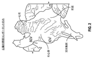
図1および2は、心臓の内部ボリュームのモデルを示し、特に、右心房(RA)ならびに右心耳(RAA)の幾何学形状および向きを図示する。図1では、心臓の内部全体が、右側から示される一方、図2は、心臓の脱酸素化血液領域(例えば、心臓、大静脈、肺動脈等の右側)のみを示す。示されるように、RAおよびRAAは、カテーテルデバイスの送達を妨害し得る多くの小襞、フラップ、ならびに裂け目を形成する不規則な内壁表面を含む。 Figures 1 and 2 show models of the internal volume of the heart, in particular illustrating the geometry and orientation of the right atrium (RA) and right atrial appendage (RAA). In FIG. 1, the entire interior of the heart is shown from the right side, while FIG. 2 shows only the oxygen scavenging blood region of the heart (eg, the right side of the heart, vena cava, pulmonary artery, etc.). As shown, RA and RAA include many folds, flaps, and irregular inner wall surfaces that form crevices that can interfere with the delivery of the catheter device.
開示される送達カテーテルは、下大静脈を介して、大腿静脈からRAAに到達し、RAA内の貫通場所において、カテーテルの遠位端を心膜空間の平面と略平行に位置付け、貫通デバイスを右冠動脈、大動脈、肺動脈、および左心耳を回避する方向に向け、そのような構造への傍近傷害を防止することを促進し、RAAの頭側壁を通して心膜空間の中に入るために十分な硬さを提供する3次元曲率を有する。 The disclosed delivery catheter reaches the RAA from the femoral vein via the inferior vena cava, positioning the distal end of the catheter approximately parallel to the plane of the pericardial space at the penetration site within the RAA and placing the penetration device on the right. Directed to avoid the coronary, aorta, pulmonary, and left atrial appendages, to help prevent near injury to such structures, and hard enough to enter the pericardial space through the cranial wall of the RAA. It has a three-dimensional curvature that provides the vein.
図3は、IVCを通して、RAを通して、RAAの中に延びている、例示的湾曲カテーテル10を図示する。開示されるカテーテルは、図4に図示されるように、3つの区画を含む。第1の近位区画12は、略直線または若干湾曲し、IVCを通して略垂直に突出することができる。第2の遷移区画13は、大静脈−心房接合部の近傍に位置付けられ、患者の右および正面側に向かって湾曲することができる。図4に示されるように、カテーテル10は、遷移区画13において、垂直z−軸の背後を通過し、次いで、第3の遠位区画14において、z−軸の周囲で湾曲し、z−軸の前を通り、遠位区画14は、カテーテルが使用のために位置付けられると、カテーテルの遠位端18まで患者の左側に向かってより鋭的に湾曲する。遠位区画10はまた、略直線部分16を遠位端に含むことができ、それは、患者内を略横断して延びることができる。
FIG. 3 illustrates an exemplary
遷移区画13および遠位区画14は、近位区画12から直線遠位部分16に向かって時計回りに渦巻状である。渦巻または螺旋曲率は、直線垂直z−軸を参照して、図4に図示される。用語「渦巻」および「螺旋」は、本明細書では同義的に使用され、曲率が中心軸の方向にも延びるように中心軸の周囲を湾曲する任意の3次元曲率を意味するように本明細書では広義に定義され、そのような用語は、曲率が、中心軸から一定半径(円形螺旋におけるように)、中心軸に対して一定ピッチまたは接線角度(いくつかの螺旋におけるように)、中心軸から継続的に増加または減少する半径(いくつかの渦巻におけるように)、直線中心軸、または中心軸の周囲における任意の最小弧長を有することを要求しないが、全てのそのような種も、この定義内に含まれる。用語「時計回り」は、カテーテルが右掌性を伴って湾曲することを意味し、カテーテルを垂直z−軸に沿って近位区画から上向きに/遠位に見た場合、時計回り曲率を伴うカテーテルは、略時計回り経路内で湾曲しているように見える。
The
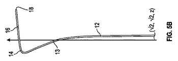
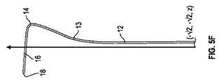
カテーテル10の曲率はさらに、z−軸の周囲で45°ずつの増分で得られた8つの側面立面図を示す、図5A−5Hに図示される。図5Aは、正面図であり、図5Bは、左正面図(図3および4の図に類似する)であり、図5Cは、左側面図であり、図5Dは、左背面図であり、図5Eは、背面図であり、図5Fは、右背面図であり、図5Gは、右側面図であり、図5Hは、左正面図である。図5A−5Hに示されるように、カテーテル10は、遷移区画13において右向きおよび前向きに湾曲する。カテーテル10は、次いで、遠位端18が左向きかつ若干上向きおよび後向きに突出するように、遠位区画14において左向きならびに後向きに湾曲する。この軌道は、カテーテルの遠位端および/またはカテーテル内で展開する貫通デバイスが、傍近傷害の最小限のリスクを伴って、RAAの頭側壁を通して心膜空間の中に入るように、RAA内で望ましく向けられることを可能にするように構成される。
The curvature of the
遷移区画13の右向き曲率(図5A)は、遷移区画にRAの右側壁に当接させることができる。遷移区画13および遠位区画14の前向き曲率(図5C参照)は、RAならびにRAAの前および/または上壁へのカテーテルの遠位区画14の密着を増加させるように構成され、近位区画12の略垂直向きから遠位区画14のより水平な向きへの平滑な遷移としての役割も果たす。いくつかの実施例では、遠位区画14は、近位区画12と略垂直な平面内において方向を合わせられることができる。遠位区画14は、大静脈−心房接合部を通過するより緩やかに湾曲する遷移区画13およびRAAの中に延びている略直線遠位部分16と比較して、カテーテルの前側面(カテーテルがRAおよびRAAの前ならびに/または上壁に当接する)においてより鋭的曲率(すなわち、より小さい曲率半径)を有することができる。RAおよびRAAの前ならびに/または上壁への遠位区画14の密着は、遠位端18に臓側心膜の接線平面と平行なRAAの頂部に沿って整列させ、RAAの頭側壁に当接させ、遠位端18は、右冠動脈およびその分岐から離れて位置付けられる。
The right-facing curvature of the transition compartment 13 (FIG. 5A) allows the transition compartment to abut against the right wall of the RA. The forward curvature of the
いくつかの実施例では、湾曲カテーテルの遠位区画14は、約2インチ〜約4インチ、約2.5インチ〜約3インチ、および/または約2.8インチの曲率半径を有することができる。いくつかの実施例では、湾曲カテーテルの遠位区画14は、約90°〜約180°、約120°〜約150°、および/または約135°の弧長を有することができる。
In some embodiments, the
図6および7は、カテーテル10に類似する、別の例示的湾曲カテーテル20を示す。図6は、背面図(図5Eに類似する)を示し、図7は、右側面図(図5Gに類似する)を示す。カテーテル20は、近位区画22と、遷移区画24と、遠位端30で終端する遠位区画26とを含む。近位区画22と遷移区画24とは、点32において接合され、遷移区画24と遠位区画26とは、点34において接合される。図6および7は、遷移区画24ならびに遠位区画26の例示的寸法を含む。例えば、点32から遠位端30までの直接距離は、約6インチであることができる。
6 and 7 show another exemplary
図8A−8Dは、心膜空間がRAAを介してアクセスされる例示的手技における4つの段階を示すX線画像である。図8Aでは、例示的湾曲カテーテル40が、IVCを通して延びているように位置付けられ、その遠位端50は、RA内にある。図8Bでは、遠位端50は、RAAの中に前進し、RAAの頭側壁または頂部52に当接している。この位置では、近位区画42は、IVC内にあり、遷移区画44は、大静脈−心房接合部を通してRAの中に入り、遠位区画46は、RAAの中に左向きに湾曲するにつれて、RAおよびRAAの前ならびに/または上壁に当接し、直線遠位部分48は、RAAを通して突出する。図8Cでは、貫通デバイス54が、カテーテルの遠位端50から展開され、略水平平面においてRAAの壁52を貫通し、心膜空間の中に入る。貫通デバイス54は、例えば、カテーテル40内から同軸方向に延びていることができる。いくつかの実施例では、貫通デバイスは、0.014インチワイヤを備えていることができる。図8Dは、カテーテル40からRAA内の貫通部を通して、心膜空間の中に延びている、例示的治療用デバイス56を示す。デバイス56は、貫通デバイス/ガイドワイヤ54の上を延びているマイクロカテーテルを含むことができる。デバイス56は、心膜空間内で手技を行うための種々のデバイスのいずれかを備えていることができる。
8A-8D are X-ray images showing four stages in an exemplary procedure in which the pericardial space is accessed via RAA. In FIG. 8A, the exemplary
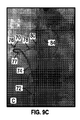
図9A−9Dは、心膜空間がRAAを介してアクセスされる別の例示的手技における4つの段階を示すX線画像である。図9Aでは、例示的湾曲カテーテル70が、IVCを通して延びて位置付けられ、その遠位端80は、RA内にある。図9Bでは、遠位端80は、RAAの中に前進し、RAAの頭側壁または頂部に当接している。この位置では、近位区画72は、IVC内にあり、遷移区画74は、大静脈−心房接合部を通してRAの中に入り、遠位区画76は、RAAの中に左向きに湾曲するにつれて、RAおよびRAAの前ならびに/または上壁に当接し、直線遠位部分78は、RAAを通して突出する。図9Cでは、貫通デバイス84は、カテーテル70の遠位端から展開され、略水平平面においてRAAの壁を貫通し、心膜空間の中に入る。貫通デバイス84は、ガイドワイヤを含むことができる。図9Dは、カテーテル50からRAA内の貫通部を通して心膜空間の中に延びている、例示的治療用デバイス86を示す。デバイス86は、貫通デバイス/ガイドワイヤ84の上を延びているマイクロカテーテルを含むことができる。デバイス86は、心膜空間内で手技を行うための種々のデバイスのいずれかを備えていることができる。
9A-9D are X-ray images showing four stages in another exemplary procedure in which the pericardial space is accessed via RAA. In FIG. 9A, an exemplary
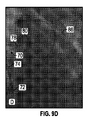
図10は、RAA100の頭側壁102を貫通するとき、開示される湾曲カテーテルがどのようにより望ましい交差軌道を提供し得るかを図示する。従来のカテーテルがRAおよびRAAを通して比較的に直線に突出する場合、交差軌道は、矢印104によって示されるように、より垂直に向けられる。RAAの向きは、有意な垂直傾きを伴ってRAから突出するRAAを示す図1および2にさらに図示されている。開示される湾曲カテーテルがない場合、交差軌道104は、類似垂直傾きを有し得る。軌道104は、RAA貫通デバイスが、あまりに遠くに容易に延び、心膜も貫通し得るように、心膜の平面に対して直角であるので、望ましくない。対照的に、開示される湾曲カテーテルは、遠位端が、貫通デバイスに、より水平かつ心膜の平面と平行である軌道106を与え、心膜を貫通するリスクを減少させるように、RAおよびRAAの前ならびに/または上壁に当接する。軌道106は、右冠動脈、肺動脈、および大動脈等の他の隣接する傍近構造を回避することにも役立つ。軌道106は、軌道104の場合のように、RAAの壁を交差後、鋭的旋回を行う必要なく、治療用デバイスをより平滑に心膜空間の中に向かわせることにも役立つ。
FIG. 10 illustrates how the disclosed curved catheter can provide a more desirable cross trajectory when penetrating the
従来の軌道104は、水平から約36°〜約72°であり得る一方、開示される軌道106は、水平から36°未満、水平から30°未満、および/または水平から25°未満であり得る。ここで使用される場合、「水平」は、患者の正面、背面、左、および右方向によって画定された横平面を意味する。
The
本明細書に開示されるカテーテル実施形態のいずれかはさらに、カテーテルの遠位端またはその近傍で膨張させられ、RAAの柱状突起壁(図1および2参照)を分離ならびに/または平坦化し、RAAの頂部および頭側壁に対する貫通デバイスの遠位密着を可能にし得る膨張可能バルーンカテーテルを含むことができ、それと共に使用されることができ、またはそれを同軸方向に送達することができる。これは、カテーテルをRAAの頂部に沿って頭側壁まで前進させながら、RAA内側の柱状突起による障害物を回避することに役立つことができる。そのようなバルーンカテーテルは、湾曲カテーテルがRAAを通して前進される間、任意の回数、膨張および収縮されることができる。 Any of the catheter embodiments disclosed herein are further inflated at or near the distal end of the catheter to separate and / or flatten the columnar protrusion wall of RAA (see FIGS. 1 and 2) and RAA. An inflatable balloon catheter that can allow distal adhesion of the penetrating device to the apex and cranial wall of the can be included and can be used with it, or it can be delivered coaxially. This can help avoid obstacles due to columnar processes inside the RAA while advancing the catheter along the crown of the RAA to the side wall of the head. Such balloon catheters can be inflated and deflated any number of times while the curved catheter is advanced through the RAA.
開示される実施形態のいずれかでは、湾曲カテーテルは、カテーテルが、RAA壁を貫通する間、貫通デバイスに印加される貫通力に対して対抗する抵抗を提供し得るように、十分な柱強度を提供するように構築されることができる。 In any of the disclosed embodiments, the curved catheter is provided with sufficient column strength so that the catheter can provide resistance against the penetrating force applied to the penetrating device while penetrating the RAA wall. Can be built to provide.
本明細書に開示されるカテーテル、システム、および方法のいずれかに関して、類似実施形態が、上大静脈(SVC)からの送達において使用するために構成されることができる。そのようなデバイスでは、カテーテルは、RAの右側壁に当接し、次いで、RA/RAAの前および上壁に向かって、ならびにそれに対して上向きに、前向きおよび左向きに逆湾曲し、次いで、RAAを通して若干後向き、左向きおよび上向きに湾曲するように、SVCならびにRAの接合部において、若干右向き、前向き、および下向きに湾曲することができる。 With respect to any of the catheters, systems, and methods disclosed herein, similar embodiments can be configured for use in delivery from the superior vena cava (SVC). In such devices, the catheter abuts on the right wall of the RA and then reversely curves toward the anterior and superior walls of the RA / RAA and upwards, forwards and leftward, and then through the RAA. It can be curved slightly to the right, forward, and downward at the joints of the SVC and RA so that it curves slightly backward, left and upward.
本説明の目的のために、本開示の実施形態のある側面、利点、および新規特徴が、本明細書に説明される。開示される方法、装置、およびシステムは、いかようにも限定として解釈されるべきではない。代わりに、本開示は、単独ならびに相互の種々の組み合わせおよび部分的組み合わせにおける、種々の開示される実施形態のあらゆる新規および非自明特徴ならびに側面を対象とする。方法、装置、およびシステムは、任意の具体的側面または特徴もしくはそれらの組み合わせに限定されず、開示される実施形態は、任意の1つ以上の具体的利点が存在する、もしくは問題が解決されることを要求しない。 For the purposes of this description, certain aspects, advantages, and novel features of embodiments of the present disclosure are described herein. The disclosed methods, devices, and systems should not be construed as limiting in any way. Instead, the present disclosure covers all novel and non-trivial features and aspects of the various disclosed embodiments, in various combinations and partial combinations, alone and with each other. The methods, devices, and systems are not limited to any specific aspects or features or combinations thereof, and the disclosed embodiments have any one or more specific advantages or problems are solved. Does not require that.
開示される発明の特定の側面、実施形態、または実施例と併せて説明される、特徴、整数、群、寸法、材料、化合物、もしくは他の特性は、それらと非互換性ではない限り、本明細書に説明される任意の他の側面、実施形態、または実施例に適用可能であることを理解されたい。本明細書(任意の付随の請求項、要約、および図面を含む)に開示される特徴は全て、および/またはそのように開示される任意の方法もしくはプロセスのステップは全て、そのような特徴および/またはステップのうちの少なくともいくつかが相互に排他的である組み合わせを除き、任意の組み合わせにおいて組み合わせられてもよい。本発明は、任意の前述の実施形態の詳細に制限されない。本発明は、本明細書(任意の付随の請求項、要約、および図面を含む)に開示される特徴の任意の新規のものもしくは任意の新規の組み合わせ、またはそのように開示される任意の方法もしくはプロセスのステップ任意の新規のものもしくは任意の新規組み合わせにわたる。 The features, integers, groups, dimensions, materials, compounds, or other properties described in conjunction with the disclosed aspects, embodiments, or examples of the invention are described in the book unless they are incompatible with them. It should be understood that it is applicable to any other aspect, embodiment, or embodiment described herein. All features disclosed herein, including any accompanying claims, abstracts, and drawings, and / or any steps in any method or process so disclosed, such features and / Or may be combined in any combination, except for combinations in which at least some of the steps are mutually exclusive. The present invention is not limited to the details of any of the aforementioned embodiments. The present invention is in any novel or any novel combination of features disclosed herein, including any accompanying claims, abstracts, and drawings, or any method so disclosed. Or the steps of the process span any new or any new combination.
開示される方法のうちのいくつかの動作が、便宜的提示のために、特定の順次的順序で説明されるが、本説明の様式は、特定の順序が具体的言語によって要求されない限り、並べ替えを包含するものと理解されたい。例えば、連続して説明される動作は、ある場合には、並べ替えられる、または並行して行われ得る。さらに、簡潔にするために、添付の図は、開示される方法が他の方法と共に使用され得る種々の方法を示さない場合がある。本明細書で使用されるように、用語「1つの(a、an)」および「少なくとも1つ」は、規定された要素のうちの1つ以上のものを包含する。すなわち、特定の要素のうちの2つが存在する場合、これらの要素のうちの1つもまた、存在し、したがって、「1つの」要素が、存在する。用語「複数の(a plurality ofおよびplural)」は、規定された要素のうちの2つまたはそれを上回るものを意味する。 Some actions of the disclosed methods are described in a particular sequential order for convenience of presentation, but the forms of this description are ordered unless a particular order is required by the specific language. It should be understood to include replacement. For example, the actions described in succession can be rearranged or performed in parallel in some cases. Further, for brevity, the attached figures may not show the various methods in which the disclosed methods can be used in conjunction with other methods. As used herein, the terms "one (a, an)" and "at least one" include one or more of the defined elements. That is, if two of the particular elements are present, then one of these elements is also present, and thus a "one" element is present. The term "plurality of and plural" means two or more of the defined elements.
本明細書で使用されるように、要素のリストの最後の2つ間で使用される、用語「および/または」は、列挙された要素のうちの任意の1つ以上のものを意味する。例えば、語句「A、B、および/またはC」は、「A」、「B」、「C」、「AおよびB」、「AおよびC」、「BおよびC」、または「A、B、およびC」を意味する。本明細書で使用されるように、用語「結合される」は、具体的対照言語がない場合、概して、物理的に、磁気的に、化学的に、電気的に、または別様に結合もしくは連結されることを意味し、結合されるアイテム間の中間要素の存在を除外しない。 As used herein, the term "and / or" used between the last two in a list of elements means any one or more of the listed elements. For example, the phrase "A, B, and / or C" is "A," "B," "C," "A and B," "A and C," "B and C," or "A, B." , And C ”. As used herein, the term "bonded" generally means physically, magnetically, chemically, electrically, or otherwise, in the absence of a specific control language. It means that they are concatenated and does not exclude the existence of intermediate elements between the items to be combined.
開示される技術の原理が適用され得る、多くの可能性として考えられる実施形態に照らして、図示される実施形態は、実施例にすぎないことが認識され、本開示の範囲の限定と見なされるべきではない。むしろ、本開示の範囲は、少なくとも、以下の請求項およびその均等物と同等範囲である。 In light of the many possible embodiments to which the principles of the disclosed technology can be applied, it is recognized that the illustrated embodiments are only examples and are considered to be a limitation of the scope of the present disclosure. Should not be. Rather, the scope of the present disclosure is at least equivalent to the following claims and their equivalents.
Claims (16)
近位区画と、前記近位区画から遠位に延びている遷移区画と、前記遷移区画から遠位に延びている遠位区画と、遠位端とを備え、
前記カテーテルは、前記近位区画と実質的に平行に延在する中心軸の周りで前記中心軸に沿って延在し、前記近位区画は、外力がないときに、前記中心軸に関して前記遠位区画から横方向および長手方向にオフセットされており、
前記遷移区画および前記遠位区画は、少なくとも、前記カテーテルに外力がないとき、かつ、前記カテーテルが患者内に位置付けられる前に、前記中心軸の周りで時計回りの3次元の渦巻曲率を伴って、前記近位区画から延びるように構成されており、前記時計回りの3次元の渦巻曲率は、右掌性を備え、これにより、前記カテーテルは、前記カテーテルを前記近位区画から前記中心軸に沿って遠位方向に見たときに略時計回りの経路で湾曲し、前記カテーテルが前記患者内に位置付けられると、前記時計回りの3次元の渦巻曲率は、
前記近位区画が、下大静脈内に位置付けられ、
前記遷移区画が、大静脈−心房接合部を横断して延び、前記カテーテルが右心房の右側壁に当接するように、右向き、前向き、および上向きに湾曲し、
前記遠位区画が、前記カテーテルが前記RAAに隣接して右心房の前壁に当接するように、前記遷移区画から前記右心房を通して左向き、前向き、および上向きに湾曲し、前記遠位区画が、前記カテーテルの遠位端が前記RAAの頭側壁に接触するように、前記右心房の前壁から前記RAAの前上壁に沿って左向き、後向き、および上向きに湾曲し続ける
ように維持され、
前記カテーテルは、同軸の貫通デバイスが前記カテーテルの遠位端から延び、前記RAAの頭側壁を貫通し、前記心膜空間の中に入るように誘導するように構成され、
前記時計回りの3次元の渦巻曲率は、前記カテーテルの遠位端を略左向き、かつ前記心膜と平行に向くように向け、それによって、前記貫通デバイスは、前記心膜を損傷せずに、右冠動脈、肺動脈、および大動脈から間隔を置かれた場所において、前記RAAの頭側壁を通過して前記心膜空間の中に入る、カテーテル。 A transvascular catheter for accessing the pericardial space from within the right atrial appendage (RAA) of the heart.
It comprises a proximal compartment, a transition compartment distal to the proximal compartment, a distal compartment extending distally from the transition compartment, and a distal end.
The catheter extends along the central axis around a central axis that extends substantially parallel to the proximal compartment, the proximal compartment being said far with respect to the central axis in the absence of external force. Offset laterally and longitudinally from the position compartment
The transition compartment and the distal compartment are accompanied by a three-dimensional spiral curvature clockwise around the central axis , at least when the catheter has no external force and before the catheter is positioned within the patient. , The clockwise three-dimensional spiral curvature is right palmar, which allows the catheter to move the catheter from the proximal compartment to the central axis. When viewed distally along, it curves in a substantially clockwise path, and when the catheter is positioned within the patient, the clockwise three-dimensional spiral curvature
The proximal compartment is located within the inferior vena cava and
The transition compartment extends across the vena cava-atrial junction and curves right, anteriorly, and upward so that the catheter abuts on the right wall of the right atrium.
The distal compartment curves left, forward, and upward from the transition compartment through the right atrium so that the catheter abuts the anterior wall of the right atrium adjacent to the RAA. The distal end of the catheter is maintained to continue to curve leftward, posterior, and upward along the anterior superior wall of the RAA from the anterior wall of the right atrium so that it contacts the cranial wall of the RAA.
The catheter is configured such that a coaxial penetrating device extends from the distal end of the catheter, penetrates the head wall of the RAA, and guides it into the pericardial space.
The clockwise three-dimensional spiral curvature directs the distal end of the catheter approximately to the left and parallel to the pericardium, whereby the penetrating device does not damage the pericardium. A catheter that passes through the cranial wall of the RAA and enters the pericardial space at a distance from the right coronary artery, pulmonary artery, and aorta.
カテーテルであって、前記カテーテルは、近位区画と、前記近位区画から遠位に延びている遷移区画と、前記遷移区画から遠位に延びている遠位区画と、遠位端とを備え、
前記カテーテルは、前記近位区画と実質的に平行に延在する中心軸の周りで前記中心軸に沿って延在し、前記近位区画は、外力がないときに、前記中心軸に関して前記遠位区画から横方向および長手方向にオフセットされており、
前記遷移区画および前記遠位区画は、少なくとも、前記カテーテルに外力がないとき、かつ、前記カテーテルが前記患者内に位置付けられる前に、前記中心軸の周りで時計回りの3次元の渦巻曲率を伴って前記近位区画から延びるように構成され、前記時計回りの3次元の渦巻曲率は、右掌性を備え、これにより、前記カテーテルは、前記カテーテルを前記近位区画から前記中心軸に沿って遠位方向に見たときに略時計回りの経路で湾曲し、前記カテーテルが前記患者内に位置付けられると、前記時計回りの3次元の渦巻曲率は、
前記近位区画が、下大静脈内に位置付けられ、
前記遷移区画が、大静脈−心房接合部を横断して延び、前記カテーテルが右心房の右側壁に当接するように、右向き、前向き、および上向きに湾曲し、
前記遠位区画が、前記カテーテルが前記RAAに隣接して前記右心房の前壁に当接するように、前記遷移区画から前記右心房を通して左向き、前向き、および上向きに湾曲し、前記遠位区画が、前記カテーテルの遠位端が前記RAAの頭側壁に接触するように、前記右心房の前壁から前記RAAの前上壁に沿って左向き、後向き、および上向きに湾曲し続ける
ように維持される、カテーテルと、
前記カテーテルと同軸の貫通デバイスであって、前記カテーテルは、前記貫通デバイスが前記RAAの頭側壁を貫通して前記心膜空間の中に入るように、前記貫通デバイスを前記カテーテルを通して前記カテーテルの遠位端から外へ送達するように構成されている、貫通デバイスと
を備え、
前記時計回りの3次元の渦巻曲率は、前記カテーテルの遠位端を略左向き、かつ前記心膜と平行に向くように向け、それによって、前記貫通デバイスは、前記心膜を損傷せずに、右冠動脈、肺動脈、および大動脈から間隔を置かれた場所において、前記RAAの頭側壁を通過して前記心膜空間の中に入る、システム。 A system that accesses the pericardial space from within the right atrial appendage (RAA) of the patient's heart.
A catheter, the catheter comprising a proximal compartment, a transition compartment distal to the proximal compartment, a distal compartment extending distally from the transition compartment, and a distal end. ,
The catheter extends along the central axis around a central axis that extends substantially parallel to the proximal compartment, the proximal compartment being said far with respect to the central axis in the absence of external force. Offset laterally and longitudinally from the position compartment
Said transition compartment and said distal compartment, with at least, when there is no external force to the catheter and before the catheter is positioned within said patient, a 3-dimensional spiral curvature clockwise around the central axis Extending from the proximal compartment, the clockwise three-dimensional spiral curvature provides right palmarity, which allows the catheter to move the catheter from the proximal compartment along the central axis. When viewed distally, it curves in a substantially clockwise path, and when the catheter is positioned within the patient, the clockwise three-dimensional spiral curvature
The proximal compartment is located within the inferior vena cava and
The transition compartment extends across the vena cava-atrial junction and curves right, anteriorly, and upward so that the catheter abuts on the right wall of the right atrium.
The distal compartment curves left, forward, and upward from the transition compartment through the right atrium so that the catheter abuts the anterior wall of the right atrium adjacent to the RAA, and the distal compartment The catheter is maintained to continue to bend leftward, posterior, and upward along the anterior superior wall of the RAA from the anterior wall of the right atrium so that the distal end of the catheter contacts the cranial wall of the RAA. , Catheter and
A penetrating device coaxial with the catheter, the catheter is distant from the catheter through the catheter so that the penetrating device penetrates the head wall of the RAA and enters the pericardial space. Equipped with a penetration device that is configured to deliver from the end of the position
The clockwise three-dimensional spiral curvature directs the distal end of the catheter approximately to the left and parallel to the pericardium, whereby the penetrating device does not damage the pericardium. A system that passes through the cranial wall of the RAA and enters the pericardial space at a location spaced from the right coronary artery, pulmonary artery, and aorta.
前記カテーテルは、それを通して前記バルーンカテーテルを送達するように構成され、
前記バルーンカテーテルは、前記RAA内で膨張し、前記RAA内の柱状突起を分離または平坦化するように構成され、
前記カテーテルの遠位端は、前記分離または平坦化された柱状突起を越えて前記RAAの頭側壁に前進するように構成されている、請求項8に記載のシステム。 With more balloon catheters
The catheter is configured to deliver the balloon catheter through it.
The balloon catheter is configured to inflate within the RAA and separate or flatten the columnar processes within the RAA.
8. The system of claim 8, wherein the distal end of the catheter is configured to advance over the separated or flattened columnar process to the head wall of the RAA.
Applications Claiming Priority (3)
| Application Number | Priority Date | Filing Date | Title |
|---|---|---|---|
| US201562162453P | 2015-05-15 | 2015-05-15 | |
| US62/162,453 | 2015-05-15 | ||
| PCT/US2016/031461 WO2016186880A1 (en) | 2015-05-15 | 2016-05-09 | Three-dimensional right atrial appendage curve catheter |
Publications (3)
| Publication Number | Publication Date |
|---|---|
| JP2018521713A JP2018521713A (en) | 2018-08-09 |
| JP2018521713A5 JP2018521713A5 (en) | 2019-06-06 |
| JP6937700B2 true JP6937700B2 (en) | 2021-09-22 |
Family
ID=57320407
Family Applications (1)
| Application Number | Title | Priority Date | Filing Date |
|---|---|---|---|
| JP2017559396A Active JP6937700B2 (en) | 2015-05-15 | 2016-05-09 | 3D right atrial appendage curved catheter |
Country Status (5)
| Country | Link |
|---|---|
| US (1) | US11173278B2 (en) |
| EP (1) | EP3294400A4 (en) |
| JP (1) | JP6937700B2 (en) |
| CN (1) | CN107810028B (en) |
| WO (1) | WO2016186880A1 (en) |
Families Citing this family (3)
| Publication number | Priority date | Publication date | Assignee | Title |
|---|---|---|---|---|
| JP7180971B2 (en) | 2017-09-21 | 2022-11-30 | テルモ株式会社 | Catheters and catheter assemblies |
| US11471190B2 (en) * | 2018-04-02 | 2022-10-18 | Cardiac Pacemakers, Inc. | Bundle of his lead delivery catheter, system and method |
| WO2021117220A1 (en) * | 2019-12-13 | 2021-06-17 | 日本ライフライン株式会社 | Catheter |
Family Cites Families (23)
| Publication number | Priority date | Publication date | Assignee | Title |
|---|---|---|---|---|
| US5195990A (en) * | 1991-09-11 | 1993-03-23 | Novoste Corporation | Coronary catheter |
| US5269326A (en) | 1991-10-24 | 1993-12-14 | Georgetown University | Method for transvenously accessing the pericardial space via the right auricle for medical procedures |
| US5575766A (en) | 1993-11-03 | 1996-11-19 | Daig Corporation | Process for the nonsurgical mapping and treatment of atrial arrhythmia using catheters guided by shaped guiding introducers |
| US5690611A (en) | 1994-07-08 | 1997-11-25 | Daig Corporation | Process for the treatment of atrial arrhythima using a catheter guided by shaped giding introducers |
| US5797870A (en) * | 1995-06-07 | 1998-08-25 | Indiana University Foundation | Pericardial delivery of therapeutic and diagnostic agents |
| US5968010A (en) | 1997-04-30 | 1999-10-19 | Beth Israel Deaconess Medical Center, Inc. | Method for transvenously accessing the pericardial space via the right atrium |
| US6200303B1 (en) * | 1997-04-30 | 2001-03-13 | Beth Israel Deaconess Medical Center, Inc. | Method and kit for transvenously accessing the pericardial space via the right atrium |
| US6132417A (en) * | 1997-08-22 | 2000-10-17 | Scheider/Namic | Right coronary artery catheter |
| US20050234436A1 (en) * | 1999-07-14 | 2005-10-20 | Cardiofocus, Inc. | Methods of cardiac ablation in the vicinity of the right inferior pulmonary vein |
| US20050234437A1 (en) * | 1999-07-14 | 2005-10-20 | Cardiofocus, Inc. | Deflectable sheath catheters with out-of-plane bent tip |
| US20050154370A1 (en) | 1999-10-29 | 2005-07-14 | Medtronic, Inc. | Methods and systems for providing therapies into the pericardial space |
| JP4138583B2 (en) * | 2002-08-08 | 2008-08-27 | テルモ株式会社 | Guide wire |
| US7226440B2 (en) * | 2005-01-31 | 2007-06-05 | G & L Consulting, Llc | Method and device for accessing a pericardial space |
| WO2006091597A1 (en) | 2005-02-22 | 2006-08-31 | Cardiofocus, Inc. | Deflectable sheath catheters |
| US20100069849A1 (en) | 2006-06-30 | 2010-03-18 | Kassab Ghassan S | Percutaneous intravascular access to cardiac tissue |
| US8366707B2 (en) | 2007-01-23 | 2013-02-05 | Cvdevices Llc | Systems and methods for epicardial navigation |
| US10166066B2 (en) | 2007-03-13 | 2019-01-01 | University Of Virginia Patent Foundation | Epicardial ablation catheter and method of use |
| JP5174891B2 (en) | 2007-04-27 | 2013-04-03 | シーヴィ デヴァイシズ,エルエルシー | Devices, systems, and methods for accessing the epicardial surface of the heart |
| EP2308550B1 (en) * | 2009-10-07 | 2016-01-13 | Sorin CRM SAS | Epicardial stimulation/defibrillation probe with screw, suitable for implantation via a catheter-guide inserted in the pericardial cavity |
| EP2558014A4 (en) * | 2010-04-13 | 2017-11-29 | Sentreheart, Inc. | Methods and devices for treating atrial fibrillation |
| US9072872B2 (en) * | 2010-10-29 | 2015-07-07 | Medtronic, Inc. | Telescoping catheter delivery system for left heart endocardial device placement |
| WO2013013098A1 (en) * | 2011-07-19 | 2013-01-24 | Adagio Medical, Inc. | System and method for creation of cox maze lesions |
| ES2691478T3 (en) | 2012-10-22 | 2018-11-27 | The Cleveland Clinic Foundation | Apparatus for acting on a body tissue |
-
2016
- 2016-05-09 CN CN201680027776.XA patent/CN107810028B/en active Active
- 2016-05-09 US US15/571,342 patent/US11173278B2/en active Active
- 2016-05-09 WO PCT/US2016/031461 patent/WO2016186880A1/en active Application Filing
- 2016-05-09 EP EP16796939.3A patent/EP3294400A4/en active Pending
- 2016-05-09 JP JP2017559396A patent/JP6937700B2/en active Active
Also Published As
| Publication number | Publication date |
|---|---|
| JP2018521713A (en) | 2018-08-09 |
| WO2016186880A1 (en) | 2016-11-24 |
| US11173278B2 (en) | 2021-11-16 |
| EP3294400A1 (en) | 2018-03-21 |
| CN107810028A (en) | 2018-03-16 |
| US20180214667A1 (en) | 2018-08-02 |
| CN107810028B (en) | 2021-06-25 |
| EP3294400A4 (en) | 2019-01-23 |
Similar Documents
| Publication | Publication Date | Title |
|---|---|---|
| CN111163701B (en) | Delivery systems and methods for reshaping a heart valve annulus including the use of magnetic tools | |
| US9011531B2 (en) | Method and apparatus for repairing a mitral valve | |
| US9763666B2 (en) | Left atrial appendage plugging device and delivery system | |
| US6945978B1 (en) | Heart valve catheter | |
| US20140066895A1 (en) | Anatomic device delivery and positioning system and method of use | |
| US10076414B2 (en) | Method and apparatus for repairing a mitral valve | |
| US11369405B2 (en) | Method and septostomy device for creating an interatrial aperture | |
| CA3052806A1 (en) | Transcatheter device for interatrial anastomosis | |
| CN111601633A (en) | Transseptal guide wire puncture system | |
| US20150134057A1 (en) | Method and apparatus for repairing a mitral valve | |
| US20220151647A1 (en) | Catheters having shaped distal portions, and associated systems and methods | |
| JP6937700B2 (en) | 3D right atrial appendage curved catheter | |
| JP2014517717A (en) | Guiding catheter | |
| US11925554B1 (en) | Method and apparatus for antegrade transcatheter valve repair or implantation | |
| US20240081846A1 (en) | Devices and methods for treating blocked blood vessels | |
| US20150119853A1 (en) | Convertible Shape Catheter And Method Of Use | |
| JP2022539446A (en) | Transseptal system, device and method | |
| JP2018521713A5 (en) | ||
| US20170348004A1 (en) | Methods, systems and devices for treating orthostatic intolerance | |
| US20230181214A1 (en) | Method and septostomy device for creating an interatrial aperture | |
| Kundu et al. | Catheterization of the cardiac venous system | |
| Gurley | Catheterization of the cardiac venous system | |
| EP4340757A1 (en) | Securing a guidewire delivery catheter in the coronary sinus using a mechanically releasing arm | |
| MARTINEZ et al. | TRANSSEPTAL PUNCTURE | |
| Stratos et al. | Percutaneous Mitral Valvuloplasty Refined: Use of a Novel Modified Antegrade Approach |
Legal Events
| Date | Code | Title | Description |
|---|---|---|---|
| A521 | Request for written amendment filed |
Free format text: JAPANESE INTERMEDIATE CODE: A523 Effective date: 20190425 |
|
| A621 | Written request for application examination |
Free format text: JAPANESE INTERMEDIATE CODE: A621 Effective date: 20190425 |
|
| A977 | Report on retrieval |
Free format text: JAPANESE INTERMEDIATE CODE: A971007 Effective date: 20200310 |
|
| A131 | Notification of reasons for refusal |
Free format text: JAPANESE INTERMEDIATE CODE: A131 Effective date: 20200406 |
|
| A521 | Request for written amendment filed |
Free format text: JAPANESE INTERMEDIATE CODE: A523 Effective date: 20200703 |
|
| A131 | Notification of reasons for refusal |
Free format text: JAPANESE INTERMEDIATE CODE: A131 Effective date: 20201225 |
|
| A521 | Request for written amendment filed |
Free format text: JAPANESE INTERMEDIATE CODE: A523 Effective date: 20210325 |
|
| TRDD | Decision of grant or rejection written | ||
| A01 | Written decision to grant a patent or to grant a registration (utility model) |
Free format text: JAPANESE INTERMEDIATE CODE: A01 Effective date: 20210730 |
|
| A601 | Written request for extension of time |
Free format text: JAPANESE INTERMEDIATE CODE: A601 Effective date: 20210827 |
|
| A61 | First payment of annual fees (during grant procedure) |
Free format text: JAPANESE INTERMEDIATE CODE: A61 Effective date: 20210831 |
|
| R150 | Certificate of patent or registration of utility model |
Ref document number: 6937700 Country of ref document: JP Free format text: JAPANESE INTERMEDIATE CODE: R150 |