JP2004176945A - Hot gas cooling device and its method - Google Patents

Hot gas cooling device and its method Download PDF

Info

Publication number
JP2004176945A
JP2004176945A JP2002340660A JP2002340660A JP2004176945A JP 2004176945 A JP2004176945 A JP 2004176945A JP 2002340660 A JP2002340660 A JP 2002340660A JP 2002340660 A JP2002340660 A JP 2002340660A JP 2004176945 A JP2004176945 A JP 2004176945A
Authority
JP
Japan
Prior art keywords
cooling
gas
temperature gas
cooling device
tray
Prior art date
Legal status (The legal status is an assumption and is not a legal conclusion. Google has not performed a legal analysis and makes no representation as to the accuracy of the status listed.)
Pending
Application number
JP2002340660A
Other languages
Japanese (ja)
Inventor
Michitoshi Shimizu
通俊 清水
Seiji Akeki
精治 明木
Current Assignee (The listed assignees may be inaccurate. Google has not performed a legal analysis and makes no representation or warranty as to the accuracy of the list.)
NITSUSHIYOO KIKO KK
Original Assignee
NITSUSHIYOO KIKO KK
Priority date (The priority date is an assumption and is not a legal conclusion. Google has not performed a legal analysis and makes no representation as to the accuracy of the date listed.)
Filing date
Publication date
Application filed by NITSUSHIYOO KIKO KK filed Critical NITSUSHIYOO KIKO KK
Priority to JP2002340660A priority Critical patent/JP2004176945A/en
Publication of JP2004176945A publication Critical patent/JP2004176945A/en
Pending legal-status Critical Current

Links

Images

Classifications

    • YGENERAL TAGGING OF NEW TECHNOLOGICAL DEVELOPMENTS; GENERAL TAGGING OF CROSS-SECTIONAL TECHNOLOGIES SPANNING OVER SEVERAL SECTIONS OF THE IPC; TECHNICAL SUBJECTS COVERED BY FORMER USPC CROSS-REFERENCE ART COLLECTIONS [XRACs] AND DIGESTS
    • Y02TECHNOLOGIES OR APPLICATIONS FOR MITIGATION OR ADAPTATION AGAINST CLIMATE CHANGE
    • Y02EREDUCTION OF GREENHOUSE GAS [GHG] EMISSIONS, RELATED TO ENERGY GENERATION, TRANSMISSION OR DISTRIBUTION
    • Y02E20/00Combustion technologies with mitigation potential
    • Y02E20/30Technologies for a more efficient combustion or heat usage

Abstract

<P>PROBLEM TO BE SOLVED: To provide a hot gas cooling device for preventing the re-synthesis of dioxine by rapidly cooling hot gas from a combustion temperature to 200°C or lower in a residence time of one-to-two seconds or less, and to provide its cooling method. <P>SOLUTION: The hot gas cooling device comprises a cubic cooling device body 3 having a wall inside, a gas inlet portion 25 provided in an upper region of the cooling device body 3 for introducing hot gas 23, a plurality of trays 5 having peripheral members for storing cooling water 17, a granular neutralizing agent contained filtering device 9 having a plurality of porous opening portions 39 made at certain pitches avoiding the drop of a granular neutralizing agent down to the trays 5, a water tank 21 provided at the lowest portion of the cooling device body 3 for storing the cooling water 17 flowing down from the granular neutralizing agent contained filtering device 9, a circulation pump 13 for returning the cooling water 17 stored in the water tank 21 via a circulation water pipe 15 to the uppermost tray 5, and a gas outlet portion 27 provided in a lower region of the cooling device body 3 for exhausting cold gas 41. <P>COPYRIGHT: (C)2004,JPO

Description

【0001】
【発明が属する技術分野】
本発明は、高温ガスの冷却装置およびその冷却方法、特に、焼却炉,溶融炉,電気炉,内燃機関などの燃焼装置から排出される大量の高温ガスを急冷して、環境対策に必要なダイオキシン類などの再合成を防止するようにした高温ガスの冷却装置およびその冷却方法に関するものである。
【0002】
【従来の技術】
従来、燃焼装置から排出される高温ガスの急冷は環境対策として、煤塵の捕集の前操作および、ダイオキシン類を減らすために必要な操作であり、高温ガスを高性能の熱交換器を用いて熱回収・冷却を行う間接的な冷却手段か、あるいは高温ガス中に冷却水を直接噴霧・接触させて蒸発潜熱による冷却を行う直接的な冷却手段によって行われていた。
【0003】
前述した間接的な冷却手段としては、例えばボイラ型熱交換器に見られるように、高温ガスの持つ高い顕熱を効率よく冷却するために、一般的に伝熱面積を増やしたり、あるいは熱伝導率の高い材質を用いることが行われている。
他方、直接的な冷却手段としては、特開平11−22953号公報に記載してあるように、水を直接噴霧・接触させて蒸発潜熱による冷却を行うこと、また特開平11−9962号公報に記載してあるように、湿式スクラバーにより冷却を行うこと、さらに特開平09−294918号公報に記載してあるように、水中へ高温ガスを吹き込んでバブリング冷却を行うことなどが知られている。
【0004】
【特許文献1】
特開平11−9962号公報
【特許文献2】
特開平9−294918号公報
【0005】
【発明が解決しようとする課題】
しかしながら、前者の間接的な冷却手段の場合は、伝熱面積が大きくかつ熱伝導率の高い材質を用いることは、大型で高価な装置となったり、あるいは900℃の高温ガス温度から200℃までの温度まで冷却しようとすると、5〜20秒の滞留時間を要するため、ダイオキシン類が再合成しやすいといった問題があった。
【0006】
さらに、後者の直接的な冷却手段の場合は、
(1)高温ガス温度から200℃までの温度まで冷却しようとすると、3〜20秒の滞留時間を要するため、ダイオキシン類が再合成しやすいこと。
(2)水の直接噴霧形式では、噴霧用の動力が無視できないほど大きいこと。
(3)さらに、飛沫同伴を生じやすく冷却後の集塵に制約があること。
などの問題があった。
【0007】
本発明は、上記問題点に鑑みてなされたものであり、その目的は、高温ガスを滞留時間1〜2秒以下で燃焼温度から200℃以下に急冷し、ダイオキシンの再合成を防止することのできる高温ガスの冷却装置およびその冷却方法を提供することにある。
【0008】
【発明が解決するための手段】
上記課題を解決するために、本発明に係る第1の発明では、前工程の燃焼装置から排出された高温ガスを冷却する高温ガスの冷却装置であって、内部に壁体を有する立方体状の冷却装置躯体と、該冷却装置躯体の上部域に設けられた該高温ガスを導入するためのガス入口部と、冷却水を貯留するために周辺部材を有する複数のトレイと、該トレイの下方に複数の多孔状の開口部を有する粒状中和剤入り濾過装置と、該粒状中和剤入り濾過装置より流下した該冷却水を貯留するために該冷却装置躯体の最下部に設けられた水槽と、該水槽に貯留した該冷却水を循環水配管を介して最上段の該トレイに戻すための循環ポンプと、該冷却装置躯体の下部域に設けられた低温ガスを排出するためのガス出口部とで構成した。
【0009】
本発明に係る第2の発明では、前工程の燃焼装置から排出された高温ガスを冷却装置躯体のガス入口部を介して導入し、複数の皿状容器を有するトレイ内に冷却水をオーバーフローにより逐次流下させて該高温ガスと該冷却水を並流にしつつ該高温ガスを冷却し、該高温ガスが粒状中和剤入り濾過装置の下部側を通過する際に十字流にて冷却した後、該冷却装置躯体のガス出口部から低温ガスを排出するとともに、該粒状中和剤入り濾過装置より流下した該冷却水は一旦水槽に貯留した後、濾過装置と循環ポンプから循環水配管を介して最上段の該トレイに戻すようにした。
【0010】
本発明に係る第3の発明では、前工程の燃焼装置から排出された高温ガスを冷却する高温ガスの冷却装置であって、内部に壁体を有する立方体状の冷却装置躯体と、該冷却装置躯体の上部域に設けられた該高温ガスを導入するためのガス入口部と、該冷却装置躯体の下部域に設けられて低温ガスを排出するためのガス出口部と、該ガス入口部と該ガス出口部との間に相互に離間して配設した複数の冷却パネルと、該冷却パネルから離間した上方位置に冷却水を該冷却パネルに向かって左右から交互に噴出するために配設した冷却水噴出ノズルと、該高温ガス中に含有される捕集ダストを外部に排出するために該冷却装置躯体の下部域に配設した乾燥排出機とで構成した。
【0011】
本発明に係る第4の発明では、前工程の燃焼装置から排出された高温ガスを冷却装置躯体のガス入口部を介して導入し、複数の冷却パネルに向かって左右の冷却水噴出ノズルから交互に冷却水を噴出させて該高温ガスが該冷却パネルを通過する間に並流により冷却した後、該冷却装置躯体のガス出口部から低温ガスを排出するとともに、該冷却パネルを冷却水が流下する間に該高温ガス中に含有されるダストが捕集され、落下するので、このダストをスクリュ軸を回動させながら乾燥排出機の外部に取り出すようにした。
【0012】
本発明に係る第5の発明では、前工程の燃焼装置から排出された高温ガスを冷却する高温ガスの冷却装置であって、内部に壁体を有する立方体状の冷却装置躯体と、該冷却装置躯体の上部域に設けられた該高温ガスを導入するためのガス入口部と、冷却水を貯留するために周辺部材を有する複数の水平トレイと、該水平トレイの下方に位置する傾斜角を有する複数の傾斜パネルと、該高温ガス中に含有されるダストが捕集されるので、このダストを該冷却装置躯体の外部に排出するために配設した乾燥排出機と、該冷却装置躯体の下部域に設けられた低温ガスを排出するためのガス出口部とで構成した。
【0013】
本発明に係る第6の発明では、前工程の燃焼装置から排出された高温ガスを冷却装置躯体のガス入口部を介して導入し、複数の皿状容器を有するトレイ内に冷却水をオーバーフローにより逐次流下させた後、複数の傾斜パネル上を逐次流下させて該冷却装置躯体のガス出口部から冷却された低温ガスを排出するとともに、該傾斜パネル上を該冷却水が流下する間に該高温ガス中に含有されるダストが捕集されるので、このダストをスクリュ軸を回動させながら乾燥排出機の外部に取り出すようにした。
【0014】
本発明に係る第7の発明では、前工程の燃焼装置から排出された高温ガスを冷却する高温ガスの冷却装置であって、内部に壁体を有する立方体状の冷却装置躯体と、該冷却装置躯体の上部域に設けられた高温ガスを導入するためのガス入口部と、冷却水を貯留するために周辺部材を有する複数の共有トレイと、該共有トレイの中央部域にガスを導通しないように上端部を該共有トレイと対向する部材に固着するとともに下端部を該共有トレイに貯留された該冷却水中に浸漬した隔壁と、該隔壁の左右で該共有トレイ上にジグザグ状に設けられたガス通路と、該共有トレイの周辺部材より低い位置に該上端部を位置させるとともに該下端部を該共有トレイに貯留された該冷却水中に浸漬する位置に配設した溢流管と、該冷却装置躯体の最下部に設けられた水槽と、該水槽に貯留した該冷却水を循環水配管を介して最上段の該共有トレイに戻すための循環ポンプと、該冷却装置躯体の該ガス入口部と同様に該冷却装置躯体の上部域にあって該隔壁に対して反対側の反ガス入口部側に設けられた低温ガスを排出するためのガス出口部とで構成した。
【0015】
本発明に係る第8の発明では、前工程の燃焼装置から排出された高温ガスを冷却装置躯体のガス入口部を介して導入し、複数の皿状容器を有する共有トレイを隔壁で分割された一方の該共有トレイ内を上方から下方に向かって冷却水を溢流管を介してオーバーフローにより流下させながらガス通路を通る該高温ガスと並流にて冷却し、引き続き該高温ガスを最下段の該共有トレイの下部側にて方向転換した後、他方の該共有トレイ内を上方から下方に向かって該冷却水を該溢流管を介してオーバーフローさせながら該ガス通路を通る該高温ガスと向流接触しながら冷却して該冷却装置躯体のガス出口部から冷却された低温ガスを排出するとともに、該溢流管から流下した該冷却水は一旦水槽に貯留した後、濾過装置と循環ポンプから循環水配管を介して最上段の該共有トレイに戻すようにした。
【0016】
本発明に係る第9の発明では、前工程の燃焼装置から排出された高温ガスを冷却する高温ガスの冷却装置であって、内部に壁体を有する立方体状の冷却装置躯体と、該冷却装置躯体の上部域に設けられた該高温ガスを導入するためのガス入口部と、冷却水を貯留するために周辺部材を有する複数のトレイと、該冷却装置躯体の該ガス入口部側の外周部に配設されて立体閉空間部を形成する補助枠と、該複数のトレイと底板を共有するとともに該冷却装置躯体を挿通して該補助枠内に延在する循環水用導入管と、該周辺部材より低い位置に該循環水用導入管の先端部近傍に該トレイ内に貯留した該冷却水をオーバーフローさせるために上向きに開口した受水口と、該補助枠の底部に貯留された該冷却水を最上段の該トレイ上に循環ポンプを介して循環する循環水配管と、該冷却装置躯体の下部域に設けられて低温ガスを排出するためのガス出口部とで構成した。
【0017】
本発明に係る第10の発明では、前工程の燃焼装置から排出された高温ガスを冷却装置躯体のガス入口部を介して導入し、複数の皿状容器を有するトレイ内に冷却水を循環水用導入管の受水口に共有してオーバーフローにより逐次流下させたのち一旦水槽に貯留した後、濾過装置と循環ポンプから循環水配管を介して最上段の該トレイに戻すようにするとともに、複数の該トレイ上を通過した該高温ガスを冷却して該冷却装置躯体のガス出口部から低温ガスを排出するようにした。
【0018】
本発明に係る第11の発明では、前工程の燃焼装置から排出された高温ガスを冷却する高温ガスの冷却装置であって、内部に壁体を有する立方体状の冷却装置躯体と、該冷却装置躯体の上部域に設けられた該高温ガスを導入するためのガス入口部と、該冷却装置躯体の該上部域に該ガス入口部から導入された該高温ガスを冷却するために組み込まれた熱交換器と、冷却水を貯留するために周辺部材を有する複数の水平トレイと、該水平トレイの下方に位置する傾斜角を有する複数の傾斜パネルと、該高温ガス中に含有されるダストが捕集され、このダストを該冷却装置躯体の外部に排出するために配設した乾燥排出機と、該冷却装置躯体の下部域に設けられて低温ガスを排出するためのガス出口部とで構成した。
【0019】
本発明に係る第12の発明では、前工程の燃焼装置から排出された高温ガスを冷却装置躯体のガス入口部を介して導入し、煙管式熱交換器にて冷却した後、引き続き複数の皿状容器を有するトレイ内に冷却水をオーバーフローにより逐次流下させながら該高温ガスを冷却し、複数の傾斜パネル上を逐次流下させてガス出口部から冷却された低温ガスとして排出するとともに、該傾斜パネル上を該冷却水が流下する間に該高温ガス中に含有されるダストが捕集され、このダストをスクリュ軸を回動させながら乾燥排出機の外部に取り出すようにした。
【0020】
【発明の実施の形態】
以下に、本発明に係る高温ガスの冷却装置およびその冷却方法の具体的実施形態を図面を参照しながら詳細に説明する。図1は本発明における高温ガスの冷却装置の基本的な構成を示す縦断面図、図2は垂直に釣り下げた冷却パネルの左右交互に冷却水を流下させるようにした高温ガスの冷却装置の縦断面図、図3は図1の水平式トレイに傾斜式パネルを組み込んだ場合の高温ガスの冷却装置の縦断面図、図4はU字形のガス流路と蒸留塔方式のトレイとを組合せた高温ガスの冷却装置の縦断面図図、図5はオーバーフローした冷却水を逐次的に各段のトレイに供給するようにした場合の高温ガスの冷却装置の縦断面図、図6は熱交換器を用いる間接冷却とトレイ、パネル式直接冷却とを組合わせた場合の高温ガスの冷却装置の縦断面図である。
【0021】
図1は本発明における高温ガスの冷却装置の基本的な構成を示す縦断面図である。
【0022】
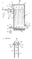
まず、図1を用いて高温ガスの冷却装置について説明する。本発明の高温ガスの冷却装置1は、冷却装置躯体3、トレイ5、給水ノズル7、粒状中和剤入り濾過装置9、濾過装置11、循環ポンプ13および循環水配管15から構成されている。
【0023】
冷却装置躯体3は、外部を鉄板で囲繞するとともに内部に耐火モルタルのような壁体を有する立方体状の構造物で構成され、冷却装置躯体3の上部域には前工程の燃焼装置(図示略)から排出された高温ガス23を導入するためのガス入口部25が設けられている。一方、冷却装置躯体3の下部域には導入された高温ガス23を冷却した後、低温ガス41を排出するためのガス出口部27が設けられている。
【0024】
図1に示すように、冷却装置躯体3の内部には、それぞれ3段階に亘り相互に離間したトレイ5(a、b、c)の最下段に配設された第3段トレイ5cより離間した下方位置に粒状中和剤入り濾過装置9が配設してある。
【0025】
トレイ5は底板35とその底板35を垂直状の堰を成す周辺部材で囲繞するとともに上部が開放された皿状容器とし、この皿状容器には冷却水17が貯留されるようになっている。トレイ5は高温ガス23が効率よく冷却できるように高い熱伝導性を有する材料で加工され、第1段トレイ5aの底板35は伝熱面積を増やし冷却効率を向上するために連続した凹凸部で構成され、残りの第2段トレイ5bと第3段トレイ5cは複数の伝熱フイン33を有した構成となっている。なお、周辺部材は垂直状の堰に限定されるものではなく、冷却水17が貯留されるものであれば、傾斜した堰であってもよい。
【0026】
なお、第1段トレイ5aの底板35の外面部に複数の伝熱フイン33を設けていないのは、第2段トレイ5bと第3段トレイ5cに比べて第1段トレイ5aは輻射伝熱が特に大きいためである。なお、トレイ5や伝熱フイン33などの材料には、不錆鋼を使用した。
【0027】
ガス入口部25を介して導入された高温ガス23は、トレイ5と粒状中和剤入り濾過装置9間でジグザグ状になるように蛇行しつつ冷却されながら通過し、最後にガス出口部27から排出されるするように構成されている。
【0028】
第1段トレイ5aの一端部は冷却装置躯体3の内壁面3bに接するように水平配設され、第1段トレイ5aの他端部と冷却装置躯体3の内壁面3aとの間にガス通路29aを設け、ガス入口部25を介して導入された高温ガス23が第1段トレイ5aの水面19上を通過する際に冷却され、次の第2段トレイ5b側にガス通路29aを介して強制的に流入するようになっている。
【0029】
また第2段トレイ5bは第1段トレイ5aより離間した下方に位置し、この第2段トレイ5bの一端部は冷却装置躯体3の内壁面3aに接するように水平配設され、第2段トレイ5bの他端部と冷却装置躯体3の内壁面3b間にガス通路29bを設け、第1段トレイ5aと第2段トレイ5bの水面19上を通過する際に冷却された後、第3段トレイ5c側にガス通路29bを介して強制的に流入するようになっている。
【0030】
さらに、第3段トレイ5cは第2段トレイ5bより離間した下方に位置し、この第3段トレイ5cの一端部は冷却装置躯体3の内壁面3b側に接するように水平配設され、第3段トレイ5cの他端部と冷却装置躯体3の内壁面3a間にガス通路29cを設け、第2段トレイ5bと第3段トレイ5cの水面19上を通過する際に冷却された後、粒状中和剤入り濾過装置9側にガス通路29cを介して強制的に流入するようになっている。
【0031】
粒状中和剤入り濾過装置9は第3段トレイ5cより離間した下方に位置し、この粒状中和剤入り濾過装置9の一端部は冷却装置躯体3の内壁面3aに開口した開口部30寄りに水平配設されている。粒状中和剤入り濾過装置9の他端部と冷却装置躯体3の内壁面3b間にガス通路29dが設けられ、高温ガス23はガス通路29dを経由して粒状中和剤入り濾過装置9の下方部からガス出口部27に向かう途中、粒状中和剤入り濾過装置9の開口部39から滴下した冷却水17により冷却された後、ガス出口部27から排出されるようになっている。
【0032】
なお、粒状中和剤入り濾過装置9は、ガス中に含有されるSOやHClガスなどの酸性物質が冷却水17に吸収され、その冷却水17中に含有する酸性物質を中和するために設けられた粒状中和剤、例えば石灰石の充填層を形成するための粒状中和剤入り濾過装置9である。
【0033】
粒状中和剤入り濾過装置9の底部には、粒状中和剤が落下しないように一定ピッチに穿設された複数の多孔状の開口部39を有した構成を成している。後述する給水ノズル7から第3段トレイ5cに多量に供給された冷却水17は、周辺部材からオーバーフローして粒状中和剤入り濾過装置9上に流下する。粒状中和剤入り濾過装置9上に流下した冷却水17は、粒状中和剤入り濾過装置9内に充填された粒状中和剤中を通過した後、開口部39から滴下し、ガス冷却が行われる。
【0034】
符合31は蓋体であり、粒状中和剤入り濾過装置9に充填された粒状中和剤上に堆積した捕集ダストにより低下した中和剤の効能を改善するために、粒状中和剤を充填したままの状態で粒状中和剤入り濾過装置9を開口部30を介して冷却装置躯体3の外部に一旦抜き出す際に開放し、洗浄を行って再度効能の改善した粒状中和剤を充填した粒状中和剤入り濾過装置9を装着した後、密閉するのものである。
【0035】
また粒状中和剤入り濾過装置9の下方部の冷却装置躯体3の内壁面3a側には、ガス入口部25から導入されたが高温ガス23がトレイ5と粒状中和剤入り濾過装置9を通過する際に急冷された低温ガス41が排出されるガス出口部27が配設してある。
【0036】
外部から冷却水17を供給するために設けられた給水ノズル7は、第3段トレイ5cより離間した上方に冷却装置躯体3の内壁面3bを挿通して配設され、給水ノズル7の先端部は給水ノズル7から給水された冷却水17が第3段トレイ5cの上部に流下するように内壁面3bから離間した位置に配設されている。符合20は給水を示す。
【0037】
一般的に定常状態下における水バランスでは、給水ノズル7から供給される冷却水17の水量は、トレイ5に貯留された冷却水17と水槽21に貯留された冷却水17が高温ガス23の持つ顕熱によって蒸発し飽和スチームとしてガス出口部27から低温ガス41に同伴し排出される水量に匹敵する分だけ供給すればよいのである。
【0038】
給水ノズル7から第3段トレイ5cに多量の冷却水17が供給され、周辺部材37からオーバーフローした冷却水17は、冷却装置躯体3の底部43に配設された水槽21に貯留される。
【0039】
この水槽21に貯留された冷却水17中には、ガス入口部25に導入された高温ガス23に同伴する煤塵や中和剤生成物などのダストも捕集されている。水槽21の冷却装置躯体3の内壁面3b側には、水槽21に貯留された冷却水17を循環・再使用するための循環水配管15が配設され、冷却水17は、冷却装置躯体3の外部で濾過装置11と循環ポンプ13を経由した後、冷却装置躯体3の内壁面3bを挿通し、第1段トレイ5a上に開口ノズル15aとして位置するように配設されている。
【0040】
またガス入口部25には温度計t1が取り付けられている。この温度計t1の先端部はできるだけ精度良く高温ガス23の温度を測定するためにガス入口部25の内壁面より少し内部に突き出た状態で設けられている。ガス入口部25と同様に、ガス出口部27にもガス出口部27の内壁面より少し内部に突き出た状態で温度計t2が取り付けられている。
【0041】
また冷却装置躯体3の内壁面は耐火モルタルのような熱放射材料で被覆してあり、トレイ5の底板35の外面部は、熱放射率を低下させるとともに熱吸収を効率的に行えるように、黒色化されている。なお符合19はトレイ5に貯留された冷却水17の水面を示す。
【0042】
このように構成された高温ガスの急冷装置1により高温ガス23の冷却は次のようにして行われる。
【0043】
すなわち、
(1)給水ノズル7から第3段トレイ5cに多量の冷却水17が供給され、ガス通路29c側の周辺部からオーバーフローした冷却水17は粒状中和剤入り濾過装置9上に流下する。
(2)粒状中和剤入り濾過装置9上に流下した冷却水17は、充填された粒状中和剤間を通過して開口部39から水槽21に散水状となって流下する。
【0044】
(3)水槽21に一定深さ貯留された冷却水17は、濾過装置11を経由し、予め起動されている循環ポンプ13に導水される。
(4)循環ポンプ13に導水された冷却水17は、循環水配管15を経由して開口ノズル15aから第1段トレイ5aに供給される。
(5)第1段トレイ5aに供給されガス通路29a側の周辺部材からオーバーフローした冷却水17は第2段トレイ5b上に流下する。
【0045】
(6)第2段トレイ5b上に流下した冷却水17は、やがて満杯となってガス通路29b側の第2段トレイ5bの周辺部材からオーバーフローして、第3段トレイ5c上に落下する。
(7)このようにして冷却水17の循環経路が形成されると、前工程の燃焼装置から排出された高温ガス23をガス入口部25から導入する。
【0046】
(8)ガス入口部25から導入された高温ガス23は、第1段トレイ5aの水面19側を通る際に、水面19との接触による伝熱・水の蒸発潜熱によって急冷される。
(9)次いで、ガス通路29aを通った後、第1段トレイ5aと第2段トレイ5bとの間を通過するのである。この時高温ガス23は第1段トレイ5aの凹凸部で構成される底板35の外面部と接触して、高温ガス23の温度は伝熱により低下する。
【0047】
(10)同時に第2段トレイ5bの水面19側を通る際に、水面19との接触による伝熱・水の蒸発潜熱および発生蒸気の混入によって急冷される。
(11)次いで、ガス通路29bを通った後、第2段トレイ5bと第3段トレイ5cとの間を通過するが、この時冷却されつつある高温ガス23は伝熱フイン33と接触して、伝熱により温度はさらに低下する。
【0048】
(12)この後、ガス通路29cを通った後、第2段トレイ5bと第3段トレイ5cと同様に第3段トレイ5cと粒状中和剤入り濾過装置9との間を冷却されながら通過する。
(13)ガス通路29dを経由した高温ガス23は、ガス出口部27に向かう時、粒状中和剤入り濾過装置9の開口部39から流下する冷却水17により十字流となって冷却された後、ガス出口部27から排出される。なおガス入口部25から導入された高温ガス23は途中冷却されガス出口部27から排出されるが、この時の冷却水17と高温ガス23との流れは並流であり、高温ガス23の冷却には大きな効果を奏する。
(14)定常運転に移行した後は、トレイ5の循環量を蒸発冷却に必要な理論量の1〜10重量倍に維持するように運転を行う。
【0049】
具体的な実施例について説明する。
〔実施例1〕
図1に示す高温ガスの冷却装置1を用いて実験を行い、次のような実験結果を得た。
まず、高温ガスの冷却装置1の内有効寸法は、幅400×奥行き1200×高さ1800mmであり、小型焼却炉(建築廃木材供給量100kg/h,排ガス量1000Nm/h、高温ガス23の温度は900℃)に接続して実験した。その結果、冷却水17の循環量を10倍とした場合、冷却後のガス出口部27の低温ガス41の温度は110℃となった。
【0050】
また循環量を1倍とした場合、冷却後のガス出口部27の低温ガス41の温度は140℃であった。この時、平均のガス滞留時間は、1.1秒であった。この場合の水面19の見掛けの熱流束Q(熱の移動量W÷見掛け伝熱面積m)を推算すると、最大値で約9万KW/m(≒8万Kcal/mh)に達しており、沸騰伝熱域の熱流束であることがわかった。
【0051】
本実験では、水面19で高い熱流束が達成できる遷移沸騰域にして急冷を行うことができた。
【0052】
なお、第1段トレイ5a中に高温ガス23中に含有される酸性ガス(例えばSO2やHClガスなど)と反応してこれらの酸性ガスを除去するために中和剤として粒径範囲が1〜5mmの石灰石を入れ、粒状中和剤入れ濾過装置9にセルローズ系の濾過材を入れて実験した。その結果、循環量を10倍にした場合、循環する冷却水17の水素イオン濃度は、約pH8に維持できた。
【0053】
なお実験の結果、水面19自体は、蒸発潜熱による冷却効果で温度が急激に降下するので、この水面19の温度を沸騰点ないしはその近くに維持しながら、高い熱流束が得られ、この結果、ダイオキシン類の再合成を確実に防止することができた。
【0054】
図2は本発明における垂直に釣り下げた冷却パネルの両面に交互に冷却水を流下させるようにした高温ガスの冷却装置の縦断面図である。ここで、冷却パネルは、平板又は凹凸をつけたプレートであっても良い。
【0055】
まず、図2(1)と図2(2)を用いて高温ガスの冷却装置について説明する。本発明の高温ガスの冷却装置50は、冷却装置躯体52、冷却パネル54、パネル右側の冷却水噴出管56、パネル左側の冷却水噴出管58および乾燥排出機70から構成されている。
【0056】
冷却装置躯体52は、外部を鉄板で囲繞するとともに内部に耐火モルタルのような壁体を有する立方体状の構造物で構成され、冷却装置躯体52の上部域には前工程の燃焼装置(図示略)から排出された高温ガス66を導入するためのガス入口部62が設けられている。一方、冷却装置躯体52の下部域には導入された高温ガス66を冷却した後、低温ガス68を排出するためのガス出口部64が設けられている。
【0057】
図2(1)に示すように、冷却装置躯体52の内部空間部を複数の冷却パネル54(本実施例では、6枚)で略等間隔になるように冷却パネル54の上端部に固着されたリング状の吊り下げ部60を直胴棒(図示略)に挿通した状態で等間隔かつ垂直方向に吊り下げた状態で取り付けられている。
【0058】
冷却パネル54の長さは、冷却パネル54の上端部がガス入口部62の直下近傍にあり、他方冷却パネル54の下端部がガス出口部64の直上近傍に位置するように構成されている。
【0059】
冷却装置躯体52の内部の下部域には、乾燥排出機70が傾斜した状態で配設してある。乾燥排出機70の一端部はガス出口部64の直下近傍に位置させ、他端部は冷却装置躯体52の挿通後、反ガス出口部64側に向かって上昇する傾斜角を有した状態で配設してある。
【0060】
冷却装置躯体52の下部に配設された乾燥排出機70の上面側は開放されており、この開放された部分に捕集された煤塵などの捕集ダスト74が堆積した後、スクリューフライト80aを一定ピッチとなるように螺旋状に固着されたスクリュ軸80を回動させることにより、捕集ダスト74が乾燥排出機70の端部域に配設された排出ノズル72から外部に取り出せるようになっている。
【0061】
また図2(2)に示すように、冷却パネル54に向かって冷却水噴出ノズル56a、58aから噴射される冷却水53が冷却パネル54の片面づつを交互に冷却するようになっている。冷却水噴出管56、58は、(1)に示すように冷却装置躯体52の外部に配設された冷却水噴出用配管76、78から冷却装置躯体52を挿通して冷却パネル54から離間した左右側に配設されている。
【0062】
この冷却水噴出ノズル56a、58aは、冷却水噴出管56、58の先端部に冷却水噴出管56、58の軸心と直交する方向に固着されるとともに、冷却パネル54から離間した左右側に配設してあり、その先端部は冷却パネル54の斜め上方から冷却パネル54の表面に向かって交互に冷却水53を噴出するようになっている。
【0063】
またガス入口部62には温度計t1が取り付けられている。この温度計t1の先端部はできるだけ精度良く高温ガス66の温度を測定するためにガス入口部62の内壁面より少し内部に突き出た状態で設けられている。ガス入口部62と同様に、ガス出口部64にもガス出口部64の内壁面より少し内部に突き出た状態で温度計t2が取り付けられている。また符合82はタイマ付き弁、84は温度調節機構、86は給水を示す。
【0064】
このように構成された高温ガスの急冷装置50を用いた高温ガス66の冷却は次のようにして行われる。
【0065】
すなわち、
(1)まず冷却水噴出用配管76、78から冷却噴出管56、58を経由して冷却水噴出ノズル56aから冷却パネル54に向かって冷却水53を噴出させて片濡れ壁を形成しておく。
(2)次に、前工程の燃焼装置から排出された高温ガス66をガス入口部62から導入すると同時にスクリュ軸80を駆動させておく。
【0066】
(3)ガス入口部62から導入された高温ガス66は、複数の冷却パネル54間を通る際に、冷却パネル54上を流下する冷却水53との接触による伝熱・水の蒸発潜熱および発生蒸気の混入によって急冷される。
【0067】
(4)同時に高温ガス66の顕熱によって冷却パネル54上を流下する冷却水53は蒸発消滅してしまう。このため、冷却水53が蒸発消滅した後は、煤塵や中和剤生成物などの捕集ダスト74は冷却装置躯体52の下部に配設された乾燥排出機70上に堆積する。
【0068】
(5)次いで、一定時間経過するとタイマ付き弁82が作動し、冷却水噴出ノズル56aから冷却パネル54に向かって噴出している冷却水53を停止するとともに、新たに冷却水噴出ノズル58aから冷却パネル54に向かって冷却水53を噴出させて片濡れ壁を形成する。このように冷却パネル54に向かって交互に冷却水53を噴出させることにより、高温ガス66の顕熱は片濡れ壁冷却効果によって急冷する。
【0069】
(6)冷却パネル54に捕集される煤塵や中和剤生成物などの捕集ダスト74を除去するために、冷却水53をパルス的に噴出して洗い落とす操作を行う。集塵ダスト74は上部が開放された乾燥搬送機70の上に落下し、スクリュ軸80の回動によりスクリューフライト80aを介してから排出ノズル72から系外に取り出される。
(7)なお定常運転中は、ガス出口部64から排出される低温ガス68の温度を一定に保つように給水86を温度調節機構84で調節する。
【0070】
具体的な実施例について説明する。
〔実施例2〕
図2に示す高温ガスの冷却装置50を用いて実験を行い、次のような実験結果を得た。
まず、高温ガスの冷却装置50の内有効寸法は、幅400×奥行き900×高さ1800mmであり、小型焼却炉(建築廃木材供給量100kg/h,排ガス量1000Nm/h、高温ガス66の温度は900℃)に接続して実験した。
【0071】
実験は、前述した実施例1とほぼ同一の条件で行った。この時、温度調節機構84を150℃に設定して、高温ガス66の量を±50容積%変化させたところ、低温ガス68の温度変動は150±5℃であった。この時の平均のガス滞留時間は、計算の結果、0.84秒となった。
【0072】
次に、図3は図1の水平トレイと傾斜パネルとを組み合わせた場合の高温ガスの冷却装置の縦断面図である。
【0073】
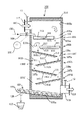
まず、図3を用いて高温ガスの冷却装置について説明する。本発明の高温ガスの冷却装置100は、冷却装置躯体103、水平トレイ105、傾斜パネル107、給水ノズル109および乾燥排出機123から構成されている。
【0074】
冷却装置躯体103は、外部を鉄板で囲繞するとともに内部に耐火モルタルのような壁体を有する立方体状の構造物で構成され、冷却装置躯体103の上部域には前工程の燃焼装置(図示略)から排出された高温ガス115を導入するためのガス入口部117が設けられている。一方、冷却装置躯体103の下部域には導入された高温ガス115を冷却した後、低温ガス121を排出するためのガス出口部119が設けられている。
【0075】
図3に示すように、冷却装置躯体103の内部には、水平トレイ105と傾斜パネル107が組み合わせて配設してある。すなわち、水平トレイ105は冷却装置躯体103の上部域に2段階に亘り相互に離間した第1段水平トレイ105aと第2段水平トレイ105bで構成され、また傾斜パネル107は水平トレイ105の下部域に4段階に亘り相互に離間した第1段傾斜パネル107a、第2段傾斜パネル107b、第3段傾斜パネル107cおよび第4段傾斜パネル107dで構成されている。
【0076】
まず、水平トレイ105について説明する。水平トレイ105は底板135とその底板135を垂直状の堰を成す周辺部材で囲繞するとともに上部が開放された皿状容器とし、この皿状容器には冷却水111が貯留されるようになっている。水平トレイ105は高温ガス115が効率よく冷却できるように高い熱伝導性を有する材料で加工され、伝熱面積を増やし冷却効率を向上するために、第1段水平トレイ105aの底板135の外面部は連続した凹凸部で構成されている。また、残りの第2段水平トレイ105bは複数の伝熱フイン133を有した構成となっている。なお、第1段水平トレイ105aの底板135の外面部に複数の伝熱フイン133が設けられていないのは、第2段水平トレイ105bに比べて第1段水平トレイ105aの方は輻射伝熱が特に大きいためである。また、水平トレイ105や伝熱フイン133などの材料には、不錆鋼を使用した。なお、周辺部材は垂直状の堰に限定するものではなく、冷却水111が貯留されるものであれば傾斜した堰であってもよい。
【0077】
ガス入口部117を介して導入された高温ガス115は、水平トレイ105(a、b)および傾斜パネル107(a、b、c、d)と冷却装置躯体103の内壁面103(a、b)との間をジグザグ状になるように蛇行しつつ冷却されながら通過し、最後にガス出口部119から排出されるするように構成されている。
【0078】
第1段水平トレイ105aの一端部は冷却装置躯体103の内壁面103bに接するように水平配設され、第1段水平トレイ105aの他端部と冷却装置躯体103の内壁面103a間にガス通路139aが設けられており、ガス入口部117を介して導入された高温ガス115は第1段水平トレイ105aの水面113上を通過する間に冷却された後、次の第2段水平トレイ105b側にガス通路139aを介して強制的に流入するようになっている。
【0079】
また第2段水平トレイ105bは第1段水平トレイ105aより離間した下方に位置し、この第2段水平トレイ105bの一端部は冷却装置躯体103の内壁面103aに接するように水平配設されている。第2段水平トレイ105bの他端部と冷却装置躯体103の内壁面103b間にガス通路139bが設けられており、第1段水平トレイ105aの底板135と第2段水平トレイ105bの水面113間を通過する時に冷却された後、第1段傾斜パネル107a側にガス通路139bを経由して強制的に流入するようになっている。
【0080】
次に、傾斜パネル107について説明する。傾斜パネル107は冷却水111が傾斜した冷却パネルを流下するようになっている。傾斜パネル107は高温ガス115が効率よく冷却できるように高い熱伝導性を有する材料で加工され、その内外面には伝熱面積を増やし冷却効率を向上するために、第1段傾斜パネル107aから第4段傾斜パネル107dまでの冷却パネル143の外面側は複数の伝熱フイン141(a、b、c、d)を有した構成となっている。なお、水平トレイ105や傾斜パネル107および伝熱フイン133、141などの材料には、不錆鋼を使用した。
【0081】
まず、第1段傾斜パネル107aは第2段水平トレイ105bより離間した下方に位置し、図3の正面から見て右下に傾斜した状態で固着されている。この第1段傾斜パネル107aの一端部は冷却装置躯体103の内壁面103b側に接するように配設され、第1段傾斜パネル107aの他端部と冷却装置躯体103の内壁面103a間にガス通路139cを設け、高温ガス115は第2段水平トレイ105bの底部と第1段傾斜パネル107aの水面113上を通過する時に冷却された後、ガス通路139cを経由して第2段傾斜パネル107b側に強制的に流入するようになっている。
【0082】
以下、第1段傾斜パネル107aと第2段傾斜パネル107bと同様に冷却装置躯体103の内壁面103a、103b側に交互に接するように第3段傾斜パネル107cと第4段傾斜パネル107dが配設され、第2段傾斜パネル107bの他端部と冷却装置躯体103の内壁面103b間にガス通路139dを設け、第3段傾斜パネル107cの他端部と冷却装置躯体103の内壁面103a間にガス通路139eを設け、さらに第4段傾斜パネル107dの他端部と冷却装置躯体103の内壁面103b間にガス通路139fを有する構成となっており、各パネル107を通過する時、排出ガスは強制的に冷却された後、ガス出口部119から排出されるようになっている。なお、第3段傾斜パネル107cも第1段傾斜パネル107aと同様に図3の正面から見て右下に傾斜した状態で固着され、さらに第2段傾斜パネル107bと第4段傾斜パネル107dは図3の正面から見て左下に傾斜した状態で固着されている
【0083】
外部から冷却水111を供給するために設けられた給水ノズル109は、第1段水平トレイ105aより離間した上方に冷却装置躯体103の内壁面103bを挿通して配設され、給水ノズル109の先端部は給水ノズル109から供給された冷却水111が第1段水平トレイ105a上に落下するように内壁面103bから離間した位置に突設した状態で配設されている。
【0084】
給水ノズル109から供給される冷却水111の水量は、水平トレイ105(a、b)を経由して片濡れ壁の現象を呈する傾斜パネル107(a、b、c、d)上を流下する時に高温ガス115の持つ顕熱によって蒸発してしまうような水量に匹敵する分だけ供給するのである。
【0085】
冷却装置躯体103の内部の下部域には、乾燥排出機123が傾斜した状態で配設してある。乾燥排出機123の一端部はガス出口部119の直下近傍に位置し、他端部は冷却装置躯体103を挿通後、反ガス出口部121側に向かって上昇する傾斜角を有する構成をなす。
【0086】
冷却装置躯体103の下部に配設された乾燥排出機123の上面側は開放されており、この開放された部分に捕集された煤塵などの捕集ダスト127が堆積した後、フライト129aを一定ピッチとなるように螺旋状に固着されたスクリュ軸129を回動させることにより、捕集ダスト127が乾燥排出機123の端部域に配設された排出ノズル125から外部に取り出せるようになっている。
【0087】
またガス入口部117には温度計t1が取り付けられている。この温度計t1の先端部はできるだけ精度良く高温ガス115の温度を測定するためにガス入口部117の内壁面より少し内部に突き出た状態で設けられている。ガス入口部117と同様に、ガス出口部119にもガス出口部119の内壁面より少し内部に突き出た状態で温度計t2が取り付けられている。
【0088】
また冷却装置躯体103の内壁面は耐火モルタルのような熱放射材料で被覆するとともに、水平トレイ105の底板135と傾斜パネル107の冷却パネル143の外面部は、熱放射率を低下させ、かつ熱吸収を効率的に行えるように、黒色化されている。なお符合113は水平トレイ105に貯留された冷却水111の水面、132は給水を示す。
【0089】
このように構成された高温ガスの冷却装置100を用いた高温ガス115の冷却は次のようにして行われる。
【0090】
すなわち、高温ガス115を高温ガスの急冷装置100に導入する前に次のようなことを行う。
(1)給水ノズル109から第1段水平トレイ105aに多量の冷却水111が供給され、周辺部材からオーバーフローした冷却水111は、第2段水平トレイ105b上に流下する。
【0091】
(2)同様に第2段水平トレイ105bから第1傾斜パネル107aへオーバーフローによって流下し、以下冷却水111は第1傾斜パネル107aから第4傾斜パネル107dまでを経由して逐次流下させておく。この時、乾燥排出機123のスクリュ軸129も回動させておく。
(3)次に、前工程の燃焼装置から排出された高温ガス115をガス入口部117から導入する。
【0092】
(3)ガス入口部117から導入された高温ガス115は、第1段水平トレイ105aの水面113上を通る際に、水面113との接触による伝熱・水の蒸発潜熱によって急冷される。
(4)次いで、ガス通路139aを通った後、第1段水平トレイ105aと第2段水平トレイ105bとの間を通る。この時高温ガス115は第1段水平トレイ105aの凹凸部で構成される底板135の外面部と接触して、高温ガス115の温度は伝熱により低下する。
【0093】
(5)同時に第2段水平トレイ105bの水面113上を通る際に、水面113との接触による伝熱・水の蒸発潜熱および発生蒸気の混入によって急冷される。
(6)次いで、ガス通路139bを通った後、第2段水平トレイ105bと第1段傾斜パネル107aとの間を通る。この時高温ガス115は伝熱フイン133と第1段傾斜パネル107aを流下する冷却水111に接触して、伝熱により温度はさらに低下する。
【0094】
(7)この後、ガス通路139cを通った後、第1段傾斜パネル107aと第2段傾斜パネル107b間を経由してガス通路139dを通るのである。同様に、ガス通路139eからガス通路139feを経由した後、ガス出口部119から排出される。
【0095】
(8)給水ノズル109から供給される冷却水111の水量は、水平トレイ105(a、b)を経由して片濡れ壁の現象を呈する傾斜パネル107(a、b、c、d)上を流下する時に高温ガス115の持つ顕熱によって蒸発してしまうような水量に匹敵する分だけ供給するのである。この時の冷却水111と高温ガス115との流れは並流であり、高温ガス115の冷却に大きな効果を奏する。
【0096】
(9)同時に、高温ガス115の顕熱によって第1段傾斜パネル107aから第4段傾斜パネル107dまでを流下する冷却水111は途中蒸発消滅してしまう。冷却水111が蒸発消滅した後は、第1段傾斜パネル107aから第4段傾斜パネル107d間に堆積した捕集ダスト127などを洗い落とすために、時々給水ノズル109から冷却水111をパルス的に増量させる操作を行うのである。
【0097】
(10)冷却水111をパルス的に増量させた場合は、冷却水111と一緒に捕集ダスト127が、冷却装置躯体103の下部に配設された乾燥排出機123上に落下し堆積する。この後、パルス的に増量した時に捕集ダスト127と一緒に流下した冷却水111は、増量しない通常の操作に戻した時の高温ガス115の顕熱で乾燥してしまうため、乾燥排出機123の排出ノズル125から排出されるのは捕集ダスト127だけとなる。なお定常運転中は、ガス出口部119から排出される低温ガス121の温度を一定に保つように給水132量を温度調節機構131で調節する。
【0098】
具体的な実施例について説明する。
〔実施例3〕
図3に示す高温ガスの冷却装置100を用いて実験を行い、次のような実験結果を得た。
まず、高温ガスの冷却装置100の内有効寸法は、幅400×奥行き1200×高さ1800mmであり、小型焼却炉(建築廃木材供給量100kg/h,排ガス量1000Nm/h、高温ガス115の温度は900℃)に接続して実験した。
【0099】
実験は、前述した実施例1とほぼ同一の条件で行った。この時、温度調節機構131を150℃に設定して、高温ガス115の排出量を±50容積%変化させたところ、低温ガス121の温度変動は150±5℃であった。この時の平均ガス滞留時間は、計算の結果、1.1秒となった。
【0100】
なお、実験中は、水平トレイ105(a、b)上の凹部に中和剤として粒径範囲が1〜5mmの石灰石を充填使用した。また、これら傾斜パネル107(a、b、c、d)に捕集される煤塵や中和剤生成物などの捕集ダスト127は、時折、給水ノズル109から冷却水111をパルス的に増量して洗い落とす操作を行なった。
【0101】
図4は本発明におけるガス流路と蒸留塔方式のトレイとを組合せた高温ガスの冷却装置の縦断面図である。
【0102】
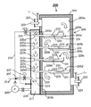
まず、図4を用いて高温ガスの冷却装置について説明する。本発明の高温ガスの冷却装置150は、冷却装置躯体153、共有トレイ155、隔壁157、濾過装置158、循環ポンプ160、循環水配管161、給水ノズル162、循環水ノズル163、ガスバイパス通路164、ガス通路178、溢流管180および温度調節機構190から構成されている。
【0103】
冷却装置躯体153は、外部を鉄板で囲繞するとともに内部に耐火モルタルのような壁体を有する立方体状の構造物で構成され、冷却装置躯体153の上部域には前工程の燃焼装置(図示略)から排出された高温ガス172を導入するためのガス入口部174が設けられている。一方、隔壁157によって冷却装置躯体153内部を左右に分離するとともに、隔壁157に対してガス入口部174と対向する冷却装置躯体153の上部域には冷却した低温ガス182を排出するためのガス出口部176が設けられている。ガス入口部174に導入された下向き流れの高温ガス172をジグザグ状に設けられたガス通路178(a、b、c、d)に通すとともに、溢流管180(a、b)内を流下する冷却水166と並流方向に流しながら冷却した後、最下段の第4段共有トレイ155dの下部側を経由し、上向き流れとなった高温ガス172をジグザグ状に設けられたガス通路178(e、f、g、h)に通すとともに、溢流管180(c、d)内を流下する冷却水166と向流方向に流しながら冷却しガス出口部176から低温ガス182を排出するようになっている。
【0104】
図4に示すように、4段階に亘り相互に離間した共有トレイ155(a、b、c、d)が配設されている。共有トレイ155は底板184とその底板184を垂直状の堰を成す周辺部材で囲繞するとともに上部が開放された皿状容器とし、この皿状容器には冷却水166が貯留されるようになっている。共有トレイ155は高温ガス172が効率よく冷却できるように高い熱伝導性を有する材料で加工され、その外面には伝熱面積を増やし冷却効率を向上するために、複数の伝熱フイン188(a、b、c、d、e、f、g)を有した構成となっている。共有トレイ155や伝熱フイン188の材料には、不錆鋼を使用した。なお、周辺部材は垂直状の堰に限定するものではなく、冷却水166が貯留されるものであれば、傾斜した堰であってもよい。
【0105】
共有トレイ155は冷却装置躯体153の内壁面153aと153bの両方に接するように配設されている。冷却装置躯体153の内部を2分割するように中央部に隔壁157が分設されている。これら分設された隔壁157(a、b、c、d)は、上端部をガスが挿通しないように各共有トレイ155と対向する上部位置に配設された部材に固着されると同時に、下端部を共有トレイ155に貯留した冷却水166中に浸漬し、ガスを導通しないように液封されている。
【0106】
ここで隔壁157について詳述すると、隔壁157は第1隔壁157aから第4隔壁157dの4つに分設されている。まず、第1隔壁157aは、内壁153cに一端部を固着し、他端部を第1段共有トレイ155aに貯留された冷却水166中に浸漬し液封されている。また、第2隔壁157bは、第1段共有トレイ155aの底板184に一端部を固着し、他端部を第2段共有トレイ155bに貯留された冷却水中に浸漬し液封されている。
【0107】
同様に第3隔壁157cは、第2段共有トレイ155bの底板184に一端部を固着し、他端部を第3段共有トレイ155cに貯留された冷却水中に浸漬し液封されている。また、第4隔壁157dは、第3段共有トレイ155cの底板184に一端部を固着し、他端部を第4段共有トレイ155dに貯留された冷却水中に浸漬し液封されている。
【0108】
隔壁157を中心として共有トレイ155の左右対称となる位置にガス通路178(a、b、c、d、e、f、g、h)が設けられている。このガス通路178の上端部は周辺部材の上端部とほぼ同一の高さに設定され、下端部は共有トレイ155の底板184と面一となるように底板184に固着されてる。ガス通路178は、ガス入口部174を介して導入された高温ガス172が、蛇行しつつガス通路178を通過する間に冷却され、最後にガス出口部176から低温ガス182として排出されるするようにジグザグ状に配設されている。
【0109】
各段の共有トレイ155には、循環水167のもととなる冷却水166がオーバーフローしないように溢流管180(a、b、c、d)が配設してある。この溢流管180の上端部は、ガス通路178の上端部と周辺部の上端部より若干低くなるように設定され、下端部は必ず冷却水166中に浸漬する長さに設定した後、共有トレイ155の冷却装置躯体153の内壁面153aまたは153b側近傍に固着されている。
【0110】
外部から冷却水166を供給するために設けられた給水ノズル162は、第2段共有トレイ155bより離間した上方に冷却装置躯体153の内壁面153bを挿通して配設され、その先端部は給水ノズル162から給水された冷却水166が第2段共有トレイ155bの上部に流下するように内壁面153bから離間した位置に配設されている。
【0111】
一般的に定常状態下における水バランスでは、給水ノズル162から供給される冷却水166の水量は、共有トレイ155に貯留された冷却水166と水槽170に貯留された冷却水166が高温ガス172の持つ顕熱によって蒸発し飽和スチームとしてガス出口部176から低温ガス182に同伴し排出される水量に匹敵する分だけ供給するのである。
【0112】
給水ノズル162から第2段共有トレイ155bに多量の冷却水166が供給される。冷却水166が第2段共有トレイ155b中に満杯になると、溢流管180aからオーバーフローした冷却水166は第3段共有トレイ155cに流下し、貯留される。さらに、溢流管180cからオーバーフローした冷却水166は第4段共有トレイ155dに流下し、貯留される。引き続き、溢流管180bからオーバーフローした冷却水166は水槽170に流下し、冷却装置躯体153の底部に配設された水槽170に一定の水深となるように貯留される。
【0113】
この水槽170に貯留された冷却水166中には、ガス入口部174に導入された高温ガス172に同伴する煤塵なども含有される。水槽170の側面には、水槽170に貯留された冷却水166を循環・再使用するための循環水配管161の一方端部が配設され、循環水配管161の他方端部は冷却装置躯体153の外部を迂回しており、冷却水166中に含有する煤塵などを濾過する濾過装置158と循環ポンプ160を経由し、第1段共有トレイ155aの上部域の冷却装置躯体153の内壁面153bを挿通した後、第1段共有トレイ155a上の開口ノズル163に循環するように配設されている。
【0114】
またガス入口部174には温度計t1が取り付けられている。この温度計t1の先端部はできるだけ精度良く高温ガス172の温度を測定するためにガス入口部174の内壁面より少し内部に突き出た状態で設けられている。ガス入口部174と同様に、ガス出口部176にもガス出口部176の内壁面より少し内部に突き出た状態で温度計t2が取り付けられている。
【0115】
冷却装置躯体153の内壁面は耐火モルタルのような熱放射材料で被覆するとともに、共有トレイ155と伝熱フイン188は、熱放射率を低下させ、かつ熱吸収を効率的に行えるように、黒色化されている。なお符合168は共有トレイ155と水槽170に貯留された冷却水166の水面、169は給水を示す。
【0116】
このように構成された高温ガスの冷却装置150を用いた高温ガス172の冷却は次のようにして行われる。
【0117】
すなわち、
(1)まず、給水ノズル162から第2段共有トレイ155bに多量の冷却水166が供給され、オーバーフローした冷却水166は、溢流管180(a、b、c)を介して第3段共有トレイ155c、第4段共有トレイ155dへと流下して、最後は水槽170に貯留される。
【0118】
(2)水槽170に一定深さ貯留された冷却水166は、濾過装置158を経由し、予め起動してある循環ポンプ160に導水される。
(3)循環ポンプ160に導水された冷却水166は、循環水配管161を経由して開口ノズル163から第1段共有トレイ155aに循環供給される。
【0119】
(4)第1段共有トレイ155aに供給された冷却水166の役目をなす循環水167は溢流管180dを介してオーバーフローし、第2段共有トレイ155bに流下する。
【0120】
(5)第2段共有トレイ155bに流下した冷却水166は、やがて満杯となって溢流管180aからオーバーフローして、第3段共有トレイ155cに流下する。引き続き、第3段共有トレイ155c上に流下した冷却水166は、やがて満杯となって溢流管180cからオーバーフローして、第4段共有トレイ155d上に流下する。
(6)最後は、第4段共有トレイ155d上に流下した冷却水166は、やがて満杯となって溢流管180bからオーバーフローして、水槽170に流下し一定の水深になるまで貯留される。
(7)このようにして冷却水166の循環経路が形成されると、前工程の燃焼装置から排出された高温ガス172をガス入口部174から導入する。
【0121】
(8)ガス入口部174から導入された高温ガス172は、第1段共有トレイ155aに貯留された冷却水166の水面168上を通る際に、水面168との接触による伝熱・水の蒸発潜熱によって急冷される。
(9)次いで、ガス通路178aを通った後、第1段共有トレイ155aと第2段共有トレイ155bとの間を通る。この時高温ガス172は第1段共有トレイ155aの底板184の外面部および複数の伝熱フイン188aと接触して、高温ガス172の温度は伝熱により低下する。
【0122】
(10)同時に第2段共有トレイ155bに貯留されている水面168上を通ることとなり、水面168との接触による伝熱・水の蒸発潜熱および発生蒸気の混入によって急冷され、温度はさらに低下する。
(11)以下前述したことと同様に、引き続き高温ガス172はガス通路178b〜ガス通路178hを経由する間に冷却された後、最後はガス出口部176から低温ガス182として排出される。
(12)定常運転に移行した場合、共有トレイ155の循環量を蒸発冷却に必要な理論量の1〜10重量倍に維持するように運転を行う。
【0123】
(13)なお、ガス入口部174から導入した高温ガス172の一部を冷却済みのガスと混入したい場合は、温度計t3が予め決められた温度となるように、ガスバイパス通路164に設けたバイパス弁165を開放して温度調整を行うとよい。
【0124】
具体的な実施例について説明する。
〔実施例4〕
図4に示す高温ガスの冷却装置150を用いて実験を行い、次のような実験結果を得た。まず、高温ガスの冷却装置150の内有効寸法は、幅600×奥行き1200×高さ1800mmであり、小型焼却炉(建築廃木材供給量100kg/h,排ガス量1000Nm/h、高温ガス172の温度は900℃)に接続して実験した。
【0125】
実験では、温度調節機構190を180℃に設定して、高温ガス172の排出量を±50容積%変化させた以外は、基本的には前述した実施例1とほぼ同一の条件であり、この時の低温ガス182の温度変動は180±4℃であった。また平均ガス滞留時間は、1.6秒と推定された。
【0126】
なお、実験中は、共有トレイ155の中に中和剤として粒径範囲が1〜5mmの石灰石を充填使用した。
【0127】
図5は本発明におけるオーバーフローした冷却水を逐次的に各段のトレイに供給するようにした場合の高温ガスの冷却装置の縦断面図である。
【0128】
まず、図5を用いて高温ガスの冷却装置について説明する。本発明の高温ガスの冷却装置200は、冷却装置躯体203、トレイ205、給水ノズル207、循環ポンプ209、循環水配管212、循環水用導入管225、上戸型ホッパ227、水位調節機構237および補助室239から構成されている。
【0129】
冷却装置躯体203は、外部を鉄板で囲繞するとともに内部に耐火モルタルのような壁体を有する立方体状の構造物で構成され、冷却装置躯体203の上部域には前工程の燃焼装置(図示略)から排出された高温ガス219を導入するためのガス入口部221が設けられている。一方、冷却装置躯体203の下部域には導入された高温ガス219を冷却した後、低温ガス220を排出するためのガス出口部223が設けられている。
【0130】
図5に示すように、冷却装置躯体203の内部には、それぞれ4段階に亘り相互に離間したトレイ205(a、b、c、d)が配設してある。
【0131】
各トレイ205は底板233とその底板233と垂直状の堰を成す周辺部材で囲繞するとともに上部が開放された皿状容器とし、この皿状容器には冷却水213が貯留されるようになっている。トレイ205は高温ガス219が効率よく冷却できるように高い熱伝導性を有する材料で加工され、底板233の外面には伝熱面積を増やし冷却効率を向上するために、複数の伝熱フイン231を有した構成となっている。トレイ205や伝熱フイン231などの材料には、不錆鋼を使用した。なお、周辺部材は垂直状の堰に限定するものではなく、冷却水213が貯留されるものであれば、傾斜した堰であってもよい。
【0132】
ガス入口部221を介して導入された高温ガス219は、各トレイ205(a、b、c、d)と冷却装置躯体203の内壁面との間に配設されたガス通路229(a、b、c、d)をジグザグ状になるように蛇行し冷却されながら通過し、最後にガス出口部223から排出されるするように構成されている。
【0133】
第1段トレイ205aの一端部は冷却装置躯体203の内壁面203bに接するように水平に配設され、第1段トレイ205aの他端部と冷却装置躯体203の内壁面203a間にガス通路229aを設け、ガス入口部221を介して導入された高温ガス219が第1段トレイ205aに貯留された冷却水213の水面215上を通過する際に冷却され、次の第2段トレイ205b側にガス通路229aを介して強制的に流入するようになっている。
【0134】
また第2段トレイ205bは第1段トレイ205aより離間した下方に位置し、この第2段トレイ205bの一端部は冷却装置躯体203の内壁面203aに接するように水平に配設され、第2段トレイ205bの他端部と冷却装置躯体203の内壁面203b間にガス通路229bを設け、第1段トレイ205aの底板233と第2段トレイ205bの水面215上を通過する際に冷却された後、第3段トレイ205c側にガス通路229bを介して強制的に流入するようになっている。なお、以下、第3段トレイ205cと第4段トレイ205dは、前述した第1段トレイ205aおよび第2段トレイ205bと同一構成であるため、ここでは構成の説明を省略する。
【0135】
符合239は補助枠であり、冷却装置躯体203の内壁面203b側の外周端面部に配設されており、ガス入口部221の直下から同一側面側の底部間で立体状の閉空間部を形成している。
【0136】
外部から冷却水213を給水するために設けられた給水ノズル207は、補助室239を挿通して定常状態下における水槽217の水面215より少し上方位置となるように配設され、給水ノズル207の先端部は給水ノズル207から給水された冷却水213が水槽217の上部に流下するように補助室239の内壁面から離間した位置に配設されている。この給水ノズル207には、水位調節機構237が配設してあり、水槽217の水位が常に一定になるように給水量を調節するようになっている。
【0137】
補助枠239の外側面には、水槽217に貯留された冷却水213を循環・再使用するための循環水配管212の一方端部が配設され、循環水配管212の他方端部は、補助枠239の外側面部を迂回し循環ポンプ209を経由した後、補助枠239の上部域に開口ノズル211が位置するように配設されている。
【0138】
この開口ノズル211には先端部近傍に下向きの開口部216が開口されている。一方、第1段トレイ205aの底板233の一部を共有した状態で補助枠239の略中央部まで延在する密閉状の循環水用導入管225aが冷却装置躯体203の内壁面203bを挿通して設けられている。なお、第2段トレイ205bから第4段トレイ205dまで第1段トレイ205aと同一の構成をなす循環水用導入管225(b、c、d)が設けられている。
【0139】
この循環水用導入管225aには、開口ノズル211と離間した対向位置に受水口241aが設けられており、開口ノズル211から流下した冷却水213を受水可能としている。この受水口241aの高さ位置は、第1段トレイ205aの周辺部材の上端部より低くなるように構成されており、第1段トレイ205aに貯留された冷却水213が周辺部からオーバーフローする前に循環水用導入管225aの受水口241aからオーバーフローするようになっている。なお、第2段トレイ205bから第4段トレイ205dまで第1段トレイ205aと同一の構成をなす受水口241(b、c、d)が設けられている。
【0140】
第2段トレイ205bから第4段トレイ205dまでは、受水口241(b、c、d)の直上の離間した位置に上戸型ホッパ227(a、b、c)が配設してある。この上戸型ホッパ227(a、b、c)は、受水口241aからオーバーフローして流下した循環水210のもととなる冷却水213をそれぞれ受水して各々の受水口241(b、c、d)に導水するためのものである。最後に受水口241dからオーバーフローした冷却水213は、水槽217に流下し一定の水深になるまで貯留されるようになっている。
【0141】
またガス入口部221には温度計t1が取り付けられている。この温度計t1の先端部はできるだけ精度良く高温ガス219の温度を測定するためにガス入口部221の内壁面より少し内部に突き出た状態で取り付けられている。ガス入口部221と同様に、ガス出口部223にもガス出口部223の内壁面より少し内部に突き出た状態で温度計t2が取り付けられている。
【0142】
また冷却装置躯体203の全内壁面部は耐火モルタルのような熱放射材料で被覆するとともに、トレイ205の底板233の外面部は、熱放射率を低下させ、かつ熱吸収を効率的に行えるように、黒色化されている。なお符合215はトレイ205に貯留された冷却水の水面、214は給水を示す。
【0143】
このように構成された高温ガスの冷却装置200を用いた高温ガス219の冷却は次のようにして行われる。
【0144】
すなわち、
(1)給水ノズル207から水槽217に多量の冷却水213が供給される。水槽217に一定の深さに貯留された冷却水213は、予め起動されている循環ポンプ209に導水される。
(2)循環ポンプ209に導水された冷却水213は、循環水配管212を経由した後、開口ノズル211の開口部216を介して受水口241aに供給される。
【0145】
(3)受水口241aに供給された冷却水213は、受水口241aから冷却水213がオーバーフローするまで第1段トレイ205a内に貯留される。
(4)受水口241aからオーバーフローした冷却水213は、第2段トレイ205bの入口に配設された上戸型ホッパ227a上に流下する。
(5)流下した冷却水213は、受水口241bから冷却水213がオーバーフローするまで第2段トレイ205b内に貯留される。
【0146】
(6)以下同様に、第3段トレイ205cと第4段トレイ205dについても第2段トレイ205bと同様に冷却水213は逐次オーバーフローして流下し、冷却水213が供給され、最後は、受水口241dからオーバーフローした冷却水213は、水槽217に流下し、一定の水深になるまで貯留される。
(7)このようにして冷却水213の循環経路が形成されると、前工程の燃焼装置から排出された高温ガス219をガス入口部221から導入する。
【0147】
(8)ガス入口部221から導入された高温ガス219は、第1段トレイ205aの水面215上を通る時に、水面215との接触による伝熱・水の蒸発潜熱によって急冷される。
(9)次いで、ガス通路229aを通った後、第1段トレイ205aと第2段トレイ205bとの間を通る。この時高温ガス219は第1段トレイ205aの底板233の外面部と複数の伝熱フイン231と接触して、高温ガス219の温度は伝熱により低下する。
【0148】
(10)同時に第2段トレイ205bの水面215上を通る際に、水面215との接触による伝熱・水の蒸発潜熱および発生蒸気の混入によって急冷される。
(11)次いで、ガス通路229bを通った後、第2段トレイ205bと第3段トレイ205cとの間を通る。この時冷却されつつあるガスは伝熱フイン231との接触による伝熱、および第3段トレイ205cの水面215との接触による水の蒸発潜熱および発生蒸気の混入により温度はさらに低下する。
【0149】
(12)以下同様に、ガス通路229cからガス通路229dを通った後、最後はガス出口部223から低温ガス220として排出される。
(13)なお、ガス入口部221から導入された高温ガス219は途中冷却された後、最後はガス出口部223から排出されるが、この時冷却水213と高温ガス219との流れは並流であり、高温ガス219の冷却にとって大きな冷却効果を奏する。
(14)定常運転に移行した場合、トレイ205の循環量を蒸発冷却に必要な理論量の1〜10重量倍に維持するように運転を行う。
【0150】
具体的な実施例について説明する。
〔実施例5〕
図5に示す高温ガスの冷却装置200を用いて実験を行い、次のような実験結果を得た。まず、高温ガスの冷却装置200の内有効寸法は、幅400×奥行き1200×高さ1800mmであり、小型焼却炉(建築廃木材供給量100kg/h,排ガス量1000Nm/h、高温ガス219の温度は900℃)に接続して実験した。
【0151】
図5に示す構造は、図1に示す給水ノズル7から供給される冷却水17の供給方法を変えた例であり、新たにオーバーフロー付の循環水用導入管225がトレイ205に設けてある。まず、給水ノズル207から水槽217に冷却水213を供給した。冷却水213を最上段の循環水用導入管225aに設けられた受水口241aに供給し、最上段の第1段トレイ205aが満たされると、冷却水213は第2段トレイ205bから第4段トレイ205dに逐次オーバーフローしながら流下し供給した。なお、実験中は、トレイ205の中に中和剤として粒径範囲が1〜5mmの石灰石を充填使用した。
【0152】
次に、図6は図3に示す冷却装置に煙管式熱交換器を組み合わせた場合の高温ガスの冷却装置の縦断面図である。
【0153】
まず、図6を用いて高温ガスの冷却装置について説明する。本発明の高温ガスの冷却装置250は、冷却装置躯体253、水平トレイ255、傾斜パネル257、給水ノズル259、乾燥排出機273および煙管式熱交換器297から構成されている。
【0154】
図6に示すように、冷却装置躯体253の内部は、上部から下部に向かって煙管式熱交換器297、水平トレイ255、傾斜パネル257、乾燥排出機273が配設してある。
【0155】
まず、冷却装置躯体253について説明する。冷却装置躯体253は、外部を鉄板で囲繞するとともに内部に耐火モルタルのような壁体を有する立方体状の構造物で構成され、冷却装置躯体253の上部域には前工程の燃焼装置(図示略)から排出された高温ガス265を導入するためのガス入口部267が設けられている。一方、冷却装置躯体253の下部域には導入された高温ガス265を冷却した後、低温ガス270を排出するためのガス出口部269が設けられている。
【0156】
次に、煙管式熱交換器297について説明する。煙管式熱交換器297は、冷却装置躯体253の上部域に組み込まれたものであり、冷却装置躯体253の外周面と略同一の大きさを有するシェル304とそのシェル304内を高温ガス265が上方から下方に向かって流れるように複数の伝熱管302が配設してある。シェル304の側面下部域には熱交換用冷却水入口299が設けられ、シェル304の側面上部域には、熱交換用冷却水出口301が配設してある。熱交換用冷却水入口299から導入された冷却水は伝熱管302内を流れる高温ガス265を伝熱管302の外部から間接冷却した後、熱交換用冷却水出口301から排出されるようになっている。なお、煙管式熱交換器297の熱交換器のタイプとしては、平板式熱交換器やスパイラル式熱交換器なども使用できる。
【0157】
次に、水平トレイ255と傾斜パネル257について説明する。煙管式熱交換器297の下方部に水平トレイ255と傾斜パネル257が配設してある。水平トレイ255は2段階に亘り相互に離間した第1段水平トレイ255aと第2段水平トレイ255bで構成され、また傾斜パネル257は第2段水平トレイ255bの下部域に4段階に亘り相互に離間し傾斜した第1段傾斜パネル257a、第2段傾斜パネル257b、第3段傾斜パネル257cおよび第4段傾斜パネル257dで構成されている。
【0158】
まず、水平トレイ255について説明する。水平トレイ255は底板285とその底板285を垂直状の堰を成す周辺部材で囲繞するとともに上部が開放された皿状容器とし、この皿状容器には冷却水261が貯留されるようになっている。水平トレイ255は高温ガス265が効率よく冷却できるように高い熱伝導性を有する材料で加工され、その外面は伝熱面積を増やし冷却効率を向上するために、第1段水平トレイ255aの底板285の外面部は連続した凹凸部で構成され、残りの第2段水平トレイ255bは複数の伝熱フイン283を有した構成となっている。なお、第1段水平トレイ255aの底板285の外面部に複数の伝熱フイン283が設けられていないのは、第2段水平トレイ255bに比べて第1段水平トレイ255aは輻射伝熱が特に大きいためである。、水平トレイ255や伝熱フイン283などの材料には、不錆鋼を使用した。なお、周辺部材は垂直状の堰に限定されるものではなく、冷却水261が貯留されるものであれば、傾斜した堰であってもよい。
【0159】
ガス入口部267を介して導入された高温ガス265は、煙管式熱交換器297を経由して水平トレイ255(a、b)および傾斜パネル257(a、b、c、d)と冷却装置躯体253の内壁面253(a、b)との間をジグザグ状になるように蛇行し冷却されながら通過し、最後にガス出口部269から排出されるするように構成されている。
【0160】
第1段水平トレイ255aの一端部は冷却装置躯体253の内壁面253bに接するように水平配設され、第1段水平トレイ255aの他端部と冷却装置躯体253の内壁面253a間にガス通路289aが設けられており、煙管式熱交換器297を経由して導入された高温ガス265は第1段水平トレイ255aの水面263上を通過する間に冷却された後、次の第2段水平トレイ255b側にガス通路289aを介して強制的に流入するようになっている。
【0161】
また第2段水平トレイ255bは第1段水平トレイ255aより離間した下方に位置し、この第2段水平トレイ255bの一端部は冷却装置躯体253の内壁面253aに接するように水平に配設されている。第2段水平トレイ255bの他端部と冷却装置躯体253の内壁面253b間にガス通路289bが設けられており、第1段水平トレイ255aの底板285と第2段水平トレイ255bの水面263間を通過する時に冷却された後、第1段傾斜パネル257a側にガス通路289bを経由して強制的に流入するようになっている。
【0162】
次に、傾斜パネル257について説明する。傾斜パネル257は冷却パネル293とその冷却パネル293を高さの低い周辺部材で囲繞するとともに上部が開放された皿状容器とし、この皿状容器には冷却水261が傾斜した冷却パネル293上を流下するようになっている。傾斜パネル257のうち、第1段傾斜パネル257aと第3段傾斜パネル257cは図6の正面から見て右下に向かって傾斜した状態で固着されており、第2段傾斜パネル257bと第4段傾斜パネル257dは、図6の正面から見て左下に向かって傾斜した状態で固着されている。
【0163】
また傾斜パネル257は高温ガス265が効率よく冷却できるように高い熱伝導性を有する材料で加工され、その内外面には伝熱面積を増やし冷却効率を向上するために、第1段傾斜パネル257aから第4段傾斜パネル257dまでの冷却パネル293の外面側は複数の伝熱フイン291(a、b、c、d)を有した構成となっている。なお、傾斜パネル257や伝熱フイン291などの材料には、不錆鋼を使用した。
【0164】
まず、第1段傾斜パネル257aは第2段水平トレイ255bより離間した下方に位置し、この第1段傾斜パネル257aの一端部は冷却装置躯体253の内壁面253b側に接するように傾斜状に配設され、第1段傾斜パネル257aの他端部と冷却装置躯体253の内壁面253a間にガス通路289cを設け、高温ガス265は第2段水平トレイ255bの底板285と第1段傾斜パネル257a上を流下する冷却水261の水面263上を通過する時に冷却された後、ガス通路289cを経由して第2段傾斜パネル257b側に強制的に流入するようになっている。
【0165】
以下、第1段傾斜パネル257aと第2段傾斜パネル257bと同様に冷却装置躯体253の内壁面253a、253b側に交互に接するように第3段傾斜パネル257cと第4段傾斜パネル257dが傾斜状に配設され、第2段傾斜パネル257bの他端部と冷却装置躯体253の内壁面253b間にガス通路289dを設け、第3段傾斜パネル257cの他端部と冷却装置躯体253の内壁面253a間にガス通路289eを設け、さらに第4段傾斜パネル257dの他端部と冷却装置躯体253の内壁面253b間にガス通路289fを有する構成となっており、各傾斜パネル257を通過する時、高温ガス265は強制的に冷却された後、ガス出口部269から低温ガス270として排出されるようになっている。
【0166】
外部から高温ガス265の顕熱によって蒸発した冷却水261を補給するために設けられた給水ノズル259は、第1段水平トレイ255aより離間した上方に冷却装置躯体253の内壁面253bを挿通して配設され、その先端部は給水ノズル259から供給された冷却水261が第1段水平トレイ255a上に流下するように内壁面253bから離間した位置に突設した状態で配設されている。
【0167】
冷却装置躯体253の内部の下部域には、乾燥排出機273が傾斜した状態で配設してある。乾燥排出機273の一端部はガス出口部269の直下近傍に位置させ、他端部は冷却装置躯体253を挿通後、反ガス出口部269側に向かって上昇する傾斜角を有する構成をなす。
【0168】
冷却装置躯体253の下部に配設された乾燥排出機273の上面側は開放されており、この開放された部分に捕集された煤塵などの捕集ダスト277が堆積した後、スクリューフライト279aを一定ピッチとなるように螺旋状に固着されたスクリュ軸279を回動させることにより、乾燥排出機273の端部域に配設された排出ノズル275から外部に取り出せるようになっている。
【0169】
またガス入口部267には温度計t1が取り付けられている。この温度計t1の先端部はできるだけ精度良く高温ガス265の温度を測定するためにガス入口部267の内壁面より少し内部に突き出た状態で設けられている。ガス入口部267と同様に、ガス出口部269にもガス出口部269の内壁面より少し内部に突き出た状態で温度計t2が取り付けられている。
【0170】
また冷却装置躯体253の全内壁面部は耐火モルタルのような熱放射材料で被覆するとともに、水平トレイ255の底板285と傾斜パネル257の冷却パネル293の外面部は、熱放射率を低下させ、かつ熱吸収を効率的に行えるように、黒色化されている。なお符合263は水平トレイ255に貯留された冷却水261の水面、282は給水を示す。
【0171】
このように構成された高温ガスの冷却装置250を用いた高温ガス265の冷却は次のようにして行われる。
【0172】
すなわち、高温ガス265を高温ガスの冷却装置250に導入する前に次のようなことを行う。
(1)まず、給水ノズル259から第1段水平トレイ255aに多量の冷却水261が供給され、周辺部材からオーバーフローした冷却水261は、第2段水平トレイ255b上に流下する。
【0173】
(2)同様に第2段水平トレイ255bから第1傾斜パネル257aへオーバーフローによって流下し、以下冷却水261は第1傾斜パネル257aから第4傾斜パネル257dまでを経由して逐次流下させておく。この時、乾燥排出機273のスクリュ軸279も回動させておくとともに、熱交換用冷却水入口299から冷却水を導入し、熱交換用冷却水出口301から排出させておく。
(3)次に、前工程の燃焼装置(図示略)から排出された高温ガス265をガス入口部267から導入する。
【0174】
(4)ガス入口部267から導入された高温ガス265は、まず、煙管式熱交換器297の伝熱管302内を流通する。この時、シェル304側に流通している冷却水によって高温ガス265は間接冷却によって冷却される。次いで、第1段水平トレイ255aの水面263上を通る際に、冷却水261との接触による直接冷却によって急冷される。
(5)次いで、ガス通路289aを通った後、第1段水平トレイ255aと第2段水平トレイ255bとの間を通る。この時高温ガス265は第1段水平トレイ255aの凹凸部で構成される底板285の外面部と接触して、高温ガス265の温度は伝熱により低下する。
【0175】
(6)同時に第2段水平トレイ255bの水面263上を通る際に、水面263との接触による水の蒸発潜熱および発生蒸気の混入によって急冷される。
(7)次いで、ガス通路289bを通った後、第2段水平トレイ255bと第1段傾斜パネル257aとの間を通る。この時高温ガス265は第1傾斜パネル257aの上を流下する冷却水261や伝熱フイン283と接触して、温度はさらに低下する。
【0176】
(8)この後、ガス通路289cを通った後、第1段傾斜パネル257aと第2段傾斜パネル257b間を経由してガス通路289dを通るのである。同様に、ガス通路289eからガス通路289fを経由した後、ガス出口部269から低温ガス270として排出される。
【0177】
(9)給水ノズル259から供給される冷却水261の水量は、水平トレイ255(a、b)を経由して片濡れ壁の現象を呈する傾斜パネル257(a、b、c、d)上を流下する時に高温ガス265の持つ顕熱によって蒸発してしまうような水量に匹敵する分だけ供給するのである。この時の冷却水261と高温ガス265との流れは並流であり、高温ガス265は大きな冷却効果を奏する。
【0178】
(10)このように、高温ガス265の顕熱によって第1段傾斜パネル257aから第4段傾斜パネル257dまでを流下する冷却水261は途中蒸発消滅してしまう。このため、冷却水261が蒸発消滅した後に第1段傾斜パネル257aから第4段傾斜パネル257d間に堆積した煤塵や中和剤生成物などの捕集ダスト277を冷却装置躯体253の外部に排出するために、時々給水ノズル259から冷却水261をパルス的に増量させ、捕集ダスト277などを洗い落とす操作を行うのである。
【0179】
(11)冷却水261をパルス的に増量させた場合は、捕集ダスト277を増量した冷却水261によって一気に押し流されるように操作し、流された捕集ダスト277は冷却装置躯体253の下部に配設された乾燥排出機273上に落下し堆積する。この後、冷却水261を増量しない通常の操作に戻した時は高温ガス265の顕熱で冷却水261は蒸発し乾燥してしまうため、乾燥排出機273の排出ノズル275から排出されるのは捕集ダスト277だけとなる。なお定常運転中は、ガス出口部269から排出される低温ガス270の温度を一定に保つように給水ノズル259から供給される給水量を温度調節機構281で調節する。
【0180】
具体的な実施例について説明する。
〔実施例6〕
図6に示す高温ガスの冷却装置250を用いて実験を行い、次のような実験結果を得た。まず、高温ガスの冷却装置250の内有効寸法は、幅400×奥行き1200×高さ1800mmであり、小型焼却炉(建築廃木材供給量100kg/h,排ガス量1000Nm/h、高温ガス265の温度は900℃)に接続して実験した。
【0181】
本発明の高温ガスの冷却装置250の本体部をなす冷却装置躯体253に、間接冷却方法の煙管式熱交換器297を挿着して、ガス入口部267から導入された高温ガス265の温度が900℃から約500℃まで低下する冷却を分担させた分、最終的に低温ガス270中に含有される水分量を半減するように熱回収を行った。
【0182】
実験には、伝熱面積6.9mを有する煙管式熱交換器297を用いた。この結果、冷却された低温ガス270の温度は150℃で平均ガス滞留時間は、1.6秒と推定された。この時の湿り排ガス量は1240Nm/hであった。なお、同一の条件下では、実施例3などの直接冷却の場合には高温ガス265の顕熱により蒸発する冷却水261の量が増加するため1420Nm/hとなるが、完全な間接冷却であれば高温ガス265の顕熱により蒸発する冷却水261の量が減少するため1000mN/hとなる。
【0183】
また、見掛けの熱流束Qは、高温部の間接冷却の行われる煙管式熱交換器297では約2万KW/m(≒1.7万kcal/mh)、低温部の直接冷却の行われる水平トレイ255と傾斜パネル257では約3万KW/mと推定された。完全な間接冷却の場合の熱流束Qは、通常約1万KW/m(500℃以下の低温部では約0.5万KW/m)と推定される。なお、実験中は、水平トレイ255および傾斜パネル257の中に中和剤として粒径範囲が1〜5mmの石灰石を充填使用した。
【0184】
【発明の効果】
以上説明したように、本発明の高温ガスの急冷方法および装置によれば、つぎのような有効な効果がもたらされる。
(1)ダイオキシン対策構造基準に示されているガス滞留時間2秒以下の条件で、燃焼温度から200℃以下への急速冷却が可能となり、ダイオキシン類の再合成による有害物質の発生を防ぎ、環境保全に大きく貢献できる。
(2)簡単な構造の高温ガスの冷却装置で高温ガスの急冷が可能となり、冷却到達温度が100℃以上であれば、±4〜10℃の温度幅で温度調節が可能である。(3)構造も簡単でかつ装置が小さくてもガス滞留時間を短くできるので経済性に優れる。
(4)本願発明の高温ガスの冷却装置を用いることにより、高温ガスを確実に冷却して排出できるため、高温ガスの冷却装置の後行程には濾布に安価な市販材料を使用したバグ集塵機が選定でき大幅なコスト低減を達成できる。
(5)燃焼設備から排出されるダイオキシン類などの有害物質の低減が容易となり、環境保全に大きく役立つ。
【図面の簡単な説明】
【図1】本発明における高温ガスの冷却装置の基本的な構成を示す縦断面図である。
【図2】(1)は垂直に釣り下げた冷却パネルの左右交互に冷却水を流下させるようにした高温ガスの冷却装置の縦断面図、(2)は(1)のA部の拡大断面図である。
【図3】図1の水平式トレイに傾斜式パネルを組み込んだ場合の高温ガスの冷却装置の縦断面図である。
【図4】U字形のガス流路と蒸留塔方式のトレイとを組合せた高温ガスの冷却装置の縦断面図である。
【図5】オーバーフローした冷却水を逐次的に各段のトレイに供給するようにした場合の高温ガスの冷却装置の縦断面図である。
【図6】熱交換器を用いる間接冷却とトレイ、パネル式直接冷却とを組合わせた場合の高温ガスの冷却装置の縦断面図である。
【符号の説明】
1 高温ガスの冷却装置
3 冷却装置躯体
3(a、b) 内壁面
5 トレイ
5a 第1段トレイ
5b 第2段トレイ
5c 第3段トレイ
7 給水ノズル
9 粒状中和剤入り濾過装置
11 濾過装置
13 循環ポンプ
15 循環水配管
15a 開口ノズル
17 冷却水
19 水面
20 給水
21 水槽
23 高温ガス
25 ガス入口部
27 ガス出口部
29(a、b、c、d) ガス通路
30 開口部
31 蓋体
33 伝熱フイン
35 底板
39 開口部
41 低温ガス
43 底部
50 高温ガスの冷却装置
52 冷却装置躯体
53 冷却水
54 冷却パネル
56 冷却水噴出管
56a 冷却水噴出ノズル
58 冷却水噴出管
58a 冷却水噴出ノズル
60 リング状の吊り下げ部
62 ガス入口部
64 ガス出口部
66 高温ガス
68 低温ガス
70 乾燥排出機
72 排出ノズル
74 捕集ダスト
76 冷却水噴出用配管
78 冷却水噴出用配管
80 スクリュ軸
80a スクリューフライト
82 タイマ付弁
84 温度調節機構
86 給水
100 高温ガスの冷却装置
103 冷却装置躯体
103(a、b) 内壁面
105 水平トレイ
105a 第1段水平トレイ
105b 第2段水平トレイ
107 傾斜パネル
107a 第1段傾斜パネル
107b 第2段傾斜パネル
107c 第3段傾斜パネル
107d 第4段傾斜パネル
109 給水ノズル
111 冷却水
113 水面
115 高温ガス
117 ガス入口部
119 ガス出口部
121 低温ガス
123 乾燥排出機
125 排出ノズル
127 捕集ダスト
129 スクリュ軸
129a フライト
131 温度調節機構
132 給水
133 伝熱フイン
135 底板
139(a、b、c、d、e、f) ガス通路
141 伝熱フイン(a、b、c、d)
143 冷却パネル
150 高温ガスの冷却装置
153 冷却装置躯体
153(a、b、c) 内壁面
155 共有トレイ
155a 第1段共有トレイ
155b 第2段共有トレイ
155c 第3段共有トレイ
155d 第4段共有トレイ
157 隔壁
157a 第1隔壁
157b 第2隔壁
157c 第3隔壁
157d 第4隔壁
158 濾過装置
160 循環ポンプ
161 循環水配管
162 給水ノズル
163 循環水ノズル
164 ガスバイパス通路
165 ガスバイパス弁
166 冷却水
167 循環水
168 水面
169 給水
170 水槽
172 高温ガス
174 ガス入口部
176 ガス出口部
178(a、b、c、d、e、f、g、h) ガス通路
180(a、b、c、d) 溢流管
182 低温ガス
184 底板
188(a、b、c、d、e、f、g) 伝熱フイン
190 温度調節機構
200 高温ガスの冷却装置
203 冷却装置躯体
203(a、b) 内壁面
205 トレイ
205a 第1段トレイ
205b 第2段トレイ
205c 第3段トレイ
205d 第4段トレイ
207 給水ノズル
209 循環ポンプ
210 循環水
211 開口ノズル
212 循環水配管
213 冷却水
214 給水
215 水面
216 開口部
217 水槽
219 高温ガス
220 低温ガス
221 ガス入口部
223 ガス出口部
225(a、b、c、d) 循環水用導入管
227(a、b、c) 上戸型ホッパ
229(a、b、c、d) ガス通路
231 伝熱フイン
233 底板
237 水位調節機構
239 補助室
241(a、b、c、d) 受水口
250 高温ガスの冷却装置
253 冷却装置躯体
253(a、b) 内壁面
255 水平トレイ
255a 第1段水平トレイ
255b 第2段水平トレイ
257 傾斜パネル
257a 第1段傾斜パネル
257b 第2段傾斜パネル
257c 第3段傾斜パネル
257d 第4段傾斜パネル
259 給水ノズル
261 冷却水
263 水面
265 高温ガス
267 ガス入口部
269 ガス出口部
270 低温ガス
273 乾燥排出機
275 排出ノズル
277 捕集ダスト
279 スクリュ軸
279a スクリューフライト
281 温度調節機構
282 給水
283 伝熱フイン
285 底板
289(a、b、c、d、e、f) ガス通路
291 伝熱フイン(a、b、c、d)
293 冷却パネル
297 煙管式熱交換器
299 熱交換用冷却水入口
301 熱交換用冷却水出口
302 伝熱管
304 シェル
[0001]
TECHNICAL FIELD OF THE INVENTION
The present invention relates to a high-temperature gas cooling device and a cooling method thereof, and in particular, dioxin required for environmental measures by rapidly cooling a large amount of high-temperature gas discharged from a combustion device such as an incinerator, a melting furnace, an electric furnace, or an internal combustion engine. BACKGROUND OF THE INVENTION 1. Field of the Invention The present invention relates to a high-temperature gas cooling device and a cooling method for preventing re-synthesis of a gas or the like.
[0002]
[Prior art]
Conventionally, rapid cooling of high-temperature gas discharged from a combustion device is a pre-operation for collecting dust and an operation necessary to reduce dioxins as an environmental measure, and high-temperature gas is converted using a high-performance heat exchanger. It has been performed by an indirect cooling means for heat recovery and cooling, or a direct cooling means for directly spraying and contacting cooling water into a high-temperature gas to perform cooling by latent heat of evaporation.
[0003]
As indirect cooling means described above, for example, as in a boiler-type heat exchanger, in order to efficiently cool the high sensible heat of a high-temperature gas, a heat transfer area is generally increased or heat conduction is increased. Use of a material having a high rate has been performed.
On the other hand, as a direct cooling means, as described in JP-A-11-22953, water is directly sprayed and brought into contact to perform cooling by latent heat of evaporation, and JP-A-11-9962 discloses the method. It is known that cooling is performed by a wet scrubber as described, and that bubbling cooling is performed by blowing a high-temperature gas into water as described in JP-A-09-294918.
[0004]
[Patent Document 1]
JP-A-11-9962
[Patent Document 2]
JP-A-9-294918
[0005]
[Problems to be solved by the invention]
However, in the case of the former indirect cooling means, the use of a material having a large heat transfer area and a high thermal conductivity results in a large and expensive device, or from a high temperature gas temperature of 900 ° C. to 200 ° C. In order to cool to the temperature, there is a problem that a residence time of 5 to 20 seconds is required, so that dioxins are easily resynthesized.
[0006]
Furthermore, in the case of the latter direct cooling means,
(1) When trying to cool from a high temperature gas temperature to a temperature of 200 ° C., a residence time of 3 to 20 seconds is required, so that dioxins are easily resynthesized.
(2) In the case of direct spraying of water, the power for spraying is so large that it cannot be ignored.
(3) Furthermore, dust entrainment is likely to occur, and there is a restriction on dust collection after cooling.
There was such a problem.
[0007]
The present invention has been made in view of the above problems, and an object thereof is to rapidly cool a high-temperature gas from a combustion temperature to a temperature of 200 ° C. or less with a residence time of 1 to 2 seconds or less, and to prevent resynthesis of dioxin. It is an object of the present invention to provide a high-temperature gas cooling device and a cooling method therefor.
[0008]
Means for Solving the Invention
In order to solve the above-mentioned problems, a first invention according to the present invention is a high-temperature gas cooling device that cools a high-temperature gas discharged from a combustion device in a previous process, and has a cubic shape having a wall inside. A cooling device body, a gas inlet portion provided in an upper region of the cooling device body for introducing the high-temperature gas, a plurality of trays having peripheral members for storing cooling water, and a lower portion of the tray. A filtering device containing a particulate neutralizing agent having a plurality of porous openings, and a water tank provided at the lowermost portion of the cooling device frame for storing the cooling water flowing down from the filtering device containing the particulate neutralizing agent; A circulating pump for returning the cooling water stored in the water tank to the uppermost tray via a circulating water pipe, and a gas outlet for discharging a low-temperature gas provided in a lower region of the cooling device body It consisted of:
[0009]
In the second invention according to the present invention, the high-temperature gas discharged from the combustion device in the preceding process is introduced through the gas inlet of the cooling device frame, and the cooling water is overflowed into a tray having a plurality of dish-shaped containers by overflow. The high-temperature gas is cooled while the high-temperature gas and the cooling water are caused to flow sequentially, and the high-temperature gas is cooled in a cross flow when the high-temperature gas passes through the lower part of the filtration device containing the particulate neutralizing agent. The low-temperature gas is discharged from the gas outlet of the cooling device body, and the cooling water flowing down from the filtering device containing the particulate neutralizing agent is temporarily stored in a water tank, and then from the filtering device and a circulating pump through a circulating water pipe. The tray was returned to the uppermost tray.
[0010]
According to a third aspect of the present invention, there is provided a cooling device for a high-temperature gas for cooling a high-temperature gas discharged from a combustion device in a preceding step, wherein the cooling device has a cubic shape having a wall therein. A gas inlet provided in the upper region of the skeleton for introducing the high-temperature gas, a gas outlet provided in the lower region of the cooling device skeleton for discharging the low-temperature gas, the gas inlet and the gas inlet; A plurality of cooling panels arranged apart from each other with the gas outlet, and cooling water is alternately jetted from the left and right toward the cooling panel at an upper position separated from the cooling panel. A cooling water jet nozzle and a drying / discharging machine disposed in a lower region of the cooling device body for discharging trapped dust contained in the high-temperature gas to the outside.
[0011]
In the fourth invention according to the present invention, the high-temperature gas discharged from the combustion device in the preceding process is introduced through the gas inlet of the cooling device body, and is alternately directed from the left and right cooling water jet nozzles toward a plurality of cooling panels. After the cooling water is jetted to cool the high-temperature gas by the co-current while passing through the cooling panel, the low-temperature gas is discharged from the gas outlet of the cooling device frame, and the cooling water flows down the cooling panel. During this time, dust contained in the high-temperature gas is collected and falls, and the dust is taken out of the drying and discharging machine while rotating the screw shaft.
[0012]
According to a fifth aspect of the present invention, there is provided a cooling device for a high-temperature gas for cooling a high-temperature gas discharged from a combustion device in a preceding step, wherein the cooling device has a cubic shape having a wall therein. A gas inlet provided in the upper region of the skeleton for introducing the high-temperature gas, a plurality of horizontal trays having peripheral members for storing cooling water, and a tilt angle located below the horizontal tray A plurality of inclined panels, a dust contained in the high-temperature gas is collected, and a drying / discharging machine arranged to discharge the dust to the outside of the cooling device frame; and a lower portion of the cooling device frame. And a gas outlet for discharging low-temperature gas provided in the region.
[0013]
In the sixth invention according to the present invention, the high-temperature gas discharged from the combustion device in the preceding step is introduced through the gas inlet of the cooling device frame, and the cooling water is overflowed into a tray having a plurality of dish-shaped containers by overflow. After successively flowing down, the cooling device is caused to sequentially flow down on the plurality of inclined panels to discharge the cooled low-temperature gas from the gas outlet portion of the cooling device frame, and the high temperature while the cooling water flows down on the inclined panel. Since dust contained in the gas is collected, the dust is taken out of the drying and discharging machine while rotating the screw shaft.
[0014]
According to a seventh aspect of the present invention, there is provided a cooling device for a high-temperature gas for cooling a high-temperature gas discharged from a combustion device in a preceding process, wherein the cooling device has a cubic shape having a wall therein. A gas inlet provided in the upper region of the skeleton for introducing a high-temperature gas, a plurality of common trays having peripheral members for storing cooling water, and a gas is not conducted to a central region of the common tray. A partition wall having an upper end portion fixed to a member facing the shared tray and a lower end portion immersed in the cooling water stored in the shared tray; A gas passage, an overflow pipe disposed at a position lower than a peripheral member of the shared tray, and an upper end disposed at a position where the lower end is immersed in the cooling water stored in the shared tray; At the bottom of the equipment frame A cooling water tank, a circulating pump for returning the cooling water stored in the water tank to the uppermost common tray via a circulating water pipe, and a cooling device similar to the gas inlet of the cooling device frame. A gas outlet for discharging low-temperature gas, which is provided in the upper region of the skeleton and on the side opposite to the gas inlet portion with respect to the partition wall.
[0015]
In the eighth invention according to the present invention, the high-temperature gas discharged from the combustion device in the preceding process is introduced through the gas inlet of the cooling device frame, and the shared tray having a plurality of dish-shaped containers is divided by the partition. The cooling water is cooled down in parallel with the high-temperature gas passing through the gas passage while the cooling water is caused to flow downward from the upper side through the overflow pipe through the overflow pipe in the one common tray, and then the high-temperature gas is transferred to the lowermost stage. After the direction is changed at the lower side of the common tray, the cooling water overflows through the overflow pipe from the upper side to the lower side of the other common tray, and flows toward the high-temperature gas passing through the gas passage. While cooling while flowing, the cooled low-temperature gas is discharged from the gas outlet of the cooling device body, and the cooling water flowing down from the overflow pipe is temporarily stored in a water tank, and then is filtered from a filtering device and a circulation pump. Circulating water distribution And returned to the top of the shared tray through.
[0016]
In a ninth aspect according to the present invention, there is provided a cooling device for a high-temperature gas for cooling a high-temperature gas discharged from a combustion device in a preceding process, wherein the cooling device has a cubic shape having a wall therein. A gas inlet provided in an upper region of the skeleton for introducing the high-temperature gas, a plurality of trays having peripheral members for storing cooling water, and an outer peripheral portion of the cooling device skeleton on the gas inlet side; An auxiliary frame that is disposed in the auxiliary frame to form a three-dimensional closed space, a circulating water introduction pipe that shares the plurality of trays and the bottom plate, extends through the cooling device body, and extends into the auxiliary frame; A water receiving port opened upward to overflow the cooling water stored in the tray near the tip of the circulating water introduction pipe at a position lower than the peripheral member, and the cooling water stored at the bottom of the auxiliary frame. Water is circulated onto the top tray by a circulation pump. A circulation water pipe for circulating and provided lower section of the cooling device precursor composed of a gas outlet for discharging the cold gas.
[0017]
In the tenth invention according to the present invention, the high-temperature gas discharged from the combustion device in the preceding step is introduced through the gas inlet of the cooling device frame, and the cooling water is circulated into a tray having a plurality of dish-shaped containers. After being shared in the water receiving port of the introduction pipe and successively flowing down by overflow and then temporarily stored in a water tank, the filter and the circulating pump are returned to the uppermost tray via a circulating water pipe via a circulating water pipe. The high-temperature gas passed over the tray was cooled to discharge a low-temperature gas from a gas outlet of the cooling device frame.
[0018]
According to an eleventh aspect of the present invention, there is provided a cooling device for a high-temperature gas for cooling a high-temperature gas discharged from a combustion device in a preceding step, wherein the cooling device has a cubic shape having a wall therein. A gas inlet provided in an upper region of the skeleton for introducing the high-temperature gas, and heat incorporated in the upper region of the cooling device skeleton for cooling the high-temperature gas introduced from the gas inlet. An exchanger, a plurality of horizontal trays having a peripheral member for storing cooling water, a plurality of inclined panels having an inclination angle positioned below the horizontal tray, and a dust contained in the high-temperature gas captured. And a drying / discharging device disposed to discharge the dust to the outside of the cooling device body, and a gas outlet portion provided in a lower region of the cooling device body to discharge a low-temperature gas. .
[0019]
In the twelfth invention according to the present invention, the high-temperature gas discharged from the combustion device in the preceding step is introduced through the gas inlet of the cooling device frame, cooled by the flue-tube heat exchanger, and then a plurality of plates are cooled. The high-temperature gas is cooled while the cooling water is caused to flow down successively by overflow into a tray having a container, and the cooling water is caused to flow down sequentially on a plurality of inclined panels and discharged as a cooled low-temperature gas from a gas outlet portion. Dust contained in the high-temperature gas is collected while the cooling water flows down, and the dust is taken out of the drying / discharging machine while rotating the screw shaft.
[0020]
BEST MODE FOR CARRYING OUT THE INVENTION
Hereinafter, specific embodiments of a high-temperature gas cooling device and a cooling method according to the present invention will be described in detail with reference to the drawings. FIG. 1 is a longitudinal sectional view showing a basic configuration of a high-temperature gas cooling device according to the present invention, and FIG. FIG. 3 is a vertical cross-sectional view of a high-temperature gas cooling device in which an inclined panel is incorporated into the horizontal tray of FIG. 1, and FIG. 4 is a combination of a U-shaped gas flow path and a distillation column type tray. FIG. 5 is a vertical cross-sectional view of a high-temperature gas cooling device when overflowing cooling water is sequentially supplied to trays at respective stages, and FIG. 6 is a heat exchange diagram. FIG. 4 is a vertical cross-sectional view of a high-temperature gas cooling device when indirect cooling using a vessel and tray and panel-type direct cooling are combined.
[0021]
FIG. 1 is a longitudinal sectional view showing a basic configuration of a high-temperature gas cooling device according to the present invention.
[0022]
First, a high-temperature gas cooling device will be described with reference to FIG. The high-temperature gas cooling device 1 of the present invention includes a cooling device frame 3, a tray 5, a water supply nozzle 7, a filtration device 9 containing a particulate neutralizing agent, a filtration device 11, a circulation pump 13, and a circulation water pipe 15.
[0023]
The cooling device skeleton 3 is formed of a cubic structure having an outside surrounded by an iron plate and having a wall such as a refractory mortar inside. ) Is provided with a gas inlet 25 for introducing the high-temperature gas 23 discharged from). On the other hand, a gas outlet portion 27 for cooling the introduced high-temperature gas 23 and then discharging the low-temperature gas 41 is provided in a lower region of the cooling device body 3.
[0024]
As shown in FIG. 1, the inside of the cooling device frame 3 is separated from the third-stage tray 5c disposed at the lowermost stage of the trays 5 (a, b, c) that are separated from each other over three stages. At the lower position, a filtration device 9 containing a particulate neutralizing agent is disposed.
[0025]
The tray 5 is a dish-shaped container that surrounds the bottom plate 35 and peripheral members that form a vertical weir and that has an open top, and in which the cooling water 17 is stored. . The tray 5 is processed with a material having high thermal conductivity so that the high-temperature gas 23 can be cooled efficiently. The bottom plate 35 of the first-stage tray 5a is a continuous uneven portion for increasing the heat transfer area and improving the cooling efficiency. The remaining second-stage tray 5b and third-stage tray 5c have a plurality of heat transfer fins 33. The peripheral member is not limited to a vertical weir, and may be an inclined weir as long as the cooling water 17 is stored.
[0026]
The reason why the plurality of heat transfer fins 33 are not provided on the outer surface of the bottom plate 35 of the first-stage tray 5a is that the first-stage tray 5a has a radiant heat transfer compared to the second-stage tray 5b and the third-stage tray 5c. Is particularly large. In addition, non-rust steel was used for the material of the tray 5, the heat transfer fins 33, and the like.
[0027]
The high-temperature gas 23 introduced through the gas inlet 25 passes through the meandering zigzag between the tray 5 and the filtering device 9 containing the particulate neutralizer while being cooled, and finally from the gas outlet 27. It is configured to be discharged.
[0028]
One end of the first-stage tray 5a is horizontally disposed so as to be in contact with the inner wall surface 3b of the cooling device frame 3, and a gas passage is provided between the other end of the first-stage tray 5a and the inner wall surface 3a of the cooling device frame 3. The high-temperature gas 23 introduced through the gas inlet 25 is cooled when passing over the water surface 19 of the first tray 5a, and is cooled to the next second tray 5b via the gas passage 29a. They are forced to flow in.
[0029]
The second-stage tray 5b is located below and spaced apart from the first-stage tray 5a, and one end of the second-stage tray 5b is horizontally disposed so as to be in contact with the inner wall surface 3a of the cooling device frame 3. A gas passage 29b is provided between the other end of the tray 5b and the inner wall surface 3b of the cooling device body 3, and is cooled when passing through the water surface 19 of the first and second trays 5a and 5b. The forcible flow into the step tray 5c is performed via the gas passage 29b.
[0030]
Further, the third-stage tray 5c is located below and spaced apart from the second-stage tray 5b, and one end of the third-stage tray 5c is horizontally disposed so as to be in contact with the inner wall surface 3b side of the cooling device frame 3; A gas passage 29c is provided between the other end of the third-stage tray 5c and the inner wall surface 3a of the cooling device frame 3, and after being cooled when passing over the water surface 19 of the second-stage tray 5b and the third-stage tray 5c, It is forcibly flown into the filter device 9 containing the particulate neutralizing agent via the gas passage 29c.
[0031]
The filtering device 9 containing the particulate neutralizing agent is located below and separated from the third-stage tray 5c, and one end of the filtering device 9 containing the particulate neutralizing agent is near the opening 30 opened on the inner wall surface 3a of the cooling device frame 3. It is arranged horizontally. A gas passage 29d is provided between the other end of the filtering device 9 containing the particulate neutralizing agent and the inner wall surface 3b of the cooling device frame 3, and the high-temperature gas 23 passes through the gas passage 29d. On the way from the lower part to the gas outlet 27, the cooling water 17 dropped from the opening 39 of the filtering device 9 containing the particulate neutralizing agent is discharged from the gas outlet 27.
[0032]
In addition, the filtration device 9 containing the particulate neutralizing agent removes the SO contained in the gas. 2 And acidic gas such as HCl gas are absorbed by the cooling water 17, and a granular neutralizing agent provided for neutralizing the acidic substance contained in the cooling water 17, for example, a granular neutralizing agent for forming a limestone packed layer. This is a filtration device 9 containing a neutralizing agent.
[0033]
At the bottom of the filtering device 9 containing the particulate neutralizing agent, a configuration is provided having a plurality of porous openings 39 formed at a constant pitch so that the particulate neutralizing agent does not fall. A large amount of cooling water 17 supplied from the water supply nozzle 7 described below to the third tray 5c overflows from a peripheral member and flows down onto the filtering device 9 containing a particulate neutralizing agent. The cooling water 17 flowing down onto the filtering device 9 containing the particulate neutralizing agent passes through the granular neutralizing agent filled in the filtering device 9 containing the particulate neutralizing agent, and then, is dropped from the opening 39, and gas cooling is performed. Done.
[0034]
Reference numeral 31 denotes a lid, which is used to improve the effectiveness of the neutralizing agent reduced by the collected dust accumulated on the granular neutralizing agent filled in the filtering device 9 containing the granular neutralizing agent. The filtering device 9 containing the particulate neutralizing agent is opened when the particulate neutralizing agent-containing filtering device 9 is once extracted to the outside of the cooling device frame 3 through the opening portion 30 and is washed and filled with the granular neutralizing agent having improved efficacy again. After the filtration device 9 containing the granular neutralizing agent is mounted, the filtration device 9 is sealed.
[0035]
In addition, on the inner wall surface 3a side of the cooling device frame 3 below the filtering device 9 containing the particulate neutralizing agent, a high-temperature gas 23 was introduced from the gas inlet 25 to the tray 5 and the filtering device 9 containing the particulate neutralizing agent. A gas outlet 27 from which the quenched low-temperature gas 41 is discharged when passing is provided.
[0036]
The water supply nozzle 7 provided for supplying the cooling water 17 from the outside is disposed so as to penetrate the inner wall surface 3b of the cooling device body 3 above and separated from the third tray 5c. Is disposed at a position separated from the inner wall surface 3b such that the cooling water 17 supplied from the water supply nozzle 7 flows down to the upper part of the third stage tray 5c. Reference numeral 20 indicates water supply.
[0037]
In general, in the water balance under a steady state, the amount of the cooling water 17 supplied from the water supply nozzle 7 is such that the cooling water 17 stored in the tray 5 and the cooling water 17 stored in the water tank 21 have the high-temperature gas 23. What is necessary is to supply only an amount equivalent to the amount of water that is vaporized by the sensible heat and becomes saturated steam and is discharged from the gas outlet 27 along with the low-temperature gas 41.
[0038]
A large amount of cooling water 17 is supplied from the water supply nozzle 7 to the third tray 5 c, and the cooling water 17 overflowing from the peripheral member 37 is stored in the water tank 21 provided on the bottom 43 of the cooling device body 3.
[0039]
In the cooling water 17 stored in the water tank 21, dust such as dust and a neutralizing agent product accompanying the high-temperature gas 23 introduced into the gas inlet 25 is also collected. A circulating water pipe 15 for circulating and reusing the cooling water 17 stored in the water tank 21 is provided on the inner wall surface 3b side of the cooling device body 3 of the water tank 21. After passing through the filtration device 11 and the circulation pump 13 outside the device, the cooling device body 3 is inserted through the inner wall surface 3b, and is disposed on the first tray 5a so as to be positioned as the opening nozzle 15a.
[0040]
A thermometer t1 is attached to the gas inlet 25. The tip of the thermometer t1 is provided so as to protrude slightly inside the inner wall surface of the gas inlet 25 in order to measure the temperature of the high-temperature gas 23 as accurately as possible. Similarly to the gas inlet 25, a thermometer t2 is attached to the gas outlet 27 so as to protrude slightly inside the inner wall surface of the gas outlet 27.
[0041]
The inner wall surface of the cooling device body 3 is coated with a heat radiating material such as refractory mortar, and the outer surface portion of the bottom plate 35 of the tray 5 reduces heat emissivity and efficiently absorbs heat. It is blackened. Reference numeral 19 indicates the surface of the cooling water 17 stored in the tray 5.
[0042]
The high-temperature gas 23 is cooled by the high-temperature gas quenching device 1 configured as described above in the following manner.
[0043]
That is,
(1) A large amount of cooling water 17 is supplied from the water supply nozzle 7 to the third tray 5c, and the cooling water 17 overflowing from the peripheral portion on the gas passage 29c side flows down onto the filtering device 9 containing a particulate neutralizing agent.
(2) The cooling water 17 that has flowed down onto the filtering device 9 containing the particulate neutralizing agent passes through the space between the filled granular neutralizing agents, and flows down from the opening 39 into the water tank 21 in a sprinkling manner.
[0044]
(3) The cooling water 17 stored at a certain depth in the water tank 21 is guided to the circulation pump 13 that has been started in advance via the filtration device 11.
(4) The cooling water 17 guided to the circulation pump 13 is supplied to the first tray 5a from the opening nozzle 15a via the circulation water pipe 15.
(5) The cooling water 17 supplied to the first tray 5a and overflowing from the peripheral members on the gas passage 29a side flows down onto the second tray 5b.
[0045]
(6) The cooling water 17 that has flowed down onto the second tray 5b eventually becomes full, overflows from a peripheral member of the second tray 5b on the gas passage 29b side, and falls onto the third tray 5c.
(7) When the circulation path of the cooling water 17 is formed in this manner, the high-temperature gas 23 discharged from the combustion device in the preceding process is introduced from the gas inlet 25.
[0046]
(8) The high-temperature gas 23 introduced from the gas inlet 25 is rapidly cooled by the heat transfer and latent heat of evaporation of water when coming in contact with the water surface 19 when passing through the water surface 19 of the first tray 5a.
(9) Next, after passing through the gas passage 29a, it passes between the first tray 5a and the second tray 5b. At this time, the high-temperature gas 23 comes into contact with the outer surface of the bottom plate 35 formed by the uneven portion of the first-stage tray 5a, and the temperature of the high-temperature gas 23 decreases due to heat transfer.
[0047]
(10) At the same time, when passing through the water surface 19 side of the second stage tray 5b, it is rapidly cooled by the heat transfer, the latent heat of evaporation of water and the mixing of generated steam due to the contact with the water surface 19.
(11) Next, after passing through the gas passage 29b, it passes between the second tray 5b and the third tray 5c. At this time, the hot gas 23 being cooled contacts the heat transfer fins 33. The temperature is further reduced by heat transfer.
[0048]
(12) After that, after passing through the gas passage 29c, like the second tray 5b and the third tray 5c, it passes while being cooled between the third tray 5c and the filtering device 9 containing the particulate neutralizing agent. I do.
(13) The hot gas 23 that has passed through the gas passage 29 d is cooled in a cross flow by the cooling water 17 flowing down from the opening 39 of the filtering device 9 containing the particulate neutralizing agent when heading toward the gas outlet 27. Are discharged from the gas outlet 27. The high-temperature gas 23 introduced from the gas inlet 25 is cooled in the middle and discharged from the gas outlet 27. At this time, the flow of the cooling water 17 and the high-temperature gas 23 is cocurrent, and the cooling of the high-temperature gas 23 is performed. Has a great effect.
(14) After shifting to the steady operation, the operation is performed so as to maintain the circulation amount of the tray 5 at 1 to 10 times the theoretical amount required for evaporative cooling.
[0049]
A specific example will be described.
[Example 1]
An experiment was performed using the high-temperature gas cooling device 1 shown in FIG. 1, and the following experimental results were obtained.
First, the effective dimensions of the high-temperature gas cooling device 1 are 400 mm wide × 1200 mm deep × 1800 mm high, and a small incinerator (100 kg / h waste wood supply, 1000 Nm exhaust gas) 3 / H, the temperature of the high-temperature gas 23 was 900 ° C.). As a result, when the circulation amount of the cooling water 17 was set to 10 times, the temperature of the low-temperature gas 41 at the gas outlet 27 after cooling was 110 ° C.
[0050]
When the circulation amount was set to one time, the temperature of the low-temperature gas 41 at the gas outlet 27 after cooling was 140 ° C. At this time, the average gas residence time was 1.1 seconds. In this case, the apparent heat flux Q of the water surface 19 (the amount of heat transfer W ÷ the apparent heat transfer area m) 2 ), The maximum value is about 90,000 KW / m 2 ($ 80,000 Kcal / m 2 h), and it was found that the heat flux was in the boiling heat transfer region.
[0051]
In this experiment, rapid cooling was performed in a transition boiling region where a high heat flux can be achieved on the water surface 19.
[0052]
The first tray 5a reacts with an acidic gas (eg, SO2 or HCl gas) contained in the high-temperature gas 23 to remove these acidic gases. 5 mm of limestone was charged, and a cellulosic filter medium was placed in the filtering device 9 containing a granular neutralizing agent to conduct an experiment. As a result, when the circulation amount was increased ten times, the hydrogen ion concentration of the circulating cooling water 17 could be maintained at about pH 8.
[0053]
As a result of the experiment, since the temperature of the water surface 19 itself drops rapidly due to the cooling effect of the latent heat of vaporization, a high heat flux is obtained while maintaining the temperature of the water surface 19 at or near the boiling point. The resynthesis of dioxins could be reliably prevented.
[0054]
FIG. 2 is a longitudinal sectional view of a cooling device for a high-temperature gas in which cooling water is caused to flow alternately on both surfaces of a vertically hung cooling panel according to the present invention. Here, the cooling panel may be a flat plate or a plate with irregularities.
[0055]
First, a high-temperature gas cooling device will be described with reference to FIGS. 2 (1) and 2 (2). The high-temperature gas cooling device 50 of the present invention includes a cooling device frame 52, a cooling panel 54, a cooling water ejection tube 56 on the right side of the panel, a cooling water ejection tube 58 on the left side of the panel, and a drying / discharging device 70.
[0056]
The cooling device frame 52 is formed of a cubic structure having an outer surface surrounded by an iron plate and having a wall such as a refractory mortar inside. The upper region of the cooling device frame 52 includes a combustion device (not shown) in a previous process. ) Is provided with a gas inlet 62 for introducing the high-temperature gas 66 discharged from the above. On the other hand, a gas outlet portion 64 for cooling the introduced high-temperature gas 66 and then discharging the low-temperature gas 68 is provided in a lower region of the cooling device body 52.
[0057]
As shown in FIG. 2A, a plurality of cooling panels 54 (six in the present embodiment) are fixed to the upper end of the cooling panel 54 so that the internal space of the cooling device frame 52 is substantially equally spaced. The ring-shaped hanging portion 60 is attached in a state of being inserted vertically through a straight body bar (not shown) and suspended at equal intervals and vertically.
[0058]
The length of the cooling panel 54 is such that the upper end of the cooling panel 54 is located immediately below the gas inlet 62, while the lower end of the cooling panel 54 is located immediately above the gas outlet 64.
[0059]
In the lower region inside the cooling device frame 52, a drying / discharging device 70 is disposed in an inclined state. One end of the drying / discharging device 70 is located immediately below the gas outlet 64, and the other end is arranged in a state of having an inclination angle rising toward the gas outlet 64 after the cooling device frame 52 is inserted. It is set up.
[0060]
The upper surface side of the drying / discharging device 70 disposed at the lower portion of the cooling device frame 52 is open, and after the collected dust 74 such as dust collected on the opened portion is accumulated, the screw flight 80a is removed. By rotating the screw shaft 80 fixed in a spiral so as to have a fixed pitch, the collected dust 74 can be taken out from the discharge nozzle 72 provided in the end area of the drying / discharging machine 70. ing.
[0061]
Further, as shown in FIG. 2 (2), the cooling water 53 jetted from the cooling water jet nozzles 56a and 58a toward the cooling panel 54 alternately cools each side of the cooling panel 54. As shown in (1), the cooling water ejection pipes 56 and 58 are inserted from the cooling water ejection pipes 76 and 78 provided outside the cooling device body 52 and inserted through the cooling device body 52, and are separated from the cooling panel 54. It is arranged on the left and right sides.
[0062]
The cooling water jet nozzles 56a, 58a are fixed to the distal ends of the cooling water jet pipes 56, 58 in a direction orthogonal to the axis of the cooling water jet pipes 56, 58, and are located on the left and right sides separated from the cooling panel 54. The cooling water 53 is jetted from the diagonally upper part of the cooling panel 54 toward the surface of the cooling panel 54 alternately.
[0063]
A thermometer t1 is attached to the gas inlet 62. The tip of the thermometer t1 is provided so as to protrude slightly inside the inner wall surface of the gas inlet 62 in order to measure the temperature of the high-temperature gas 66 as accurately as possible. Similarly to the gas inlet 62, a thermometer t2 is attached to the gas outlet 64 in such a manner as to protrude slightly inside the inner wall surface of the gas outlet 64. Reference numeral 82 denotes a valve with a timer, 84 denotes a temperature control mechanism, and 86 denotes water supply.
[0064]
The cooling of the high-temperature gas 66 using the high-temperature gas quenching device 50 configured as described above is performed as follows.
[0065]
That is,
(1) First, the cooling water 53 is jetted from the cooling water jetting pipes 76 and 78 via the cooling jet pipes 56 and 58 to the cooling panel 54 from the cooling water jetting nozzle 56a to form a one-wet wall. .
(2) Next, the screw shaft 80 is driven at the same time as the high-temperature gas 66 discharged from the combustion device in the preceding process is introduced from the gas inlet 62.
[0066]
(3) When the high-temperature gas 66 introduced from the gas inlet 62 passes between the plurality of cooling panels 54, heat transfer, latent heat of vaporization and generation of water due to contact with the cooling water 53 flowing down on the cooling panels 54. It is quenched by the incorporation of steam.
[0067]
(4) At the same time, the cooling water 53 flowing down on the cooling panel 54 due to the sensible heat of the high temperature gas 66 evaporates and disappears. For this reason, after the cooling water 53 evaporates and disappears, collected dust 74 such as dust and neutralizing agent product accumulates on the drying / discharging device 70 disposed below the cooling device frame 52.
[0068]
(5) Next, when a certain time has elapsed, the timer-equipped valve 82 is operated to stop the cooling water 53 jetting from the cooling water jet nozzle 56a toward the cooling panel 54, and to newly cool the cooling water from the cooling water jet nozzle 58a. The cooling water 53 is jetted toward the panel 54 to form a single-wet wall. By alternately jetting the cooling water 53 toward the cooling panel 54 in this manner, the sensible heat of the high-temperature gas 66 is rapidly cooled by the one-wetting wall cooling effect.
[0069]
(6) In order to remove collected dust 74 such as dust and a neutralizing agent product collected on the cooling panel 54, an operation of pulsatingly jetting the cooling water 53 to wash it off is performed. The dust collection dust 74 falls on the drying transfer device 70 having an open top, and is taken out of the system from the discharge nozzle 72 through the screw flight 80a by the rotation of the screw shaft 80.
(7) During the steady operation, the water supply 86 is adjusted by the temperature adjusting mechanism 84 so as to keep the temperature of the low-temperature gas 68 discharged from the gas outlet 64 constant.
[0070]
A specific example will be described.
[Example 2]
An experiment was performed using the high-temperature gas cooling device 50 shown in FIG. 2, and the following experimental results were obtained.
First, the effective dimensions of the high-temperature gas cooling device 50 are width 400 × depth 900 × height 1800 mm, and a small incinerator (construction waste wood supply amount 100 kg / h, exhaust gas amount 1000 Nm) 3 / H, the temperature of the high-temperature gas 66 was 900 ° C.).
[0071]
The experiment was performed under substantially the same conditions as in Example 1 described above. At this time, when the temperature adjusting mechanism 84 was set to 150 ° C. and the amount of the high-temperature gas 66 was changed by ± 50% by volume, the temperature fluctuation of the low-temperature gas 68 was 150 ± 5 ° C. The average gas residence time at this time was calculated as 0.84 seconds.
[0072]
Next, FIG. 3 is a longitudinal sectional view of a high-temperature gas cooling device when the horizontal tray and the inclined panel of FIG. 1 are combined.
[0073]
First, a high-temperature gas cooling device will be described with reference to FIG. The high-temperature gas cooling device 100 of the present invention includes a cooling device frame 103, a horizontal tray 105, an inclined panel 107, a water supply nozzle 109, and a drying / discharging device 123.
[0074]
The cooling device body 103 is formed of a cubic structure having an outside surrounded by an iron plate and having a wall such as a refractory mortar inside, and an upper region of the cooling device body 103 includes a combustion device (not shown) in a previous process. ) Is provided with a gas inlet 117 for introducing the high-temperature gas 115 discharged from the above. On the other hand, a gas outlet portion 119 for cooling the introduced high-temperature gas 115 and then discharging the low-temperature gas 121 is provided in a lower region of the cooling device body 103.
[0075]
As shown in FIG. 3, a horizontal tray 105 and an inclined panel 107 are arranged inside the cooling device body 103 in combination. That is, the horizontal tray 105 is composed of a first horizontal tray 105a and a second horizontal tray 105b that are separated from each other in two steps in an upper area of the cooling device body 103, and an inclined panel 107 is formed in a lower area of the horizontal tray 105. The first inclined panel 107a, the second inclined panel 107b, the third inclined panel 107c, and the fourth inclined panel 107d are separated from each other over four stages.
[0076]
First, the horizontal tray 105 will be described. The horizontal tray 105 is a dish-shaped container having a bottom plate 135 and the bottom plate 135 surrounded by a peripheral member forming a vertical weir and having an open upper part, and the cooling water 111 is stored in the dish-shaped container. I have. The horizontal tray 105 is made of a material having high thermal conductivity so that the high-temperature gas 115 can be cooled efficiently. In order to increase the heat transfer area and improve the cooling efficiency, the outer surface of the bottom plate 135 of the first-stage horizontal tray 105a is formed. Is composed of a continuous uneven portion. Further, the remaining second-stage horizontal tray 105b has a configuration having a plurality of heat transfer fins 133. Note that the plurality of heat transfer fins 133 are not provided on the outer surface of the bottom plate 135 of the first-stage horizontal tray 105a because the first-stage horizontal tray 105a is more radiant heat transfer than the second-stage horizontal tray 105b. Is particularly large. In addition, non-rusting steel was used for the material such as the horizontal tray 105 and the heat transfer fins 133. The peripheral member is not limited to a vertical weir, but may be an inclined weir as long as the cooling water 111 is stored.
[0077]
The hot gas 115 introduced through the gas inlet 117 is supplied to the horizontal tray 105 (a, b) and the inclined panel 107 (a, b, c, d) and the inner wall surface 103 (a, b) of the cooling device body 103. Are passed while being cooled while meandering in a zigzag manner, and finally discharged from the gas outlet 119.
[0078]
One end of the first-stage horizontal tray 105a is horizontally disposed so as to be in contact with the inner wall surface 103b of the cooling device frame 103, and a gas passage is provided between the other end of the first-stage horizontal tray 105a and the inner wall surface 103a of the cooling device frame 103. 139a is provided, and after the high-temperature gas 115 introduced through the gas inlet 117 is cooled while passing over the water surface 113 of the first horizontal tray 105a, it is cooled to the next second horizontal tray 105b side. Through the gas passage 139a.
[0079]
The second-stage horizontal tray 105b is located below and spaced apart from the first-stage horizontal tray 105a, and one end of the second-stage horizontal tray 105b is horizontally disposed so as to be in contact with the inner wall surface 103a of the cooling device body 103. I have. A gas passage 139b is provided between the other end of the second horizontal tray 105b and the inner wall surface 103b of the cooling device body 103, and is provided between the bottom plate 135 of the first horizontal tray 105a and the water surface 113 of the second horizontal tray 105b. After passing through the first inclined panel 107a, it is forced to flow into the first inclined panel 107a via the gas passage 139b.
[0080]
Next, the inclined panel 107 will be described. The inclined panel 107 is configured such that the cooling water 111 flows down the inclined cooling panel. The inclined panel 107 is made of a material having high thermal conductivity so that the high-temperature gas 115 can be efficiently cooled. The inner and outer surfaces of the inclined panel 107 are formed from the first-stage inclined panel 107a to increase the heat transfer area and improve the cooling efficiency. The outer surface side of the cooling panel 143 up to the fourth step inclined panel 107d has a configuration having a plurality of heat transfer fins 141 (a, b, c, d). In addition, as a material of the horizontal tray 105, the inclined panel 107, and the heat transfer fins 133 and 141, non-rusting steel was used.
[0081]
First, the first-stage inclined panel 107a is located below and separated from the second-stage horizontal tray 105b, and is fixed in a state of being inclined to the lower right as viewed from the front in FIG. One end of the first-stage inclined panel 107a is disposed so as to be in contact with the inner wall surface 103b side of the cooling device frame 103, and gas is supplied between the other end of the first-stage inclined panel 107a and the inner wall surface 103a of the cooling device frame 103. A passage 139c is provided, and the hot gas 115 is cooled when passing through the bottom of the second horizontal tray 105b and the water surface 113 of the first inclined panel 107a, and then the second inclined panel 107b is passed through the gas passage 139c. It is forced to flow into the side.
[0082]
Hereinafter, similarly to the first inclined panel 107a and the second inclined panel 107b, the third inclined panel 107c and the fourth inclined panel 107d are arranged so as to alternately contact the inner wall surfaces 103a and 103b of the cooling device body 103. A gas passage 139d is provided between the other end of the second-stage inclined panel 107b and the inner wall surface 103b of the cooling device frame 103, and between the other end of the third-stage inclined panel 107c and the inner wall surface 103a of the cooling device frame 103. And a gas passage 139f between the other end of the fourth inclined panel 107d and the inner wall surface 103b of the cooling device body 103. When passing through each panel 107, the exhaust gas is exhausted. Is forcibly cooled and then discharged from the gas outlet 119. The third-stage inclined panel 107c is also fixed in a state of being inclined to the lower right when viewed from the front in FIG. 3, similarly to the first-stage inclined panel 107a, and the second-stage inclined panel 107b and the fourth-stage inclined panel 107d are fixed to each other. It is fixed in a state inclined to the lower left when viewed from the front of FIG.
[0083]
The water supply nozzle 109 provided for supplying the cooling water 111 from the outside is disposed above the first-stage horizontal tray 105 a by being inserted through the inner wall surface 103 b of the cooling device body 103. The portion is disposed so as to protrude at a position separated from the inner wall surface 103b such that the cooling water 111 supplied from the water supply nozzle 109 falls on the first horizontal tray 105a.
[0084]
The amount of the cooling water 111 supplied from the water supply nozzle 109 is reduced when flowing down the inclined panel 107 (a, b, c, d) exhibiting the phenomenon of a single wet wall via the horizontal tray 105 (a, b). The amount supplied is equivalent to the amount of water that evaporates due to the sensible heat of the high-temperature gas 115.
[0085]
In a lower region inside the cooling device body 103, a drying / discharging machine 123 is provided in an inclined state. One end of the drying / discharging machine 123 is located immediately below the gas outlet 119, and the other end has a tilt angle rising toward the gas outlet 121 after passing through the cooling device body 103.
[0086]
The upper surface side of the drying / discharging device 123 disposed at the lower portion of the cooling device body 103 is open, and after the collected dust 127 such as dust collected in the opened portion is accumulated, the flight 129a is fixed. By rotating the screw shaft 129 fixed in a spiral so as to form the pitch, the collected dust 127 can be taken out from the discharge nozzle 125 disposed in the end area of the drying / discharging machine 123. I have.
[0087]
A thermometer t1 is attached to the gas inlet 117. The tip of the thermometer t1 is provided so as to protrude slightly inside the inner wall surface of the gas inlet 117 in order to measure the temperature of the high-temperature gas 115 as accurately as possible. Similarly to the gas inlet 117, a thermometer t2 is attached to the gas outlet 119 so as to protrude slightly inside the inner wall surface of the gas outlet 119.
[0088]
In addition, the inner wall surface of the cooling device body 103 is coated with a heat radiating material such as refractory mortar, and the outer surface portions of the bottom plate 135 of the horizontal tray 105 and the cooling panel 143 of the inclined panel 107 reduce the heat emissivity, It is blackened for efficient absorption. Reference numeral 113 denotes a water surface of the cooling water 111 stored in the horizontal tray 105, and reference numeral 132 denotes a water supply.
[0089]
The cooling of the high-temperature gas 115 using the high-temperature gas cooling device 100 configured as described above is performed as follows.
[0090]
That is, the following is performed before the high-temperature gas 115 is introduced into the high-temperature gas quenching device 100.
(1) A large amount of cooling water 111 is supplied from the water supply nozzle 109 to the first horizontal tray 105a, and the cooling water 111 overflowing from peripheral members flows down onto the second horizontal tray 105b.
[0091]
(2) Similarly, the cooling water 111 flows down from the second horizontal tray 105b to the first inclined panel 107a by overflow, and thereafter the cooling water 111 flows down sequentially from the first inclined panel 107a to the fourth inclined panel 107d. At this time, the screw shaft 129 of the drying / discharging machine 123 is also rotated.
(3) Next, the high-temperature gas 115 discharged from the combustion device in the preceding process is introduced from the gas inlet 117.
[0092]
(3) The high-temperature gas 115 introduced from the gas inlet 117 is rapidly cooled by the heat transfer and the latent heat of vaporization of the water when the high-temperature gas 115 passes over the water surface 113 of the first horizontal tray 105a.
(4) Next, after passing through the gas passage 139a, it passes between the first horizontal tray 105a and the second horizontal tray 105b. At this time, the high-temperature gas 115 comes into contact with the outer surface of the bottom plate 135 formed by the concave and convex portions of the first horizontal tray 105a, and the temperature of the high-temperature gas 115 decreases due to heat transfer.
[0093]
(5) At the same time, when passing through the water surface 113 of the second horizontal tray 105b, it is quenched by the heat transfer, the latent heat of evaporation of the water and the mixing of the generated steam due to the contact with the water surface 113.
(6) Next, after passing through the gas passage 139b, it passes between the second horizontal tray 105b and the first inclined panel 107a. At this time, the high-temperature gas 115 comes into contact with the heat transfer fin 133 and the cooling water 111 flowing down the first-stage inclined panel 107a, and the temperature is further lowered by the heat transfer.
[0094]
(7) Thereafter, after passing through the gas passage 139c, the gas passes through the gas passage 139d via the space between the first inclined panel 107a and the second inclined panel 107b. Similarly, after passing through the gas passage 139fe from the gas passage 139e, the gas is discharged from the gas outlet 119.
[0095]
(8) The amount of the cooling water 111 supplied from the water supply nozzle 109 flows through the horizontal tray 105 (a, b) on the inclined panel 107 (a, b, c, d) exhibiting the phenomenon of a single wetting wall. The amount of water supplied is equivalent to the amount of water that evaporates due to the sensible heat of the high-temperature gas 115 when flowing down. At this time, the flow of the cooling water 111 and the flow of the high-temperature gas 115 are co-current, and this has a great effect on cooling the high-temperature gas 115.
[0096]
(9) At the same time, the sensible heat of the high-temperature gas 115 causes the cooling water 111 flowing down from the first inclined panel 107a to the fourth inclined panel 107d to evaporate and disappear on the way. After the cooling water 111 evaporates and disappears, the cooling water 111 is sometimes increased in a pulsed manner from the water supply nozzle 109 in order to wash off collected dust 127 and the like accumulated between the first inclined panel 107a and the fourth inclined panel 107d. The operation to make it happen.
[0097]
(10) When the amount of the cooling water 111 is increased in a pulsed manner, the collected dust 127 together with the cooling water 111 falls and accumulates on the drying / discharging machine 123 disposed below the cooling device body 103. Thereafter, the cooling water 111 flowing down together with the collected dust 127 when the amount is increased in a pulsed manner is dried by the sensible heat of the high-temperature gas 115 when the operation is returned to the normal operation in which the amount is not increased. Only the collected dust 127 is discharged from the discharge nozzle 125. During the steady operation, the temperature of the supply water 132 is adjusted by the temperature adjusting mechanism 131 so as to keep the temperature of the low-temperature gas 121 discharged from the gas outlet 119 constant.
[0098]
A specific example will be described.
[Example 3]
An experiment was performed using the high-temperature gas cooling device 100 shown in FIG. 3, and the following experimental results were obtained.
First, the effective dimensions of the high-temperature gas cooling device 100 are 400 x 1200 x 1800 mm in width, and are small incinerators (amount of waste wood supplied is 100 kg / h, an amount of exhaust gas is 1000 Nm). 3 / H, the temperature of the high-temperature gas 115 was 900 ° C.).
[0099]
The experiment was performed under substantially the same conditions as in Example 1 described above. At this time, when the temperature control mechanism 131 was set to 150 ° C. and the discharge amount of the high-temperature gas 115 was changed by ± 50% by volume, the temperature fluctuation of the low-temperature gas 121 was 150 ± 5 ° C. The average gas residence time at this time was 1.1 seconds as a result of the calculation.
[0100]
During the experiment, the depressions on the horizontal tray 105 (a, b) were filled with limestone having a particle size range of 1 to 5 mm as a neutralizing agent. Also, the collected dust 127 such as dust and neutralizer product collected on the inclined panels 107 (a, b, c, d) occasionally increases the cooling water 111 from the water supply nozzle 109 in a pulsed manner. And washed off.
[0101]
FIG. 4 is a longitudinal sectional view of a high-temperature gas cooling device in which a gas flow path and a distillation column type tray according to the present invention are combined.
[0102]
First, a high-temperature gas cooling device will be described with reference to FIG. The high-temperature gas cooling device 150 of the present invention includes a cooling device frame 153, a common tray 155, a partition 157, a filtration device 158, a circulation pump 160, a circulation water pipe 161, a water supply nozzle 162, a circulation water nozzle 163, a gas bypass passage 164, It comprises a gas passage 178, an overflow pipe 180 and a temperature control mechanism 190.
[0103]
The cooling device frame 153 is formed of a cubic structure having an outside surrounded by an iron plate and having a wall such as a refractory mortar inside. The upper region of the cooling device frame 153 includes a combustion device (not shown) in a previous process. ) Is provided with a gas inlet 174 for introducing the high-temperature gas 172 discharged from the gas inlet 174. On the other hand, a partition 157 separates the inside of the cooling device frame 153 from side to side, and a gas outlet for discharging a cooled low-temperature gas 182 is provided in an upper region of the cooling device frame 153 facing the gas inlet 174 with respect to the partition 157. A portion 176 is provided. The downward flowing high-temperature gas 172 introduced into the gas inlet 174 is passed through the gas passages 178 (a, b, c, d) provided in a zigzag shape, and flows down in the overflow pipe 180 (a, b). After cooling while flowing in the co-current direction with the cooling water 166, the high-temperature gas 172 which has flowed upward through the lower side of the lowermost fourth-stage common tray 155 d is passed through the gas passage 178 (e) provided in a zigzag shape. , F, g, h) and cools while flowing in the countercurrent direction with the cooling water 166 flowing down in the overflow pipe 180 (c, d) to discharge the low-temperature gas 182 from the gas outlet 176. ing.
[0104]
As shown in FIG. 4, shared trays 155 (a, b, c, and d) that are separated from each other in four stages are provided. The common tray 155 surrounds the bottom plate 184 and the peripheral member forming a vertical weir, and is a dish-shaped container having an open top. The dish-shaped container stores cooling water 166. I have. The common tray 155 is made of a material having high thermal conductivity so that the high-temperature gas 172 can be efficiently cooled, and has a plurality of heat transfer fins 188 (a) on its outer surface to increase the heat transfer area and improve the cooling efficiency. , B, c, d, e, f, g). Rustless steel was used as the material for the common tray 155 and the heat transfer fins 188. The peripheral member is not limited to a vertical weir, but may be an inclined weir as long as the cooling water 166 is stored.
[0105]
The common tray 155 is disposed so as to be in contact with both the inner wall surfaces 153a and 153b of the cooling device frame 153. A partition 157 is provided at the center so as to divide the inside of the cooling device body 153 into two parts. These separated partitions 157 (a, b, c, d) are fixed to a member disposed at an upper position facing each common tray 155 so that gas does not penetrate the upper end, and at the same time, the lower end is formed. The part is immersed in cooling water 166 stored in a common tray 155, and is liquid-sealed so as not to conduct gas.
[0106]
Here, the partition 157 will be described in detail. The partition 157 is divided into four from a first partition 157a to a fourth partition 157d. First, one end of the first partition 157a is fixed to the inner wall 153c, and the other end is immersed in cooling water 166 stored in the first-stage common tray 155a and sealed. Further, one end of the second partition 157b is fixed to the bottom plate 184 of the first-stage common tray 155a, and the other end is immersed in cooling water stored in the second-stage common tray 155b and is liquid-sealed.
[0107]
Similarly, one end of the third partition 157c is fixed to the bottom plate 184 of the second common tray 155b, and the other end is immersed in cooling water stored in the third common tray 155c and sealed. Further, one end of the fourth partition 157d is fixed to the bottom plate 184 of the third common tray 155c, and the other end is immersed in cooling water stored in the fourth common tray 155d and sealed.
[0108]
Gas passages 178 (a, b, c, d, e, f, g, h) are provided at symmetrical positions of the common tray 155 about the partition 157. The upper end of the gas passage 178 is set at substantially the same height as the upper end of the peripheral member, and the lower end is fixed to the bottom plate 184 so as to be flush with the bottom plate 184 of the common tray 155. The gas passage 178 is formed such that the high-temperature gas 172 introduced through the gas inlet 174 is cooled while passing through the gas passage 178 while meandering, and is finally discharged as the low-temperature gas 182 from the gas outlet 176. Are arranged in a zigzag pattern.
[0109]
Overflow pipes 180 (a, b, c, d) are provided in the common tray 155 of each stage so that the cooling water 166 that is the source of the circulating water 167 does not overflow. The upper end of the overflow pipe 180 is set to be slightly lower than the upper end of the gas passage 178 and the upper end of the peripheral part, and the lower end is always set to a length that is immersed in the cooling water 166 and then shared. The tray 155 is fixed near the inner wall surface 153a or 153b side of the cooling device frame 153.
[0110]
A water supply nozzle 162 provided to supply cooling water 166 from the outside is disposed above the second common tray 155b by being inserted through the inner wall surface 153b of the cooling device body 153, and its distal end is provided with water. The cooling water 166 supplied from the nozzle 162 is disposed at a position separated from the inner wall surface 153b such that the cooling water 166 flows down to the upper part of the second-stage common tray 155b.
[0111]
Generally, in the water balance under a steady state, the amount of the cooling water 166 supplied from the water supply nozzle 162 depends on the amount of the cooling water 166 stored in the common tray 155 and the cooling water 166 stored in the water tank 170. The steam is vaporized by the sensible heat and is supplied as a saturated steam from the gas outlet 176 to the low-temperature gas 182 in an amount equivalent to the amount of water discharged.
[0112]
A large amount of cooling water 166 is supplied from the water supply nozzle 162 to the second-stage common tray 155b. When the cooling water 166 is full in the second shared tray 155b, the cooling water 166 overflowing from the overflow pipe 180a flows down to the third shared tray 155c and is stored. Further, the cooling water 166 overflowing from the overflow pipe 180c flows down to the fourth-stage common tray 155d and is stored. Subsequently, the cooling water 166 overflowing from the overflow pipe 180b flows down to the water tank 170, and is stored in the water tank 170 provided at the bottom of the cooling device body 153 so as to have a constant water depth.
[0113]
The cooling water 166 stored in the water tank 170 contains dust and the like accompanying the high-temperature gas 172 introduced into the gas inlet 174. On one side of the water tank 170, one end of a circulating water pipe 161 for circulating and reusing the cooling water 166 stored in the water tank 170 is provided, and the other end of the circulating water pipe 161 is provided with a cooling device body 153. Of the cooling device body 153 in the upper region of the first-stage common tray 155a via the filtering device 158 and the circulation pump 160 for filtering dust and the like contained in the cooling water 166. After being inserted, it is arranged to circulate to the opening nozzle 163 on the first-stage common tray 155a.
[0114]
A thermometer t1 is attached to the gas inlet 174. The tip of the thermometer t1 is provided so as to protrude slightly inside the inner wall surface of the gas inlet 174 in order to measure the temperature of the high-temperature gas 172 as accurately as possible. Similarly to the gas inlet 174, a thermometer t2 is attached to the gas outlet 176 so as to protrude slightly from the inner wall surface of the gas outlet 176.
[0115]
The inner wall surface of the cooling device body 153 is coated with a heat radiating material such as refractory mortar, and the common tray 155 and the heat transfer fins 188 are black so as to reduce the heat emissivity and efficiently absorb heat. Has been Reference numeral 168 indicates the water surface of the cooling water 166 stored in the common tray 155 and the water tank 170, and 169 indicates water supply.
[0116]
The cooling of the high-temperature gas 172 using the high-temperature gas cooling device 150 configured as described above is performed as follows.
[0117]
That is,
(1) First, a large amount of cooling water 166 is supplied from the water supply nozzle 162 to the second-stage common tray 155b, and the overflowing cooling water 166 is shared by the third-stage through the overflow pipe 180 (a, b, c). It flows down to the tray 155c and the fourth-stage common tray 155d, and is finally stored in the water tank 170.
[0118]
(2) The cooling water 166 stored in the water tank 170 at a certain depth is guided to the circulation pump 160 that has been started in advance, via the filtration device 158.
(3) The cooling water 166 guided to the circulation pump 160 is circulated and supplied from the opening nozzle 163 to the first stage common tray 155a via the circulation water pipe 161.
[0119]
(4) The circulating water 167 serving as the cooling water 166 supplied to the first-stage common tray 155a overflows through the overflow pipe 180d, and flows down to the second-stage common tray 155b.
[0120]
(5) The cooling water 166 that has flowed down to the second-stage common tray 155b eventually becomes full, overflows from the overflow pipe 180a, and flows down to the third-stage common tray 155c. Subsequently, the cooling water 166 that has flowed down onto the third shared tray 155c is eventually full, overflows from the overflow pipe 180c, and flows down onto the fourth shared tray 155d.
(6) Finally, the cooling water 166 that has flowed down onto the fourth-stage common tray 155d becomes full, overflows from the overflow pipe 180b, flows down into the water tank 170, and is stored until a certain water depth is reached.
(7) When the circulation path of the cooling water 166 is thus formed, the high-temperature gas 172 discharged from the combustion device in the preceding process is introduced from the gas inlet 174.
[0121]
(8) When the high-temperature gas 172 introduced from the gas inlet 174 passes over the water surface 168 of the cooling water 166 stored in the first-stage common tray 155a, heat transfer / water evaporation due to contact with the water surface 168 is performed. Quenched by latent heat.
(9) Next, after passing through the gas passage 178a, it passes between the first-stage common tray 155a and the second-stage common tray 155b. At this time, the high-temperature gas 172 contacts the outer surface of the bottom plate 184 of the first-stage common tray 155a and the plurality of heat transfer fins 188a, and the temperature of the high-temperature gas 172 decreases due to the heat transfer.
[0122]
(10) At the same time, the water passes over the water surface 168 stored in the second-stage common tray 155b, and is rapidly cooled by heat transfer, water evaporation latent heat due to contact with the water surface 168 and mixing of generated steam, and the temperature further decreases. .
(11) As described above, the high-temperature gas 172 is continuously cooled while passing through the gas passages 178b to 178h, and is finally discharged as the low-temperature gas 182 from the gas outlet 176.
(12) When the operation shifts to the steady operation, the operation is performed so as to maintain the circulation amount of the common tray 155 at 1 to 10 times the theoretical amount required for evaporative cooling.
[0123]
(13) When it is desired to mix a part of the high-temperature gas 172 introduced from the gas inlet 174 with the cooled gas, the thermometer t3 is provided in the gas bypass passage 164 such that the temperature becomes a predetermined temperature. It is preferable to open the bypass valve 165 to perform temperature adjustment.
[0124]
A specific example will be described.
[Example 4]
An experiment was performed using the high-temperature gas cooling device 150 shown in FIG. 4, and the following experimental results were obtained. First, the effective dimensions of the high-temperature gas cooling device 150 are width 600 × depth 1200 × height 1800 mm, and a small incinerator (construction waste wood supply 100 kg / h, exhaust gas 1000 Nm) 3 / H, the temperature of the high-temperature gas 172 was 900 ° C.).
[0125]
In the experiment, the temperature control mechanism 190 was set to 180 ° C., and the discharge amount of the high-temperature gas 172 was changed by ± 50% by volume. The temperature fluctuation of the low-temperature gas 182 at that time was 180 ± 4 ° C. The average gas residence time was estimated to be 1.6 seconds.
[0126]
During the experiment, the common tray 155 was filled with limestone having a particle size range of 1 to 5 mm as a neutralizing agent.
[0127]
FIG. 5 is a longitudinal sectional view of a cooling device for hot gas when overflowing cooling water is sequentially supplied to trays in each stage according to the present invention.
[0128]
First, a high-temperature gas cooling device will be described with reference to FIG. The high-temperature gas cooling device 200 of the present invention includes a cooling device frame 203, a tray 205, a water supply nozzle 207, a circulation pump 209, a circulation water pipe 212, a circulation water introduction pipe 225, an upper door type hopper 227, a water level adjustment mechanism 237, and an auxiliary. It comprises a chamber 239.
[0129]
The cooling device body 203 is formed of a cubic structure having an outside surrounded by an iron plate and having a wall such as a refractory mortar inside, and an upper region of the cooling device body 203 includes a combustion device (not shown) in a previous process. ) Is provided with a gas inlet 221 for introducing the high-temperature gas 219 discharged from the above. On the other hand, a gas outlet 223 for discharging the low-temperature gas 220 after cooling the introduced high-temperature gas 219 is provided in a lower region of the cooling device body 203.
[0130]
As shown in FIG. 5, trays 205 (a, b, c, d) that are separated from each other in four stages are disposed inside the cooling device body 203.
[0131]
Each tray 205 is a dish-shaped container that is surrounded by a bottom plate 233 and peripheral members that form a vertical weir with the bottom plate 233, and that is open at the top, and in which the cooling water 213 is stored. I have. The tray 205 is made of a material having high thermal conductivity so that the high-temperature gas 219 can be cooled efficiently. A plurality of heat transfer fins 231 are provided on the outer surface of the bottom plate 233 to increase the heat transfer area and improve the cooling efficiency. It has a configuration having. Rustless steel was used for the material of the tray 205 and the heat transfer fins 231. The peripheral member is not limited to a vertical weir, but may be an inclined weir as long as the cooling water 213 is stored.
[0132]
The high-temperature gas 219 introduced through the gas inlet 221 is supplied to the gas passage 229 (a, b) disposed between each tray 205 (a, b, c, d) and the inner wall surface of the cooling device frame 203. , C and d) meandering in a zigzag manner, passing through while being cooled, and finally being discharged from the gas outlet 223.
[0133]
One end of the first-stage tray 205a is horizontally disposed so as to be in contact with the inner wall surface 203b of the cooling device frame 203, and a gas passage 229a is provided between the other end of the first-stage tray 205a and the inner wall surface 203a of the cooling device frame 203. Is provided, and when the high-temperature gas 219 introduced through the gas inlet 221 passes over the water surface 215 of the cooling water 213 stored in the first tray 205a, the hot gas 219 is cooled to the next second tray 205b side. The gas is forced to flow in through the gas passage 229a.
[0134]
The second-stage tray 205b is located below and spaced apart from the first-stage tray 205a, and one end of the second-stage tray 205b is horizontally disposed so as to be in contact with the inner wall surface 203a of the cooling device body 203. A gas passage 229b is provided between the other end of the step tray 205b and the inner wall surface 203b of the cooling device body 203, and is cooled when passing over the bottom plate 233 of the first step tray 205a and the water surface 215 of the second step tray 205b. Thereafter, the gas is forced to flow into the third tray 205c via the gas passage 229b. Hereinafter, the third tray 205c and the fourth tray 205d have the same configuration as the first tray 205a and the second tray 205b described above, and the description of the configuration will be omitted.
[0135]
Reference numeral 239 denotes an auxiliary frame, which is disposed on the outer peripheral end surface of the cooling device body 203 on the inner wall surface 203b side, and forms a three-dimensional closed space between immediately below the gas inlet 221 and the bottom on the same side surface. are doing.
[0136]
The water supply nozzle 207 provided for supplying the cooling water 213 from the outside is disposed so as to be slightly higher than the water surface 215 of the water tank 217 in a steady state through the auxiliary chamber 239. The distal end is disposed at a position separated from the inner wall surface of the auxiliary chamber 239 so that the cooling water 213 supplied from the water supply nozzle 207 flows down to the upper part of the water tank 217. The water supply nozzle 207 is provided with a water level adjustment mechanism 237, which adjusts the water supply amount so that the water level in the water tank 217 is always constant.
[0137]
One end of a circulating water pipe 212 for circulating and reusing the cooling water 213 stored in the water tank 217 is disposed on the outer surface of the auxiliary frame 239, and the other end of the circulating water pipe 212 is After passing through the circulation pump 209 bypassing the outer side surface of the frame 239, the opening nozzle 211 is arranged in the upper region of the auxiliary frame 239.
[0138]
The opening nozzle 211 has a downward opening 216 near the tip. On the other hand, a sealed circulating water introduction pipe 225a extending to a substantially central portion of the auxiliary frame 239 with a part of the bottom plate 233 of the first tray 205a being shared is inserted through the inner wall surface 203b of the cooling device body 203. It is provided. Note that circulating water inlet pipes 225 (b, c, d) having the same configuration as the first stage tray 205a are provided from the second stage tray 205b to the fourth stage tray 205d.
[0139]
The circulating water introduction pipe 225a is provided with a water receiving port 241a at a position opposite to the opening nozzle 211 so as to receive the cooling water 213 flowing down from the opening nozzle 211. The height position of the water receiving port 241a is configured to be lower than the upper end of the peripheral member of the first-stage tray 205a, and before the cooling water 213 stored in the first-stage tray 205a overflows from the peripheral portion. The water overflows from the water receiving port 241a of the circulating water introduction pipe 225a. In addition, water receiving ports 241 (b, c, d) having the same configuration as the first tray 205a are provided from the second tray 205b to the fourth tray 205d.
[0140]
An upper door type hopper 227 (a, b, c) is disposed at a position just above the water receiving port 241 (b, c, d) from the second tray 205b to the fourth tray 205d. The upper door type hoppers 227 (a, b, c) receive the cooling water 213 that is the source of the circulating water 210 that overflows and flows down from the water receiving ports 241a, and receives the respective cooling water 241 (b, c, This is for guiding water to d). Finally, the cooling water 213 overflowing from the water receiving port 241d flows down to the water tank 217 and is stored until a certain water depth is reached.
[0141]
A thermometer t1 is attached to the gas inlet 221. The tip of the thermometer t1 is mounted so as to protrude slightly inside the inner wall surface of the gas inlet 221 in order to measure the temperature of the high-temperature gas 219 as accurately as possible. Similarly to the gas inlet 221, a thermometer t <b> 2 is attached to the gas outlet 223 so as to protrude slightly from the inner wall surface of the gas outlet 223.
[0142]
In addition, the entire inner wall surface of the cooling device body 203 is coated with a heat radiating material such as refractory mortar, and the outer surface of the bottom plate 233 of the tray 205 is designed to reduce the heat emissivity and efficiently absorb heat. , Blackened. Reference numeral 215 indicates the surface of the cooling water stored in the tray 205, and reference numeral 214 indicates the water supply.
[0143]
The cooling of the high-temperature gas 219 using the high-temperature gas cooling device 200 configured as described above is performed as follows.
[0144]
That is,
(1) A large amount of cooling water 213 is supplied from the water supply nozzle 207 to the water tank 217. The cooling water 213 stored at a certain depth in the water tank 217 is guided to the circulation pump 209 which is started in advance.
(2) The cooling water 213 guided to the circulation pump 209 passes through the circulation water pipe 212 and is supplied to the water receiving port 241 a through the opening 216 of the opening nozzle 211.
[0145]
(3) The cooling water 213 supplied to the water receiving port 241a is stored in the first-stage tray 205a until the cooling water 213 overflows from the water receiving port 241a.
(4) The cooling water 213 overflowing from the water receiving port 241a flows down onto the upper hopper 227a provided at the entrance of the second tray 205b.
(5) The cooling water 213 flowing down is stored in the second-stage tray 205b until the cooling water 213 overflows from the water receiving port 241b.
[0146]
(6) Similarly, in the third tray 205c and the fourth tray 205d, similarly to the second tray 205b, the cooling water 213 sequentially overflows and flows down, and the cooling water 213 is supplied. The cooling water 213 overflowing from the water port 241d flows down to the water tank 217 and is stored until the water depth reaches a certain depth.
(7) When the circulation path of the cooling water 213 is formed in this way, the high-temperature gas 219 discharged from the combustion device in the previous process is introduced from the gas inlet 221.
[0147]
(8) The hot gas 219 introduced from the gas inlet 221 is quenched by the heat transfer and the latent heat of vaporization of the water due to the contact with the water surface 215 when passing on the water surface 215 of the first tray 205a.
(9) Next, after passing through the gas passage 229a, it passes between the first-stage tray 205a and the second-stage tray 205b. At this time, the high temperature gas 219 comes into contact with the outer surface of the bottom plate 233 of the first tray 205a and the plurality of heat transfer fins 231, and the temperature of the high temperature gas 219 decreases due to the heat transfer.
[0148]
(10) At the same time, when passing over the water surface 215 of the second-stage tray 205b, it is rapidly cooled by heat transfer, latent heat of evaporation of water and mixing of generated steam due to contact with the water surface 215.
(11) Next, after passing through the gas passage 229b, it passes between the second-stage tray 205b and the third-stage tray 205c. At this time, the temperature of the gas being cooled further decreases due to heat transfer due to contact with the heat transfer fins 231, latent heat of vaporization of water due to contact with the water surface 215 of the third tray 205 c, and mixing of generated steam.
[0149]
(12) Similarly, after passing through the gas passage 229c to the gas passage 229d, the gas is finally discharged as the low-temperature gas 220 from the gas outlet 223.
(13) The high-temperature gas 219 introduced from the gas inlet 221 is cooled halfway, and finally discharged from the gas outlet 223. At this time, the flows of the cooling water 213 and the high-temperature gas 219 are cocurrent. Therefore, a large cooling effect is provided for cooling the high-temperature gas 219.
(14) When the operation shifts to the steady operation, the operation is performed such that the circulation amount of the tray 205 is maintained at 1 to 10 times the theoretical amount required for evaporative cooling.
[0150]
A specific example will be described.
[Example 5]
An experiment was performed using the high-temperature gas cooling device 200 shown in FIG. 5, and the following experimental results were obtained. First, the effective dimensions of the high-temperature gas cooling device 200 are 400 mm wide × 1200 mm deep × 1800 mm high, and a small incinerator (100 kg / h waste wood supply, 1000 Nm exhaust gas) 3 / H, the temperature of the high-temperature gas 219 was 900 ° C.).
[0151]
The structure shown in FIG. 5 is an example in which the method of supplying the cooling water 17 supplied from the water supply nozzle 7 shown in FIG. 1 is changed, and a circulating water introduction pipe 225 with overflow is newly provided on the tray 205. First, the cooling water 213 was supplied from the water supply nozzle 207 to the water tank 217. The cooling water 213 is supplied to the water receiving port 241a provided in the uppermost circulating water introduction pipe 225a, and when the uppermost first stage tray 205a is filled, the cooling water 213 is supplied from the second stage tray 205b to the fourth stage 205b. It flowed down and supplied to the tray 205d while sequentially overflowing. During the experiment, the tray 205 was filled with limestone having a particle size range of 1 to 5 mm as a neutralizing agent.
[0152]
Next, FIG. 6 is a vertical cross-sectional view of a high-temperature gas cooling device in a case where a smoke tube type heat exchanger is combined with the cooling device shown in FIG.
[0153]
First, a high-temperature gas cooling device will be described with reference to FIG. The hot gas cooling device 250 of the present invention includes a cooling device frame 253, a horizontal tray 255, an inclined panel 257, a water supply nozzle 259, a drying / discharging device 273, and a flue-tube heat exchanger 297.
[0154]
As shown in FIG. 6, the inside of the cooling device body 253 is provided with a flue-tube heat exchanger 297, a horizontal tray 255, an inclined panel 257, and a drying / discharging device 273 from the upper part to the lower part.
[0155]
First, the cooling device body 253 will be described. The cooling device body 253 is formed of a cubic structure having an outside surrounded by an iron plate and having a wall such as a refractory mortar inside. ) Is provided with a gas inlet 267 for introducing the high-temperature gas 265 discharged from). On the other hand, a gas outlet 269 for cooling the introduced high-temperature gas 265 and then discharging the low-temperature gas 270 is provided in a lower region of the cooling device body 253.
[0156]
Next, the smoke tube heat exchanger 297 will be described. The flue-tube heat exchanger 297 is incorporated in the upper region of the cooling device frame 253, and has a shell 304 having substantially the same size as the outer peripheral surface of the cooling device frame 253, and a hot gas 265 flowing through the shell 304. A plurality of heat transfer tubes 302 are provided so as to flow downward from above. A cooling water inlet 299 for heat exchange is provided in a lower side area of the shell 304, and a cooling water outlet 301 for heat exchange is provided in an upper side area of the shell 304. The cooling water introduced from the heat exchange cooling water inlet 299 cools the high temperature gas 265 flowing in the heat transfer tube 302 indirectly from the outside of the heat transfer tube 302, and then is discharged from the heat exchange cooling water outlet 301. I have. In addition, as a type of the heat exchanger of the smoke tube heat exchanger 297, a flat plate heat exchanger, a spiral heat exchanger, or the like can be used.
[0157]
Next, the horizontal tray 255 and the inclined panel 257 will be described. A horizontal tray 255 and an inclined panel 257 are provided below the flue-tube heat exchanger 297. The horizontal tray 255 is composed of a first horizontal tray 255a and a second horizontal tray 255b separated from each other in two stages, and the inclined panel 257 is disposed in a lower area of the second horizontal tray 255b in four stages. It is composed of a first inclined panel 257a, a second inclined panel 257b, a third inclined panel 257c, and a fourth inclined panel 257d which are separated and inclined.
[0158]
First, the horizontal tray 255 will be described. The horizontal tray 255 is a dish-shaped container having a bottom plate 285 and the bottom plate 285 surrounded by a peripheral member forming a vertical weir and having an open top, in which cooling water 261 is stored. I have. The horizontal tray 255 is made of a material having high thermal conductivity so that the high-temperature gas 265 can be efficiently cooled. The outer surface of the horizontal tray 255 has a bottom plate 285 of the first-stage horizontal tray 255a in order to increase the heat transfer area and improve the cooling efficiency. The outer surface of the second horizontal tray 255b has a plurality of heat transfer fins 283. It should be noted that the plurality of heat transfer fins 283 are not provided on the outer surface of the bottom plate 285 of the first-stage horizontal tray 255a because the first-stage horizontal tray 255a has a particularly high radiant heat transfer compared to the second-stage horizontal tray 255b. Because it is big. For the material such as the horizontal tray 255 and the heat transfer fin 283, non-rusting steel was used. The peripheral member is not limited to a vertical weir, but may be an inclined weir as long as the cooling water 261 is stored.
[0159]
The hot gas 265 introduced through the gas inlet 267 passes through the flue-type heat exchanger 297 and the horizontal tray 255 (a, b) and the inclined panel 257 (a, b, c, d) and the cooling device frame. It is configured to meander in a zigzag manner between the inner wall surfaces 253 (a, b) of the 253 and pass while being cooled, and finally to be discharged from the gas outlet portion 269.
[0160]
One end of the first-stage horizontal tray 255a is horizontally disposed so as to be in contact with the inner wall surface 253b of the cooling device frame 253, and a gas passage is provided between the other end of the first-stage horizontal tray 255a and the inner wall surface 253a of the cooling device frame 253. 289a is provided, and the hot gas 265 introduced via the flue-tube heat exchanger 297 is cooled while passing over the water surface 263 of the first-stage horizontal tray 255a, and then cooled to the next second-stage horizontal tray 255a. Forcibly flows into the tray 255b through the gas passage 289a.
[0161]
The second-stage horizontal tray 255b is located below and spaced apart from the first-stage horizontal tray 255a. One end of the second-stage horizontal tray 255b is disposed horizontally so as to be in contact with the inner wall surface 253a of the cooling device frame 253. ing. A gas passage 289b is provided between the other end of the second horizontal tray 255b and the inner wall surface 253b of the cooling device frame 253, and is provided between the bottom plate 285 of the first horizontal tray 255a and the water surface 263 of the second horizontal tray 255b. After passing through the first inclined panel 257a, it is forced to flow into the first inclined panel 257a via the gas passage 289b.
[0162]
Next, the inclined panel 257 will be described. The inclined panel 257 surrounds the cooling panel 293 and the cooling panel 293 with a peripheral member having a small height and is a dish-shaped container having an open upper part. In the dish-shaped container, cooling water 261 is provided on the inclined cooling panel 293. It is designed to flow down. Among the inclined panels 257, the first-stage inclined panel 257a and the third-stage inclined panel 257c are fixed to be inclined downward and to the right as viewed from the front in FIG. The step inclined panel 257d is fixed so as to be inclined toward the lower left as viewed from the front in FIG.
[0163]
The inclined panel 257 is made of a material having high thermal conductivity so that the high-temperature gas 265 can be efficiently cooled, and has a first-stage inclined panel 257a on its inner and outer surfaces to increase a heat transfer area and improve cooling efficiency. The outer surface side of the cooling panel 293 from the first to the fourth inclined panel 257d has a configuration having a plurality of heat transfer fins 291 (a, b, c, d). In addition, non-rusting steel was used for the material such as the inclined panel 257 and the heat transfer fin 291.
[0164]
First, the first-stage inclined panel 257a is located below and spaced apart from the second-stage horizontal tray 255b, and one end of the first-stage inclined panel 257a is inclined so as to be in contact with the inner wall surface 253b of the cooling device frame 253. A gas passage 289c is provided between the other end of the first-stage inclined panel 257a and the inner wall surface 253a of the cooling device frame 253, and the high-temperature gas 265 is supplied to the bottom plate 285 of the second-stage horizontal tray 255b and the first-stage inclined panel. The cooling water 261 flowing down on the 257a is cooled when passing over the water surface 263, and then forcibly flows into the second inclined panel 257b through the gas passage 289c.
[0165]
Hereafter, similarly to the first inclined panel 257a and the second inclined panel 257b, the third inclined panel 257c and the fourth inclined panel 257d are inclined so as to alternately contact the inner wall surfaces 253a, 253b of the cooling device frame 253. A gas passage 289d is provided between the other end of the second-stage inclined panel 257b and the inner wall surface 253b of the cooling device body 253, and the other end of the third-stage inclined panel 257c and the inside of the cooling device body 253 are provided. A gas passage 289e is provided between the wall surfaces 253a, and a gas passage 289f is provided between the other end of the fourth inclined panel 257d and the inner wall surface 253b of the cooling device frame 253, and passes through each inclined panel 257. At this time, the high-temperature gas 265 is forcibly cooled and then discharged from the gas outlet 269 as a low-temperature gas 270.
[0166]
A water supply nozzle 259 provided to replenish the cooling water 261 evaporated from the outside by the sensible heat of the high-temperature gas 265 penetrates the inner wall surface 253b of the cooling device frame 253 above the space separated from the first horizontal tray 255a. The cooling water 261 supplied from the water supply nozzle 259 is disposed so as to protrude at a position separated from the inner wall surface 253b so that the cooling water 261 flows down onto the first horizontal tray 255a.
[0167]
In the lower region inside the cooling device body 253, a drying / discharging device 273 is disposed in an inclined state. One end of the drying / discharging device 273 is located immediately below the gas outlet 269, and the other end has a tilt angle rising toward the non-gas outlet 269 after the cooling device body 253 is inserted.
[0168]
The upper surface side of the drying / discharging device 273 provided at the lower part of the cooling device body 253 is open, and after the collected dust 277 such as dust collected on the opened portion is accumulated, the screw flight 279a is removed. By rotating the screw shaft 279 helically fixed to have a constant pitch, the screw shaft 279 can be taken out from the discharge nozzle 275 provided in the end area of the drying / discharging machine 273.
[0169]
A thermometer t1 is attached to the gas inlet 267. The tip of the thermometer t1 is provided so as to protrude slightly inward from the inner wall surface of the gas inlet 267 in order to measure the temperature of the high-temperature gas 265 as accurately as possible. Similarly to the gas inlet 267, a thermometer t2 is attached to the gas outlet 269 so as to protrude slightly from the inner wall surface of the gas outlet 269.
[0170]
In addition, the entire inner wall surface of the cooling device body 253 is coated with a heat radiating material such as refractory mortar, and the outer surface of the bottom plate 285 of the horizontal tray 255 and the cooling panel 293 of the inclined panel 257 reduces the heat emissivity, and It is blackened to allow efficient heat absorption. Reference numeral 263 indicates the surface of the cooling water 261 stored in the horizontal tray 255, and 282 indicates the water supply.
[0171]
The cooling of the high-temperature gas 265 using the high-temperature gas cooling device 250 configured as described above is performed as follows.
[0172]
That is, the following is performed before the high-temperature gas 265 is introduced into the high-temperature gas cooling device 250.
(1) First, a large amount of cooling water 261 is supplied from the water supply nozzle 259 to the first horizontal tray 255a, and the cooling water 261 overflowing from peripheral members flows down onto the second horizontal tray 255b.
[0173]
(2) Similarly, the cooling water 261 flows down from the second horizontal tray 255b to the first inclined panel 257a by overflow, and the cooling water 261 flows down sequentially from the first inclined panel 257a to the fourth inclined panel 257d. At this time, the screw shaft 279 of the drying / discharging machine 273 is also rotated, and cooling water is introduced from the cooling water inlet 299 for heat exchange and discharged from the cooling water outlet 301 for heat exchange.
(3) Next, the high temperature gas 265 discharged from the combustion device (not shown) in the preceding process is introduced from the gas inlet 267.
[0174]
(4) The high-temperature gas 265 introduced from the gas inlet 267 first flows through the heat transfer tube 302 of the flue-tube heat exchanger 297. At this time, the high temperature gas 265 is cooled by indirect cooling by the cooling water flowing on the shell 304 side. Next, when passing over the water surface 263 of the first-stage horizontal tray 255a, it is rapidly cooled by direct cooling by contact with the cooling water 261.
(5) Next, after passing through the gas passage 289a, it passes between the first horizontal tray 255a and the second horizontal tray 255b. At this time, the high-temperature gas 265 comes into contact with the outer surface of the bottom plate 285 constituted by the uneven portion of the first horizontal tray 255a, and the temperature of the high-temperature gas 265 decreases due to heat transfer.
[0175]
(6) At the same time, when passing over the water surface 263 of the second-stage horizontal tray 255b, it is rapidly cooled by the latent heat of evaporation of water due to contact with the water surface 263 and the mixing of generated steam.
(7) Next, after passing through the gas passage 289b, it passes between the second horizontal tray 255b and the first inclined panel 257a. At this time, the high temperature gas 265 comes into contact with the cooling water 261 and the heat transfer fin 283 flowing down on the first inclined panel 257a, and the temperature further decreases.
[0176]
(8) Thereafter, after passing through the gas passage 289c, the gas passes through the gas passage 289d via the space between the first inclined panel 257a and the second inclined panel 257b. Similarly, after passing from the gas passage 289e to the gas passage 289f, the gas is discharged from the gas outlet 269 as the low-temperature gas 270.
[0177]
(9) The amount of the cooling water 261 supplied from the water supply nozzle 259 passes through the horizontal tray 255 (a, b) on the inclined panel 257 (a, b, c, d) exhibiting the phenomenon of a wetting wall. The water is supplied in an amount equivalent to the amount of water that evaporates due to the sensible heat of the hot gas 265 when flowing down. At this time, the flow of the cooling water 261 and the flow of the high-temperature gas 265 are parallel, and the high-temperature gas 265 has a large cooling effect.
[0178]
(10) As described above, the cooling water 261 flowing down from the first-stage inclined panel 257a to the fourth-stage inclined panel 257d due to the sensible heat of the high-temperature gas 265 evaporates and disappears on the way. For this reason, after the cooling water 261 evaporates and disappears, collected dust 277 such as dust and a neutralizing agent product accumulated between the first inclined panel 257a to the fourth inclined panel 257d is discharged to the outside of the cooling device body 253. In order to perform this operation, the cooling water 261 is sometimes increased in a pulsed manner from the water supply nozzle 259, and an operation of washing off collected dust 277 and the like is performed.
[0179]
(11) When the amount of the cooling water 261 is increased in a pulsed manner, the collected dust 277 is operated so as to be flushed away by the increased amount of the cooling water 261, and the flown collected dust 277 is disposed below the cooling device body 253. Drops and accumulates on the disposed drying / discharging machine 273. Thereafter, when the operation returns to the normal operation in which the amount of the cooling water 261 is not increased, the cooling water 261 evaporates and dries due to the sensible heat of the high-temperature gas 265, and is discharged from the discharge nozzle 275 of the drying discharger 273. Only the collected dust 277 is formed. During the steady operation, the amount of water supplied from the water supply nozzle 259 is adjusted by the temperature adjusting mechanism 281 so that the temperature of the low-temperature gas 270 discharged from the gas outlet 269 is kept constant.
[0180]
A specific example will be described.
[Example 6]
An experiment was conducted using the high-temperature gas cooling device 250 shown in FIG. 6, and the following experimental results were obtained. First, the effective dimensions of the high-temperature gas cooling device 250 are 400 mm wide × 1200 mm deep × 1800 mm high, and a small incinerator (100 kg / h waste wood supply, 1000 Nm exhaust gas) 3 / H, the temperature of the high-temperature gas 265 was 900 ° C.).
[0181]
The smoke tube heat exchanger 297 of the indirect cooling method is inserted into the cooling device frame 253 that forms the main body of the high-temperature gas cooling device 250 of the present invention, and the temperature of the high-temperature gas 265 introduced from the gas inlet 267 is reduced. Heat recovery was performed so that the amount of water contained in the low-temperature gas 270 was finally reduced by half by the share of the cooling that decreased from 900 ° C. to about 500 ° C.
[0182]
In the experiment, the heat transfer area was 6.9m 2 Was used. As a result, the temperature of the cooled low-temperature gas 270 was 150 ° C., and the average gas residence time was estimated to be 1.6 seconds. The amount of wet exhaust gas at this time is 1240 Nm 3 / H. Under the same conditions, in the case of direct cooling such as in Example 3, the amount of the cooling water 261 evaporating due to the sensible heat of the high-temperature gas 265 increases, so that 1420 Nm 3 / H, but in the case of complete indirect cooling, the amount of cooling water 261 evaporating due to the sensible heat of the high-temperature gas 265 is reduced. 3 N / h.
[0183]
The apparent heat flux Q is about 20,000 KW / m in a flue-tube heat exchanger 297 in which indirect cooling of a high-temperature portion is performed. 2 (≒ 17,000 kcal / m 2 h), about 30,000 KW / m for the horizontal tray 255 and the inclined panel 257 where the direct cooling of the low temperature part is performed. 2 It was estimated. The heat flux Q for complete indirect cooling is usually about 10,000 KW / m 2 (Approximately 50,000 KW / m at low temperature of 500 ° C or lower) 2 )It is estimated to be. During the experiment, the horizontal tray 255 and the inclined panel 257 were filled with limestone having a particle size range of 1 to 5 mm as a neutralizing agent.
[0184]
【The invention's effect】
As described above, according to the method and the apparatus for rapidly cooling a high-temperature gas of the present invention, the following effective effects can be obtained.
(1) Rapid cooling from combustion temperature to 200 ° C or less is possible under the conditions of gas retention time of 2 seconds or less specified in the Dioxin Countermeasures Structural Standard, preventing the generation of harmful substances due to the resynthesis of dioxins, and Can greatly contribute to conservation.
(2) The high-temperature gas cooling device having a simple structure enables rapid cooling of the high-temperature gas. If the ultimate cooling temperature is 100 ° C. or higher, the temperature can be adjusted within a temperature range of ± 4 to 10 ° C. (3) Even if the structure is simple and the apparatus is small, the gas residence time can be shortened, so that it is economical.
(4) Since the high-temperature gas can be reliably cooled and discharged by using the high-temperature gas cooling device of the present invention, a bag dust collector using an inexpensive commercial material for the filter cloth in the subsequent process of the high-temperature gas cooling device. Can be selected and a significant cost reduction can be achieved.
(5) It is easy to reduce harmful substances such as dioxins discharged from the combustion equipment, which greatly contributes to environmental conservation.
[Brief description of the drawings]
FIG. 1 is a longitudinal sectional view showing a basic configuration of a high-temperature gas cooling device according to the present invention.
FIG. 2 is a vertical cross-sectional view of a high-temperature gas cooling device in which cooling water is caused to flow alternately on the left and right sides of a vertically lowered cooling panel, and FIG. 2B is an enlarged cross-sectional view of a portion A in FIG. FIG.
FIG. 3 is a longitudinal sectional view of a high-temperature gas cooling device when an inclined panel is incorporated in the horizontal tray of FIG. 1;
FIG. 4 is a longitudinal sectional view of a high-temperature gas cooling device in which a U-shaped gas flow path and a distillation column type tray are combined.
FIG. 5 is a vertical cross-sectional view of a high-temperature gas cooling device when overflowing cooling water is sequentially supplied to trays at respective stages.
FIG. 6 is a longitudinal sectional view of a high-temperature gas cooling device when indirect cooling using a heat exchanger and tray and panel type direct cooling are combined.
[Explanation of symbols]
1 High-temperature gas cooling device
3 Cooling device frame
3 (a, b) inner wall surface
5 trays
5a First tray
5b 2nd tray
5c 3rd tray
7 Water supply nozzle
9 Filtration device containing granular neutralizing agent
11 Filtration device
13 Circulation pump
15 Circulating water piping
15a Opening nozzle
17 Cooling water
19 Water surface
20 water supply
21 Aquarium
23 Hot gas
25 Gas inlet
27 Gas outlet
29 (a, b, c, d) gas passage
30 opening
31 Lid
33 Heat transfer fin
35 bottom plate
39 opening
41 Low temperature gas
43 bottom
50 High-temperature gas cooling device
52 Cooling device frame
53 Cooling water
54 cooling panel
56 Cooling water jet
56a Cooling water jet nozzle
58 Cooling water ejection pipe
58a Cooling water jet nozzle
60 Ring-shaped hanging part
62 Gas inlet
64 Gas outlet
66 Hot gas
68 Low temperature gas
70 Drying and discharging machine
72 Discharge nozzle
74 Collected dust
76 Cooling water jet pipe
78 Cooling water jet pipe
80 Screw shaft
80a screw flight
82 Valve with timer
84 Temperature control mechanism
86 Water supply
100 High-temperature gas cooling device
103 Cooling unit frame
103 (a, b) inner wall surface
105 horizontal tray
105a 1st stage horizontal tray
105b 2nd stage horizontal tray
107 Inclined panel
107a First-stage inclined panel
107b 2nd step inclined panel
107c 3rd step inclined panel
107d 4th step inclined panel
109 Water supply nozzle
111 cooling water
113 Water Surface
115 hot gas
117 Gas inlet
119 Gas outlet
121 Low temperature gas
123 Drying and discharging machine
125 discharge nozzle
127 Collected dust
129 Screw shaft
129a flight
131 Temperature control mechanism
132 water supply
133 heat transfer fin
135 bottom plate
139 (a, b, c, d, e, f) Gas passage
141 heat transfer fins (a, b, c, d)
143 cooling panel
150 High-temperature gas cooling device
153 Cooling unit frame
153 (a, b, c) inner wall surface
155 shared tray
155a First stage shared tray
155b Second stage shared tray
155c Third stage shared tray
155d 4th shared tray
157 partition
157a First partition
157b 2nd partition
157c Third partition
157d 4th partition
158 Filtration device
160 Circulation pump
161 Circulating water piping
162 Water supply nozzle
163 Circulating water nozzle
164 gas bypass passage
165 gas bypass valve
166 Cooling water
167 Circulating water
168 water surface
169 water supply
170 aquarium
172 hot gas
174 gas inlet
176 Gas outlet
178 (a, b, c, d, e, f, g, h) Gas passage
180 (a, b, c, d) overflow pipe
182 Low temperature gas
184 bottom plate
188 (a, b, c, d, e, f, g) Heat transfer fin
190 Temperature control mechanism
200 High-temperature gas cooling device
203 cooling system
203 (a, b) inner wall surface
205 trays
205a 1st tray
205b 2nd stage tray
205c 3rd stage tray
205d 4th tray
207 Water supply nozzle
209 Circulation pump
210 Circulating water
211 Opening nozzle
212 Circulating water piping
213 Cooling water
214 water supply
215 Water surface
216 opening
217 Aquarium
219 Hot gas
220 low temperature gas
221 Gas inlet
223 Gas outlet
225 (a, b, c, d) Circulating water inlet pipe
227 (a, b, c) Ueto type hopper
229 (a, b, c, d) Gas passage
231 Heat transfer fin
233 bottom plate
237 Water level adjustment mechanism
239 Auxiliary room
241 (a, b, c, d)
250 High-temperature gas cooling device
253 cooling system
253 (a, b) inner wall surface
255 horizontal tray
255a 1st stage horizontal tray
255b 2nd stage horizontal tray
257 Inclined panel
257a First-stage inclined panel
257b 2nd step inclined panel
257c 3rd step inclined panel
257d 4th step inclined panel
259 Water supply nozzle
261 cooling water
263 Water Surface
265 hot gas
267 Gas inlet
269 Gas outlet
270 Low temperature gas
273 Drying and discharging machine
275 Discharge nozzle
277 Collected dust
279 Screw shaft
279a Screw Flight
281 Temperature control mechanism
282 water supply
283 heat transfer fin
285 bottom plate
289 (a, b, c, d, e, f) Gas passage
291 Heat transfer fins (a, b, c, d)
293 cooling panel
297 Smoke tube type heat exchanger
299 Cooling water inlet for heat exchange
301 Cooling water outlet for heat exchange
302 heat transfer tube
304 shell

Claims (12)

前工程の燃焼装置から排出された高温ガスを冷却する高温ガスの冷却装置であって、内部に壁体を有する立方体状の冷却装置躯体と、該冷却装置躯体の上部域に設けられた該高温ガスを導入するためのガス入口部と、冷却水を貯留するために周辺部材を有する複数のトレイと、該トレイの下方に複数の多孔状の開口部を有する粒状中和剤入り濾過装置と、該粒状中和剤入り濾過装置より流下した該冷却水を貯留するために該冷却装置躯体の最下部に設けられた水槽と、該水槽に貯留した該冷却水を循環水配管を介して最上段の該トレイに戻すための循環ポンプと、該冷却装置躯体の下部域に設けられた低温ガスを排出するためのガス出口部とで構成したことを特徴とする高温ガスの冷却装置。A high-temperature gas cooling device for cooling a high-temperature gas discharged from a combustion device in a preceding process, comprising: a cubic cooling device body having a wall therein; and a high-temperature gas provided in an upper region of the cooling device body. A gas inlet for introducing gas, a plurality of trays having peripheral members for storing cooling water, a filtration device containing a particulate neutralizing agent having a plurality of porous openings below the tray, A water tank provided at the lowermost part of the cooling device body for storing the cooling water flowing down from the filtering device containing the particulate neutralizing agent, and the cooling water stored in the water tank being passed through a circulating water pipe to the uppermost stage; A cooling pump for returning to the tray, and a gas outlet provided in a lower region of the cooling device body for discharging a low-temperature gas. 前工程の燃焼装置から排出された高温ガスを冷却装置躯体のガス入口部を介して導入し、複数の皿状容器を有するトレイ内に冷却水をオーバーフローにより逐次流下させて該高温ガスと該冷却水を並流にしつつ該高温ガスを冷却し、該高温ガスが粒状中和剤入り濾過装置の下部側を通過する際に十字流にて冷却した後、該冷却装置躯体のガス出口部から低温ガスを排出するとともに、該粒状中和剤入り濾過装置より流下した該冷却水は一旦水槽に貯留した後、濾過装置と循環ポンプから循環水配管を介して最上段の該トレイに戻すようにしたことを特徴とする高温ガスの冷却方法。The high-temperature gas discharged from the combustion device in the previous process is introduced through the gas inlet of the cooling device frame, and the cooling water is caused to flow down successively by overflow into a tray having a plurality of dish-shaped containers, thereby forming the high-temperature gas and the cooling gas. The high-temperature gas is cooled while making the water co-current, and after the high-temperature gas is cooled in a cross flow when passing through the lower part of the filtering device containing the particulate neutralizing agent, the low-temperature gas is cooled from the gas outlet of the cooling device frame. While discharging the gas, the cooling water flowing down from the filtering device containing the particulate neutralizing agent was once stored in a water tank, and then returned to the uppermost tray via a circulating water pipe from the filtering device and a circulating pump. A method for cooling a high-temperature gas, comprising: 前工程の燃焼装置から排出された高温ガスを冷却する高温ガスの冷却装置であって、内部に壁体を有する立方体状の冷却装置躯体と、該冷却装置躯体の上部域に設けられた該高温ガスを導入するためのガス入口部と、該冷却装置躯体の下部域に設けられて低温ガスを排出するためのガス出口部と、該ガス入口部と該ガス出口部との間に相互に離間して配設した複数の冷却パネルと、該冷却パネルから離間した上方位置に冷却水を該冷却パネルに向かって左右から交互に噴出するために配設した冷却水噴出ノズルと、該高温ガス中に含有される捕集ダストを外部に排出するために該冷却装置躯体の下部域に配設した乾燥排出機とで構成したことを特徴とする高温ガスの冷却装置。A high-temperature gas cooling device for cooling a high-temperature gas discharged from a combustion device in a preceding process, comprising: a cubic cooling device body having a wall therein; and a high-temperature gas provided in an upper region of the cooling device body. A gas inlet for introducing gas, a gas outlet provided in a lower region of the cooling device body for discharging low-temperature gas, and a gap between the gas inlet and the gas outlet; A plurality of cooling panels, a cooling water ejection nozzle arranged at an upper position separated from the cooling panel to alternately eject cooling water from the left and right toward the cooling panel, And a drying / discharging device disposed in a lower region of the cooling device frame for discharging trapped dust contained in the gas to the outside. 前工程の燃焼装置から排出された高温ガスを冷却装置躯体のガス入口部を介して導入し、複数の冷却パネルに向かって左右の冷却水噴出ノズルから交互に冷却水を噴出させて該高温ガスが該冷却パネルを通過する間に並流により冷却した後、該冷却装置躯体のガス出口部から低温ガスを排出するとともに、該冷却パネルを冷却水が流下する間に該高温ガス中に含有されるダストが捕集され、落下し、このダストをスクリュ軸を回動させながら乾燥排出機の外部に取り出すようにしたことを特徴とする高温ガスの冷却方法。The high-temperature gas discharged from the combustion device in the preceding process is introduced through the gas inlet of the cooling device frame, and the cooling water is jetted alternately from the left and right cooling water jet nozzles toward a plurality of cooling panels, so that the high-temperature gas is discharged. After cooling by the co-current while passing through the cooling panel, the low-temperature gas is discharged from the gas outlet of the cooling device frame, and is contained in the high-temperature gas while the cooling water flows down the cooling panel. A high-temperature gas cooling method, wherein dust collected and dropped is taken out of the drying / discharging machine while rotating a screw shaft. 前工程の燃焼装置から排出された高温ガスを冷却する高温ガスの冷却装置であって、内部に壁体を有する立方体状の冷却装置躯体と、該冷却装置躯体の上部域に設けられた該高温ガスを導入するためのガス入口部と、冷却水を貯留するために周辺部材を有する複数の水平トレイと、該水平トレイの下方に位置する傾斜角を有する複数の傾斜パネルと、該高温ガス中に含有される捕集ダストを該冷却装置躯体の外部に排出するために配設した乾燥排出機と、該冷却装置躯体の下部域に設けられた低温ガスを排出するためのガス出口部とで構成したことを特徴とする高温ガスの冷却装置。A high-temperature gas cooling device for cooling a high-temperature gas discharged from a combustion device in a preceding process, comprising: a cubic cooling device body having a wall therein; and a high-temperature gas provided in an upper region of the cooling device body. A gas inlet for introducing gas, a plurality of horizontal trays having peripheral members for storing cooling water, a plurality of inclined panels having an inclination angle located below the horizontal tray, A drying and discharging machine arranged to discharge trapped dust contained in the cooling device body to the outside, and a gas outlet for discharging low-temperature gas provided in a lower region of the cooling device body. A high-temperature gas cooling device, comprising: 前工程の燃焼装置から排出された高温ガスを冷却装置躯体のガス入口部を介して導入し、複数の皿状容器を有するトレイ内に冷却水をオーバーフローにより逐次流下させた後、複数の傾斜パネル上を逐次流下させて該冷却装置躯体のガス出口部から冷却された低温ガスを排出するとともに、該傾斜パネル上を該冷却水が流下する間に該高温ガス中に含有されるダストが捕集され、落下し、このダストをスクリュ軸を回動させながら乾燥排出機の外部に取り出すようにしたことを特徴とする高温ガスの冷却方法。The high-temperature gas discharged from the combustion device in the preceding process is introduced through the gas inlet of the cooling device frame, and the cooling water is caused to flow down successively by overflow into a tray having a plurality of dish-shaped containers. The cooled low-temperature gas is discharged from the gas outlet of the cooling device frame by successively flowing down, and dust contained in the high-temperature gas is collected while the cooling water flows down on the inclined panel. And removing the dust to the outside of the drying and discharging machine while rotating the screw shaft. 前工程の燃焼装置から排出された高温ガスを冷却する高温ガスの冷却装置であって、内部に壁体を有する立方体状の冷却装置躯体と、該冷却装置躯体の上部域に設けられた高温ガスを導入するためのガス入口部と、冷却水を貯留するために周辺部材を有する複数の共有トレイと、該共有トレイの中央部域にガスを導通しないように上端部を該共有トレイと対向する部材に固着するとともに下端部を該共有トレイに貯留された該冷却水中に浸漬した隔壁と、該隔壁の左右で該共有トレイ上にジグザグ状に設けられたガス通路と、該共有トレイの周辺部材より低い位置に該上端部を位置させるとともに該下端部を該共有トレイに貯留された該冷却水中に浸漬する位置に配設した溢流管と、該冷却装置躯体の最下部に設けられた水槽と、該水槽に貯留した該冷却水を循環水配管を介して最上段の該共有トレイに戻すための循環ポンプと、該冷却装置躯体の該ガス入口部と同様に該冷却装置躯体の上部域にあって該隔壁に対して反対側の反ガス入口部側に設けられた低温ガスを排出するためのガス出口部とで構成したことを特徴とする高温ガスの冷却装置。A high-temperature gas cooling device for cooling a high-temperature gas discharged from a combustion device in a preceding process, comprising: a cubic cooling device body having a wall therein; and a high-temperature gas provided in an upper region of the cooling device body. Inlet, a plurality of shared trays having peripheral members for storing cooling water, and an upper end facing the shared tray so that gas does not flow to the central area of the shared tray. A partition wall fixed to the member and having a lower end portion immersed in the cooling water stored in the shared tray, gas passages provided in a zigzag manner on the shared tray on the left and right sides of the partition wall, and peripheral members of the shared tray An overflow pipe disposed at a position where the upper end is located at a lower position and the lower end is immersed in the cooling water stored in the shared tray, and a water tank provided at a lowermost portion of the cooling device body And stored in the water tank A circulating pump for returning the cooling water to the uppermost common tray via a circulating water pipe, and an upper region of the cooling device frame as in the gas inlet portion of the cooling device frame, and A high-temperature gas cooling device, comprising: a gas outlet provided on a side opposite to the gas inlet to discharge a low-temperature gas. 前工程の燃焼装置から排出された高温ガスを冷却装置躯体のガス入口部を介して導入し、複数の皿状容器を有する共有トレイを隔壁で分割された一方の該共有トレイ内を上方から下方に向かって該冷却水を溢流管を介してオーバーフローにより流下させながらガス通路を通る該高温ガスと並流にて冷却し、引き続き該高温ガスを最下段の該共有トレイの下部側にて方向転換した後、他方の該共有トレイ内を上方から下方に向かって該冷却水を該溢流管を介してオーバーフローさせながら該ガス通路を通る該高温ガスと向流接触しながら冷却して該冷却装置躯体のガス出口部から冷却された低温ガスを排出するとともに、該溢流管から流下した該冷却水は一旦水槽に貯留した後、濾過装置と循環ポンプから循環水配管を介して最上段の該共有トレイに戻すようにしたことを特徴とする高温ガスの冷却方法。The high-temperature gas discharged from the combustion device in the preceding process is introduced through the gas inlet of the cooling device frame, and the shared tray having a plurality of dish-shaped containers is divided from one side by a partition into one of the shared trays. The cooling water is cooled down in parallel with the high-temperature gas passing through the gas passage while flowing down through the overflow pipe through the overflow pipe, and then the high-temperature gas is directed at the lower side of the lowermost common tray. After the conversion, the cooling water is cooled while flowing in countercurrent contact with the high-temperature gas passing through the gas passage while overflowing the cooling water through the overflow pipe in the other common tray from above to below. While discharging the cooled low-temperature gas from the gas outlet part of the device body, the cooling water flowing down from the overflow pipe is temporarily stored in a water tank, and then the cooling water is filtered from a filtration device and a circulating pump through the circulating water pipe to the uppermost stage. The share Method of cooling hot gas which is characterized in that it has returned to the Lee. 前工程の燃焼装置から排出された高温ガスを冷却する高温ガスの冷却装置であって、内部に壁体を有する立方体状の冷却装置躯体と、該冷却装置躯体の上部域に設けられた該高温ガスを導入するためのガス入口部と、冷却水を貯留するために周辺部材を有する複数のトレイと、該冷却装置躯体の該ガス入口部側の外周部に配設されて立体閉空間部を形成する補助枠と、該複数のトレイと底板を共有するとともに該冷却装置躯体を挿通して該補助枠内に延在する循環水用導入管と、該周辺部材より低い位置に該循環水用導入管の先端部近傍に該トレイ内に貯留した該冷却水をオーバーフローさせるために上向きに開口した受水口と、該補助枠の底部に貯留された該冷却水を最上段の該トレイ上に循環ポンプを介して循環する循環水配管と、該冷却装置躯体の下部域に設けられて低温ガスを排出するためのガス出口部とで構成したことを特徴とする高温ガスの冷却装置。A high-temperature gas cooling device for cooling a high-temperature gas discharged from a combustion device in a preceding process, comprising: a cubic cooling device body having a wall therein; and a high-temperature gas provided in an upper region of the cooling device body. A gas inlet portion for introducing gas, a plurality of trays having peripheral members for storing cooling water, and a three-dimensional closed space portion arranged on an outer peripheral portion on the gas inlet portion side of the cooling device frame. An auxiliary frame to be formed, a circulating water introduction pipe extending into the auxiliary frame by passing through the cooling device frame while sharing the plurality of trays and a bottom plate; and a circulating water introduction pipe at a position lower than the peripheral member. A water receiving port opened upward to overflow the cooling water stored in the tray near the tip of the introduction pipe, and the cooling water stored at the bottom of the auxiliary frame is circulated on the uppermost tray. A circulating water pipe circulating through a pump; Cooling apparatus of the hot gas, characterized in provided in lower section that is constituted by a gas outlet for discharging the cold gas device precursor. 前工程の燃焼装置から排出された高温ガスを冷却装置躯体のガス入口部を介して導入し、複数の皿状容器を有するトレイ内に冷却水を循環水用導入管の受水口に共有してオーバーフローにより逐次流下させたのち一旦水槽に貯留した後、濾過装置と循環ポンプから循環水配管を介して最上段の該トレイに戻すようにするとともに、複数の該トレイ上を通過した該高温ガスを冷却して該冷却装置躯体のガス出口部から低温ガスを排出するようにしたことを特徴とする高温ガスの冷却方法。The high-temperature gas discharged from the combustion device in the previous process is introduced through the gas inlet of the cooling device frame, and the cooling water is shared in the tray having a plurality of dish-shaped containers by the water inlet of the circulating water introduction pipe. After being successively dropped by overflow and once stored in a water tank, the filter and the circulating pump are returned to the uppermost tray via a circulating water pipe, and the high-temperature gas that has passed over the plurality of trays is removed. A method for cooling a high-temperature gas, comprising cooling and discharging a low-temperature gas from a gas outlet of the cooling device body. 前工程の燃焼装置から排出された高温ガスを冷却する高温ガスの冷却装置であって、内部に壁体を有する立方体状の冷却装置躯体と、該冷却装置躯体の該上部域に設けられた該高温ガスを導入するためのガス入口部と、該冷却装置躯体の該上部域に該ガス入口部から導入された該高温ガスを冷却するために組み込まれた熱交換器と、冷却水を貯留するために周辺部材を有する複数の水平トレイと、該水平トレイの下方に位置する傾斜角を有する複数の傾斜パネルと、該高温ガス中に含有されるダストが捕集され、このダストを該冷却装置躯体の外部に排出するために配設した乾燥排出機と、該冷却装置躯体の下部域に設けられて低温ガスを排出するためのガス出口部とで構成したことを特徴とする高温ガスの冷却装置。A high-temperature gas cooling device for cooling a high-temperature gas discharged from a combustion device in a preceding step, comprising a cubic cooling device body having a wall therein, and a cooling device body provided in an upper region of the cooling device body. A gas inlet for introducing hot gas, a heat exchanger incorporated in the upper region of the cooling device body for cooling the hot gas introduced from the gas inlet, and storing cooling water. A plurality of horizontal trays having peripheral members, a plurality of inclined panels having an inclination angle positioned below the horizontal tray, and dust contained in the high-temperature gas is collected, and the dust is collected by the cooling device. Cooling of high-temperature gas characterized by comprising a drying / discharging machine arranged to discharge outside the frame and a gas outlet provided in a lower region of the cooling device frame to discharge a low-temperature gas. apparatus. 前工程の燃焼装置から排出された高温ガスを冷却装置躯体のガス入口部を介して導入し、煙管式熱交換器にて冷却した後、引き続き複数の皿状容器を有するトレイ内に冷却水をオーバーフローにより逐次流下させながら該高温ガスを冷却し、複数の傾斜パネル上を逐次流下させてガス出口部から冷却された低温ガスとして排出するとともに、該傾斜パネル上を該冷却水が流下する間に該高温ガス中に含有されるダストが捕集され、このダストをスクリュ軸を回動させながら乾燥排出機の外部に取り出すようにしたことを特徴とする高温ガスの冷却方法。The high-temperature gas discharged from the combustion device in the preceding process is introduced through the gas inlet of the cooling device frame, cooled by the smoke tube heat exchanger, and then cooled in a tray having a plurality of dish-shaped containers. The high-temperature gas is cooled while successively flowing down by overflow, and is discharged as a cooled low-temperature gas from a gas outlet portion by successively flowing down on a plurality of inclined panels, and while the cooling water flows down on the inclined panel. A method for cooling a high-temperature gas, wherein dust contained in the high-temperature gas is collected, and the dust is taken out of the drying / discharging machine while rotating a screw shaft.
JP2002340660A 2002-11-25 2002-11-25 Hot gas cooling device and its method Pending JP2004176945A (en)

Priority Applications (1)

Application Number Priority Date Filing Date Title
JP2002340660A JP2004176945A (en) 2002-11-25 2002-11-25 Hot gas cooling device and its method

Applications Claiming Priority (1)

Application Number Priority Date Filing Date Title
JP2002340660A JP2004176945A (en) 2002-11-25 2002-11-25 Hot gas cooling device and its method

Publications (1)

Publication Number Publication Date
JP2004176945A true JP2004176945A (en) 2004-06-24

Family

ID=32703221

Family Applications (1)

Application Number Title Priority Date Filing Date
JP2002340660A Pending JP2004176945A (en) 2002-11-25 2002-11-25 Hot gas cooling device and its method

Country Status (1)

Country Link
JP (1) JP2004176945A (en)

Cited By (8)

* Cited by examiner, † Cited by third party
Publication number Priority date Publication date Assignee Title
JP2011523898A (en) * 2008-06-09 2011-08-25 ジェイ オウク ジュン Cooling dedusting device
CN104728853A (en) * 2015-03-31 2015-06-24 柳州凯通机械有限公司 Boiler flue gas cooler
CN106287769A (en) * 2016-08-09 2017-01-04 江苏杰英能源科技有限公司 A kind of flue gas cold treatment device
KR101876810B1 (en) * 2016-12-23 2018-07-11 주식회사 포스코 Colling chamber for Large scale tensile test
CN109224691A (en) * 2018-10-12 2019-01-18 安徽天诚环保机械有限公司 One kind being used for deduster spray cooling device
CN110115887A (en) * 2018-11-20 2019-08-13 自贡市现代秋收机械有限公司 A kind of manufacturing method of air cleaner
CN110726312A (en) * 2019-10-29 2020-01-24 邳州亚联环保科技有限公司 Energy-saving and emission-reducing equipment with side-stream water
CN113936829A (en) * 2021-09-14 2022-01-14 长江勘测规划设计研究有限责任公司 Passive water replenishing method for spent fuel pool of underground nuclear power station

Cited By (9)

* Cited by examiner, † Cited by third party
Publication number Priority date Publication date Assignee Title
JP2011523898A (en) * 2008-06-09 2011-08-25 ジェイ オウク ジュン Cooling dedusting device
CN104728853A (en) * 2015-03-31 2015-06-24 柳州凯通机械有限公司 Boiler flue gas cooler
CN106287769A (en) * 2016-08-09 2017-01-04 江苏杰英能源科技有限公司 A kind of flue gas cold treatment device
KR101876810B1 (en) * 2016-12-23 2018-07-11 주식회사 포스코 Colling chamber for Large scale tensile test
CN109224691A (en) * 2018-10-12 2019-01-18 安徽天诚环保机械有限公司 One kind being used for deduster spray cooling device
CN110115887A (en) * 2018-11-20 2019-08-13 自贡市现代秋收机械有限公司 A kind of manufacturing method of air cleaner
CN110726312A (en) * 2019-10-29 2020-01-24 邳州亚联环保科技有限公司 Energy-saving and emission-reducing equipment with side-stream water
CN113936829A (en) * 2021-09-14 2022-01-14 长江勘测规划设计研究有限责任公司 Passive water replenishing method for spent fuel pool of underground nuclear power station
CN113936829B (en) * 2021-09-14 2024-03-29 长江勘测规划设计研究有限责任公司 Passive water supplementing method for spent fuel pool of underground nuclear power station

Similar Documents

Publication Publication Date Title
JP6377140B2 (en) Coke cooling method and apparatus
JP2004176945A (en) Hot gas cooling device and its method
KR100856055B1 (en) Heat-exchange type scrubbing apparatus for exhaust gas
WO2006022507A1 (en) Apparatus with multi-tube rotary evaporator having movable balls
CN109467152B (en) Device and method for treating power plant wastewater by utilizing furnace smoke
JPS6342291Y2 (en)
JP2003504177A (en) Steam control system
RU2393385C2 (en) Combustion device of organic substances
KR100946362B1 (en) Heat exchanger of automatic wash type enabling elimination of dust
JP2004232925A (en) Method and device for manufacturing cool water
CN201510766U (en) Plate-type falling-film evaporator
CN211462398U (en) Biochar preparation system
TW201138937A (en) Exhaust gas treatment device
RU2361164C1 (en) Method of conducting heat exchange and apparatus to this end
JP6645860B2 (en) Method for cooling solid residues of a combustion process
RU48966U1 (en) THERMAL LINEAR JET DEAERATOR
KR970009651B1 (en) Waste water treatment apparatus by evaporation cocentration and drying
KR100454856B1 (en) Apparatus for evaporating and concentrating waste water by direct heating
CN215539588U (en) High-temperature water vapor treatment device containing materials
CN106288859B (en) A kind of heat pipe heat accumulation combined type cold water method and its device
KR20120080297A (en) Absorption chiller and heater with solution plate
US1969381A (en) Method and apparatus for treating gases
KR100549546B1 (en) Evaporation Apparatus with Fan Keeping the Inside a Uniform Temperature
RU2467780C1 (en) Desublimator
CN101963417B (en) Generator for vehicle-mounted refrigeration device

Legal Events

Date Code Title Description
RD02 Notification of acceptance of power of attorney

Free format text: JAPANESE INTERMEDIATE CODE: A7422

Effective date: 20051012

A621 Written request for application examination

Free format text: JAPANESE INTERMEDIATE CODE: A621

Effective date: 20051111

A977 Report on retrieval

Free format text: JAPANESE INTERMEDIATE CODE: A971007

Effective date: 20070316

A131 Notification of reasons for refusal

Free format text: JAPANESE INTERMEDIATE CODE: A131

Effective date: 20070820

A02 Decision of refusal

Free format text: JAPANESE INTERMEDIATE CODE: A02

Effective date: 20071213